Texas Instruments S6500 HF Band Tag Reader Module User Manual
Texas Instruments Inc HF Band Tag Reader Module Users Manual
Reference Guide

1
S6500 Long Range Reader Module - Reference Guide May ’01
11-06-21-059 May 2001
HF Reader System Series 6000
S6500 Long Range Reader Module RI-STU-650A
Reference Guide

2
S6500 Long Range Reader Module - Reference Guide May ’01
Edition One - May 2001
This is the first edition of this manual. It describes the following equipment:
S6500 Long Range Reader Module RI-STU-650A
Texas Instruments (TI) reserves the right to make changes to its products or services
or to discontinue any product or service at any time without notice. TI provides cus-
tomer assistance in various technical areas, but does not have full access to data
concerning the use and applications of customer's products.
Therefore, TI assumes no liability and is not responsible for customer applications or
product or software design or performance relating to systems or applications incor-
porating TI products. In addition, TI assumes no liability and is not responsible for
infringement of patents and/or any other intellectual or industrial property rights of
third parties, which may result from assistance provided by TI.
TI products are not designed, intended, authorized or warranted to be suitable for life
support applications or any other life critical applications which could involve poten-
tial risk of death, personal injury or severe property or environmental damage.
The TIRIS and TI*RFID logos, the words TIRIS, TI*RFID and Tag-it are trademarks
or registered trademarks of Texas Instruments Incorporated.
Copyright 2001 Texas Instruments Incorporated (TI)
This document may be downloaded onto a computer, stored and duplicated as nec-
essary to support the use of the related TI products. Any other type of duplication,
circulation or storage on data carriers in any manner not authorised by TI represents
a violation of the applicable copyright laws and shall be prosecuted.
PREFACE
3
Read This First
About This Manual
This reference guide for the S6500 Long Range Reader Module is designed for use
by TI partners who are engineers experienced with Radio Frequency Identification
Devices (RFID).
Regulatory, safety and warranty notices that must be followed are given in
Chapter 5.
Conventions
If You Need Assistance
For more information, please contact the sales office or distributor nearest you. This
contact information can be found on our web site at:
http://www.ti-rfid.com
WARNING:
A WARNING IS USED WHERE CARE MUST BE TAKEN, OR A
CERTAIN PROCEDURE MUST BE FOLLOWED IN ORDER TO PRE-
VENT INJURY OR HARM TO YOUR HEALTH.
CAUTION:
This indicates information on conditions which must be
met, or a procedure which must be followed, which if not
heeded could cause permanent damage to the equipment
or software.
Note:
Indicates conditions which must be met, or procedures which must be
followed, to ensure proper functioning of the equipment or software.
Information:
Indicates information which makes usage of the equipment or soft-
ware easier

4
S6500 Long Range Reader Module - Reference Guide May ’01
Document Overview
Page
Chapter 1: Introduction. . . . . . . . . . . . . . . . . . . . . . . . . . . . . . . . . . . . . . . . . . . . . . . . . . . . . . . . . . . . 6
1.1 General .................................................................................................................... 7
1.2 System Description .................................................................................................. 7
1.3 Product Description .................................................................................................. 7
1.4 Communications Protocols....................................................................................... 8
1.5 Delivery .................................................................................................................... 8
Chapter 2: Reader Hardware . . . . . . . . . . . . . . . . . . . . . . . . . . . . . . . . . . . . . . . . . . . . . . . . . . . . . . . 9
2.1 General .................................................................................................................. 10
2.2 Mechanical Information .......................................................................................... 10
2.3 Connectors............................................................................................................. 11
2.4 Reader Module LEDs............................................................................................. 15
2.5 Switches................................................................................................................. 16
Chapter 3: Installation. . . . . . . . . . . . . . . . . . . . . . . . . . . . . . . . . . . . . . . . . . . . . . . . . . . . . . . . . . . . 17
3.1 Introduction ............................................................................................................ 18
3.2 General .................................................................................................................. 18
3.3 Mechanical Mounting ............................................................................................. 18
3.4 Connectors............................................................................................................. 20
3.5 Interface Configuration Jumper Settings ................................................................ 24
3.6 Setting Bus Addresses ........................................................................................... 25
Chapter 4: Technical Data . . . . . . . . . . . . . . . . . . . . . . . . . . . . . . . . . . . . . . . . . . . . . . . . . . . . . . . . 26
4.1 Specification Summary........................................................................................... 27
4.2 Mechanical Information .......................................................................................... 28
Chapter 5: Regulatory, Safety and Warranty Notices . . . . . . . . . . . . . . . . . . . . . . . . . . . . . . . . . . 29
5.1 Regulatory Notes ................................................................................................... 30
5.2 Safety Precautions ................................................................................................. 31
5.3 Warranty and Liability............................................................................................. 31
List of Figures
Page
Figure 1: S6500 Long Range Reader Module (RI-STU-650A)........................................... 7
Figure 2: Top View Upper and (part of) Lower pcb .......................................................... 10
Figure 3: Reader Mounting Holes..................................................................................... 19
Figure 4: Supply Voltage Connector X3 ........................................................................... 20
Figure 5: Antenna Line on a Ring Core............................................................................ 21
Figure 6: Optocoupler Input - Internal and External Wiring .............................................. 21
Figure 7: Optocoupler Outputs ......................................................................................... 22
Figure 8: Relay Connector................................................................................................ 23
Figure 9: RS485 Interface ................................................................................................ 23
Figure 10: RS232 Interface .............................................................................................. 23
Figure 11: RS232 Interface Line on a Ring Core ............................................................. 24
Figure 12: Jumper Settings for RS232 ............................................................................. 24
Figure 13: Jumper Settings for RS485 ............................................................................. 24
Figure 14: Jumper Settings for RS485 Line Termination ................................................. 25

5
May ‘01 Preface
List of Tables
Page
Table 1: List of Connectors............................................................................................... 11
Table 2: Antenna Connectors........................................................................................... 11
Table 3: Antenna - Specifications..................................................................................... 11
Table 4: Supply Connector............................................................................................... 12
Table 5: Supply Connector - Specifications...................................................................... 12
Table 6: Optocoupler Inputs Connector............................................................................ 12
Table 7: Optocoupler Inputs Connector - Specifications .................................................. 12
Table 8: Optocoupler Outputs Connector......................................................................... 13
Table 9: Optocoupler Outputs Connector - Specifications ............................................... 13
Table 10: Relay Outputs Connector ................................................................................. 13
Table 11: Relay Outputs Connector - Specifications........................................................ 13
Table 12: RS485 Interface Connector .............................................................................. 14
Table 13: RS232 Interface Connector .............................................................................. 14
Table 14: Description of LEDs.......................................................................................... 15
Table 15: Description of Switches .................................................................................... 16
Table 16: Required External Dropping Resistor............................................................... 21
Table 17: Jumper Setting - J400 and J401....................................................................... 24
Table 18: Jumper Setting - J403, J405 and J407............................................................. 24
Table 19: Ambient Conditions .......................................................................................... 27
Table 20: Electrical Data .................................................................................................. 27

CHAPTER 1
6
Introduction
Chapter 1:Introduction
This chapter introduces you to the S6500 Long Range Reader Module.
Topic Page
1.1 General........................................................................................................7
1.2 System Description....................................................................................7
1.3 Product Description...................................................................................7
1.4 Communications Protocols ......................................................................8
1.5 Delivery .......................................................................................................8
7
May ’01 Chapter 1. Introduction
1.1 General
This document provides information about the S6500 Long Range Reader Module.
It describes the reader and how to install it.
1.2 System Description
The HF Reader System Series 6000 works at a frequency of 13.56 MHz. It comprises
a reader, antenna and transponder (for example: smart label) and is used for wire-
less identification of a variety of objects.
The system works according the “reader talks first” principle which means that the
transponder keeps quiet until the reader sends a request to it. The reader can rapidly
and simultaneously identify numerous transponders in the antenna’s field. It can
write data to and read data from the transponders; either in addressed mode by using
the factory programmed read only number, or in general mode to all of the transpond-
ers in its field. The read/write capability of the transponder allows users to update the
data stored in the transponders memory anywhere along its movements.
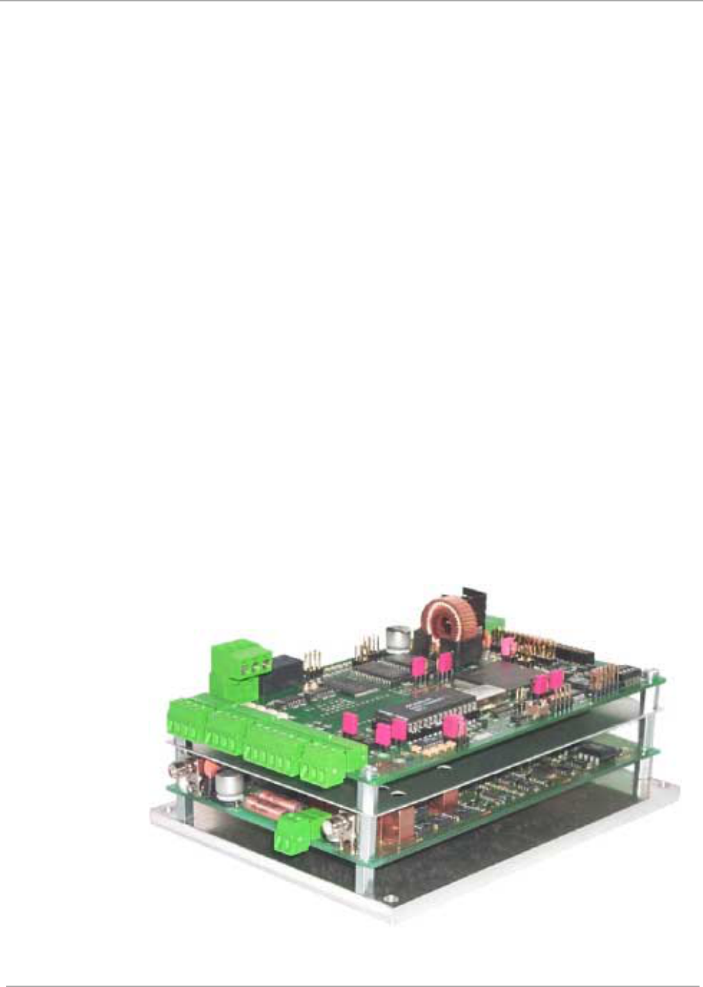
1.3 Product Description
The S6500 Long Range Reader Module handles all RF and digital functions required
in order to communicate with Tag-it HF, Tag-it HF-I (ISO 15693 compliant) and all
other ISO 15693 compliant transponder from various suppliers.
The Reader Module is mounted onto a rigid, 6 mm thick aluminium base plate. The
module has two digital inputs, two digital outputs, a relay output and an asynchro-
nous interface which can be configured as RS232 or RS485.
The configurability of the interfaces also allows the module to be operated on an
RS485 data bus. The address can be assigned either through software or hardware
(3 DIP switches).
Figure 1: S6500 Long Range Reader Module (RI-STU-650A)

7
May ’01 Chapter 1. Introduction
1.1 General
This document provides information about the S6500 Long Range Reader Module.
It describes the reader and how to install it.
1.2 System Description
The HF Reader System Series 6000 works at a frequency of 13.56 MHz. It comprises
a reader, antenna and transponder (for example: smart label) and is used for wire-
less identification of a variety of objects.
The system works according the “reader talks first” principle which means that the
transponder keeps quiet until the reader sends a request to it. The reader can rapidly
and simultaneously identify numerous transponders in the antenna’s field. It can
write data to and read data from the transponders; either in addressed mode by using
the factory programmed read only number, or in general mode to all of the transpond-
ers in its field. The read/write capability of the transponder allows users to update the
data stored in the transponders memory anywhere along its movements.
1.3 Product Description
The S6500 Long Range Reader Module handles all RF and digital functions required
in order to communicate with Tag-it HF, Tag-it HF-I (ISO 15693 compliant) and all
other ISO 15693 compliant transponder from various suppliers.
The Reader Module is mounted onto a rigid, 6 mm thick aluminium base plate. The
module has two digital inputs, two digital outputs, a relay output and an asynchro-
nous interface which can be configured as RS232 or RS485.
The configurability of the interfaces also allows the module to be operated on an
RS485 data bus. The address can be assigned either through software or hardware
(3 DIP switches).
Figure 1: S6500 Long Range Reader Module (RI-STU-650A)
10
S6500 Long Range Reader Module - Reference Guide May ’01
2.1 General
This chapter provides a description of the S6500 Long Range Reader Module hard-
ware. It also provides the electrical specifications of the inputs and outputs.
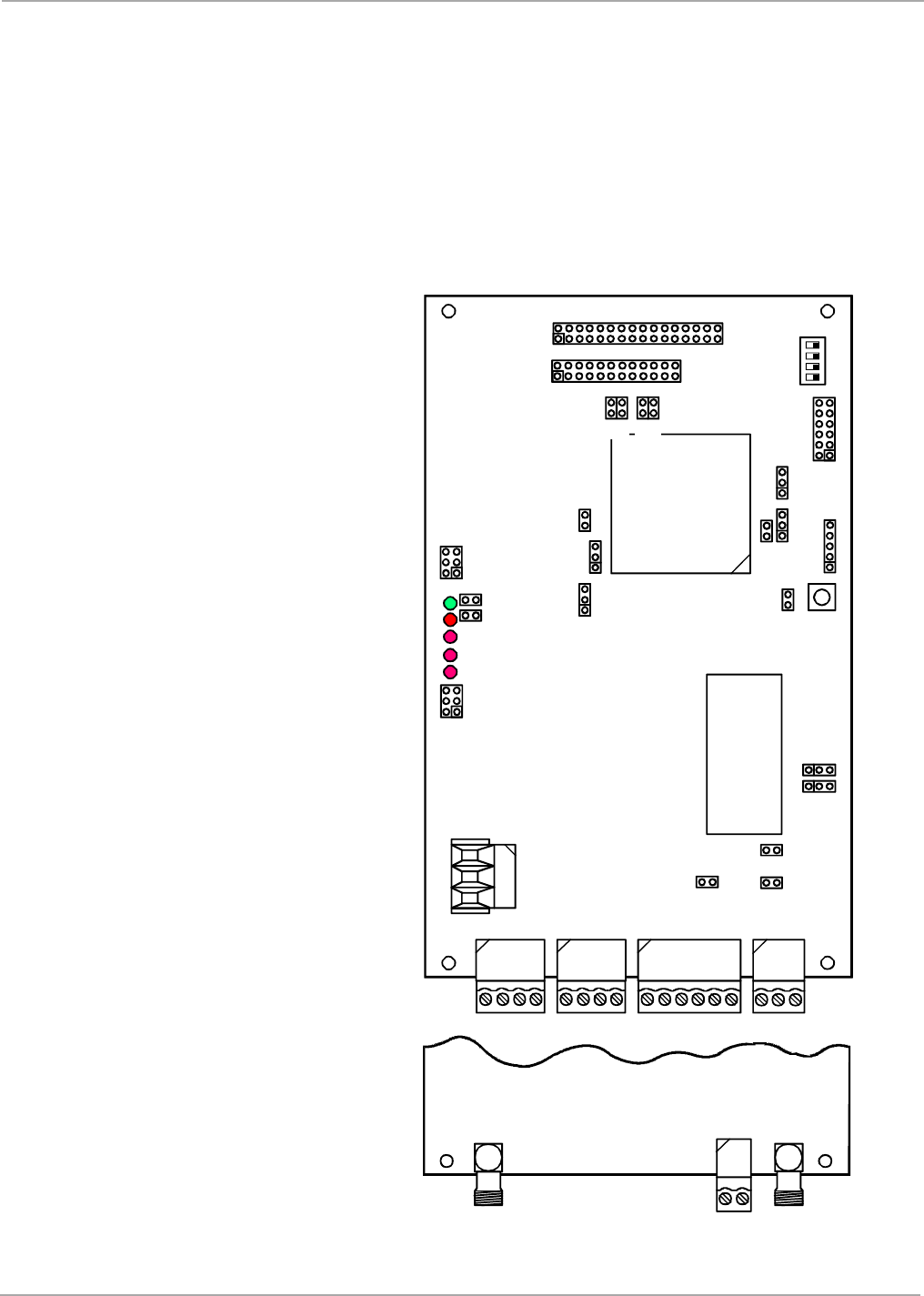
2.2 Mechanical Information
Figure 2 shows the location of the connectors, jumpers and LEDs on the S6500
Reader.
Figure 2: Top View Upper and (part of) Lower pcb
X6 X7 X9 X10
V1
V2
V3
V4
V5
X11
X13
X14
S2
ON
OFF
1 2 3 4
J2
J3
X15
X16
J6
X21
J50 J51
J8
J350
X19
J5
J4
J402
S1
J1
X20
J401
J400
X18
J405
J403
J407
Upper Circuit Board
Lower Circuit Board
X2 X1
X3

11
May ’01 Chapter 2. Reader Hardware
2.3 Connectors
Three connectors are located on the lower pcb and 5 connectors are on the upper
pcb. The connectors are all shown on Figure 2. Table 1 provides an overview of all
the connectors and lists the section that describes them.
2.3.1 Antenna Connectors
There are two antenna connectors on the reader module. They are listed in Table 2.
Table 1: List of Connectors
Identifying Letter Function Section
X1 Rx Only Antenna Connection 2.3.1
X2 Tx/Rx Antenna Connection 2.3.1
X3 Voltage Supply 2.3.2
X6 Isolated Optocoupler Outputs 2.3.4
X7 Isolated Optocoupler Inputs 2.3.3
X9 RS485 Interface 2.3.6
X10 RS232 Interface 2.3.7
X11 Relay Outputs 2.3.5
Table 2: Antenna Connectors
Pin Signal Description
X1 ANT Receive Only Antenna
X2 ANT Transmit/Receive Antenna
Table 3: Antenna - Specifications
Parameter Minimum Maximum
Antenna Q-factor 10 30
Antenna Impedance 50 Ω ± (3 Ω ∠ 3º)
Tightening Torque - 0.45 Nm

12
S6500 Long Range Reader Module - Reference Guide May ’01
2.3.2 Supply Connector (X3)
The supply voltage is connected to connector X3 on the lower circuit board.
2.3.3 Isolated Optocoupler Inputs (X7)
The optocoupler inputs on Terminal X7 are galvanically isolated from the reader elec-
tronics and must therefore be powered by a separate external DC supply. For supply
voltages above 10 V, the input current must be limited to a maximum of 20 mA by an
additional external dropping resistor (see section 3.4.3).
Table 4: Supply Connector
Pin Name Description
1 + 24 V Positive supply
2 GND Ground
Table 5: Supply Connector - Specifications
Parameter Minimum Maximum
Logic Supply Voltage VSL 23.75 V 25.2 V
Logic Supply current ISL - 2.5 A
Connecting Cable Length - 3 m
Ripple (acceptable level) - 20 mV
Table 6: Optocoupler Inputs Connector
Pin Name Description
1 IN1+ + Input 1
2 IN1- - Input 1
3 IN2+ + Input 2
4 IN2- - Input 2
Table 7: Optocoupler Inputs Connector - Specifications
Parameter Minimum Maximum
External Supply Voltage 5 VDC 24 VDC
External Supply Current - 20 mA

14
S6500 Long Range Reader Module - Reference Guide May ’01
2.3.6 RS485 Interface (X9)
Depending on the configuration, the reader module will communicate either via the
RS232 or RS485 interface (see Section 3.5).
The RS485 interface is connected to X9.
The transmission parameters can be software configured.
All interface parameters are according to RS485 specifications and are not given in
detail in this manual.
2.3.7 RS232 Interface (X10)
Depending on the configuration, the reader module will communicate either via the
RS232 or RS485 interface (see Section 3.5).
The RS232 interface is connected to X10.
The transmission parameters can be software configured.
All interface parameters are according to RS232 specifications and are not given in
detail in this manual.
Table 12: RS485 Interface Connector
Pin Name Description Direction
1 Rx+/Tx+ RS485 Non-inverted data Input/Output
2 Rx+/Tx+ RS485 Inverted data Input/Output
3 GND Signal ground -
4- n.c.
5- n.c.
6- n.c.
Table 13: RS232 Interface Connector
Pin Name Description Direction
1 GND Signal ground -
2 RxD Receive data Input
3 TxD Transmit data Output

15
May ’01 Chapter 2. Reader Hardware
2.4 Reader Module LEDs
There are five (one green and four red) LEDs on the reader. Their location is shown
in Figure 2 and their function is described in Table 14.
Table 14: Description of LEDs
Name Description
LED V1 (green)
“RUN-LED”
- If all checks are OK this LED comes on (flashes) when V5
goes out. It indicates that the reader’s internal software is
running properly.
- Flashing rate approximately 1 Hz.
- After a firmware change this LED flashes alternately with V5
until a second reset is performed.
LED V2 (red)
Diagnostic 1: RF communication / EEPROM status
- Short flashing indicates error-free communication with a
transponder on the RF interface.
- Flashes alternating with V1 after a Reset following a software
update.
- Flashes alternating with V1 in case a data error while reading
the parameters occurred following a Reset.
LED V3 (red)
Diagnostic 2: Host communication
- Short flashing indicates a protocol is being sent to the host on
the RS232/RS485 interface.
LED V4 (red) Diagnostic 3: Reserved
LED V5 (red)
Diagnostic 4: Reader initialization / RF error
- Comes on during Reader initialization after power-up or after a
reset, and goes out if everything is OK.
- Comes on to indicate an error in the RF section of the Reader.
The error type can be read out via software on the RS232/
RS485 interface.
- After a firmware change this LED flashes alternately with V1
until a second reset is performed.
16
S6500 Long Range Reader Module - Reference Guide May ’01
2.5 Switches
There are two switches on the reader. Their location is shown in Figure 2 and their
function is described in Table 15.
Table 15: Description of Switches
Name Description
S1 Reset button
S2
1 - Setting data bus addresses (0 ... 7)
2 - Setting data bus addresses (0 ... 7)
3 - Setting data bus addresses (0 ... 7)
4 - not used
Note:
In order to set the bus address using S2, the reader must be set to
software address “0" (default factory setting).
18
S6500 Long Range Reader Module - Reference Guide May ’01
3.1 Introduction
3.2 General
The S6500 Reader Module has been designed with easy installation in mind. The fol-
lowing information provides you with any details that you will need to know.
3.2.1 Default Configuration
The S6500 Reader is delivered with the default configuration as follows:
- Communication Interface: 38400 Baud,
8 data bits,
1 stop bit, even parity
- Antenna Connection: Only TX/RX Antenna active
- Anticollision procedure: active
- Supported Transponder Types: Tag-it HF,
Tag-it HF-I (and other ISO 15693 compliant
transponders)
However, if your system requires that you use the reader with a different configura-
tion, you can use the S6 Reader Utility program which is available at our internet site
http://www.ti-rfid.com (S/W Tools & Download) to re-configure the reader to your sys-
tem’s requirements.
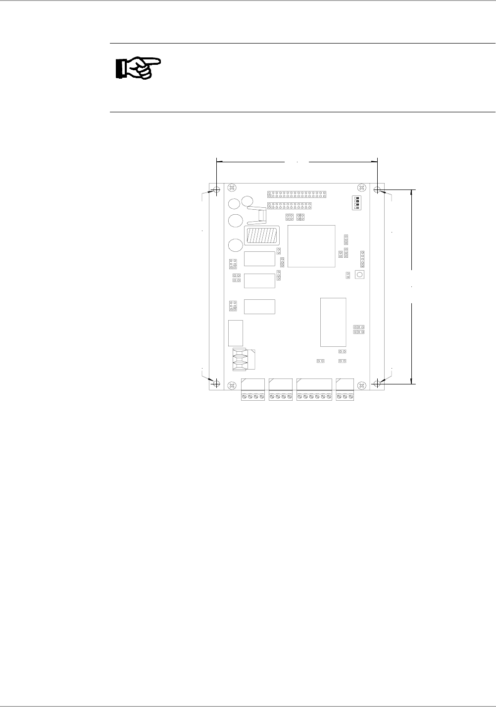
3.3 Mechanical Mounting
Mounting is accomplished using the 4.5 mm diameter holes located in each corner
of the base plate (see Figure 3). If the antenna is properly tuned and there is sufficient
air convection along the mounting plate, the reader can be operated without an ad-
ditional heat sink at up to 4 W of RF power.
If you are going to operate the reader module above 4 W (to fully exploit the reader’s
performance) it must be mounted on an additional heat sink. The heat sink should
have a thermal resistance RThK of maximum 0.8 K/W. When attaching the Reader
Module to the heat sink you should strive for as little heat transfer resistance between
the base plate and the heat sink as possible. We recommend that you use a heat
sink compound.
Note:
Always ensure that the reader is switched off when making or break-
ing connections to it.
Note:
If you are only using one transponder Type in the application, the
reaction time of the reader for transponder read/write operations can
be optimized as long as only one transponder driver (not both of
them) is activated.
19
May ’01 Chapter 3. Installation
Figure 3: Reader Mounting Holes
The tolerances for the position of the mounting holes is ± 0.5 mm.
Note:
Detuning of the antenna can result in additional heat being generated
in the reader. If this happens the reader regulates its output power
down until the final stage is once again within its upper temperature
limit.
150,00 mm
160,00 mm
100 mm
110 mm
120 mm
ø 4,5 mmø 4,5 mm
ø 4,5 mm ø 4,5 mm
20
S6500 Long Range Reader Module - Reference Guide May ’01
3.4 Connectors
3.4.1 Power Supply Connector
The supply voltage is connected to connector X3 on the lower circuit board.
Figure 4: Supply Voltage Connector X3
3.4.2 Antenna Connectors (X1 & X2)
The transmit/receive antenna must be connected to the reader via the antenna SMA
socket (X2). The maximum tightening torque for the SMA socket is 0.45 Nm.
If you are using a receive only antenna (together with the read write antenna) it must
be connected to the reader via the antenna SMA socket (X1). The maximum tighten-
ing torque for the SMA socket is 0.45 Nm.
CAUTIONS:
1. Reversing the power supply wires may destroy the
device.
2. If you are using a switched power supply you must
ensure that the switching frequency is below 300 kHz.
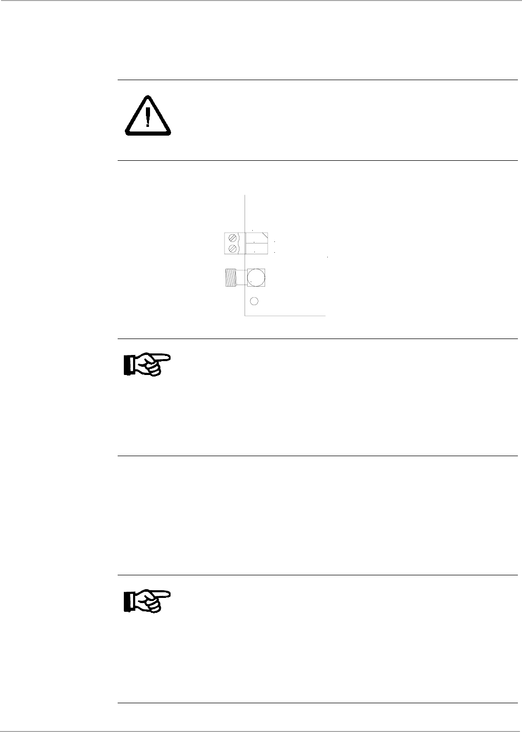
Notes:
1. In order to conform to national requirements for radio devices, the
power supply line must incorporate one of the ∅ 28 mm x 20 mm
ring cores mentioned in section 1.5. The cable must be wound
around the core at least eight times (as shown in Figure 11). The
distance between the ring core and the reader connection must
not be more than 10 cm.
2. In order to avoid interference, the length of the cable between the
power supply and the reader must not exceed 3 m.
Notes:
1. In order to conform to national requirements for radio devices,
each antenna line must incorporate one of the ∅ 28 mm x 20 mm
ring cores mentioned in section 1.5. The cable must be wound
around the core at least four times (as shown in Figure 5). The
distance between the ring core and the reader connection must
not be more than 10 cm.
2. When connecting an antenna, ensure that it does not exceed the
permissible limits as prescribed by the national regulations for
radio frequency devices.
X3
X1
1
2
+24 V DC
GND
!
21
May ’01 Chapter 3. Installation
Figure 5: Antenna Line on a Ring Core
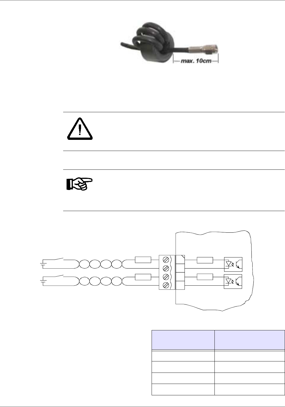
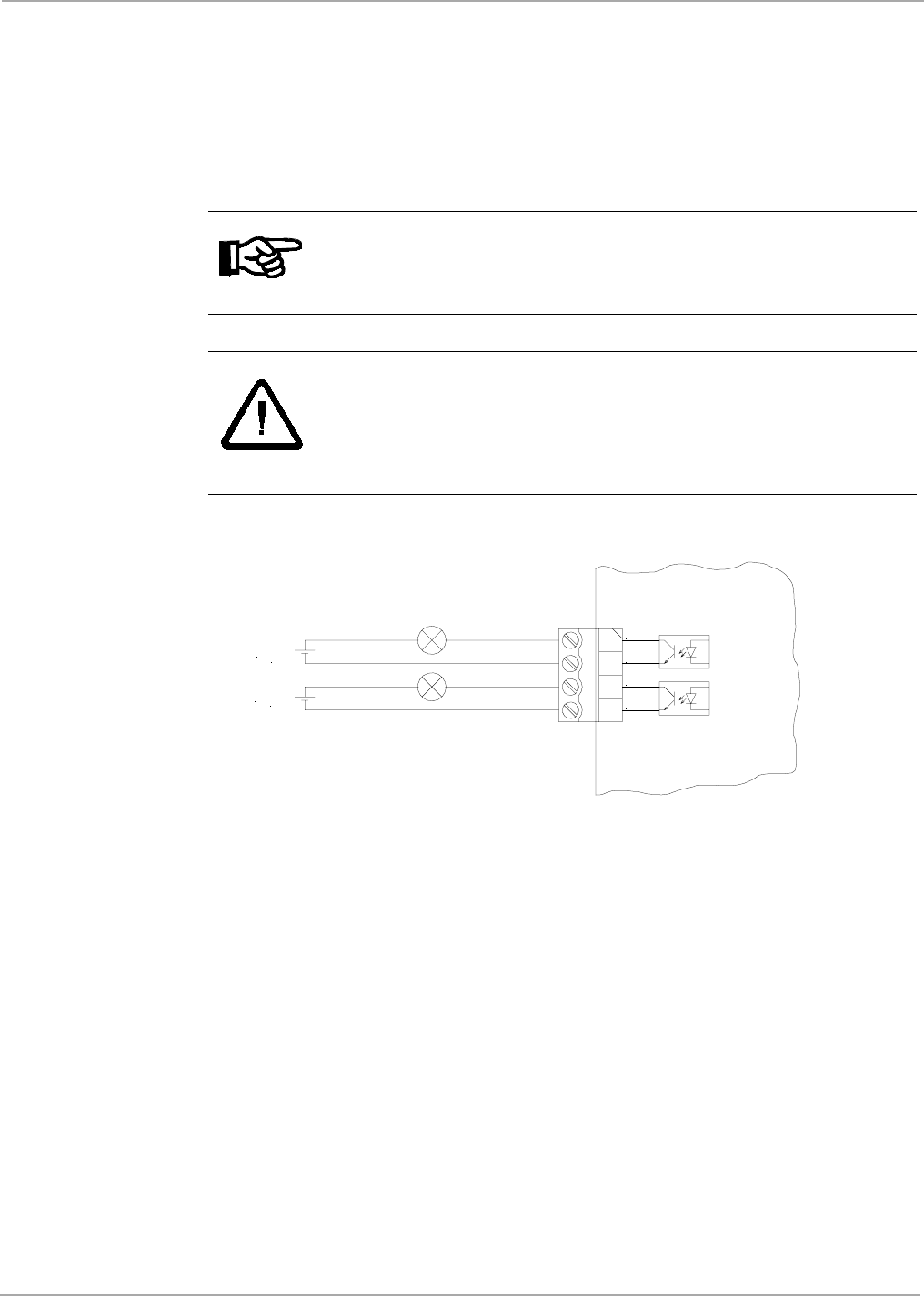
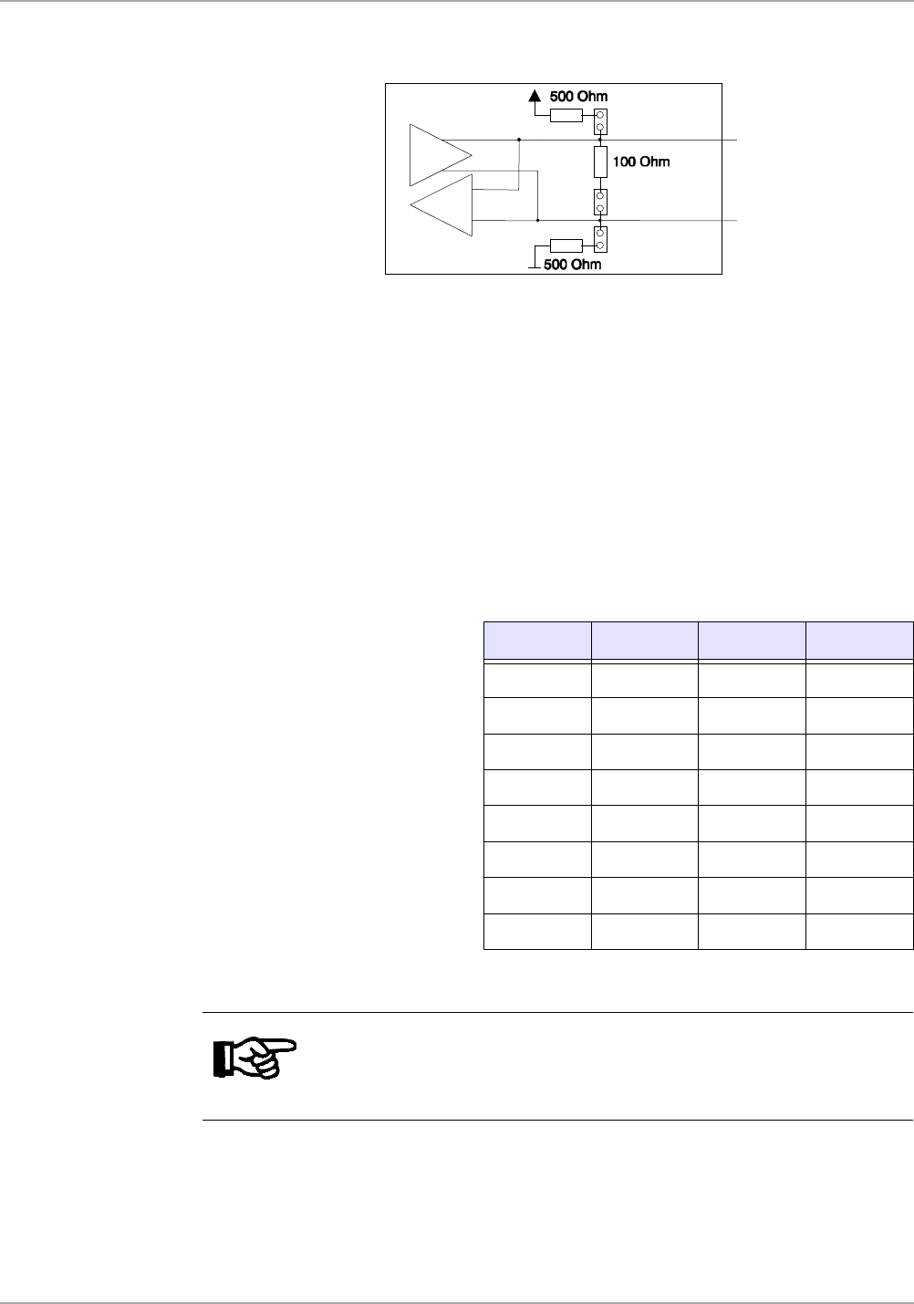
3.4.3 Isolated Optocouplers Input Connector
The input LED's on the optocouplers have an internal input series resistor of 500 Ω.
For supply voltages above 10V the input current must be limited to a maximum of 20
mA by an additional external dropping resistor (see Figure 6 and Table 16).
Figure 6: Optocoupler Input - Internal and External Wiring
CAUTION:
Reversing the polarity or overloading the inputs will
destroy the reader.
Notes:
1. If the connecting cable is longer than 3 m you must use a shielded
cable.
2. You must NOT use the reader’s supply voltage to drive these
inputs as the added noise may reduce the effective reading range.
Table 16: Required External Dropping Resistor
External voltage Vext
Required External
Dropping Resistor Rext
5 V ... 10 V ---
11 V ... 15 V 270 Ω
16 V ... 20 V 560 Ω
21 V ... 24 V 820 Ω
1
2
3
4
Rint
Rint
IN1 +
IN1 -
IN2 +
IN2 -
Rext
Uext
Uext
Rext
X7
22
S6500 Long Range Reader Module - Reference Guide May ’01
3.4.4 Isolated Optocoupler Outputs Connector
The transistor connections, collector and emitter, of the two optocoupler outputs are
galvanically isolated from the reader electronics and brought out on connector X6
without any additional circuitry. The outputs must therefore be powered by external
supplies.
The outputs are designed to switch resistive loads only.
Figure 7: Optocoupler Outputs
Note:
If the connecting cable is longer than 3 m you must use shielded
cable.
CAUTIONS:
Reversing the power supply wires may destroy the device.
X6
1
2
3
4
O1-C
O1-E
O2-C
O2-E
ID ISC.LRM200
U
ext.
U
ext.
X6
23
May ’01 Chapter 3. Installation
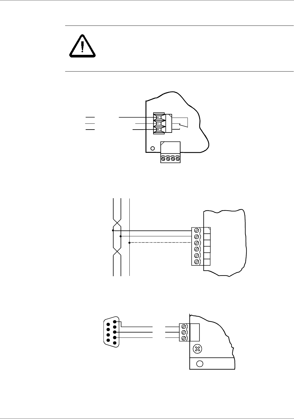
3.4.5 Relay Connector
Figure 8: Relay Connector
3.4.6 RS485 Connection
Figure 9: RS485 Interface
3.4.7 RS232 Connection
Figure 10: RS232 Interface
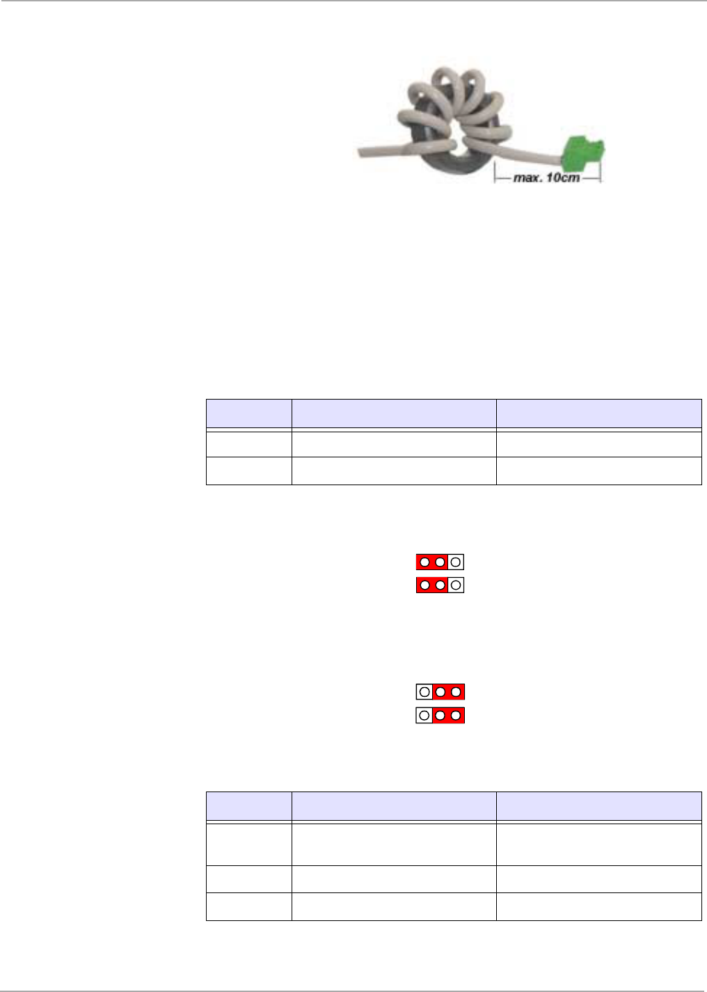
In order to conform to national requirements for radio devices, the interface connec-
tor line must incorporate one of the ring cores mention in section 1.5. The cable must
be wound around the core at least eight times as shown in Figure 11. The distance
between the ring core and the reader connection must not be more than 10 cm.
CAUTIONS:
The two relay change-over contacts are designed to switch
resistive loads only. If you are using an inductive load, the
relay contacts must be protected by means of an external
protection circuit.
X11
1
2
3
common
normally open
normally closed
1
2
3
4
5
6
X9
Tx+/Rx+
Tx-/Rx -
GND
n.c.
n.c.
n.c.
1
2
3
X10
GND
RXD
TXD
5
3
2
9-pin sub-D female
24
S6500 Long Range Reader Module - Reference Guide May ’01
Figure 11: RS232 Interface Line on a Ring Core
3.5 Interface Configuration Jumper Settings
There are five jumpers used on the reader. They are Jumpers J400 - J401 which are
used to configure the asynchronous interface for RS232 or RS485 described in Table
17, and Jumpers J403, J405 and J407 are used to insert the termination resistors
which may be required for the RS485 interface, described in Table 18 and shown in
Figure 14.
Figure 12: Jumper Settings for RS232
Figure 13: Jumper Settings for RS485
Table 17: Jumper Setting - J400 and J401
Jumper RS232 RS485
400 1 - 2 connected 2 - 3 connected
401 1 - 2 connected 2 - 3 connected
Table 18: Jumper Setting - J403, J405 and J407
Jumper In Out
403 Termination resistor between
RS485 - A and RS485 - B
No termination resistor between
RS485 - A and RS485 - B
405 Pull-Up on RS485 - B No Pull-Up on RS485 - B
407 Pull-Down on RS485 - A No Pull-Down on RS485 - A
J401
J400
1
1
J401
J400
1
1
25
May ’01 Chapter 3. Installation
Figure 14: Jumper Settings for RS485 Line Termination
3.6 Setting Bus Addresses
If you are going to use the reader connected to a bus you will have to give each read-
er an individual address. You can do that either by setting switch S2 on the reader or
by software from the controlling computer.
3.6.1 Using S2 to Set the Address
You can use switch S2 to set the reader address between “0" and “7".
To set the bus address using S2, the Reader must be set to software address “0"
(factory setting).
3.6.2 Setting the Reader’s Bus Address through Software
Addresses “0” to 253” can be set by the host computer software, using the S6 Reader
Utility program.
Address S2-1 S2-2 S2-3
0 OFF OFF OFF
1OFFOFF
ON
2OFF
ON OFF
3OFF
ON ON
4ON OFF OFF
5ON OFF ON
6ON ON OFF
7ON ON ON
Note:
When you are using the reader modules in a multi-drop configuration
you must power the readers up one-by-one, giving each reader its
unique address before progressing to the next reader.
J405
J403
J407
RS485 - B+
RS485 - A-

CHAPTER 4
26
Technical Data
Chapter 4:Technical Data
This chapter provides the technical specifications of the S6500 Reader Module. It
also provides information about packing and storage.
Topic Page
4.1 Specification Summary ...........................................................................27
4.2 Mechanical Information ...........................................................................28

27
May ’01 Chapter 4. Technical Data
4.1 Specification Summary
* If the configured output power is above 4 W, an additional 0.8 K/W heat sink is
necessary
Table 19: Ambient Conditions
Operating Temperature -20°C to +65°C
Storage Temperature -40°C to +85°C
Vibration According to EN60068-2-6, 10 Hz to 200 Hz: 0.15 mm / 2 g
Shock According to EN60068-2-27, acceleration 30 g
Table 20: Electrical Data
Supply Voltage 24 VDC +5%/-1%
Ripple: maximum 20 mV
Power Consumption maximum 60 W
Operating Frequency 13.56 MHz ± 7 kHz
Transmitter Power 0.5 to 10 W*
(set by software in steps of 0.25W)
Transmitter Modulation (10% to 30%) ± 6% and 100% (adjustable by software)
Antenna Connection
- Tx/Rx Antenna
- Rx Only Antenna
1 x SMA socket (50W)
1 x SMA socket (50W)
Optocoupler Outputs 24 V DC / 30 mA (galvanically isolated)
Relay (1 x change-over)
Outputs 24 V DC / 60 W
Optocoupler Inputs maximum 24 V DC/ 20 mA
Interfaces RS232 and RS485 (internally selectable)
Memory EEPROM 1 kByte (for parameters; up to 10,000 write
cycles)
RAM 256 kByte (for data)
Flash 512 kByte (for firmware; update via
communication interface)

28
S6500 Long Range Reader Module - Reference Guide May ’01
4.2 Mechanical Information
• Dimensions (W x L x H) 120 x 160 x 69 mm
•Weight 650 g
Figure 15 shows the dimensions of the S6500 Reader. The tolerances are:
Length and Width: ± 0.5 mm
Height: ± 2.0 mm
Figure 15: Reader Dimensions and Mounting Holes
150,00 mm
160,00 mm
100 mm
110 mm
120 mm
6 mm
43 mm
69 mm
ø 4,5 mmø 4,5 mm
ø 4,5 mm ø 4,5 mm

CHAPTER 5
29
Regulatory, Safety and Warranty Notices
Chapter 5:Regulatory, Safety and Warranty Notices
This chapter provides important information about regulatory constraints and safety
precautions.
Topic Page
5.1 Regulatory Notes .....................................................................................30
5.1.1 FCC Notices (U.S.A.) ...........................................................................30
5.1.2 R&TTE Conformity (Europe) ................................................................30
5.2 Safety Precautions...................................................................................31
5.2.1 Human Safety ......................................................................................31
5.2.2 Application Restrictions........................................................................31
5.2.3 ESD Safety Information........................................................................31
5.3 Warranty and Liability..............................................................................31

30
S6500 Long Range Reader Module - Reference Guide May ’01
5.1 Regulatory Notes
An RFID system comprises an RF transmission device, and is therefore subject to
national and international regulations.
Prior to operating the S6500 Long Range Reader Module together with antenna(s)
and power supply, the required FCC, PTT or relevant government agency approval
must be obtained. Sale, lease or operation in some countries may be subject to prior
approval by the government or other organization.
5.1.1 FCC Notices (U.S.A.)
A typical system configuration containing the S6500 Long Range Reader Module has
been tested and found to comply with the limits for a Class A digital device, pursuant
to Part 15 of the FCC Rules. It is the responsibility of the system integrators to get
their complete system tested and to obtain approvals from the appropriate local au-
thorities before operating or selling this system.
5.1.2 R&TTE Conformity (Europe)
A R&TTE Declaration of Conformity is available for the S6500 Long Range Reader
Module at TI*RFID Sales Offices.
The equipment complies with the essential requirements of the Telecommunication
Terminal Equipment Act (FTEG) and the R&TTE Directive 1999/5/EC when used for
its intended purpose.
Any device or system incorporating the S6500 Long Range Reader Module in any
other than the originally tested configuration needs to be verified against the require-
ments of the Telecommunication Terminal Equipment Act (FTEG) and the R&TTE
Directive 1999/5/EC. A separate Declaration of Conformity must be issued by the
System Integrator or user of such a system prior to marketing and operating it in Eu-
ropean Community.
It is the responsibility of the system integrators to get their complete system tested
and to obtain approvals from the appropriate local authorities before operating or
selling the system.
31
May ’01 Chapter 5. Regulatory, Safety and Warranty Notices
5.2 Safety Precautions
5.2.1 Human Safety
5.2.2 Application Restrictions
5.2.3 ESD Safety Information
The Reader Module is packed in special anti-static envelopes, which protect against
electrostatic charge that could cause damage.
• Handle the Reader Module carefully and keep it in the protective envelope until
you are ready to install it.
• Whenever possible, handle the Reader Module by its edges or frame.
5.3 Warranty and Liability
The “General Conditions of Sale and Delivery” of Texas Instruments Incorporated or
a TI subsidiary apply. Warranty and liability claims for defect products, injuries to per-
sons and property damages are void if they are the result of one or more of the fol-
lowing causes:
• improper use of the Reader Modules
• unauthorized assembly, operation and maintenance of the Reader Modules
• operation of the Reader Modules with defective and/or non-functioning safety
and protective equipment
• failure to observe the instructions during transport, storage, assembly, operation,
maintenance and setting up of the Reader Modules
• unauthorized changes to the Reader Modules
• insufficient monitoring of the Reader Modules' operation or environmental condi-
tions
• improperly conducted repairs
• catastrophes caused by foreign bodies and acts of God.
WARNING:
CUSTOMERS USING THE S6500 READER M
ODULE ARE
RESPONSIBLE FOR OPERATING THEIR SYSTEM UNDER IMPLE-
MENTED POWER LEVELS AND ANTENNA CONFIGURATIONS
AGAINST RELEVANT STANDARDS FOR HUMAN SAFETY IN
ELECTRONIC FIELDS.
CAUTIONS:
When integrating these boards into housings appropriate
means of cooling may be necessary in order to prevent
that the combination of environmental temperature and
heat generated by the reader board will not exceed the
specified operating temperature.

APPENDIX A
32
Terms & Abbreviations
The terms and abbreviations used in this manual can be found in the TIRIS Terms
and Abbreviations Manual - document number 11-03-21-002. This manual can be
found in the document center on our home page:
http://www.ti-rfid.com