Texas Dem Pcm2912A Evm Users Manual User's Guide
Texas-Instruments-Dem-Pcm2912A-Evm-Users-Manual-400270 texas-instruments-dem-pcm2912a-evm-users-manual-400270
DEM-PCM2912A EVM sbau141
DEM-PCM2912A EVM to the manual 1f720b22-bec1-4fa8-9218-f35337b125af
PCM2912A%20EVM%20Users%20Guide
2015-02-04
: Texas Texas-Dem-Pcm2912A-Evm-Users-Manual-390461 texas-dem-pcm2912a-evm-users-manual-390461 texas pdf
Open the PDF directly: View PDF ![]() .
.
Page Count: 43
DEM-PCM2912A EVM
User's Guide
Literature Number: SBAU141
January 2009


Contents
Preface ............................................................................................................................... 7
1 Description ................................................................................................................ 9
1.1 Introduction—PCM2912A ................................................................................................ 10
1.1.1 Key Features ....................................................................................................... 10
1.2 Pin Assignments and Terminal Functions .............................................................................. 11
1.3 Functional Block Diagram ................................................................................................. 13
2 Getting Started ......................................................................................................... 15
2.1 Electrostatic Discharge Warning ......................................................................................... 16
2.2 Block Diagram .............................................................................................................. 16
2.3 Interface and Connections ................................................................................................ 16
3 Set-Up Guide ........................................................................................................... 17
3.1 Basic Operating Set-Up—Windows Vista ............................................................................... 18
3.1.1 Basic Setup Before Evaluation .................................................................................. 18
3.1.2 Volume and Mute Settings ....................................................................................... 19
3.1.3 Sampling Frequency .............................................................................................. 21
3.2 Basic Operating Set-Up—Windows XP ................................................................................. 23
3.2.1 Basic Setup Before Evaluation .................................................................................. 23
3.2.2 Volume Settings ................................................................................................... 24
3.3 Basic Operating Set-Up—Mac OS ....................................................................................... 27
3.3.1 Basic Setup Before Evaluation .................................................................................. 27
3.3.2 Volume Settings ................................................................................................... 29
3.3.3 Sampling Frequency .............................................................................................. 30
4 Evaluation and Measurements ................................................................................... 33
4.1 Measurements for Dynamic Characteristics ............................................................................ 34
4.2 Playback Performance ..................................................................................................... 34
4.3 Recording Performance ................................................................................................... 36
5 Schematic, PCB Layout, and Bill of Materials ............................................................... 37
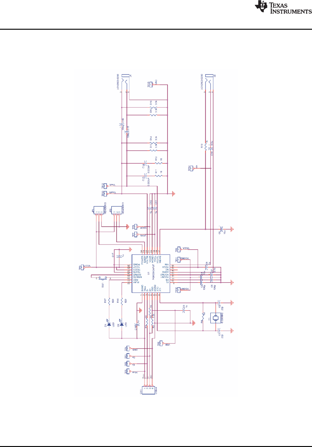
5.1 Schematics .................................................................................................................. 38
5.2 Printed Circuit Board Layout .............................................................................................. 39
5.3 Component List ............................................................................................................. 40
Important Notices ............................................................................................................... 42
SBAU141 – January 2009 Contents 3
Submit Documentation Feedback

www.ti.com
List of Figures
1-1 PCM2912A Pin Assignments ............................................................................................. 11
1-2 DEM-PCM2912A EVM Functional Block Diagram ..................................................................... 13
2-1 DEM-PCM2912A EVM Block Diagram .................................................................................. 16
3-1 Sound—Playback Tab (Windows Vista)................................................................................. 18
3-2 Sound—Recording Tab (Windows Vista) ............................................................................... 18
3-3 Speakers Properties—Levels Tab (Windows Vista) ................................................................... 19
3-4 Microphone Properties—Levels Tab (Windows Vista) ................................................................ 20
3-5 Speakers Properties—Advanced Tab (Windows Vista) ............................................................... 21
3-6 Microphone Properties—Advanced Tab (Windows Vista) ............................................................ 22
3-7 Sound and Audio Devices Properties—Audio Tab (Windows XP) .................................................. 23
3-8 Sound and Audio Devices Properties—Volume Tab (Windows XP) ................................................ 24
3-9 Speaker Window for Volume Setting (Windows XP) .................................................................. 25
3-10 Sound and Audio Devices Properties—Audio Tab (Windows XP) .................................................. 25
3-11 Microphone Volume Windows for Record Volume Setting (Windows XP) ......................................... 26
3-12 Sound—Input Tab (Mac OS) ............................................................................................. 27
3-13 Sound—Output Tab (Mac OS) ........................................................................................... 28
3-14 Audio Midi Setting Window (Mac OS) ................................................................................... 29
3-15 QuickTime Audio Recording Controls ................................................................................... 30
3-16 Audio Midi Setting Window (Mac OS) ................................................................................... 31
4-1 DEM-PCM2912A EVM Configuration for Playback Performance Measurement .................................. 34
4-2 DEM-PCM2912A EVM Configuration for Recording Performance Measurement when Recording Data ...... 36
4-3 DEM-PCM2704EVM Configuration for Recording Performance Measurement with Recorded Data ........... 36
5-1 DEM-PCM2912A EVM Schematic ....................................................................................... 38
5-2 DEM-PCM2912A EVM Board Layout—Silkscreen .................................................................... 39
5-3 DEM-PCM2912A EVM Board Layout—Component Side ............................................................. 39
5-4 DEM-PCM2912A EVM Board Layout—Inner View .................................................................... 39
4List of Figures SBAU141 – January 2009
Submit Documentation Feedback

www.ti.com
List of Tables
1-1 PCM2912A Terminal Functions .......................................................................................... 11
2-1 DEM-PCM2912A EVM Connectors ...................................................................................... 16
4-1 Line Output Playback Performance ...................................................................................... 35
4-2 32- ΩHeadphone Output Playback Performance ...................................................................... 35
4-3 16- ΩHeadphone Output Playback Performance ...................................................................... 35
4-4 Line Input Recording Performance....................................................................................... 36
5-1 Bill of Materials ............................................................................................................. 40
SBAU141 – January 2009 List of Tables 5
Submit Documentation Feedback


PrefaceSBAU141 – January 2009
Read This First
About This Manual
This document provides the information needed to set up and operate the DEM-PCM2912A EVMevaluation module, a test platform for the 16-bit, mono microphone input and stereo headphone output,single-chip PCM2912A stereo audio coder/decoder (codec) with a universal serial bus (USB) interface.For a more detailed description of the PCM2912A product line, refer to the product data sheet availablefrom the Texas Instruments web site at http://www.ti.com . Support documents are listed in the section ofthis guide entitled Related Documentation from Texas Instruments .
How to Use This Manual
Throughout this document, the abbreviation EVM and the term evaluation module are synonymous withthe DEM-PCM2912A EVM.
Chapter 1 gives an overview of the PCM2912A USB interface codec. The EVM block diagram and primaryfeatures are also discussed.
Chapter 2 provides general information regarding EVM handling and unpacking, absolute operatingconditions, and the default switch and jumper configuration.
Chapter 3 is the hardware and software setup guide for the EVM, providing all of the necessaryinformation needed to configure the EVM under various PC operating systems for product evaluation.
Chapter 4 discusses how to configure the DEM-PCM2912A EVM motherboard for performance evaluationusing an audio analyzer.
Chapter 5 includes the EVM electrical schematic, printed circuit board (PCB) layout, and the bill ofmaterials.
Information About Cautions and Warnings
This document contains caution statements.
CAUTION
This is an example of a caution statement. A caution statement describes asituation that could potentially damage your software or equipment.
The information in a caution or a warning is provided for your protection. Please read each caution andwarning carefully.
Macintosh, QuickTime are registered trademarks of Apple Incorporated.SYS-2722 is a registered trademark of Audio Precision, Inc.Windows, Windows Vista, Windows XP are registered trademarks of Microsoft Corporation.All other trademarks are the property of their respective owners.
SBAU141 – January 2009 Read This First 7
Submit Documentation Feedback

Related Documentation From Texas Instruments
www.ti.com
Related Documentation From Texas Instruments
The following documents provide information regarding Texas Instruments integrated circuits used in theassembly of the DEM-PCM2912A EVM. These documents are available from the TI web site . The lastcharacter of the literature number corresponds to the document revision that is current at the time of thewriting of this User’s Guide. Newer revisions may be available from the TI web site at http://www.ti.com/ orcall the Texas Instruments Literature Response Center at (800) 477–8924 or the Product InformationCenter at (972) 644–5580. When ordering, identify the document(s) by both title and literature number.
Data Sheet Literature Number
PCM2912A Product data sheet SLES230
If You Need Assistance
If you have questions regarding either the use of this evaluation module or the information contained in theaccompanying documentation, please contact the Texas Instruments Product Information Center at (972)644–5580 or visit the TI web site at www.ti.com .
FCC Warning
This equipment is intended for use in a laboratory test environment only. It generates, uses, and canradiate radio frequency energy and has not been tested for compliance with the limits of computingdevices pursuant to subpart J of part 15 of FCC rules, which are designed to provide reasonableprotection against radio frequency interference. Operation of this equipment in other environments maycause interference with radio communications, in which case the user at his own expense is required totake whatever measures may be required to correct this interference.
Trademarks
All trademarks are the property of their respective owners.
8Read This First SBAU141 – January 2009
Submit Documentation Feedback

Chapter 1SBAU141 – January 2009
Description
The DEM-PCM2912A EVM is a complete evaluation platform for the 16-bit, mono microphone input andstereo headphone output PCM2912A bus-powered audio codec with a USB interface. All necessaryconnectors and circuitry are provided for interfacing to audio test systems and commercial audioequipment.
A USB connector is mounted on the DEM-PCM2912A EVM. Stereo audio output and mono audio inputare available on two stereo mini-jacks.
Topic .................................................................................................. Page
1.1 Introduction—PCM2912A .......................................................... 10
1.2 Pin Assignments and Terminal Functions .................................... 11
1.3 Functional Block Diagram .......................................................... 13
SBAU141 – January 2009 Description 9
Submit Documentation Feedback

1.1 Introduction—PCM2912A
1.1.1 Key Features
Introduction—PCM2912A
www.ti.com
The PCM2912A is an audio codec with a USB interface for a USB headset, USB headphones, and a USBaudio interface box that integrates mono input, stereo headphone output, an analog loopback line, aprogrammable gain amplifier (PGA), and microphone bias.
It is available in a 32-pin TQFP package.
The DEM-PCM2912A EVM also carries the Microsoft Windows
®
Logo License certification from theMicrosoft Windows Hardware Quality Labs (WHQL). The DEM-PCM2912A has successfully passed theMicrosoft WLP test (DTM Audio) for Windows Vista
®
x86/x64 platforms.
Major features of the PCM2912A include:
•Analog Front End:
– Microphone amplifier (+20 dB gain)
– Mono input
•Analog Back End:
– Stereo/Mono headphone amplifier or line output with volume
•Analog Performance:
– Dynamic range: 90 dB (DAC)
– Dynamic range: 90 dB (ADC)
– 25-mW headphone output at R
L
= 16 Ω
•Power-Supply Voltage
– Single power supply of 5.0 V (V
BUS
)
•Low Power Dissipation:
– 425 mW at analog-to-digital converter (ADC) and digital-to-analog converter (DAC) operation, 44.1kHz
– 0.8 mW in Suspend mode
•Sampling Frequency: 8 kHz, 11.025 kHz, 16 kHz, 22.05 kHz, 32 kHz, 44.1 kHz, 48 kHz for ADC andDAC
•Programmable Function:
– –76-dB to 0-dB gain for analog outputs
– –12-dB to +30-dB gain for analog inputs
– –76-dB to 0-dB gain for sidetone
– 0-dB/20-dB gain for microphone amplifier
– High-pass filter: 0.078 ×f
S
cutoff frequency
•Package: 32-pin TQFP
•Operating Temperature Range: –25 °C to +85 °C
Description 10 SBAU141 – January 2009
Submit Documentation Feedback
1.2 Pin Assignments and Terminal Functions
PCM2912APJT
(32-pinTQFP)
1
24
2
23
3
22
4
21
5
20
6
19
7
18
8
17
9
32
10
31
11
30
12
29
13
28
14
27
15
26
16
25
PGND VIN
VCCP VCCA
TEST1 NC
TEST0 AGND
SSPND VCOM2
MMUTE VCOM1
REC FR
PLAY FL
BGND
VBUS
D-
D+
VDD
DGND
XTO
XTI
POWER
MAMP
V R
OUT
VCCR
HGND
VCCL
V L
OUT
MBIAS
PCM2912APJT
(TopView)
www.ti.com
Pin Assignments and Terminal Functions
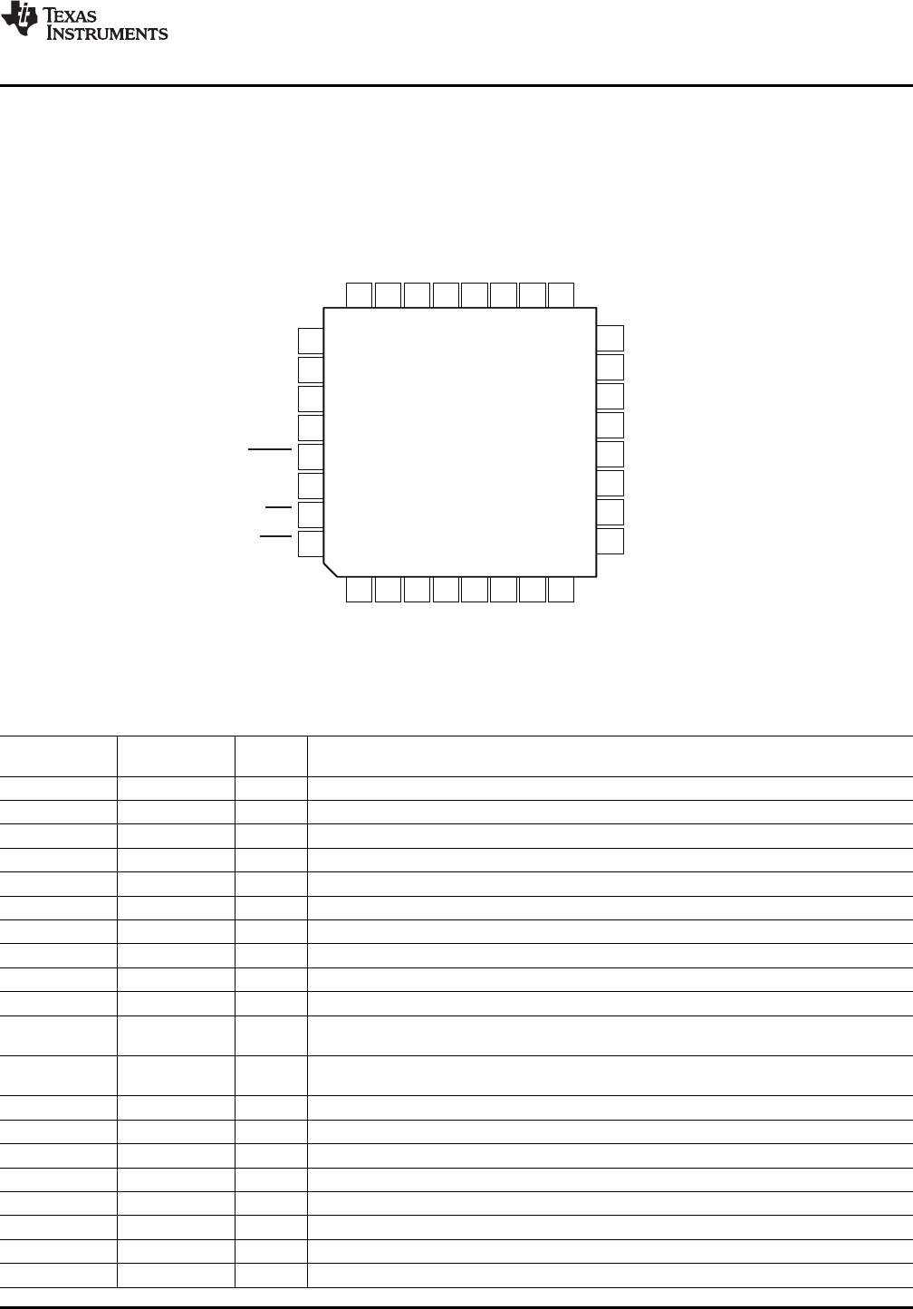
Figure 1-1 shows the pin assignments for the PCM2912A. Table 1-1 lists the terminal functions.
Figure 1-1. PCM2912A Pin Assignments
Table 1-1. PCM2912A Terminal Functions
TQFP-36Name Terminal I/O Description
BGND 1 – Reference for internal regulator
V
BUS
2 – Connect to USB power (V
BUS
)
D– 3 I/O USB differential input/output minus
D+ 4 I/O USB differential input/output plus
V
DD
5 – Digital power supply
DGND 6 Digital ground
XTO 7 O Crystal oscillator output
XTI 8 I Crystal oscillator input
FL 9 – External filter pin of left channel (optional)
FR 10 – External filter pin of right channel (optional)
V
COM1
11 – Common voltage for ADC, DAC and analog front-end (V
CCA
/2). Decoupling capacitor shouldbe connected to AGND.
V
COM2
12 – Common voltage for headphone (V
CCA
/2). Decoupling capacitor should be connected toAGND.
AGND 13 – Analog ground
NC 14 – Not connected
V
CCA
15 – Analog power supply
V
IN
16 I ADC microphone input
MBIAS 17 O Microphone bias output (0.75 V
CCA
)
V
OUT
L 18 O Headphone output for L-channel
V
CCL
19 – Analog power supply for headphone amplifier of L-channel
HGND 20 – Analog ground for headphone amplifier
SBAU141 – January 2009 Description 11
Submit Documentation Feedback
Pin Assignments and Terminal Functions
www.ti.com
Table 1-1. PCM2912A Terminal Functions (continued)
TQFP-36Name Terminal I/O Description
V
CCR
21 -– Analog power supply for headphone amplifier of R-channel
V
OUT
R 22 O Headphone output for R-channel
MAMP 23 I Microphone preamplifier gain control (LOW: Preamplifier off; HIGH: Preamplifier on = +20dB)
POWER 24 I Power consumption declaration select pin (LOW: 100 mA; HIGH: 500 mA)
PGND 25 – Analog ground for microphone bias, microphone amplifier, and PGA
V
CCP
26 – Analog power supply for PLL
TEST1 27 I Test pin. Must be set to high.
TEST0 28 I Test pin. Must be set to low.
SSPND 29 O Suspend flag (LOW: Suspend; HIGH: Operational state)
MMUTE 30 I Microphone mute control, active high (LOW: Mute off; HIGH: Mute on)
REC 31 O Status output for record (LOW: Record; FLASH: Mute on record; HIGH: Stop)
PLAY 32 O Status output for playback (LOW: Playback; FLASH: Mute on playback; HIGH: Stop)
12 Description SBAU141 – January 2009
Submit Documentation Feedback
1.3 Functional Block Diagram
S
S
XTI XTO
6.000MHz
96MHz
PLL(x16) Tracker
(SpAct )
â
USBprotocol
controller
ISO-out
endpoint
Control
endpoint
ISO-in
endpoint
FIFO
FIFO XCVR
Selector
Selector
Analog
PLL
Analog
PLL
USBSIE
VREF
5Vto3.3V
Voltage
Regulator
Power
Manager
ADC
DAC
MIC
Bias
MIC
Amp
BGND V /V /V /V /V
CCA CCP CCL CCR DD AGND/HGND/PGND/DGND
SSPND
VBUS
D+
D-
POWER
MAMP
MMUTE
PLAY
REC
TEST0
TEST1
MBIAS
VIN
VCOM2
VCOM1
V L
OUT
V R
OUT
FL
FR
PGA+30dBto
12dB
in1-dBsteps
-
ATT0dBto 76dB
in1-dBstepswithMute
-
ATT0dBto 76dB
in1-dBstepswithMute
-
HPAMP15mW(at32 )W
www.ti.com
Functional Block Diagram
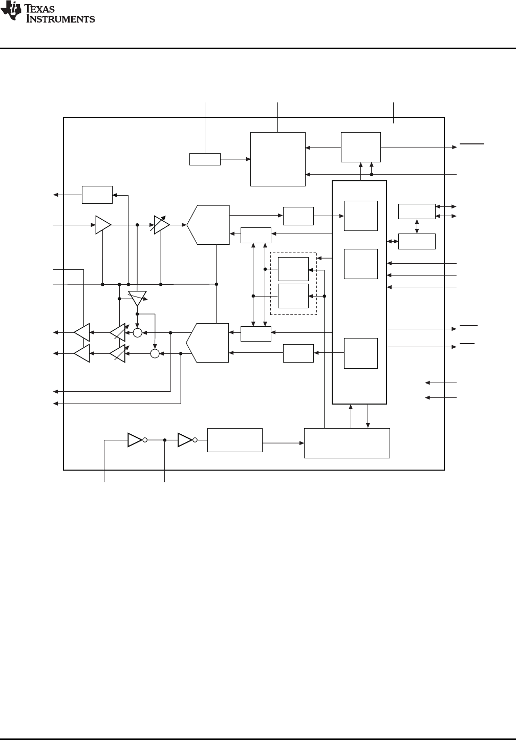
Figure 1-2 illustrates the functional block diagram of the DEM-PCM2912A EVM.
Figure 1-2. DEM-PCM2912A EVM Functional Block Diagram
SBAU141 – January 2009 Description 13
Submit Documentation Feedback


Chapter 2SBAU141 – January 2009
Getting Started
This chapter provides information regarding handling and unpacking the DEM-PCM2912A EVM, as wellas the EVM absolute operating conditions and a description of the factory default switch and jumperconfigurations.
Topic .................................................................................................. Page
2.1 Electrostatic Discharge Warning ................................................. 16
2.2 Block Diagram .......................................................................... 16
2.3 Interface and Connections ......................................................... 16
SBAU141 – January 2009 Getting Started 15
Submit Documentation Feedback
2.1 Electrostatic Discharge Warning
2.2 Block Diagram
PC
USB
Connector
D2 D1
SW1
JP1
J1
JP2
J2
PCM2912A
PCM2912A-EVM
Mic
Headphone
CN1
D+,D-
PLAY
REC
VIN
V L/R
OUT
POWER
MMUTE MAMP
2.3 Interface and Connections
Electrostatic Discharge Warning
www.ti.com
Many of the components on the DEM-PCM2912A EVM are susceptible to damage by electrostaticdischarge (ESD). Customers are advised to observe proper ESD handling precautions when unpackingand handling the EVM, including the use of a grounded wrist strap at an approved ESD workstation.
CAUTION
Failure to observe ESD handling procedures may result in damage to EVMcomponents.
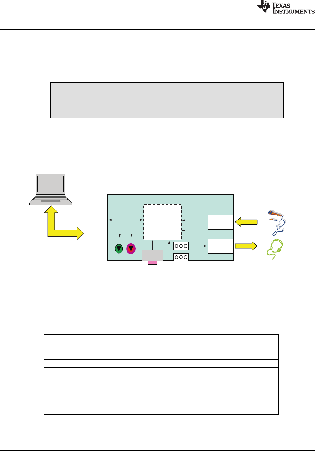
Figure 2-1 illustrates the DEM-PCM2912A EVM block diagram and the default external equipmentconnection configuration.
Figure 2-1. DEM-PCM2912A EVM Block Diagram
Table 2-1 lists the connector references for the DEM-PCM2912A EVM.
Table 2-1. DEM-PCM2912A EVM Connectors
Connectors Part/Description
CN1 USB connector, type A
J1 Mono microphone input
J2 Headphone output terminal
D1 LED (red); record indicator (flash while muting)
D2 LED (green); playback indicator (flash while muting)
SW1 Microphone mute switch
(1)
JP1 Power select (L: 100 mA, H: 500 mA)
JP2 Microphone amplifier gain control(Gain = 0 dB/+20 dB)
(1)
The status of SW1 (microphone mute switch) is not reflected in the Mic Mute status of the Wave Indisplay on a Windows-based PC; the operating system does not support an HID function.
Getting Started16 SBAU141 – January 2009
Submit Documentation Feedback

Chapter 3SBAU141 – January 2009
Set-Up Guide
This chapter discusses how to set up the DEM-PCM2912A EVM on personal computers (PCs) equippedwith any of a variety of major operating systems, including Microsoft Windows Vista
®
, Windows XP
®
, andMacintosh
®
OS X and later.
Topic .................................................................................................. Page
3.1 Basic Operating Set-Up—Windows Vista ..................................... 18
3.2 Basic Operating Set-Up—Windows XP ........................................ 23
3.3 Basic Operating Set-Up—Mac OS ............................................... 27
SBAU141 – January 2009 Set-Up Guide 17
Submit Documentation Feedback
3.1 Basic Operating Set-Up—Windows Vista
3.1.1 Basic Setup Before Evaluation
Basic Operating Set-Up—Windows Vista
www.ti.com
This section reviews how to set up the DEM-PCM2912A EVM for use with a PC equipped with theMicrosoft Vista Basic (or higher) operating system.
When the installation is complete, the EVM software is ready to use.
Follow these steps to set up the DEM-PCM2912A EVM for use with Windows Vista.
Step 1. Connect the USB connector of the DEM-PCM2912A EVM to an available USB connector (orhub) port on the lab PC. The DEM-PCM2912A EVM can be connected directly to the PCwithout an additional USB cable.After the EVM is connected to the PC, the standard Windows Vista driver installsautomatically to the PC. A custom driver for the DEM-PCM2912A is unnecessary.
Step 2. Open the Control Panel from the Start menu ( Start →Control Panel. Open the Sound groupfrom the Control Panel.
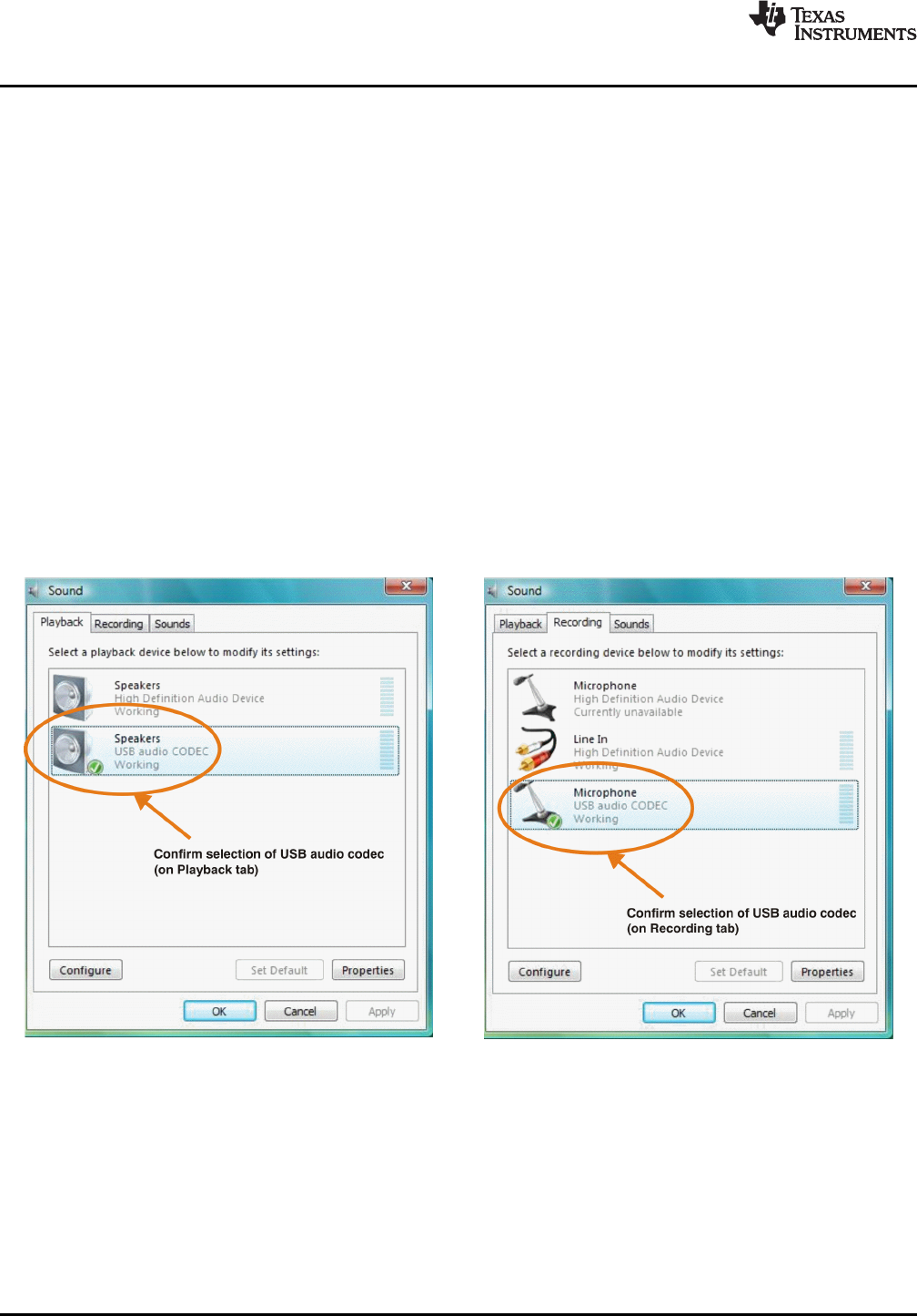
Step 3. Select the playback tab and confirm the USB audio codec appearance as the defaultplayback device, as shown in Figure 3-1 .
Step 4. Select the recording tab and confirm the USB audio codec appearance as the defaultrecording device, as shown in Figure 3-2 .
Figure 3-1. Sound—Playback Tab Figure 3-2. Sound—Recording Tab(Windows Vista) (Windows Vista)
Set-Up Guide18 SBAU141 – January 2009
Submit Documentation Feedback
3.1.2 Volume and Mute Settings
www.ti.com
Basic Operating Set-Up—Windows Vista
Follow these steps to configure the volume settings for headphones, microphone, and the recordingoptions.
To set the headphone volume:
Step 1. Open the Sound options from the Control Panel. ( Start →Control Panel →Sound)
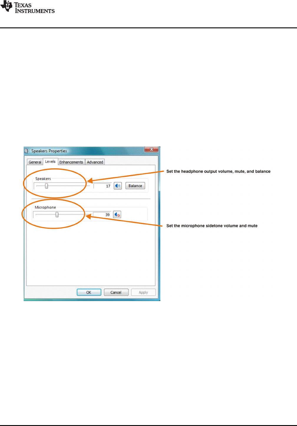
Step 2. Open the speaker properties of the USB audio codec from the Sound options and select theLevels tab, as Figure 3-3 illustrates.
Step 3. Set the output volume, mute, and the balance for headphones from –76 dB to 0 dB.
To set the microphone sidetone:
Step 1. Open the Sound options from the Control Panel. ( Start →Control Panel →Sound)
Step 2. Open the speaker properties of the USB audio codec from the Sound options and select theLevels tab, as Figure 3-3 illustrates.
Step 3. Set the volume and the mute levels for the microphone sidetone from –76 dB to 0 dB.
Figure 3-3. Speakers Properties—Levels Tab (Windows Vista)
SBAU141 – January 2009 Set-Up Guide 19
Submit Documentation Feedback
Basic Operating Set-Up—Windows Vista
www.ti.com
To set the record volume:
Step 1. Open the Sound options from the Control Panel. ( Start →Control Panel →Sound)
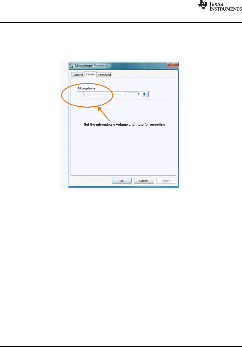
Step 2. Open the microphone properties of the USB audio codec from the Sound options and selectthe Levels tab, as Figure 3-4 illustrates.
Step 3. Set the microphone volume and the recording mute level from –12 dB to +30 dB.
Figure 3-4. Microphone Properties—Levels Tab (Windows Vista)
After this process is complete, the system volume setting for each component is maintained even if EVMis plugged in/out.
Set-Up Guide20 SBAU141 – January 2009
Submit Documentation Feedback
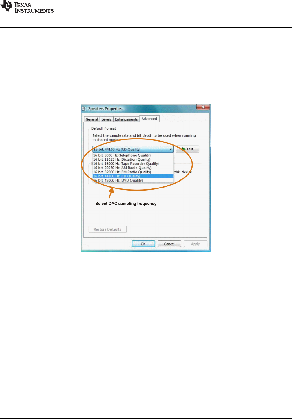
3.1.3 Sampling Frequency
www.ti.com
Basic Operating Set-Up—Windows Vista
Under the Windows Vista operating system, it is necessary to select a specific sampling frequencybecause the sampling frequency cannot be changed on nearly all application software.
To set the DAC sampling frequency:
1. Open the Sound options from the Control Panel. ( Start →Control Panel →Sound)
2. Open the speaker properties of the USB audio codec from the Sound options and select the Advancedtab, as Figure 3-5 illustrates.
3. Select the desired DAC sampling frequency from seven options: 8 kHz, 11.025 kHz,16 kHz, 22.5 kHz,32 kHz, 44.1 kHz, and 48 kHz.
Figure 3-5. Speakers Properties—Advanced Tab (Windows Vista)
SBAU141 – January 2009 Set-Up Guide 21
Submit Documentation Feedback
Basic Operating Set-Up—Windows Vista
www.ti.com
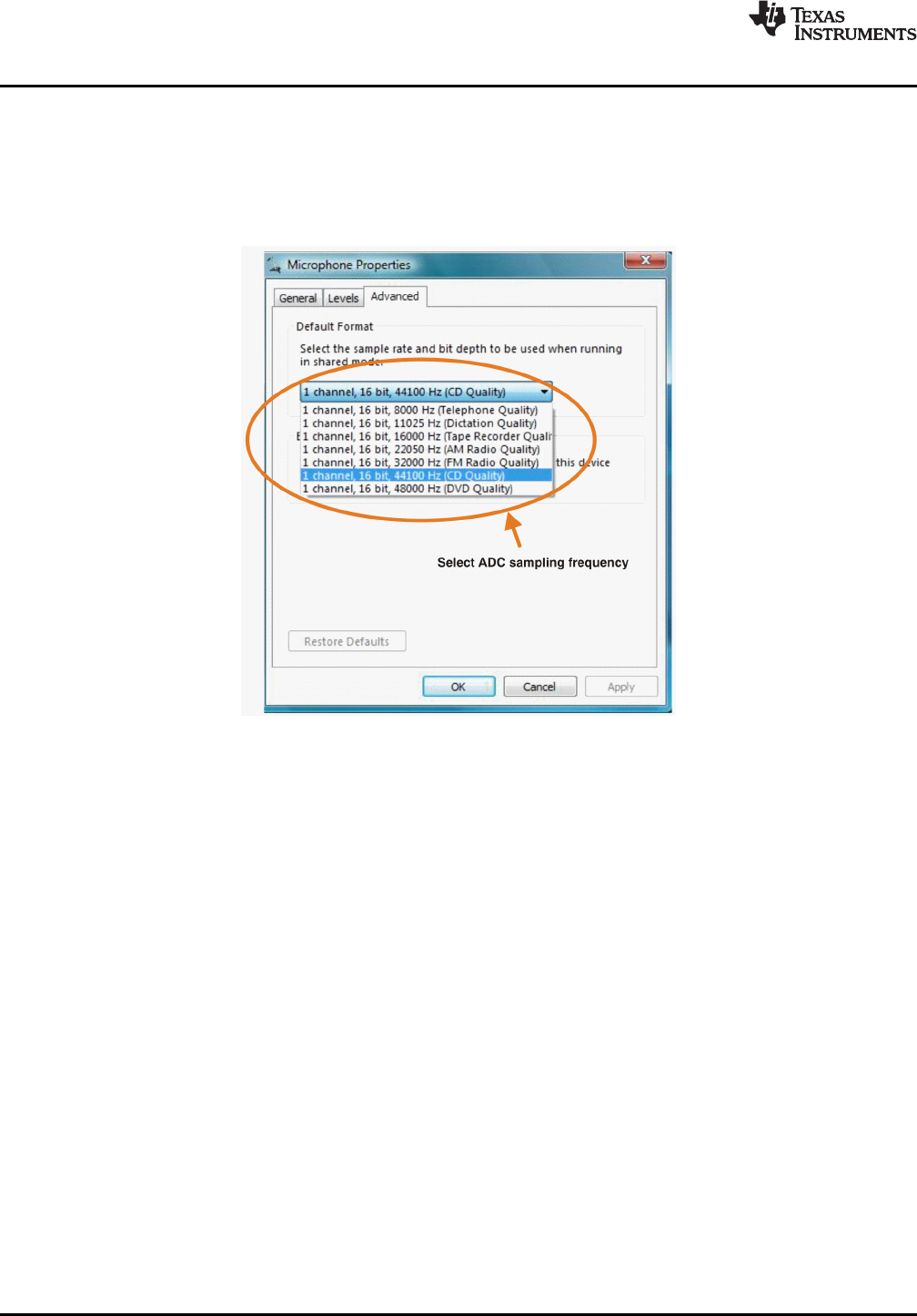
To set the ADC sampling frequency:
1. Open the Sound options from the Control Panel. ( Start →Control Panel →Sound)
2. Open the microphone properties of the USB audio codec from the Sound options and select theAdvanced tab, as Figure 3-6 illustrates.
3. Select the desired ADC sampling frequency from seven options: 8 kHz, 11.025 kHz,16 kHz, 22.5 kHz,32 kHz, 44.1 kHz, and 48 kHz.
Figure 3-6. Microphone Properties—Advanced Tab (Windows Vista)
Set-Up Guide22 SBAU141 – January 2009
Submit Documentation Feedback
3.2 Basic Operating Set-Up—Windows XP
3.2.1 Basic Setup Before Evaluation
www.ti.com
Basic Operating Set-Up—Windows XP
This section reviews how to set up the DEM-PCM2912A EVM for use with a PC equipped with theMicrosoft XP (including Service Pack 2 updates) operating system.
When the installation is complete, the EVM software is ready to use.
Follow these steps to set up the DEM-PCM2912A EVM for use with Windows XP.
Step 1. Connect the USB connector of the DEM-PCM2912A EVM to an available USB connector (orhub) port on the lab PC. The DEM-PCM2912A EVM can be connected directly to the PCwithout an additional USB cable.After the EVM is connected to the PC, the standard Windows XP driver installs automaticallyto the PC. A custom driver for the DEM-PCM2912A is unnecessary.
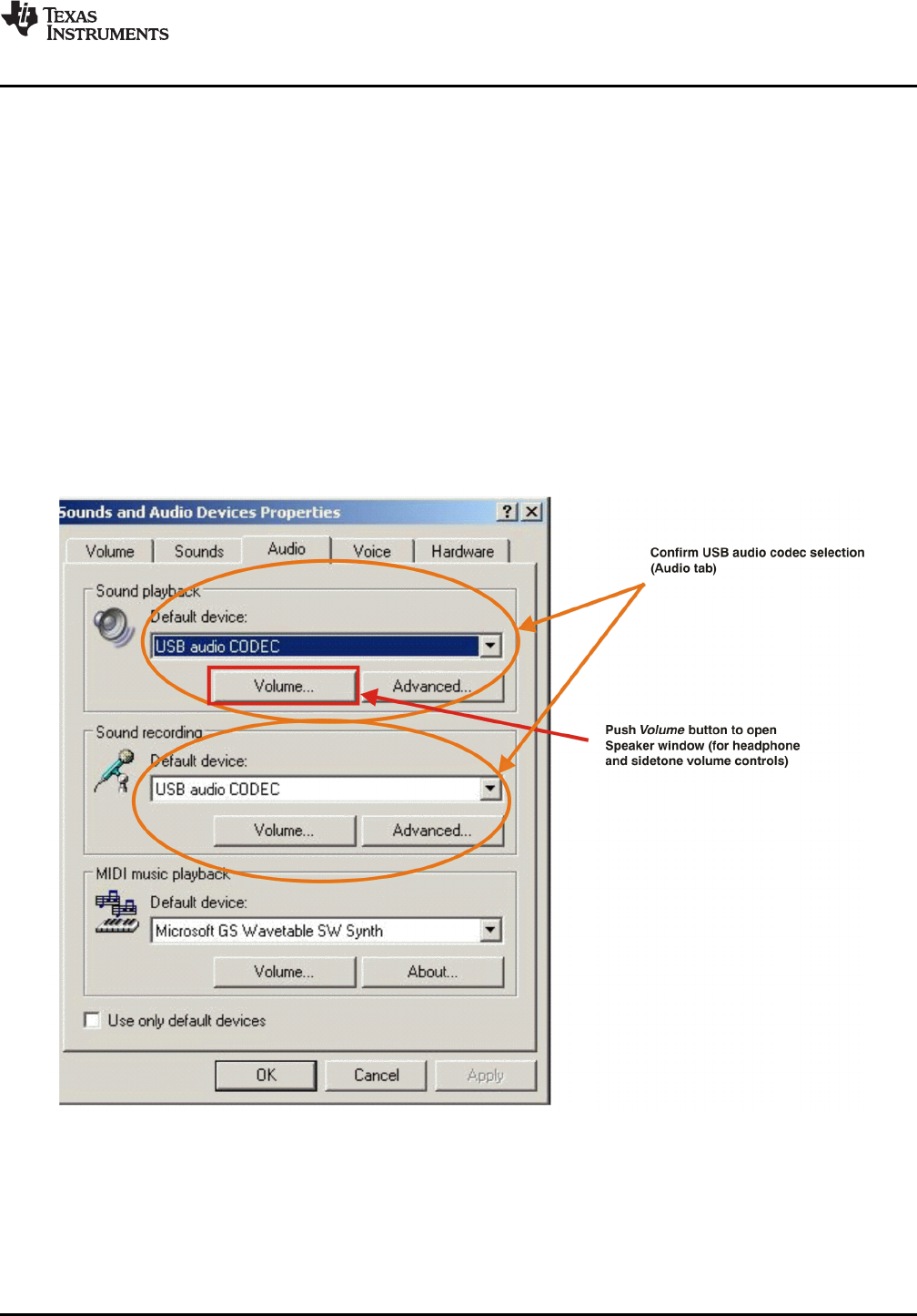
Step 2. Open the Control Panel from the Start menu ( Start →Control Panel. Open the Sound andAudio Devices group from the Control Panel.
Step 3. Select the Audio tab and confirm the USB audio codec appearance as the default playbackand recording device, as shown in Figure 3-7 .
Figure 3-7. Sound and Audio Devices Properties—Audio Tab (Windows XP)
This process confirms the proper recognition of the DEM-PCM2912A EVM by Windows XP.
SBAU141 – January 2009 Set-Up Guide 23
Submit Documentation Feedback
3.2.2 Volume Settings
Basic Operating Set-Up—Windows XP
www.ti.com
Follow these steps to configure the volume settings for headphones, microphone, and the recordingoptions.
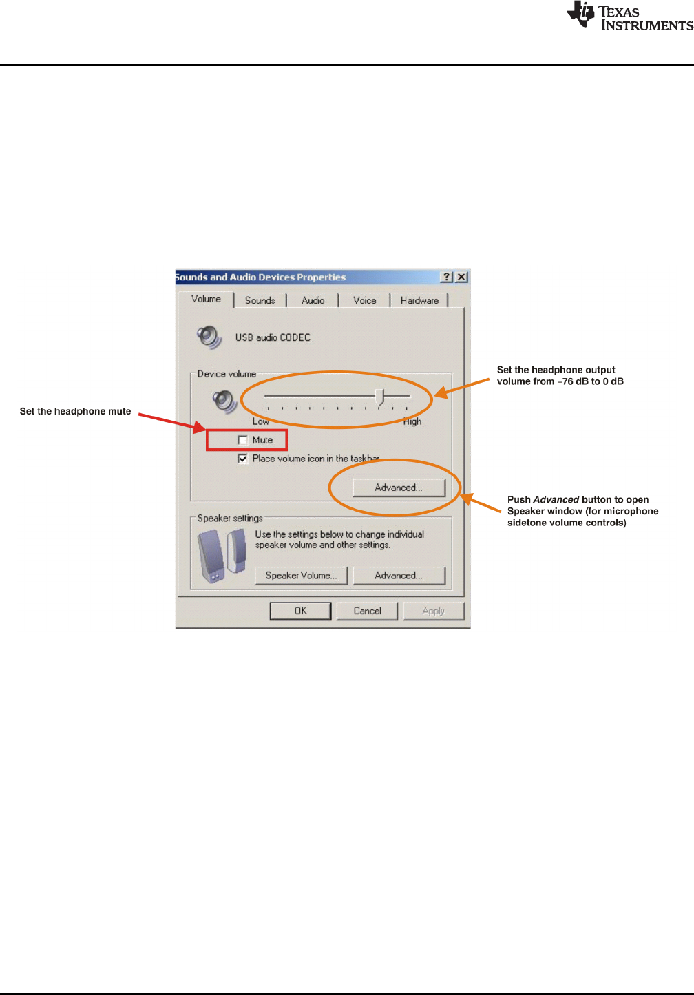
To set the headphone volume:
Step 1. Open the Sound options from the Control Panel. ( Start →Control Panel →Sound)
Step 2. Open the Sound and Audio Devices Properties dialog box and select the Volume tab, asFigure 3-8 illustrates. Alternatively, open the Speakers window from the Volume selection box(on the Audio tab) or the Advanced selection box (on the Volume tab); see Figure 3-7 .
Step 3. Set the output volume and the mute levels for headphones from –76 dB to 0 dB. The initialvolume setting upon installation is approximately –15 dB.
Figure 3-8. Sound and Audio Devices Properties—Volume Tab (Windows XP)
24 Set-Up Guide SBAU141 – January 2009
Submit Documentation Feedback
www.ti.com
Basic Operating Set-Up—Windows XP
To set the microphone sidetone:
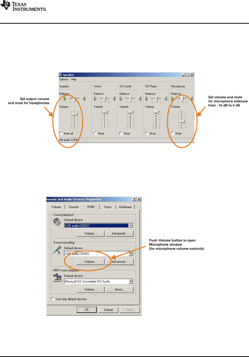
1. Open the Speakers options from the Volume selection box (on the Audio tab) or the Advancedselection box (on the Volume tab); see Figure 3-8 . Alternatively, double-click the speaker icon (ifdisplayed) in the lower right-hand area of the Windows taskbar (at the bottom of the screen); seeFigure 3-7 .
2. Set the volume and the mute levels for the microphone sidetone from –76 dB to 0 dB, as shown inFigure 3-9 . The initial volume setting upon installation is approximately –8 dB.
Figure 3-9. Speaker Window for Volume Setting (Windows XP)
To set the record volume:
1. Open the Sound options from the Control Panel. ( Start →Control Panel →Sound)
2. Open the Sound and Audio Devices Properties dialog box and select the Microphone tab, asFigure 3-10 illustrates.
Figure 3-10. Sound and Audio Devices Properties—Audio Tab (Windows XP)
SBAU141 – January 2009 Set-Up Guide 25
Submit Documentation Feedback
Basic Operating Set-Up—Windows XP
www.ti.com
space
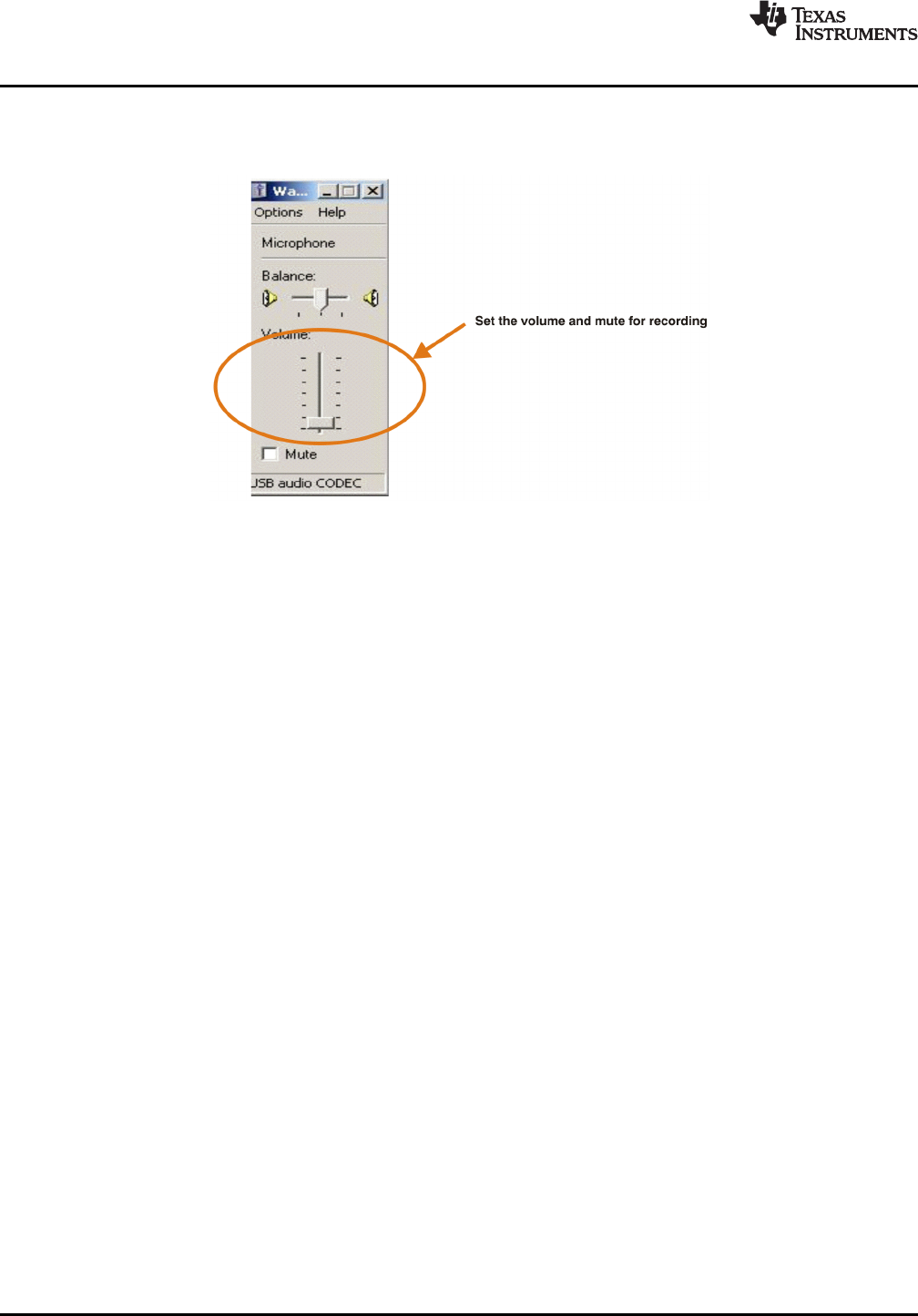
3. Set the microphone volume and the recording mute level from –12 dB to +30 dB, as shown inFigure 3-11 . The initial volume setting upon installation is approximately +8 dB.
Figure 3-11. Microphone Volume Windows for Record Volume Setting (Windows XP)
After this process is complete, the system volume setting for each component is maintained even if EVMis plugged in/out.
Set-Up Guide26 SBAU141 – January 2009
Submit Documentation Feedback
3.3 Basic Operating Set-Up—Mac OS
3.3.1 Basic Setup Before Evaluation
www.ti.com
Basic Operating Set-Up—Mac OS
This section reviews how to set up the DEM-PCM2912A EVM for use with a Macintosh computerequipped with the Mac OS X (or later) operating system.
When the installation is complete, the EVM software is ready to use.
Follow these steps to set up the DEM-PCM2912A EVM for use with a Macintosh computer.
Step 1. Connect the USB connector of the DEM-PCM2912A EVM to an available USB connector (orhub) port on the lab computer. The DEM-PCM2912A EVM can be connected directly to thePC without an additional USB cable.After the EVM is connected to the PC, the standard Mac OS driver installs automatically tothe computer system. A custom driver for the DEM-PCM2912A is unnecessary.
Step 2. Open the System Environment Settings from the Start menu. Open the Sound options fromthe System Environment settings.
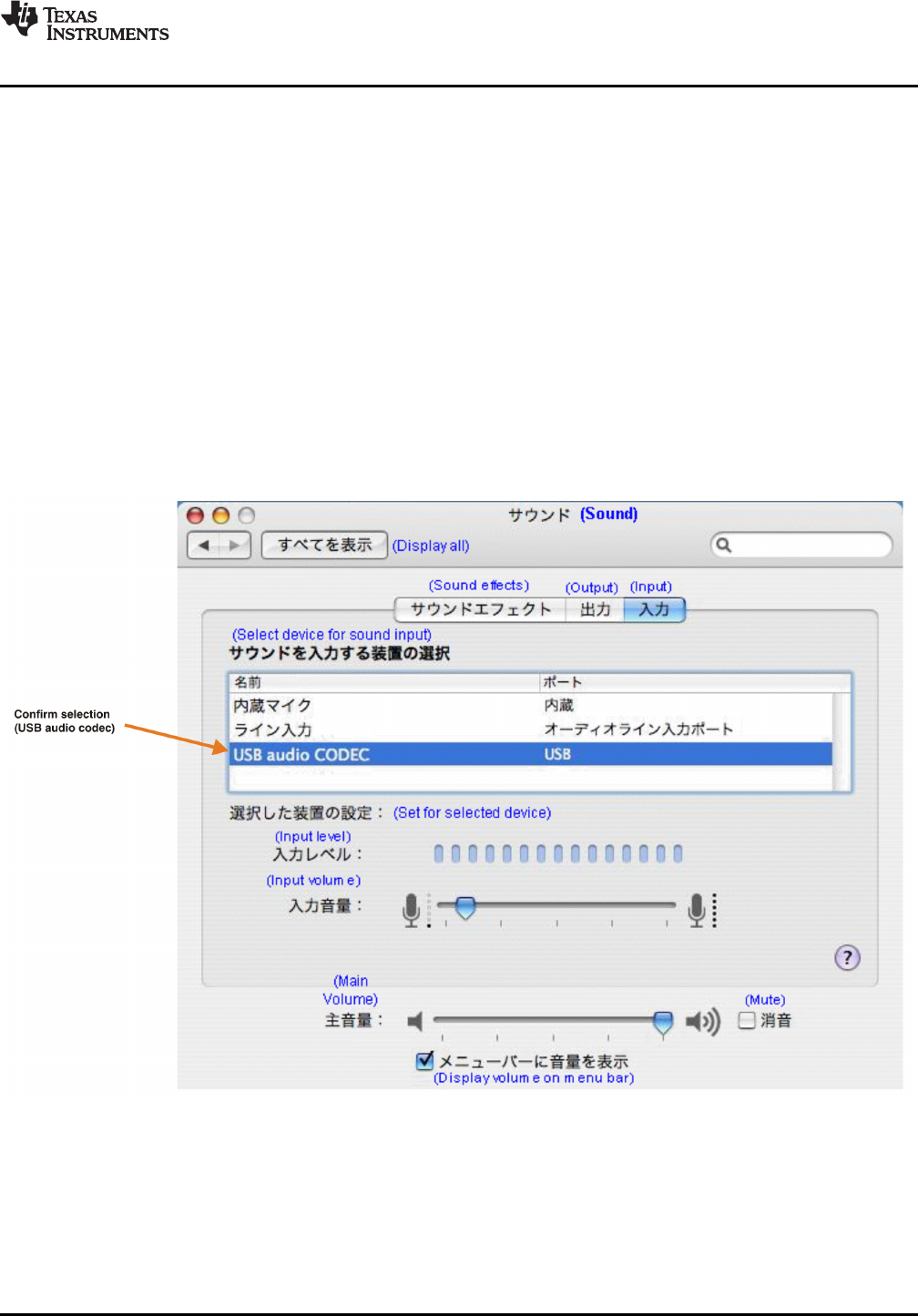
Step 3. Select the Input tab and confirm the USB audio codec appearance as the default recordingdevice, as shown in Figure 3-12 .
Figure 3-12. Sound—Input Tab (Mac OS)
SBAU141 – January 2009 Set-Up Guide 27
Submit Documentation Feedback
Basic Operating Set-Up—Mac OS
www.ti.com
space
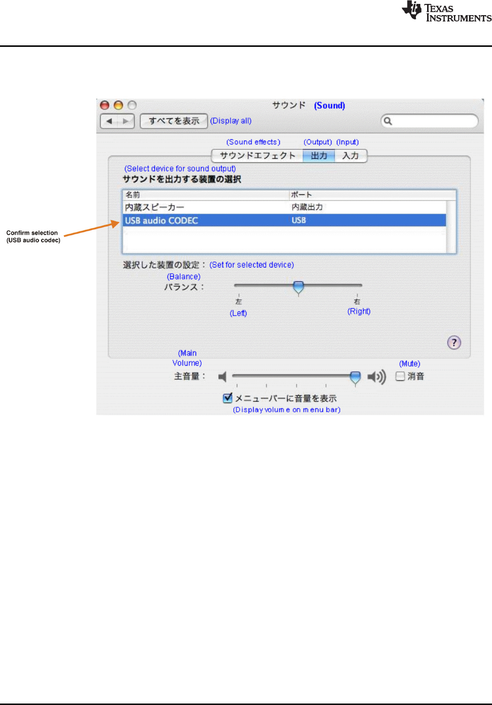
Step 4. Select the Output tab and confirm the USB audio codec appearance as the default playbackdevice, as shown in Figure 3-13 .
Figure 3-13. Sound—Output Tab (Mac OS)
This process confirms the proper recognition of the DEM-PCM2912A EVM by Mac OS X.
Set-Up Guide28 SBAU141 – January 2009
Submit Documentation Feedback
3.3.2 Volume Settings
www.ti.com
Basic Operating Set-Up—Mac OS
Follow these steps to configure the volume settings for headphones, microphone, and the recordingoptions.
To set the headphone volume:
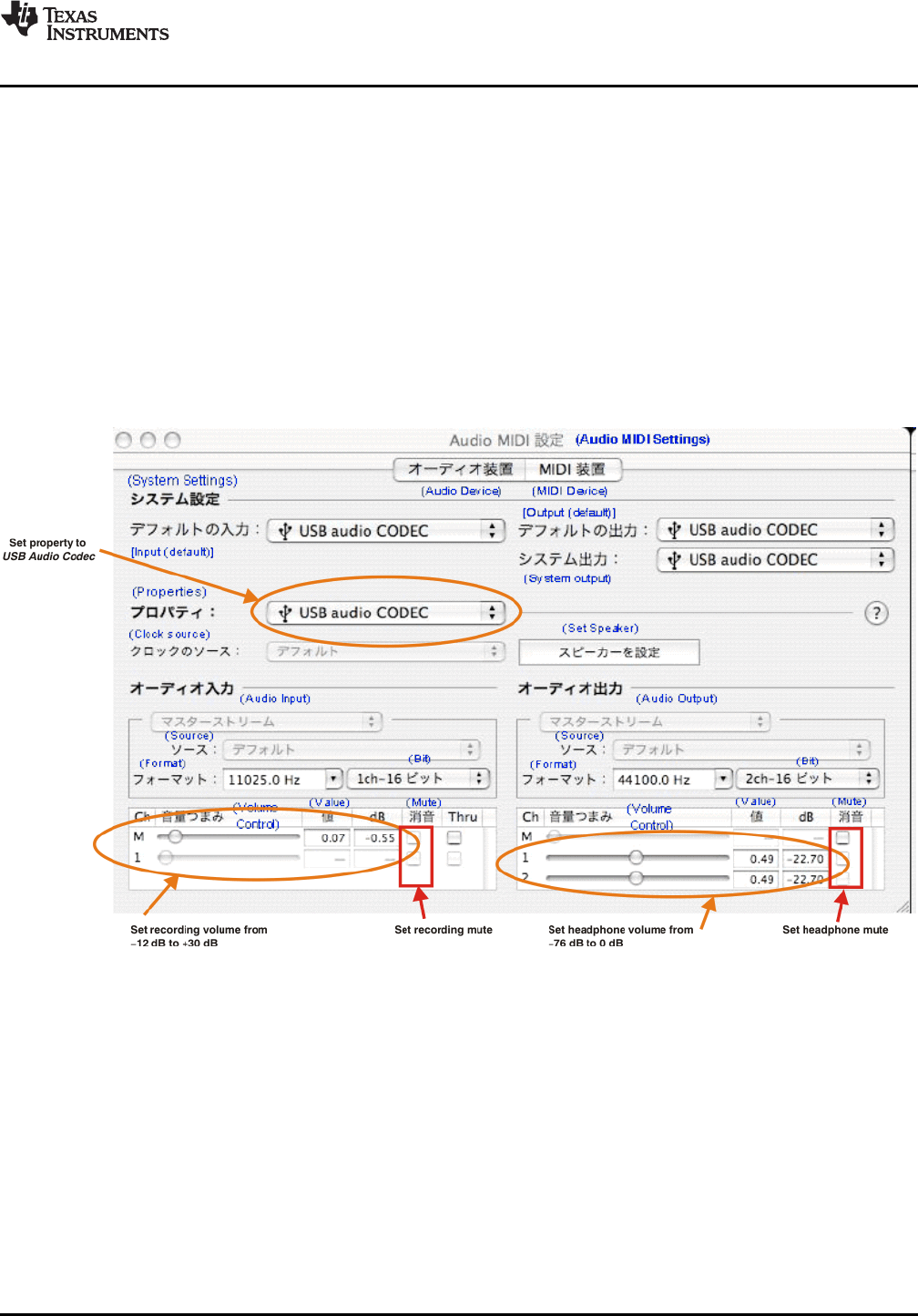
Step 1. Open the Audio MIDI Settings options ( Application →Utility →Set Audio MIDI), as illustrated inFigure 3-14 . Alternatively, open the Output tab of the Sound options, as illustrated inFigure 3-13 .
Step 2. Set the headphone volume and the audio output levels from –76 dB to 0 dB, and set thedesired mute.
To set the record volume:
1. Open the Audio MIDI Settings options ( Application →Utility →Set Audio MIDI), as illustrated inFigure 3-14 . Alternatively, open the Input tab of the Sound options, as illustrated in Figure 3-12 .
2. Set the recording level from –12 dB to +30 dB, and set the desired mute.
Figure 3-14. Audio Midi Setting Window (Mac OS)
SBAU141 – January 2009 Set-Up Guide 29
Submit Documentation Feedback
3.3.3 Sampling Frequency
Basic Operating Set-Up—Mac OS
www.ti.com
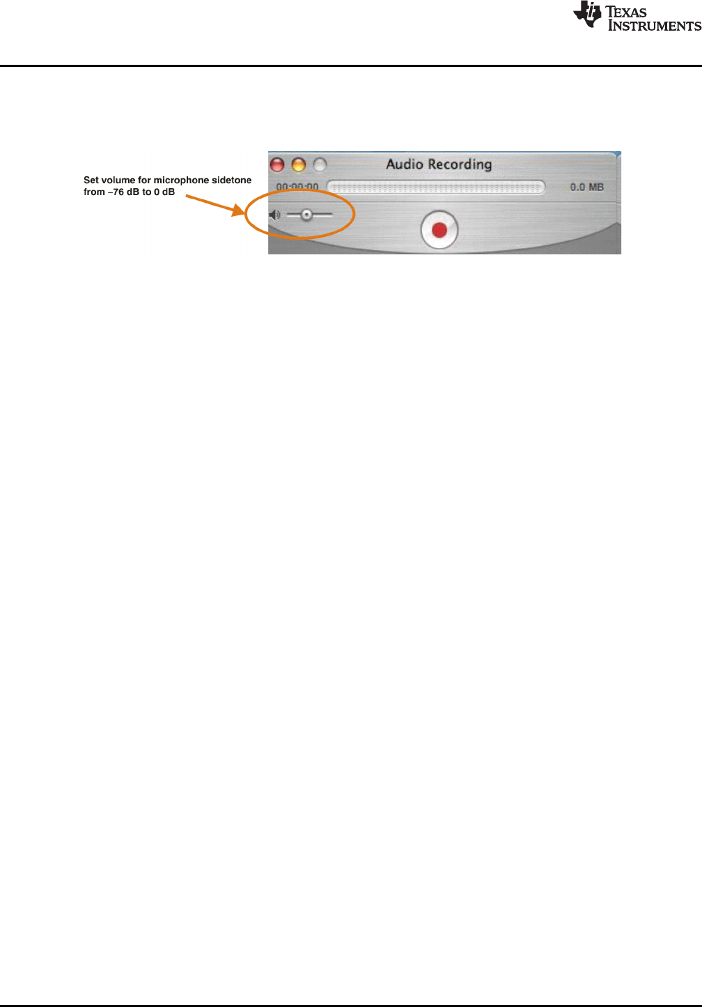
To set the microphone sidetone:
The volume setting of the microphone sidetone is controlled by the individual application software onthe Mac. For example, Audio Recording using QuickTime
®
(as shown in Figure 3-15 ) sets themicrophone volume for sidetone from –76dB to 0dB.
Figure 3-15. QuickTime Audio Recording Controls
After this process is complete, the system volume setting for each component is maintained even if EVMis plugged in/out.
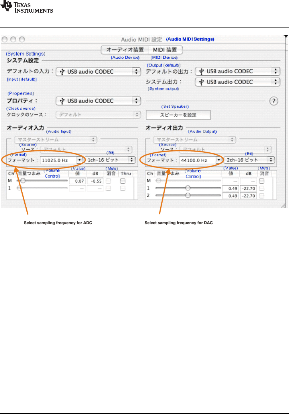
Under the Mac OS X operating system, it is necessary to select a specific sampling frequency becausethe sampling frequency cannot be changed on nearly all application software.
To set the DAC sampling frequency:
1. Open the Audio MIDI Settings options ( Application →Utility →Set Audio MIDI), as illustrated inFigure 3-16 .
2. Select the Audio Input tab in the Set Audio MIDI options group, as Figure 3-16 shows.
3. Select the desired DAC sampling frequency from seven options: 8 kHz, 11.025 kHz,16 kHz, 22.5 kHz,32 kHz, 44.1 kHz, and 48 kHz.
To set the ADC sampling frequency:
1. Open the Audio MIDI Settings options ( Application →Utility →Set Audio MIDI), as illustrated inFigure 3-16 .
2. Select the Audio Output tab in the Set Audio MIDI options group, as shown in Figure 3-16 .
3. Select the desired ADC sampling frequency from seven options: 8 kHz, 11.025 kHz,16 kHz, 22.5 kHz,32 kHz, 44.1 kHz, and 48 kHz.
30 Set-Up Guide SBAU141 – January 2009
Submit Documentation Feedback


Chapter 4SBAU141 – January 2009
Evaluation and Measurements
This chapter discusses how to set up the DEM-PCM2912A EVM for performance evaluation using theAudio Precision SYS-2722
®
audio analyzer. The process of measuring dynamic characteristics is thenpresented, along with example characteristic data.
Topic .................................................................................................. Page
4.1 Measurements for Dynamic Characteristics ................................. 34
4.2 Playback Performance ............................................................... 34
4.3 Recording Performance ............................................................. 36
SBAU141 – January 2009 Evaluation and Measurements 33
Submit Documentation Feedback

4.1 Measurements for Dynamic Characteristics
4.2 Playback Performance
PC Playingtestdataatf =44.1kHzbyapplicationsoftware
(forexample,SoundRecorder,MediaPlayer,etc.)
S
USB
Connector
D2 D1
SW1 JP1
J1
JP2
J2
100mA
0dB
PCM2912A
PCM2912A-EVM
Mic
Headphone
AudioPrecision
SYS-2722
AnalogAnalyzer
Leftch
Rightch
RL
Measurements for Dynamic Characteristics
www.ti.com
Typical dynamic performance graphs for playback and recording devices generally represent threeperformance characteristics (in addition to other specifications): total harmonic distortion and noise(THD+N); signal-to-noise ratio (SNR); and dynamic range (DR). For playback devices, channel separationis also a performance characteristic. These graphs also specify the test environment and measurementconditions required in order to meet typical performance values defined in the product data sheet.
For the DEM-PCM2912A EVM, the evaluation environment specifications are:
•Equipment used: Audio Precision, System Two Cascade Plus
•Power supply: V
BUS
= 5.0 V (Bus power setting)
•Temperature: Room/ambient
The DEM-PCM2912A EVM performance presented in this section was obtained under the followingconditions:
•f
S
= 44.1 kHz
•Output PGA (Speaker output volume): 0 dB
•Sidetone from microphone PGA: –76 dB (mute)
•R
L
= 10 k Ω/ 32 Ω/ 16 Ωare inserted into headphone jack J2 for headphone output
•Jumper setting: set JP1 to 100 mA and JP2 to 0 dB
•Application software for playback: Sound Recorder, Media Player and ITunes for Windows Vista/XP;QuickTime and ITunes for Mac OS X.
•Equipment: AP2 Analog Analyzer (SYS-2722)
Configure the equipment as shown in Figure 4-1 .
Figure 4-1. DEM-PCM2912A EVM Configuration for Playback Performance Measurement
34 Evaluation and Measurements SBAU141 – January 2009
Submit Documentation Feedback

www.ti.com
Playback Performance
Table 4-1. Line Output Playback Performance
Power Supply Performance Filter Setting R
L
V
OUT
L V
OUT
R
5.0 V THD+N (0 dBFS at 400 Hz to 20 kHz 10 k Ω0.0086% 0.0085%1 kHz) Pre-Anlr
SNR (BPZ input) 400 Hz to 20 kHz 10 k Ω92.1 dB 92.1 dBPre-Anlr
+ A-weighting
DR (–60 dBFS 400 Hz to 20 kHz 10 k Ω90.3 dB 90.5 dBinput) Pre-Anlr
+ A-weighting
Channel Separation 400 Hz to 20 kHz 10 k Ω89.3 dB 89.3 dB(BPZ input for target Pre-Anlrchannel)
Table 4-2. 32- ΩHeadphone Output Playback Performance
Power Supply Performance Filter Setting R
L
V
OUT
L V
OUT
R
5.0 V THD+N (0 dBFS at 400 Hz to 20 kHz 32 Ω0.026% 0.025%1 kHz) Pre-Anlr
SNR (BPZ input) 400 Hz to 20 kHz 32 Ω92.1 dB 92.1 dBPre-Anlr
+ A-weighting
DR (–60 dBFS 400 Hz to 20 kHz 32 Ω89.4 dB 89.4 dBinput) Pre-Anlr
+ A-weighting
Table 4-3. 16- ΩHeadphone Output Playback Performance
Power Supply Performance Filter Setting R
L
V
OUT
L V
OUT
R
5.0 V THD+N (0 dBFS at 400 Hz to 20 kHz 16 Ω0.044% 0.042%1 kHz) Pre-Anlr
SNR (BPZ input) 400 Hz to 20 kHz 16 Ω92.1 dB 92.1 dBPre-Anlr
+ A-weighting
DR (–60 dBFS 400 Hz to 20 kHz 16 Ω89.4 dB 89.3 dBinput) Pre-Anlr
+ A-weighting
SBAU141 – January 2009 Evaluation and Measurements 35
Submit Documentation Feedback
4.3 Recording Performance
PC Recordingatf =44.1kHzbyapplicationsoftware
(forexample,SoundRecorder,QuickTime,etc.)
S
USB
Connector
D2 D1
SW1 JP1
J1
JP2
J2
100mA
0dB
PCM2912A
PCM2912A-EVM
Mic
Headphone
AudioPrecision
SYS-2722
AnalogGenerator
Unbalanced
FloatingGNDsetting
AudioPrecision
SYS-2722
DigitalAnalyzer
PC
Volumegain=0dB
USB
Connector
DEM-PCM2704EVM
S/PDIF
Output
Recording Performance
www.ti.com
The DEM-PCM2912A EVM playback performance presented in this section was obtained under thefollowing conditions:
•f
S
= 44.1 kHz
•Input PGA (Microphone input volume): 0 dB
•Jumper setting: set JP1 to 100 mA and JP2 to 0 dB
•Application software for playback: Sound Recorder, Media Player and ITunes for Windows Vista/XP;QuickTime and ITunes for Mac OS X.
•Use analog input data provided by the AP2 analog generator (SYS-2722) with unbalanced floatingground setting.
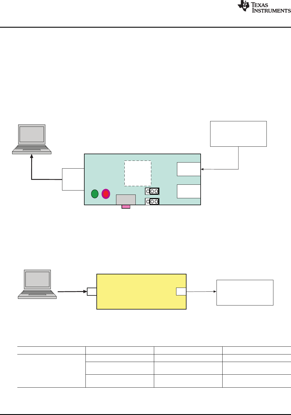
Configure the equipment as shown in Figure 4-2 .
Figure 4-2. DEM-PCM2912A EVM Configuration for Recording Performance Measurement whenRecording Data
To measure recording performance with the recording data, use S/PDIF digital interface output data.Connect the EVM to the AP2 digital analyzer (SYS-2722); for example, as the DEM-PCM2704 EVMshown in Figure 4-3 .
Figure 4-3. DEM-PCM2704EVM Configuration for Recording Performance Measurement with RecordedData
Table 4-4. Line Input Recording Performance
Power Supply Performance Filter Setting DOUT
5.0 V THD+N (–1 dB at 1 kHz) 400 Hz to 20 kHz LP 0.008%
SNR (BPZ input) 400 Hz to 20 kHz LP 92.5 dB+ A-weighting
DR (–60 dB input) 400 Hz to 20 kHz LP 90.5 dB+ A-weighting
Evaluation and Measurements36 SBAU141 – January 2009
Submit Documentation Feedback

Chapter 5SBAU141 – January 2009
Schematic, PCB Layout, and Bill of Materials
This chapter provides the electrical and physical layout information for the DEM-PCM2912A EVM. The billof materials is included for component and manufacturer reference.
Note: Board layouts are not to scale. These are intended to show how the board is laid out; theyare not intended to be used for manufacturing DEM-PCM2912A EVM PCBs.
Topic .................................................................................................. Page
5.1 Schematics .............................................................................. 38
5.2 Printed Circuit Board Layout ...................................................... 39
5.3 Component List ........................................................................ 40
SBAU141 – January 2009 Schematic, PCB Layout, and Bill of Materials 37
Submit Documentation Feedback
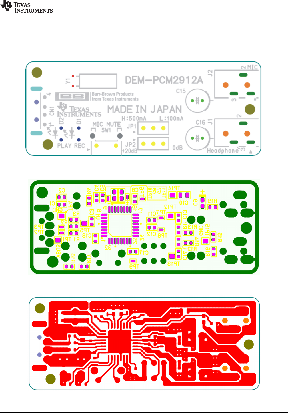
5.2 Printed Circuit Board Layout
www.ti.com
Printed Circuit Board Layout
Figure 5-2 through Figure 5-4 illustrate the printed circuit board (PCB) layout for the DEM-PCM2912AEVM.
Figure 5-2. DEM-PCM2912A EVM Board Layout—Silkscreen
Figure 5-3. DEM-PCM2912A EVM Board Layout—Component Side
Figure 5-4. DEM-PCM2912A EVM Board Layout—Inner View
SBAU141 – January 2009 Schematic, PCB Layout, and Bill of Materials 39
Submit Documentation Feedback

5.3 Component List
Component List
www.ti.com
Table 5-1 lists the bill of materials for the DEM-PCM2912A EVM.
Table 5-1. Bill of Materials
Reference
Designator Value Value2 Manufacturer Mfr Part No Remarks
C1 22 pF 50 V, 5% Taiyoyuden UMK107CH220JZ
C2 22 pF 50 V, 5% Taiyoyuden UMK107CH220JZ
C4 100 pF 50 V, 5% Taiyoyuden UMK107CH101JZ
C5 100 pF 50 V, 5% Taiyoyuden UMK107CH101JZ
C13 0.022 µF 25 V, 10% Taiyoyuden TMK107BJ223KA
C14 0.022 µF 25 V, 10% Taiyoyuden TMK107BJ223KA
C7 0.1 µF 25 V, 10% Taiyoyuden TMK105BJ104KV
C11 1 µF 16 V, 10% Matsushita ECJ-1VB1C105K
C12 1 µF 16 V, 10% Matsushita ECJ-1VB1C105K
C17 1 µF 16 V, 10% Matsushita ECJ-1VB1C105K
C18 1 µF 16 V, 10% Matsushita ECJ-1VB1C105K
C3 1 µF 16 V, 10% Matsushita ECJ-1VB1C105K
C8 1 µF 16 V, 10% Matsushita ECJ-1VB1C105K
C10 3.3 µF 10 V, 10% Murata SS GRM40B335K10PT
C6 10 µF 6.3 V, 20% Rohm TCP0J106M8R
C9 10 µF 6.3 V, 20% Rohm TCP0J106M8R
C15 100 µF 4 V, 20% Matsushita ECE-A0GKS101
C16 100 µF 4 V, 20% Matsushita ECE-A0GKS101
CN1 USB 'A' ACON UAR10-4W5100 Host Interface
D1 LED Rohm SLR342-VR Recording Indicator
D2 LED Rohm SLR342-MG playback Indicator
J1 Stereo mini Jack SMK LGY2502-0200 Stereo Headphone
J2 Stereo mini Jack SMK LGY2502-0200 Mic Input and Bias
R11 16 5% KOA RK73K1J-160J
R12 16 5% KOA RK73K1J-160J
R1 33 5% KOA RK73K1J-330J Should be adjustedto meet USB spec.
R2 33 5% KOA RK73K1J-330J
R17 820 5% KOA RK73K1J-821J
R18 820 5% KOA RK73K1J-821J
R19 1k 5% KOA RK73K1J-102J
R3 1.5k 5% KOA RK73K1J-152J
R13 3.3k 5% KOA RK73K1J-332J
R14 3.3k 5% KOA RK73K1J-332J
R15 3.3k 5% KOA RK73K1J-332J
R16 3.3k 5% KOA RK73K1J-332J
R4 1M 5% KOA RK73K1J-105J
SW1 Tact SW ALPS SKQTLBE010 Mic Mute
U1 PCM2912APJT TI
Y1 Crystal 6 MHz, ±30 ppm Epson CA301 6.000M-C
JP2 Jumper SW Hiroshe denshi A2-3PA2.54DSA(71)
JP3 Jumper SW Hiroshe denshi A2-3PA2.54DSA(71)
40 Schematic, PCB Layout, and Bill of Materials SBAU141 – January 2009
Submit Documentation Feedback

www.ti.com
Component List
Table 5-1. Bill of Materials (continued)
Reference
Designator Value Value2 Manufacturer Mfr Part No Remarks
TP1, Check pin Mac8 HK-4-STP4–TP5,
TP12–TP15
TP2–TP3, Check pin Mac8 HK-6-STP6–TP11
SBAU141 – January 2009 Schematic, PCB Layout, and Bill of Materials 41
Submit Documentation Feedback

EVALUATION BOARD/KIT IMPORTANT NOTICE
Texas Instruments (TI) provides the enclosed product(s) under the following conditions:
This evaluation board/kit is intended for use for ENGINEERING DEVELOPMENT, DEMONSTRATION, OR EVALUATION PURPOSESONLY and is not considered by TI to be a finished end-product fit for general consumer use. Persons handling the product(s) must haveelectronics training and observe good engineering practice standards. As such, the goods being provided are not intended to be completein terms of required design-, marketing-, and/or manufacturing-related protective considerations, including product safety and environmentalmeasures typically found in end products that incorporate such semiconductor components or circuit boards. This evaluation board/kit doesnot fall within the scope of the European Union directives regarding electromagnetic compatibility, restricted substances (RoHS), recycling(WEEE), FCC, CE or UL, and therefore may not meet the technical requirements of these directives or other related directives.
Should this evaluation board/kit not meet the specifications indicated in the User’s Guide, the board/kit may be returned within 30 days fromthe date of delivery for a full refund. THE FOREGOING WARRANTY IS THE EXCLUSIVE WARRANTY MADE BY SELLER TO BUYERAND IS IN LIEU OF ALL OTHER WARRANTIES, EXPRESSED, IMPLIED, OR STATUTORY, INCLUDING ANY WARRANTY OFMERCHANTABILITY OR FITNESS FOR ANY PARTICULAR PURPOSE.
The user assumes all responsibility and liability for proper and safe handling of the goods. Further, the user indemnifies TI from all claimsarising from the handling or use of the goods. Due to the open construction of the product, it is the user’s responsibility to take any and allappropriate precautions with regard to electrostatic discharge.
EXCEPT TO THE EXTENT OF THE INDEMNITY SET FORTH ABOVE, NEITHER PARTY SHALL BE LIABLE TO THE OTHER FOR ANYINDIRECT, SPECIAL, INCIDENTAL, OR CONSEQUENTIAL DAMAGES.
TI currently deals with a variety of customers for products, and therefore our arrangement with the user is not exclusive.
TI assumes no liability for applications assistance, customer product design, software performance, or infringement of patents orservices described herein.
Please read the User’s Guide and, specifically, the Warnings and Restrictions notice in the User’s Guide prior to handling the product. Thisnotice contains important safety information about temperatures and voltages. For additional information on TI’s environmental and/orsafety programs, please contact the TI application engineer or visit www.ti.com/esh .
No license is granted under any patent right or other intellectual property right of TI covering or relating to any machine, process, orcombination in which such TI products or services might be or are used.
FCC Warning
This evaluation board/kit is intended for use for ENGINEERING DEVELOPMENT, DEMONSTRATION, OR EVALUATION PURPOSESONLY and is not considered by TI to be a finished end-product fit for general consumer use. It generates, uses, and can radiate radiofrequency energy and has not been tested for compliance with the limits of computing devices pursuant to part 15 of FCC rules, which aredesigned to provide reasonable protection against radio frequency interference. Operation of this equipment in other environments maycause interference with radio communications, in which case the user at his own expense will be required to take whatever measures maybe required to correct this interference.
EVM WARNINGS AND RESTRICTIONS
It is important to operate this EVM within the input voltage range of –2.0 V to +4.0 V and the output voltage range of –2.0 V to +4.0 V.
Exceeding the specified input range may cause unexpected operation and/or irreversible damage to the EVM. If there are questionsconcerning the input range, please contact a TI field representative prior to connecting the input power.
Applying loads outside of the specified output range may result in unintended operation and/or possible permanent damage to the EVM.Please consult the EVM User's Guide prior to connecting any load to the EVM output. If there is uncertainty as to the load specification,please contact a TI field representative.
During normal operation, some circuit components may have case temperatures greater than +60 °C. The EVM is designed to operateproperly with certain components above +60 °C as long as the input and output ranges are maintained. These components include but arenot limited to linear regulators, switching transistors, pass transistors, and current sense resistors. These types of devices can be identifiedusing the EVM schematic located in the EVM User's Guide. When placing measurement probes near these devices during operation,please be aware that these devices may be very warm to the touch.
Mailing Address: Texas Instruments, Post Office Box 655303, Dallas, Texas 75265Copyright © 2009, Texas Instruments Incorporated

IMPORTANT NOTICE
Texas Instruments Incorporated and its subsidiaries (TI) reserve the right to make corrections, modifications, enhancements, improvements,and other changes to its products and services at any time and to discontinue any product or service without notice. Customers shouldobtain the latest relevant information before placing orders and should verify that such information is current and complete. All products aresold subject to TI’s terms and conditions of sale supplied at the time of order acknowledgment.
TI warrants performance of its hardware products to the specifications applicable at the time of sale in accordance with TI’s standardwarranty. Testing and other quality control techniques are used to the extent TI deems necessary to support this warranty. Except wheremandated by government requirements, testing of all parameters of each product is not necessarily performed.
TI assumes no liability for applications assistance or customer product design. Customers are responsible for their products andapplications using TI components. To minimize the risks associated with customer products and applications, customers should provideadequate design and operating safeguards.
TI does not warrant or represent that any license, either express or implied, is granted under any TI patent right, copyright, mask work right,or other TI intellectual property right relating to any combination, machine, or process in which TI products or services are used. Informationpublished by TI regarding third-party products or services does not constitute a license from TI to use such products or services or awarranty or endorsement thereof. Use of such information may require a license from a third party under the patents or other intellectualproperty of the third party, or a license from TI under the patents or other intellectual property of TI.
Reproduction of TI information in TI data books or data sheets is permissible only if reproduction is without alteration and is accompaniedby all associated warranties, conditions, limitations, and notices. Reproduction of this information with alteration is an unfair and deceptivebusiness practice. TI is not responsible or liable for such altered documentation. Information of third parties may be subject to additionalrestrictions.
Resale of TI products or services with statements different from or beyond the parameters stated by TI for that product or service voids allexpress and any implied warranties for the associated TI product or service and is an unfair and deceptive business practice. TI is notresponsible or liable for any such statements.
TI products are not authorized for use in safety-critical applications (such as life support) where a failure of the TI product would reasonablybe expected to cause severe personal injury or death, unless officers of the parties have executed an agreement specifically governingsuch use. Buyers represent that they have all necessary expertise in the safety and regulatory ramifications of their applications, andacknowledge and agree that they are solely responsible for all legal, regulatory and safety-related requirements concerning their productsand any use of TI products in such safety-critical applications, notwithstanding any applications-related information or support that may beprovided by TI. Further, Buyers must fully indemnify TI and its representatives against any damages arising out of the use of TI products insuch safety-critical applications.
TI products are neither designed nor intended for use in military/aerospace applications or environments unless the TI products arespecifically designated by TI as military-grade or "enhanced plastic." Only products designated by TI as military-grade meet militaryspecifications. Buyers acknowledge and agree that any such use of TI products which TI has not designated as military-grade is solely atthe Buyer's risk, and that they are solely responsible for compliance with all legal and regulatory requirements in connection with such use.
TI products are neither designed nor intended for use in automotive applications or environments unless the specific TI products aredesignated by TI as compliant with ISO/TS 16949 requirements. Buyers acknowledge and agree that, if they use any non-designatedproducts in automotive applications, TI will not be responsible for any failure to meet such requirements.
Following are URLs where you can obtain information on other Texas Instruments products and application solutions:
Products ApplicationsAmplifiers amplifier.ti.com Audio www.ti.com/audioData Converters dataconverter.ti.com Automotive www.ti.com/automotiveDLP® Products www.dlp.com Broadband www.ti.com/broadbandDSP dsp.ti.com Digital Control www.ti.com/digitalcontrolClocks and Timers www.ti.com/clocks Medical www.ti.com/medicalInterface interface.ti.com Military www.ti.com/militaryLogic logic.ti.com Optical Networking www.ti.com/opticalnetworkPower Mgmt power.ti.com Security www.ti.com/securityMicrocontrollers microcontroller.ti.com Telephony www.ti.com/telephonyRFID www.ti-rfid.com Video & Imaging www.ti.com/videoRF/IF and ZigBee® Solutions www.ti.com/lprf Wireless www.ti.com/wireless
Mailing Address: Texas Instruments, Post Office Box 655303, Dallas, Texas 75265Copyright © 2009, Texas Instruments Incorporated
