Thales Defense and Security 4102023501 LAND MOBILE RADIO User Manual Liberty Users Guide
Thales Communications Inc LAND MOBILE RADIO Liberty Users Guide
Contents
- 1. Manual rev
- 2. Revised Manual
Manual rev
LIBERTY
TM
LAND MOBILE RADIO
PRC7332
USER’S GUIDE
APRIL 2009

FRONT MATTER
2 Doc No. 84382 Rev 2
THALES COMMUNICATIONS, INC. PROPRIETARY INFORMATION
! NOTE
LIBERTYTM RADIOS
Please use the following field support contact information:
Contact Info:
Bob DiDonato,
Thales Communications, Inc.
Mobile: 1-410-908-7678
Email: Bob.DiDonato@thalescomminc.com
Scott Glazer,
Thales Communications, Inc.
Mobile: 1-240-422-2612
Email: Scott.Glazer@thalescomminc.com

FRONT MATTER
Doc No. 84382 Rev 2
THALES COMMUNICATIONS, INC. PROPRIETARY INFORMATION iii
COPYRIGHT: APRIL 2009
THALES COMMUNICATIONS, INC.
PUBLISHED AND CONFIDENTIAL WORK
ALL RIGHTS RESERVED
CONFIGURATION NOTICE: This document contains technical information pertinent to the
LibertyTM Radio. The information contained herein is for the support of the LibertyTM Radio.
PROPRIETARY NOTICE: This document contains information proprietary to THALES
COMMUNICATIONS, INC. It is furnished for operation and support purposes only and not for
reprocurement. All reprocurement and manufacturing rights are expressly reserved by THALES
COMMUNICATIONS, INC., and no such use may be made of this document, either directly or
indirectly without the prior written consent of THALES COMMUNICATIONS, INC.
LICENSE AGREEMENTS
This software is licensed solely for use within this product. US Patent Nos. #6,912,495 B2,
#6,199,037 B1, #5,870,405, #5,826,222, #5,754,974, #5,715,365, #5,701,390, #5,649,050,
#5,630,050, #5,630,011, #5,581,656, #5,517,511, #5,491, 772, #5,247,579, #5,226,084, and
#5,195,166.
The AMBE ® voice compression software included in the product is protected by intellectual
property rights including patent rights, copyrights, and trade secrets of Digital Voice Systems,
Inc. The user of this software is explicitly prohibited from attempting to decompile, reverse
engineer, or disassemble the object code, or in any other way convert the object code into a
human-readable form.
! NOTE
This manual contains information that is current as of the
date shown below. Additional functionality is being
developed for the radio and the appearance of operating
screens is subject to change from those shown herein.
Thales Part 84382 Rev 2
April 2009

FRONT MATTER
iv Doc No. 84382 Rev 2
THALES COMMUNICATIONS, INC. PROPRIETARY INFORMATION
RECORD OF CHANGES
Revision Date Description of Change Author
Rev 1 Jan 2009 Initial Pilot Field Trials Version SJA
Rev 2 April 2009 Updated to include scan functions, use of pre-
programmable side buttons, and added FCC information. SJA

FRONT MATTER
Doc No. 84382 Rev 2
THALES COMMUNICATIONS, INC. PROPRIETARY INFORMATION v
TABLE OF CONTENTS
CHAPTER .......................................................................................................................................... PAGE
LICENSE AGREEMENTS ..................................................................................................................................... III
LIST OF FIGURES ................................................................................................................................................. VII
LIST OF TABLES ................................................................................................................................................. VIII
RADIO FREQUENCY ENERGY SAFETY INFORMATION ........................................................................... IX
ELECTROMAGNETIC INTERFERENCE COMPATIBILITY .......................................................................... X
SAFETY SUMMARY .............................................................................................................................................. XI
NOTATIONS USED IN THIS MANUAL ............................................................................................................. XII
FOREWORD ......................................................................................................................................................... XIII
CHAPTER 1 GETTING TO KNOW THE RADIO........................................................................................ 1-1
GENERAL INFORMATION........................................................................................................................................ 1-1
EQUIPMENT CHARACTERISTICS ............................................................................................................................. 1-2
TECHNICAL CHARACTERISTICS ............................................................................................................................. 1-3
LIBERTYTM RADIO – LOCATION OF CONTROLS AND INDICATORS .......................................................................... 1-4
CONTROLS AND INDICATORS ............................................................................................................................... 1-7
CONTROLS ............................................................................................................................................................. 1-7
Special “Hot Keys” .......................................................................................................................................... 1-8
Four-Way Navigation Buttons with Enter Button ............................................................................................ 1-9
Side-Buttons ................................................................................................................................................... 1-10
INDICATORS ......................................................................................................................................................... 1-11
LCD and Keypad Backlight ........................................................................................................................... 1-11
LED Indicators ............................................................................................................................................... 1-11
Connectors ..................................................................................................................................................... 1-12
CHAPTER 2 DISPLAY / MENU SCREENS .................................................................................................. 2-1
GENERAL INFORMATION .................................................................................................................................. 2-1
DISPLAY/ MENU SCREENS ................................................................................................................................ 2-2
SPLASH Screen ............................................................................................................................................... 2-2
HOME Screen .................................................................................................................................................. 2-3
MENU Screen Displays ................................................................................................................................... 2-6
SELECT Menu Screen ..................................................................................................................................... 2-7
VIEW Menu Screen ......................................................................................................................................... 2-8
PROGRAM Menu Screen ................................................................................................................................ 2-9
RADIO INFORMATION Menu Screen ........................................................................................................ 2-18
MAINTENANCE Menu Screen .................................................................................................................... 2-19
CHAPTER 3 OPERATING INSTRUCTIONS ............................................................................................... 3-1
GENERAL INFORMATION........................................................................................................................................ 3-1
OPERATING INSTRUCTIONS .............................................................................................................................. 3-1
Connecting the Battery ..................................................................................................................................... 3-1
Connecting the Antenna ................................................................................................................................... 3-1
Radio Programming ......................................................................................................................................... 3-1
Turning on the Radio ....................................................................................................................................... 3-2
Menu Access .................................................................................................................................................... 3-3
Transmitting ..................................................................................................................................................... 3-4

FRONT MATTER
vi Doc No. 84382 Rev 2
THALES COMMUNICATIONS, INC. PROPRIETARY INFORMATION
Receiving ......................................................................................................................................................... 3-4
P25 Unit to Unit Call ....................................................................................................................................... 3-5
Scanning – Conventional and Priority ............................................................................................................. 3-6
Using the Pre-Programmed Side Buttons ......................................................................................................... 3-8
Modifying Menu Selections – SELECT Menu or PROGRAM Menu ............................................................. 3-9
Changing ZONES ............................................................................................................................................ 3-9
Screensaver .................................................................................................................................................... 3-10
CHAPTER 4 MAINTENANCE ........................................................................................................................ 4-1
GENERAL INFORMATION ........................................................................................................................................ 4-1
OPERATIONAL CHECKOUT ..................................................................................................................................... 4-2
RADIO PREVENTIVE MAINTENANCE ...................................................................................................................... 4-2
Inspection and Cleaning ................................................................................................................................... 4-2
EXTERNAL BATTERY PREVENTIVE MAINTENANCE ............................................................................................... 4-2
TROUBLESHOOTING ............................................................................................................................................... 4-3
REMOVAL/REPLACEMENT PROCEDURES - OPERATOR ........................................................................................... 4-4
Audio Accessory Removal/Replacement . ....................................................................................................... 4-4
Antenna Removal/Replacement. ...................................................................................................................... 4-4
Battery Removal/Replacement. ........................................................................................................................ 4-5
RADIO DISASSEMBLY ............................................................................................................................................ 4-5
CHAPTER 5 BATTERY CHARGERS ............................................................................................................ 5-1
GENERAL INFORMATION .................................................................................................................................. 5-1
PHYSICAL CHARACTERISTICS ................................................................................................................................ 5-2
Weight and Dimensions ................................................................................................................................... 5-2
Temperature ..................................................................................................................................................... 5-2
ELECTRICAL CHARACTERISTICS ............................................................................................................................ 5-2
PERFORMANCE ...................................................................................................................................................... 5-2
OPERATING INDICATIONS ...................................................................................................................................... 5-3
CHAPTER 6 ACCESSORIES AND ANCILLARY EQUIPMENT .............................................................. 6-1
GENERAL ............................................................................................................................................................... 6-1
AVAILABLE ACCESSORIES AND ANCILLARY EQUIPMENT FOR THE LIBERTYTM RADIO ...................................... 6-1
Antennas .......................................................................................................................................................... 6-1
Batteries ........................................................................................................................................................... 6-2
Battery Chargers .............................................................................................................................................. 6-2
Cases / Holsters ................................................................................................................................................ 6-3
Audio Accessories ............................................................................................................................................ 6-3
Cables ............................................................................................................................................................... 6-4
Surveillance Equipment ................................................................................................................................... 6-4
CHAPTER 7 GLOSSARY ................................................................................................................................. 7-1
ACRONYMS’ ...................................................................................................................................................... 7-1
DEFINITIONS .......................................................................................................................................................... 7-2
APPENDIX A – QUICK REFERENCE GUIDE .................................................................................................. 7-1
INDEX ..........................................................................................................................................................INDEX - 1

FRONT MATTER
Doc No. 84382 Rev 2
THALES COMMUNICATIONS, INC. PROPRIETARY INFORMATION vii
LIST OF FIGURES
FIGURE 1-1 LIBERTYTM RADIO ................................................................................................................................... 1-0
FIGURE 1-1 LIBERTYTM RADIO PHYSICAL CHARACTERISTICS .................................................................................... 1-4
FIGURE 1-2 KEYPAD ................................................................................................................................................... 1-7
FIGURE 1-3 LIBERTY SPECIAL “HOT KEYS” ............................................................................................................... 1-8
FIGURE 1-4 FOUR-WAY NAVIGATION BUTTONS WITH ENTER BUTTON ..................................................................... 1-9
FIGURE 1-5 PROGRAMMABLE SIDE BUTTONS ........................................................................................................... 1-10
FIGURE 1-6 LOCATION OF LED ................................................................................................................................ 1-11
FIGURE 1-7 SIDE CONNECTOR .................................................................................................................................. 1-12
FIGURE 1-8 ANTENNA CONNECTOR.......................................................................................................................... 1-13
FIGURE 1-9 BATTERY CONNECTOR .......................................................................................................................... 1-14
FIGURE 2-1 LIBERTYTM HOME SCREEN DISPLAY (SAMPLE) ....................................................................................... 2-2
FIGURE 2-2 DEFAULT “SPLASH” SCREEN ................................................................................................................... 2-2
FIGURE 2-3 LIBERTYTM HOME SCREEN DISPLAY (SAMPLE) ....................................................................................... 2-3
FIGURE 2-4 OPERATING SCREEN – “HOME” SAMPLE SCREEN .................................................................................... 2-4
FIGURE 2-5 OPERATING SCREEN – SOFTKEYS MENU ................................................................................................. 2-5
FIGURE 2-6 SELECT MENU SCREEN ......................................................................................................................... 2-7
FIGURE 2-7 VIEW MENU SCREEN.............................................................................................................................. 2-8
FIGURE 2-8 PROGRAM MENU SCREEN – P25 CHANNEL TYPE ................................................................................. 2-9
FIGURE 2-9 PROGRAM MENU SCREEN – ANALOG NARROWBAND (AN) ............................................................... 2-12
FIGURE 2-10 PROGRAM MENU SCREEN – ANALOG WIDEBAND (AW) ................................................................. 2-14
FIGURE 2-11 RADIO INFORMATION MENU SCREEN ........................................................................................... 2-18
FIGURE 2-12 MAINTENANCE MENU SCREEN ....................................................................................................... 2-19
FIGURE 3-1 RADIO ON/OFF/VOLUME KNOB AND ZONE SELECT ............................................................................. 3-2
FIGURE 3-2 MENU ACCESS ......................................................................................................................................... 3-3
FIGURE 3-3 RADIO ON/OFF/VOLUME KNOB ............................................................................................................. 3-4
FIGURE 3-4 P25 UNIT TO UNIT CALL ......................................................................................................................... 3-5
FIGURE 4-1 MAINTENANCE MENU SCREEN ............................................................................................................... 4-1

FRONT MATTER
viii Doc No. 84382 Rev 2
THALES COMMUNICATIONS, INC. PROPRIETARY INFORMATION
LIST OF TABLES
TABLE 1- 1 EQUIPMENT CHARACTERISTICS ............................................................................................................... 1-2
TABLE 1- 2 TECHNICAL CHARACTERISTICS ............................................................................................................... 1-3
TABLE 1-3 PHYSICAL DESCRIPTION ........................................................................................................................... 1-5
TABLE 1-4 KEYPAD CHARACTERS .............................................................................................................................. 1-8
TABLE 1-5 LED INDICATORS ................................................................................................................................... 1-11
TABLE 2-1 STATUS AREA SYMBOLS ........................................................................................................................... 2-3
TABLE 2-2 CONTEXT AREA DESCRIPTIONS ................................................................................................................ 2-4
TABLE 2-3 SOFTKEY MENU OPTIONS ......................................................................................................................... 2-6
TABLE 2-4 FUNCTIONAL CATEGORY OPTIONS ........................................................................................................... 2-6
TABLE 2-5 SELECT MENU OPTIONS ......................................................................................................................... 2-7
TABLE 2-6 VIEW CHANNEL PARAMETERS .................................................................................................................. 2-8
TABLE 2-7 PROGRAM MENU – P25 CHANNEL TYPE ............................................................................................. 2-10
TABLE 2-8 PROGRAM MENU – ANALOG NARROWBAND (AN) .............................................................................. 2-12
TABLE 2-9 PROGRAM MENU – ANALOG WIDEBAND (AW) .................................................................................. 2-15
TABLE 2-10 CTCSS TONES AND CODES .................................................................................................................. 2-17
TABLE 2-11 CDCSS CODES ..................................................................................................................................... 2-17
TABLE 2-12 MAINTENANCE MENU OPTIONS ....................................................................................................... 2-20
TABLE 3-1 SCAN AND PRIORITY SCAN SIDE BUTTON OPTIONS .................................................................................. 3-7
TABLE 4-1 OPERATOR TROUBLESHOOTING GUIDE .................................................................................................... 4-3
FIGURE 5-1 LIBERTYTM SINGLE-BAY CHARGER ......................................................................................................... 5-1
TABLE 5-2 BATTERY CHARGER WEIGHTS AND DIMENSIONS ..................................................................................... 5-2
TABLE 5-3 CHARGING AND STORAGE TEMPERATURES .............................................................................................. 5-2
TABLE 5-4 CHARGING AND STORAGE TEMPERATURES .............................................................................................. 5-2
TABLE 5-5 CHARGER PERFORMANCE ......................................................................................................................... 5-2
TABLE 5-6 SINGLE-BAY CHARGE STATUS INDICATORS ............................................................................................. 5-3
TABLE 6-1 ANTENNA VERSIONS ................................................................................................................................ 6-1
TABLE 6-2 LIBERTYTM BATTERIES ............................................................................................................................ 6-2
TABLE 6-3 LIBERTYTM BATTERY CHARGERS ............................................................................................................. 6-2
TABLE 6-4 LIBERTYTM CASES / HOLSTERS ................................................................................................................ 6-3
TABLE 6-5 LIBERTYTM AUDIO ACCESSORIES ............................................................................................................. 6-3
TABLE 6-6 LIBERTYTM CABLES ................................................................................................................................. 6-4
TABLE 6-7 LIBERTYTM SURVEILLANCE EQUIPMENT .................................................................................................. 6-4
FRONT MATTER
Doc No. 84382 Rev 2
THALES COMMUNICATIONS, INC. PROPRIETARY INFORMATION ix
RADIO FREQUENCY ENERGY SAFETY INFORMATION
This THALES transceiver has been evaluated and complies with the standards listed below, in regards to
Radio Frequency (RF) energy and electromagnetic energy (EME) generated by the transceiver.
• FCC RF exposure limits for Occupational Use Only. RF Exposure limits adopted by the FCC are
generally based on recommendations from the National Council on Radiation Protection and
Measurements, & the American National Standards Institute.
• FCC OET Bulletin 65 Edition 97-01 Supplement C
• American National Standards Institute (C95.1 . 1992)
• American National Standards Institute (C95.3 . 1992)
WARNING:
This THALES tr
ansceiver generates RF EME while transmitting. RF EME
(Radio Frequency Electric & Magnetic Energy) has the po
tential to cause
slight thermal
or heating effects to any part of your body less than the
recommended distance from this radio transmitter’s antenn
a. RF energy
exposure is determined primarily by the distance to and the power of the
transmitting device. In general, RF exposure is minimized when the lowest
possible power is used or transmission time is kept to the minimum required
for consistent commu
nications, and the greatest distance possible from the
antenna to the body is maintained. The transceiver has been designed for and is
classified for Occupational Use Only. Occupational/ controlled exposure limits
are applicable to situations in which persons are exposed to RF energy as a
consequence of their employment, and such persons have been made aware of
the potential for exposure and can exercise control over their exposure. This
means you can use the transceiver only if you are aware of the potential
hazards of operating a transceiver and are familiar in ways to minimize these
hazards. This transceiver is not intended for use by the general public in
uncontrolled environments. Uncontrolled environment exposure limits are
applicable to situations in
which the general public may be exposed to RF
energy, or in which the persons who are exposed as a consequence of their
employment may not be fully aware of the potential for exposure or cannot
exercise control over their exposure.
The following list provides you with the information required to ensure that you are aware of RF
exposure and of how to operate this transceiver so that the FCC RF exposure limitations are not exceeded.
• Do not transmit for more than 50% of the total transceiver use time; transmitting over 50% of the
total use time may exceed the limits in accordance to the FCC RF exposure requirements.
Nominal transceiver operation is 10% transmission time, 10% reception time, and 80% stand-by
time.
• Use only the specified antenna for this transceiver; this may be either the antenna provided with
the transceiver or another antenna authorized by THALES.
CAUTION
To ensure that your exposure to RF EME is within the FCC limits for
occupational use, you must observe and adhere to the above points.

FRONT MATTER
x Doc No. 84382 Rev 2
THALES COMMUNICATIONS, INC. PROPRIETARY INFORMATION
RF EXPOSURE GUIDELINES
To ensure that exposure to RF electromagnetic energy is within the FCC allowable limits
for occupational use, always adhere to the following guidelines:
• DO NOT operate the radio without a proper antenna attached, as this may damage
the radio and may cause the FCC RF exposure to be exceeded. A proper antenna
is the antenna supplied with the radio or an antenna specifically authorized by
Thales Communications Inc. (Refer to Table 6-1, Antenna Versions)
• ALWAYS use Thales authorized accessories (antenna, batteries, speaker/mic,
etc…). When worn on the body, always place the radio in a Thales recommended
clip or holster meant for this product. The use of other than recommended or
approved body-worn accessories may result in RF exposure levels which exceed
the FCC Occupational/Controlled environment RF exposure limits. (Refer to
Chapter 6 for a complete listing of Available Accessories and Ancillary
Equipment authorized for use on the LibertyTM Radio.
• ALWAYS keep the radio and its antenna away from the body and face when
transmitting to ensure FCC RF exposure compliance requirements are not
exceeded:
Face with NO Accessory
Radio: 2.5 cm
Antenna: 5.5 cm
Body worn using belt clip
Radio: 1.6 cm
Antenna: 2.0 cm
Body worn using belt holster
Radio 2.0 cm
Antenna: 2.2 cm
ELECTROMAGNETIC INTERFERENCE COMPATIBILITY
Electronic devices are susceptible to electromagnetic interference (EMI) if they are not adequately
shielded or designed for electromagnetic compatibility. Because this transceiver generates RF energy,
it can cause interference to such equipment.
• Turn OFF your transceiver where signs are posted to do so. Hospitals and health care facilities
use equipment that is sensitive to electromagnetic radiation.
• Turn OFF your transceiver while on board an aircraft when so instructed. Use of the transceiver
must be in accordance with airline regulations and/or crew instructions.
“OCCUPATIONAL USE ONLY” RADIO
The LibertyTM Radio generates RF electromagnetic energy during transmit mode of
operation. This radio is designed and classified for “Occupational Use Only”, meaning it
must be used only during the course of employment by individuals aware of the hazards
and the ways to minimize such hazards. This radio is NOT intended for use by the
General Population in an uncontrolled environment.
LIBERTYTM RADIO COMPLIANCE WITH FCC PART 15 RULES
This device complies with Part 15 of the FCC Rules. Operation is subject to condition that
this device does not harmful interference.

FRONT MATTER
Doc No. 84382 Rev 2
THALES COMMUNICATIONS, INC. PROPRIETARY INFORMATION xi
SAFETY SUMMARY
The following are general safety precautions that are not related to any specific procedure,
and do not appear elsewhere in this manual. These Safety Summaries are recommended
precautions that all personnel must understand and apply during any given phase of
operation and maintenance. Each chapter has other specific warnings and cautions.
KEEP AWAY FROM LIVE CIRCUITS
Personnel must at all times observe all safety regulations. Do not replace components or
make adjustments inside equipment with power turned on. Under certain conditions,
dangerous voltages may exist when the power switch is in the off position due to charges
retained by capacitors. To avoid injury, always remove power and discharge and ground a
circuit before touching it.
VOLTAGES WITHIN THIS EQUIPMENT ARE HIGH ENOUGH TO
ENDANGER LIFE.
(Applies to battery chargers only)
Covers are not to be removed except by persons qualified and authorized to do so and
these persons should always take extreme care once the covers have been removed.
HAZARDS OF ELECTROMAGNETIC RADIATION TO ORDNANCE (HERO)
DO NOT operate the radio within 27 feet (8 meters) of any type of fuzed ordnance.
Operating the radio in close proximity to ordnance MAY induce or otherwise couple
currents and/or voltages of magnitudes large enough to initiate electro-explosive devices
or other sensitive explosive components of weapon systems, ordnance, or explosive
devices.
CAUTION - LITHIUM ION BATTERIES
Li-ion batteries have a very high energy density. Exercise precaution when handling and
testing. Do not short circuit, overcharge, crush, mutilate, nail penetrate, apply reverse
polarity, expose to high temperature or disassemble. High case temperature resulting from
abuse could cause physical injury.
REPAIRS, ALTERATIONS TO EQUIPMENT
Repairs to this equipment should be made only by an authorized technician or facility
designated by Thales. Any repairs, alterations, or substitutions of recommended parts
made by the user to this equipment not approved by the manufacturer could void the user’s
authority to operate the equipment in addition to Thales’s Warranty.
FRONT MATTER
xii Doc No. 84382 Rev 2
THALES COMMUNICATIONS, INC. PROPRIETARY INFORMATION
NOTATIONS USED IN THIS MANUAL
Throughout this manual, there are WARNING, CAUTION, or NOTE Statements that emphasize safety
hazards, or care that should be observed.
WARNING:
A WARNING Statement is an operation procedure,
practice, or other condition that might result in injury or
death if not carefully observed. Do not proceed beyond a
WARNING symbol until the conditions identified are fully
understood or met.
CAUTION
A CAUTION Statement indicates an operational procedure,
practice or other condition, which, if not performed
correctly or adhered to, could result in a risk of danger,
damage to the equipment, or severely degrade equipment
performance.
! NOTE
A NOTE Statement that calls attention to supplemental
information that may improve system performance or
clarify a process or procedure.
FRONT MATTER
Doc No. 84382 Rev 2
THALES COMMUNICATIONS, INC. PROPRIETARY INFORMATION xiii
FOREWORD
! NOTE
The radio operation (man-machine interface) shown in this
manual reflect Radio Software Version 70 and PC
Programmer Version 00.00.01.14. Some screens do not
correspond to those in earlier radio software or PC
Programmer versions.
The organization of the LibertyTM User’s Guide is as follows:
a. Chapter 1 Getting to Know the Radio. This chapter provides general information for the
LibertyTM Radio including equipment description and purpose.
b. Chapter 2 Display / Menu Screens – This chapter covers information covering the various
displays / menu screens that can be found on the radio.
c. Chapter 3 Operating Instructions – This chapter describes the operating instructions for the
radio.
d. Chapter 4 Maintenance - This chapter provides instructions required for on-equipment and off-
equipment preventive and corrective maintenance of the LibertyTM Radio.
e. Chapter 5 Battery Chargers – This chapter provides a brief overview on the operation of the
chargers .
f. Chapter 6 Accessories / Ancillaries – This chapter provides a complete listing of accessories and
ancillaries used with the LibertyTM Radio.
g. Chapter 7 Glossary - The glossary provides a definition of the special terms and acronyms used
in this document.
h. Index
i. Attachments –
Quick Reference Guide (QRG)
GETTING TO KNOW THE RADIO
1-0 Doc No. 84382 Rev 2
THALES COMMUNICATIONS, INC. PROPRIETARY INFORMATION
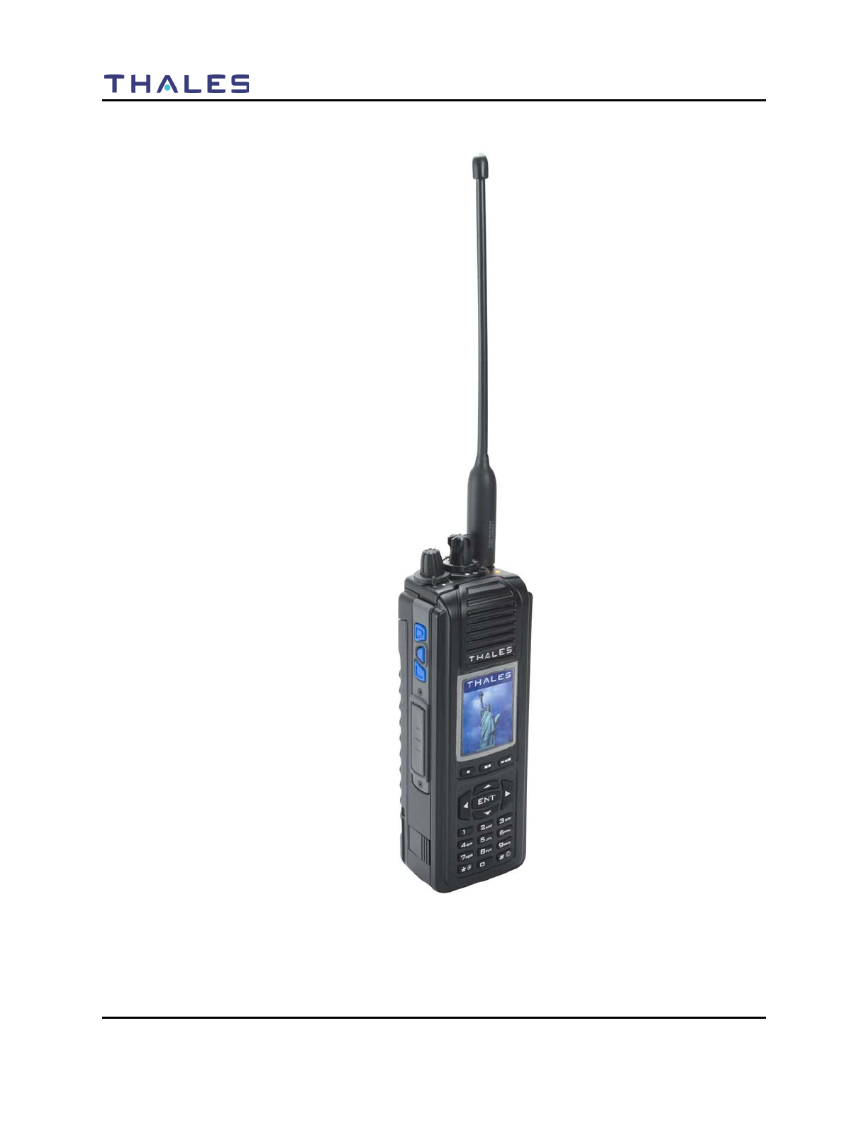
Figure 1-1 LibertyTM Radio

GETTING TO KNOW THE RADIO
Doc No. 84382 Rev 2
THALES COMMUNICATIONS, INC. PROPRIETARY INFORMATION 1-1
CHAPTER 1 GETTING TO KNOW THE RADIO
Description Page Number
General Information 1-1
Equipment Characteristics 1-2
Technical Characteristics 1-3
LibertyTM Radio – Location of Controls and Indicators 1-4
Controls and Indicators 1-7
Controls 1-7
Special “Hot Keys” 1-8
Four Way Navigation Buttons with ENT Button 1-9
Indicators 1-10
LCD and Keypad Backlight 1-11
LED Indicators 1-11
Connectors 1-12
GENERAL INFORMATION
The LibertyTM Multi-Band Radio is a portable, hand-held, battery operated transceiver capable of
providing both secure and non-secure communications.
The radio is software upgradeable in the field, and selected features are capable of being enabled and
disabled on a per radio basis. In addition, multiple software loads will be available with encryption
support added or removed.
The LibertyTM Multi-Band radio is designed to provide Public Safety communications, both voice and
data, in the following frequency bands
• VHF (136-174 MHz),
• UHF (380-520 MHz),
• 700 MHz (763-775/793-805 MHz), and
• 800 MHz (806/851-824/869 MHz)
The LibertyTM Radio is designed to be extremely easy-to-use and programmable intuitively via either
Keypad or PC.
The LibertyTM Radio consists of the following items:
• LibertyTM Multi-band portable radio
• Multi-band Antenna
• Lithium-Ion Battery
GETTING TO KNOW THE RADIO
1-2 Doc No. 84382 Rev 2
THALES COMMUNICATIONS, INC. PROPRIETARY INFORMATION
• Standard Battery Charger
• Belt Clip
EQUIPMENT CHARACTERISTICS
Table 1- 1 Equipment Characteristics
Characteristics Specification
Modes of Operation • Analog 12.5/25 kHz
• P25 Digital (12.5 kHz), Conventional
• P25 Trunking (Future)
Channel Spacing • 12.5 / 25 kHz channels
• 2.5 / 3.125 kHz Frequency Increments
Frequency Stability • 1.5 ppm (-30°C (22°F ) to + 60°C (140°F))
Interoperability • Legacy Analog FM Radios
• P25 Digital Radios
• P25 Trunking Systems (Future)
Programmable Channels
Initial Release • 1 banks (Groups of Zones)
• 16 Zones (up to 256 Channels)
• User Programmable from
o Front Panel Menu
o
PC Programmer
Production Release • Up to 2608 Conventional Channels or Trunked Talkgroups
(Any Combinations)
• 10 banks (Groups of Zones)
• 175 Zones (up to 16 channels / talkgroups each)
• 3 additional event zones with up to 16 channels / talkgroups
each)
• User Programmable from
o Front Panel Menu
o PC Programmer
o Radio to Radio Cloning
• Clear / Encrypted Selection on a Channel-by-Channel or
Talkgroup Base
• Password Protected to Limit Access

GETTING TO KNOW THE RADIO
Doc No. 84382 Rev 2
THALES COMMUNICATIONS, INC. PROPRIETARY INFORMATION 1-3
TECHNICAL CHARACTERISTICS
Table 1- 2 Technical Characteristics
Characteristics Specification
Weight LibertyTM Radio including battery ~28 ounces (794 grams)
Dimension 2.5” W x 1.9” D x 7” L (excluding antenna and knobs)
6.4cm W x 4.8cm D x 17.8 cm L (excluding antenna and knobs)
Operating Temperature (-30°C* (22°F ) to + 60°C (140°F))
(*cold starts below -25°C may require a 3 minute warm-up for
full specification compliance)
Storage Temperature Low Temperature – minimum of -40°C (-40°F) for 24 hours
High Temperature -- maximum of 85°C (+85°F) for 24 hours
Operational Low Pressure 15,000 feet operational
Storage Low Pressure Exposure to storage at 30,000 ft.
Charging Temperature 0°C (32°F) to + 45°C (113°F)
Rechargeable Battery Operating
Temperature Range -20°C (-4°F) to + 60°C (140°F)
Rated Power UHF – 5W
VHF – 5W
700 MHz – 2.5W
800 MHz – 3.0W
GETTING TO KNOW THE RADIO
2-4 Doc No. 84403 Rev 2
THALES COMMUNICATIONS, INC PROPRIETARY INFORMATION
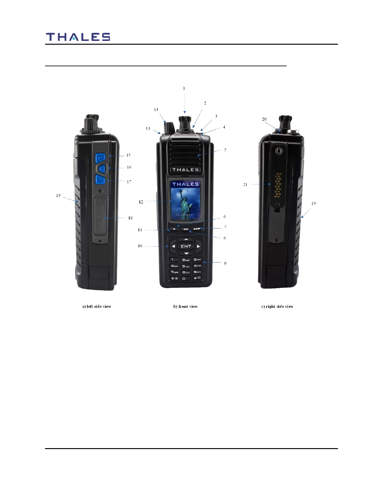
LIBERTYTM RADIO – LOCATION OF CONTROLS AND INDICATORS
The LibertyTM Radio Physical Features are as shown in the figure below.
Figure 2-1 LibertyTM Radio Physical Characteristics
GETTING TO KNOW THE RADIO
Doc No. 84382 Rev 2
THALES COMMUNICATIONS, INC. PROPRIETARY INFORMATION 1-5
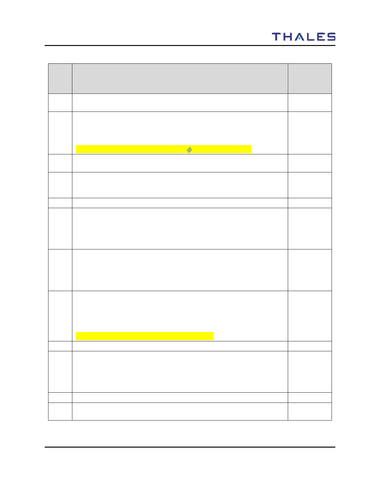
Table 1-3 Physical Description
Item
No. Description
Programmed
by PC
Programmer
1 Channel Switch – This switch can be programmed to select any 16 settings,
(not all positions need be programmed).
2 2-Position Programmable Switch – Although often referred to as the
“Encryption Switch”, this switch is actually a programmable switch. This
switch can be programmed to select any two settings. There is no “typical”
setting for this switch.
Current Version -- EXT/INT Audio (“ ” EXT and “0” INT)
3 Antenna connector – Antenna connects to the radio here for TX and RX of
RF signals.
4 Status LED – Used to visually indicate various states of the radio. May be
solid RED, GREEN, or YELLOW-ORANGE, or flashing individual
colors or combinations of colors, depending on the radio state.
5 Speaker – radio internal speaker
6 Programmable Soft-key Button 1 – This button activates the feature or
function displayed immediately above it on the color display. Additional
entries are accessed by scrolling through the selections using the left/right
navigation buttons. The features on the display can be programmed to
select any programmable function of the radio.
7 Programmable Soft-key Button 3 – This button activates the feature or
function displayed immediately above it on the color display. Additional
entries are accessed by scrolling through the selections using the left/right
navigation buttons. The features on the display can be programmed to
select any programmable function of the radio.
8 Programmable Soft-key Button 2 – This button activates the feature or
function displayed immediately above it on the color display. Additional
entries are accessed by scrolling through the selections using the left/right
navigation buttons. The features on the display can be programmed to
select any programmable function of the radio.
Current Version – Locked to PRIV Call on P25
9 Keypad – Used to enter alpha-numeric and symbols similar to a cell phone.
10 4-Way Navigation Buttons with Enter – UP/DOWN/LEFT/RIGHT/ENTER
buttons used to navigate around the Color Display and highlight displayed
icons or fields. The ENTER button is used to “enter” the feature
highlighted, which may be a menu, a programming option, or other function
as programmed into the radio.
11 Microphone – radio internal microphone
12 Color Display – Color LCD for the display of radio status and other
information.

GETTING TO KNOW THE RADIO
1-6 Doc No. 84382 Rev 2
THALES COMMUNICATIONS, INC. PROPRIETARY INFORMATION
Item
No. Description
Programmed
by PC
Programmer
13 3-Position Programmable Switch – This switch can be programmed to
select any three settings. Typically, this switch is programmed for 3-
different Zones/Groups.
Current Version – Locked to Zones 1, 2, and 3.
14 ON/OFF/Volume Control Knob – Used to turn the radio ON & OFF, and to
control the volume level for the internal speaker when the radio is on. The
most counter-clockwise position, (first position), is radio OFF; the next
clockwise position, (second position), is radio ON with the internal speaker
muted; the next 14 clockwise positions, (positions 3 through 16), are radio
ON while sequencing through the lowest to highest volume settings on the
internal speaker.
15 Side Button 1 – This button can be programmed to select any feature.
Current programmable functions are : Disabled, Ni/Low Power, Monitor,
Scan, Priority Scan, and Talkaround.
16 Side Button 2 – This button can be programmed to select any feature
Current programmable functions are : Disabled, Ni/Low Power, Monitor,
Scan, Priority Scan, and Talkaround.
17 Side Button 3 – this button can be programmed to select any feature.
Current programmable functions are : Disabled, Ni/Low Power, Monitor,
Scan, Priority Scan, and Talkaround.
18 PTT (Push-to-Talk) Button – Press and Hold button used to initiate a call,
i.e., transmit on a channel.
19 Battery – Provides DC power to the radio.
20 Emergency Button – Although commonly referred to as the “Emergency
Button”, this PRESS & Hold button is actually a programmable button.
This button can be programmed to cause the radio to enter any radio
feature/state. Typically, this button is programmed to cause the radio to
enter into an “Emergency” mode of operation.
21 Side Connector – Used to connect to accessories and devices, PC
Programmer (i.e., PC), KFD, etc.
Note: A “” indicates that this function is programmable via the PcProgrammer.
GETTING TO KNOW THE RADIO
Doc No. 84382 Rev 2
THALES COMMUNICATIONS, INC. PROPRIETARY INFORMATION 1-7
CONTROLS AND INDICATORS
CONTROLS
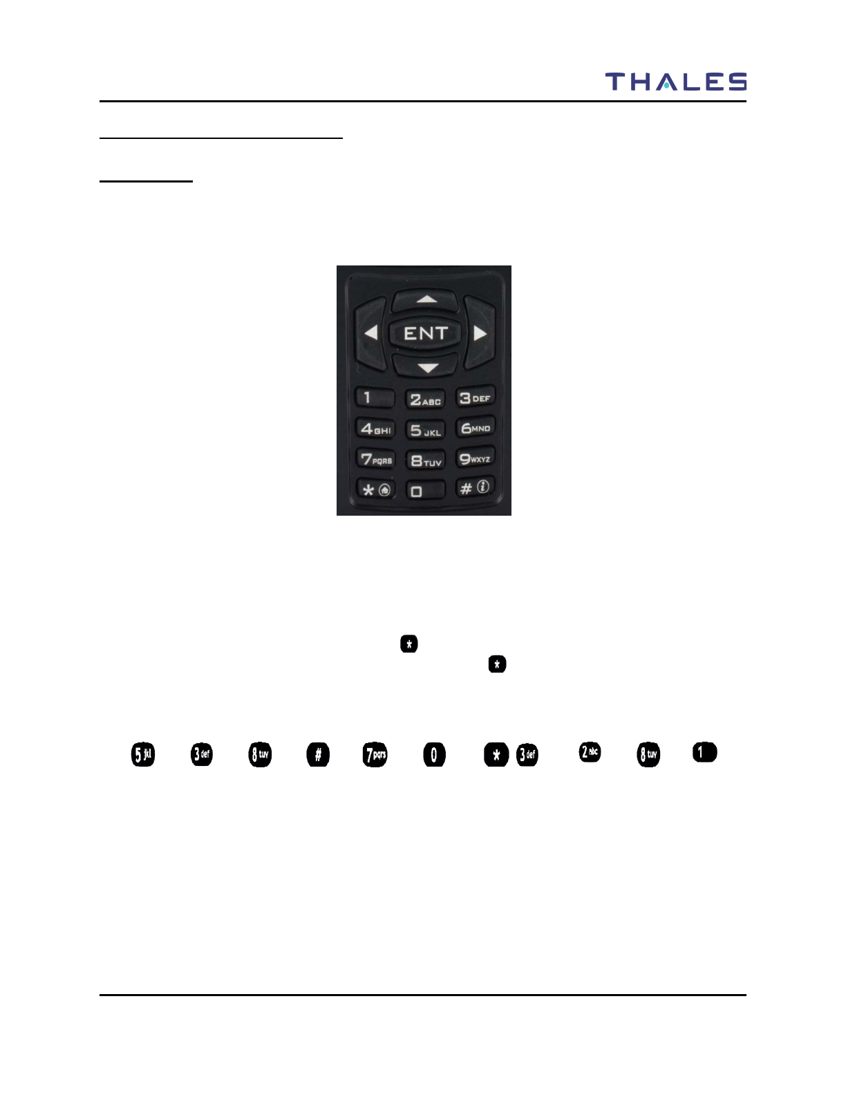
The keypad (Refer to Figure 1-2) for the radio provides an interface to the radio’s features. The keypad
functions are similar to a standard cell phone or telephone keypad when entering numeric digits.
Figure 1-2 Keypad
When the keypad is used to edit a list, each key can generate different characters of the alphabet (refer to
Table 1-4 or a complete list of keypad characters.) By default, the first letter in each word will
automatically be capitalized; the remaining letters in the word will automatically be lower case.
However, the user may override this by pressing to switch between upper case, lower case, and
automatic case. To select the case of an individual letter, press before pressing the key. If the entry
being edited is a numeric, such as frequency, then the keypad will generate only numbers.
For example:
L e t ‘ s e a t .
GETTING TO KNOW THE RADIO
1-8 Doc No. 84382 Rev 2
THALES COMMUNICATIONS, INC. PROPRIETARY INFORMATION
Table 1-4 Keypad Characters
Key Number times the key is pressed
1 2 3 4 5 6 7 8 9
Space 0 ! ? , ; : ( )
. 1 / - + < = >
A B C 2
D E F 3
G H I 4
J K L 5
M N O 6
P Q R S 7
T U V 8
W X Y Z 9
Switches
letter
case
# * & " ' % $
Special “Hot Keys”
Figure 1-3 Liberty Special “Hot Keys”
ENT Button
GETTING TO KNOW THE RADIO
Doc No. 84382 Rev 2
THALES COMMUNICATIONS, INC. PROPRIETARY INFORMATION 1-9
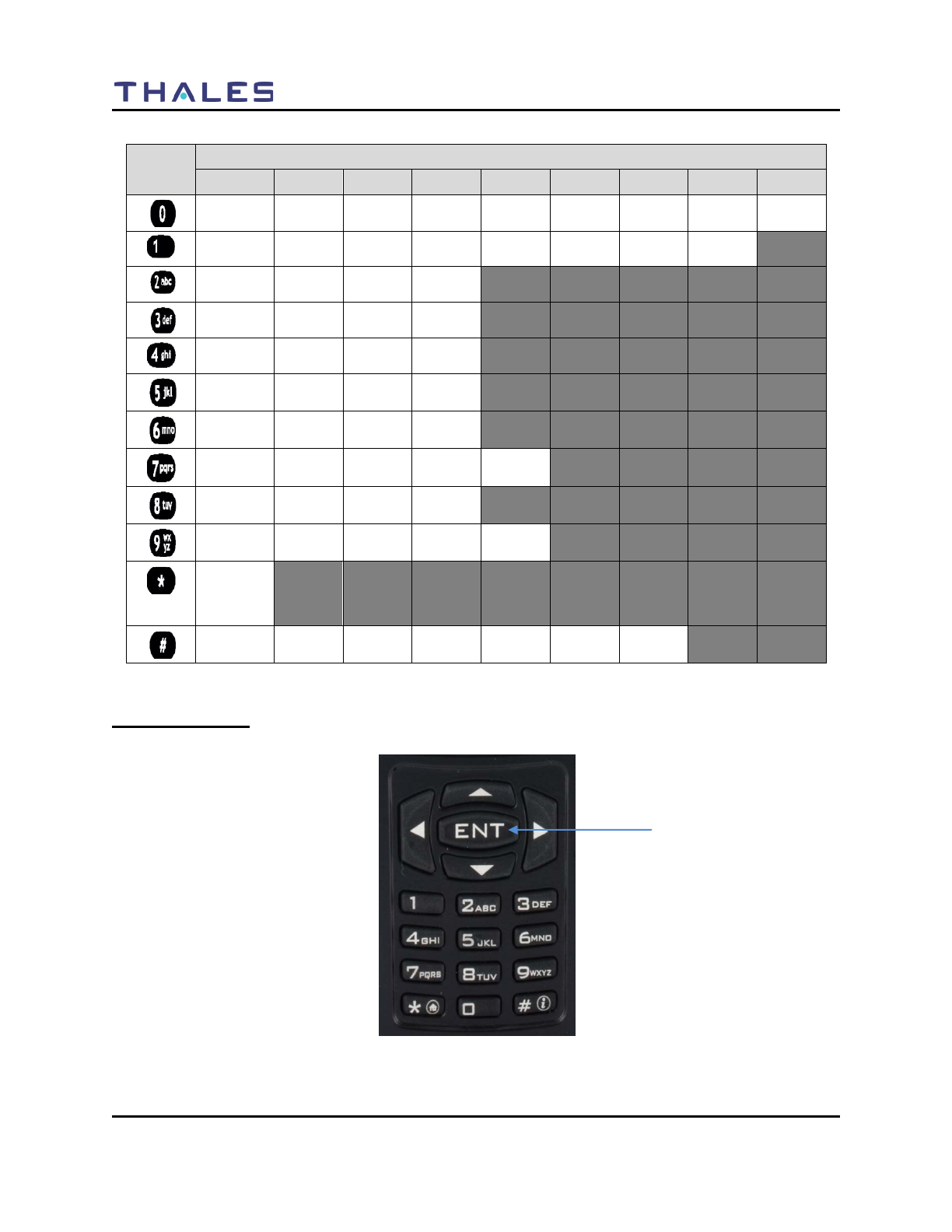
ENT Button
While on the MAIN Screen – and only on this screen – the ENT button (refer to Figure 1-3) on the
Navigation keypad acts as a hotkey to display the SELECT MENU screen.
• Pressing and holding the ENT hotkey button for more than ½ second displays the SELECT
MENU Screen.
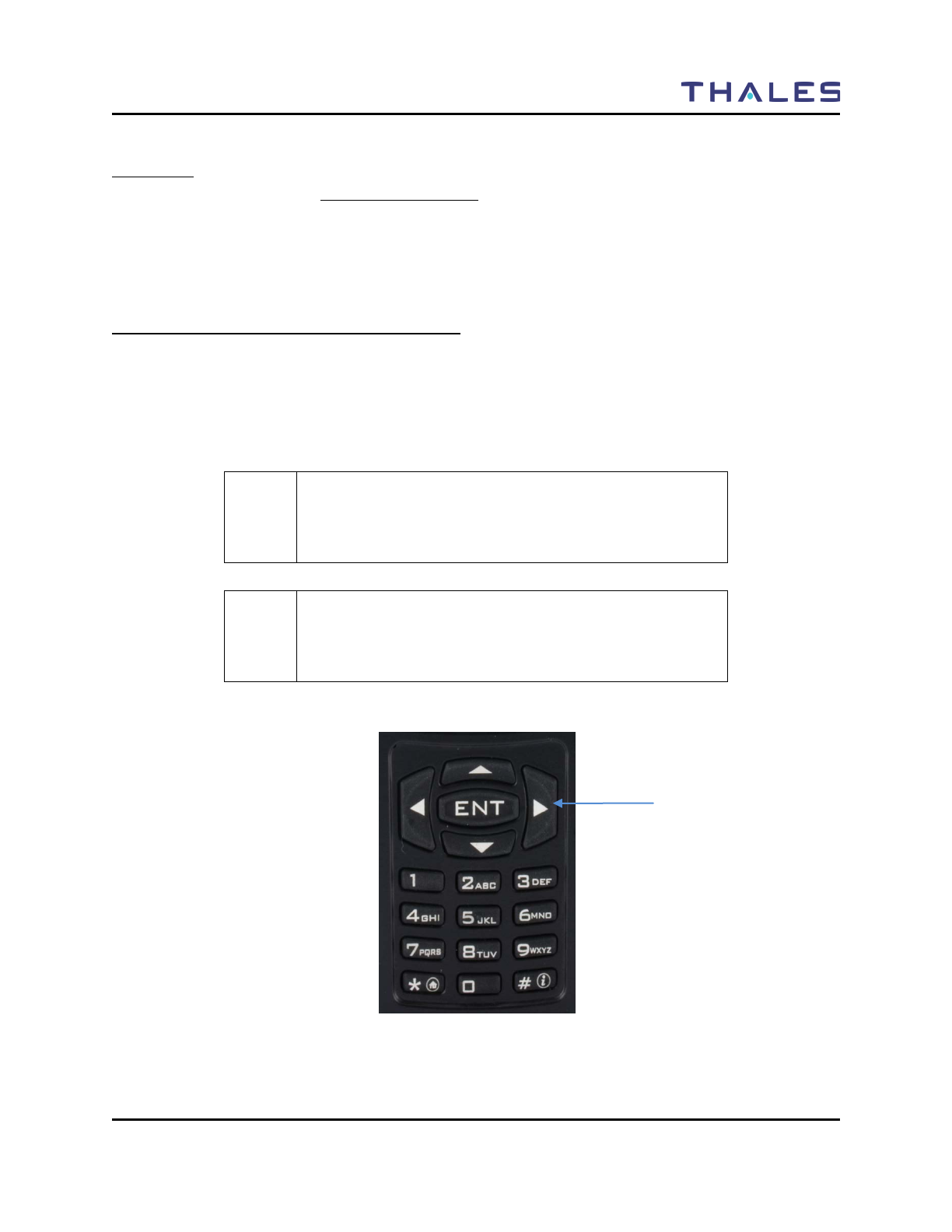
Four-Way Navigation Buttons with Enter Button
The Navigation, (Left/Right/Up/Down) (refer to Figure 1-4), buttons are used to scroll through the radio’s
lists, or items in the display, or both.
When an item/icon is highlighted, the ENT button – in the center of the Navigation buttons – is used to
enter the highlighted function or screen.
! NOTE
When the OPERATING/MAIN Screen is displayed, the
ENT button functions as a “hotkey” short-cut to the
SELECT MENU Screen.
! NOTE
The screen names “MAIN” and “OPERATING” and
“HOME” are used interchangeably throughout this
document.
Figure 1-4 Four-Way Navigation Buttons with Enter Button
Navigational Keys
GETTING TO KNOW THE RADIO
1-10 Doc No. 84382 Rev 2
THALES COMMUNICATIONS, INC. PROPRIETARY INFORMATION
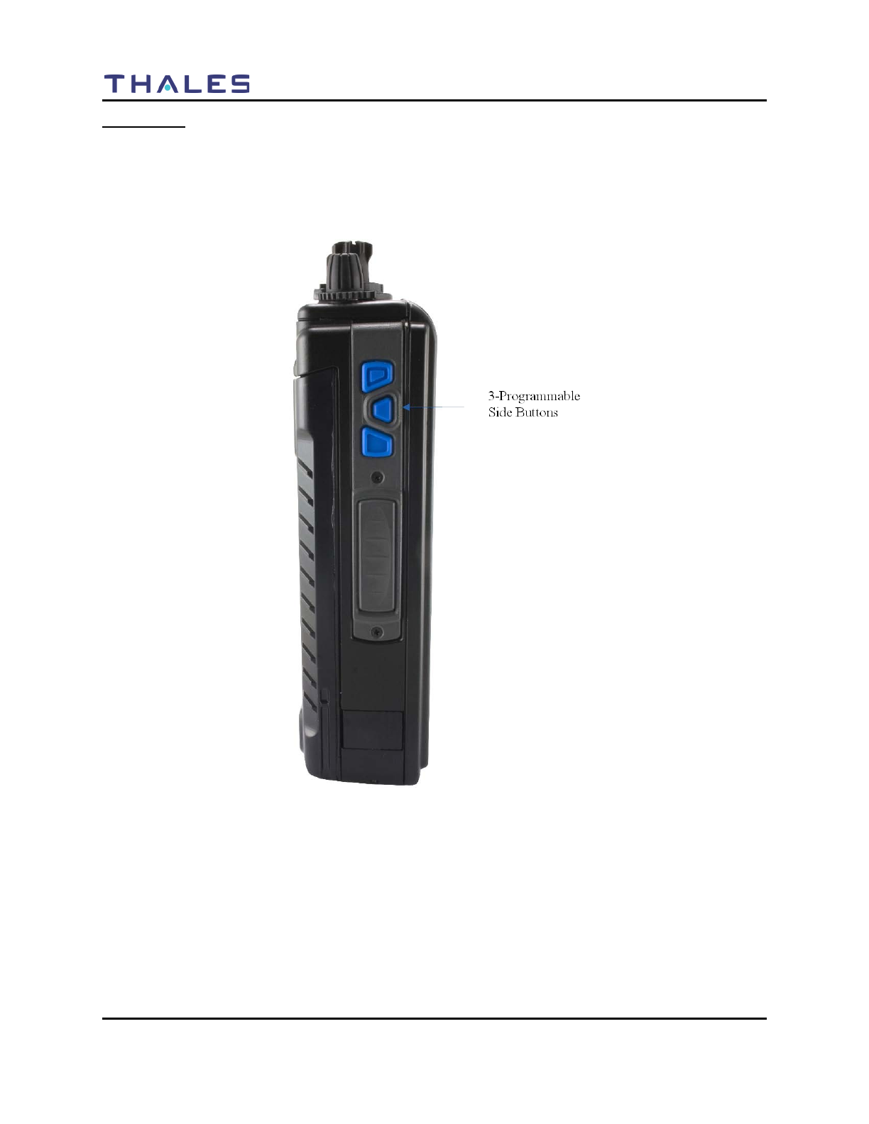
Side-Buttons
The three (3) side buttons (refer to Figure 1-5), can be preprogrammed to select variety of features.
Programming is achieved using the PcProgrammer. Currently, these buttons can each be set for Hi/Low
Power, Monitor, Scan, Priority Scan, or Talk Around.
Figure 1-5 Programmable Side Buttons
GETTING TO KNOW THE RADIO
Doc No. 84382 Rev 2
THALES COMMUNICATIONS, INC. PROPRIETARY INFORMATION 1-11
INDICATORS
LCD and Keypad Backlight
The user may turn on the backlighting for the display, keypad, and channel numbers (around the
16-position Select knob), by pressing any key or button. These lights will remain on for a pre-
determined time period before they turn off automatically.
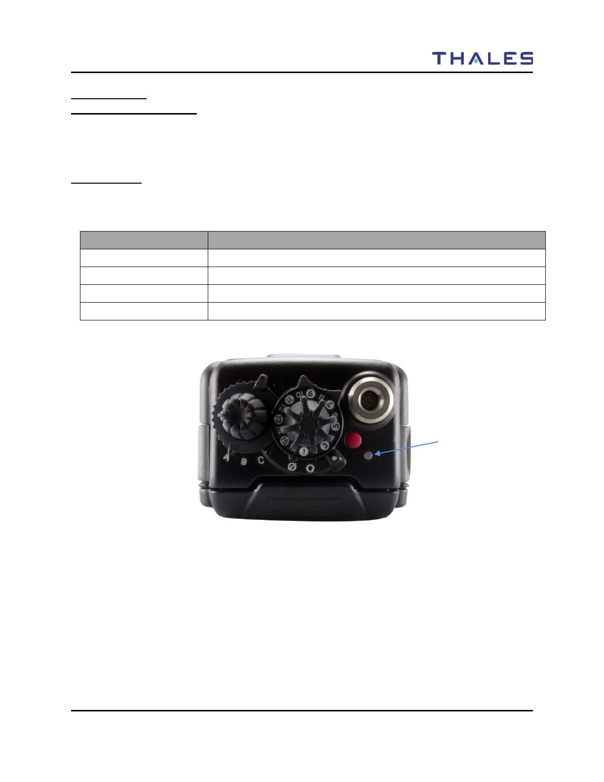
LED Indicators
The LED on the top of the radio indicates the radio’s operating status.
Table 1-5 LED Indicators
LED Indicator What it Means
RED Radio Transmitting
Flashing RED Low Battery (while transmitting)
GREEN Receiving/Busy Channel Indication
OFF Standby
Figure 1-6 Location of LED
LED Indicator
GETTING TO KNOW THE RADIO
1-12 Doc No. 84382 Rev 2
THALES COMMUNICATIONS, INC. PROPRIETARY INFORMATION
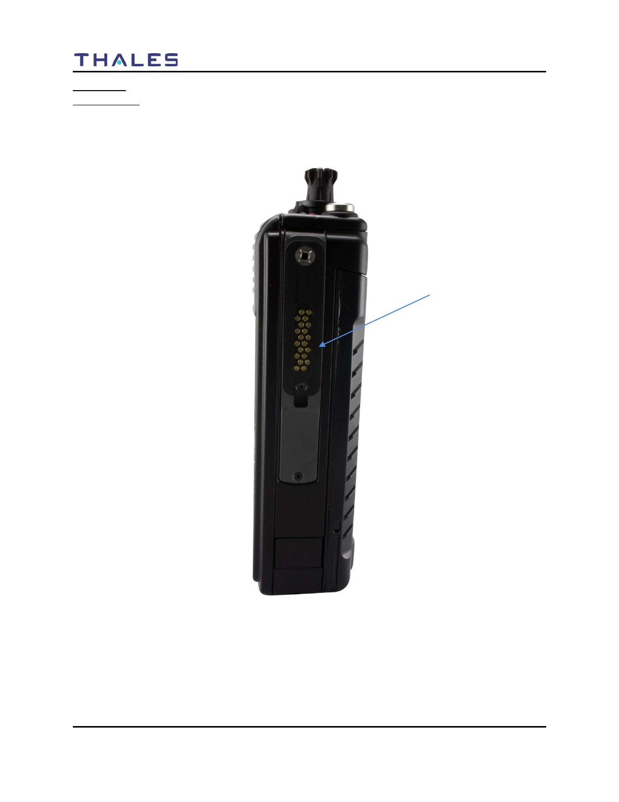
Connectors
Side Connector
The side connector (Refer to Figure 1-7) is a 20-pin connector located on the right side of the radio. This
connector is used for multiple functions, including interfacing with the Radio Programmer, Accessories,
Cloning and Data Mode cables.
Figure 1-7 Side Connector
Side Connector
GETTING TO KNOW THE RADIO
Doc No. 84382 Rev 2
THALES COMMUNICATIONS, INC. PROPRIETARY INFORMATION 1-13
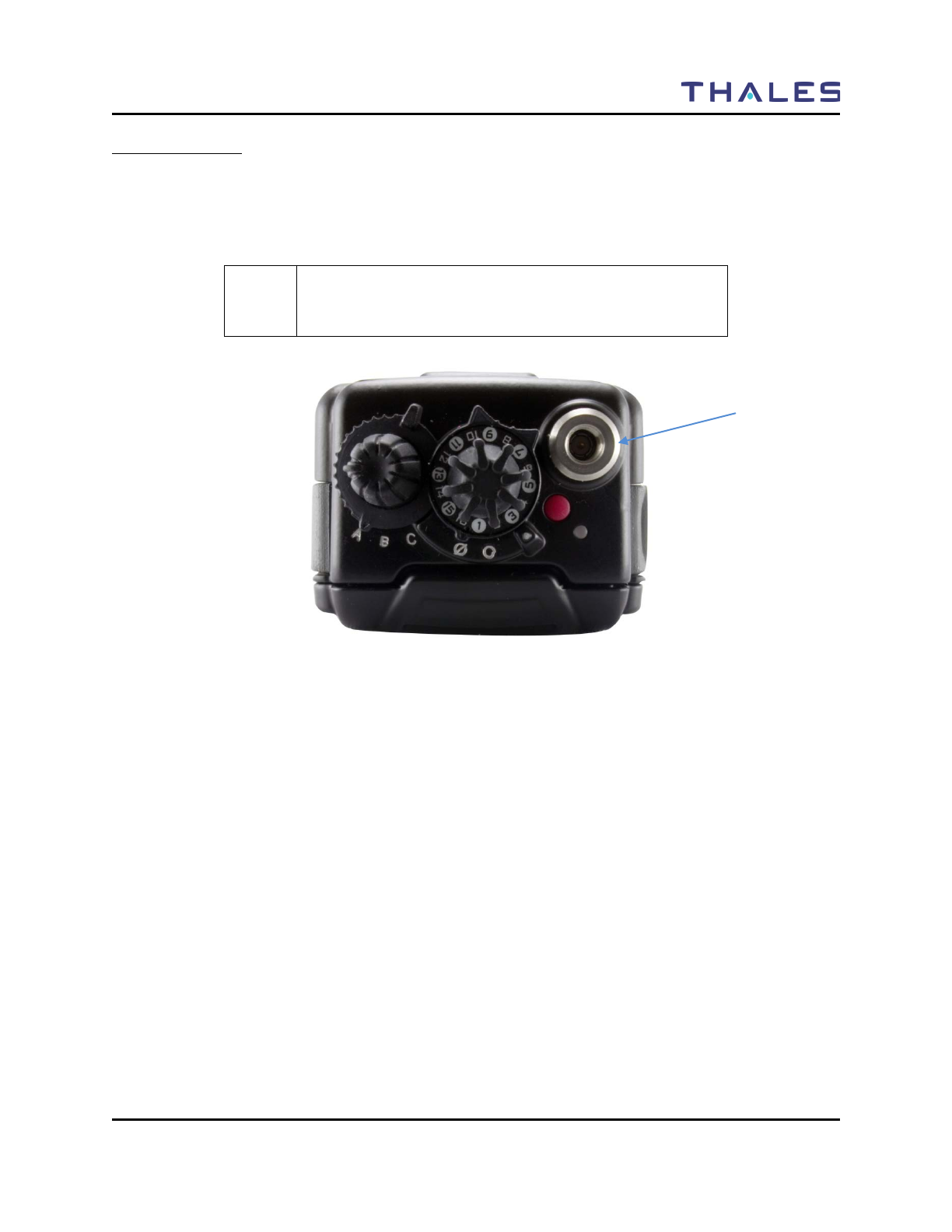
Antenna Connector
The antenna connector (Refer to Figure 1-8) is a male type connector on the top of the radio. It is
recommended that an antenna ALWAYS be connected to the radio when transmitting, even though the
radio includes protective circuits to prevent damage from transmitting without an antenna. An antenna
should be connected whenever the radio is immersed.
! NOTE
It is recommended that an antenna ALWAYS be connected
to the radio when transmitting.
Figure 1-8 Antenna Connector
Antenna Connector
GETTING TO KNOW THE RADIO
1-14 Doc No. 84382 Rev 2
THALES COMMUNICATIONS, INC. PROPRIETARY INFORMATION
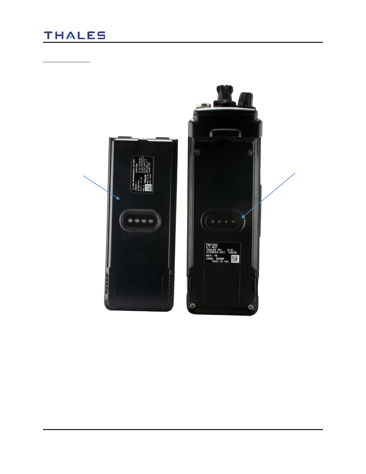
Battery Connector
The battery connector is a 4-pin connector located on the back of the radio. The battery is connected to the
radio by inserting the top of the battery under the flap at the top of the radio and snap down into place.
Figure 1-9 Battery Connector
Battery Connector
Underside of Battery

DISPLAY / MENU SCREENS
Doc No. 84382 Rev 2
THALES COMMUNICATIONS, INC. PROPRIETARY INFORMATION 2-1
CHAPTER 2 DISPLAY / MENU SCREENS
GENERAL INFORMATION
This section describes the Display / Menu Screens of the radio. This chapter contains the following:
Description Page Number
General Information 2-1
Display / Menu Screens 2-2
SPLASH Screen 2-2
HOME Screen 2-3
MENU Screen Display 2-6
SELECT Menu Screen 2-7
VIEW Menu Screen 2-8
PROGRAM Menu Screen 2-9
Channel Type - P25 2-9
Channel Type – Analog Narrowband (AN) 2-12
Channel Type – Analog Wideband (AW) 2-14
RADIO INFORMATION Menu Screen 2-18
MAINTENANCE Menu Screen 2-19
DISPLAY / MENU SCREENS
2-2 Doc No. 84382 Rev 2
THALES COMMUNICATIONS, INC. PROPRIETARY INFORMATION
DISPLAY/ MENU SCREENS
The LibertyTM radio display consists of a color QVGA liquid crystal display (LCD). After the initial
power-up sequence, the overall display is shown in
Figure 2-1. It is divided into three distinct regions as shown in
Figure 2-1.
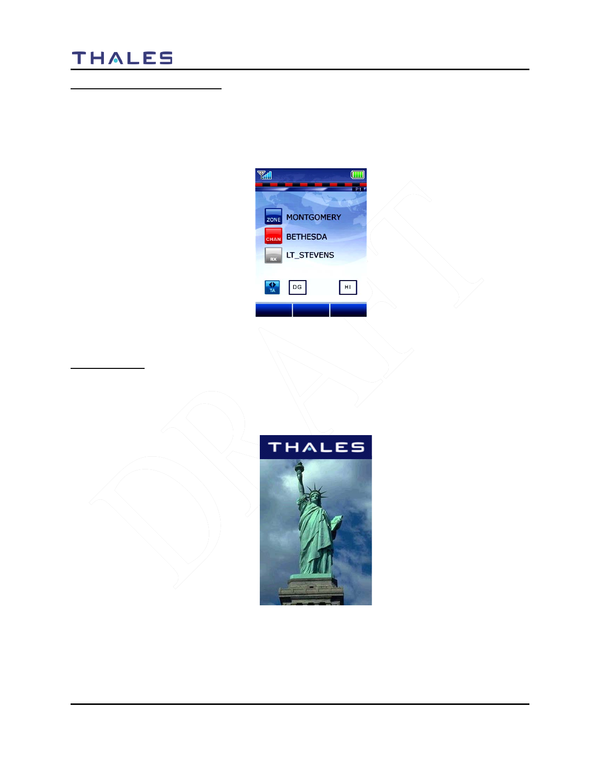
Figure 2-1 LibertyTM Home Screen Display (Sample)
SPLASH Screen
Immediately upon powering on the radio, a SPLASH screen (Figure 2-2) is displayed. The SPLASH
screen appears, or “fades in”, first the picture, followed by the “THALES” logo, followed by the
“Slogan”, and finally the Version. This screen is displayed while the radio is executing its Power-Up
sequence.
Figure 2-2 Default “Splash” Screen
GIVE ME LIBERTY
TM
VERSION
00
.
00
MENU
PRIV
BAKLIT
DISPLAY / MENU SCREENS
Doc No. 84382 Rev 2
THALES COMMUNICATIONS, INC. PROPRIETARY INFORMATION 2-3
The makeup of this screen is:
• Status Area – displays the Thales Logo horizontally centered in the center of the Status Area on a
DARK BLUE Background.
• Context Area – displays a “Power-Up” picture.
• Softkeys Area – displays a Thales inspired slogan, such as “GIVE ME LIBERTYTM” and the
LibertyTM Version information.
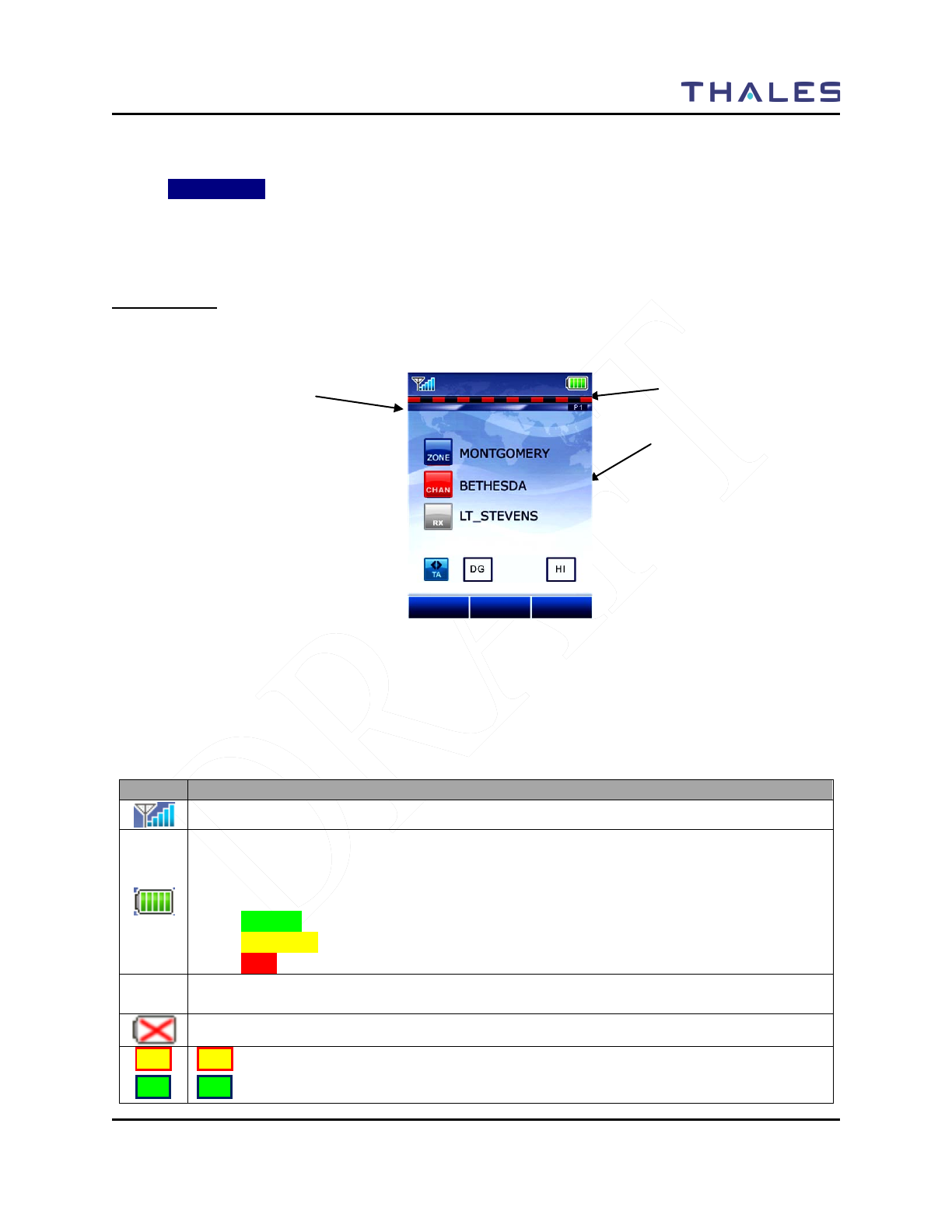
HOME Screen
The Home Screen (refer to Figure 2-3) is the first screen that is displayed after the radio has completed its
Power-Up Sequence.
Figure 2-3 LibertyTM Home Screen Display (Sample)
The operating screen contains three separate areas –
Status Area– The area contains symbols that indicate various radio operating conditions. Refer to Table
2-1 for a complete breakdown of these symbols and their meanings.
Table 2-1 Status Area Symbols
Symbol
Indication
Received Signal Strength Indication (RSSI) (FUTURE)
Battery
Conventional ⇒ flashes when battery is low
Smart ⇒ the number of bars shown indicate the charge remaining in the battery, flashes
when the battery is low. The color also changes to indicate general state:
• GREEN – Good to Full Charge
• YELLOW – Marginal charge
•
RED – little if any charge left
Monitor (CSQ) - The selected channel is being monitored during conventional operation
only.
Battery – No Connection with Radio
HI
LO
HI = High TX power setting (Default)
LO = Low TX power setting
Status Area
Context Area
SoftKeys Area
MENU
PRIV
TLKARND
DISPLAY / MENU SCREENS
2-4 Doc No. 84382 Rev 2
THALES COMMUNICATIONS, INC. PROPRIETARY INFORMATION
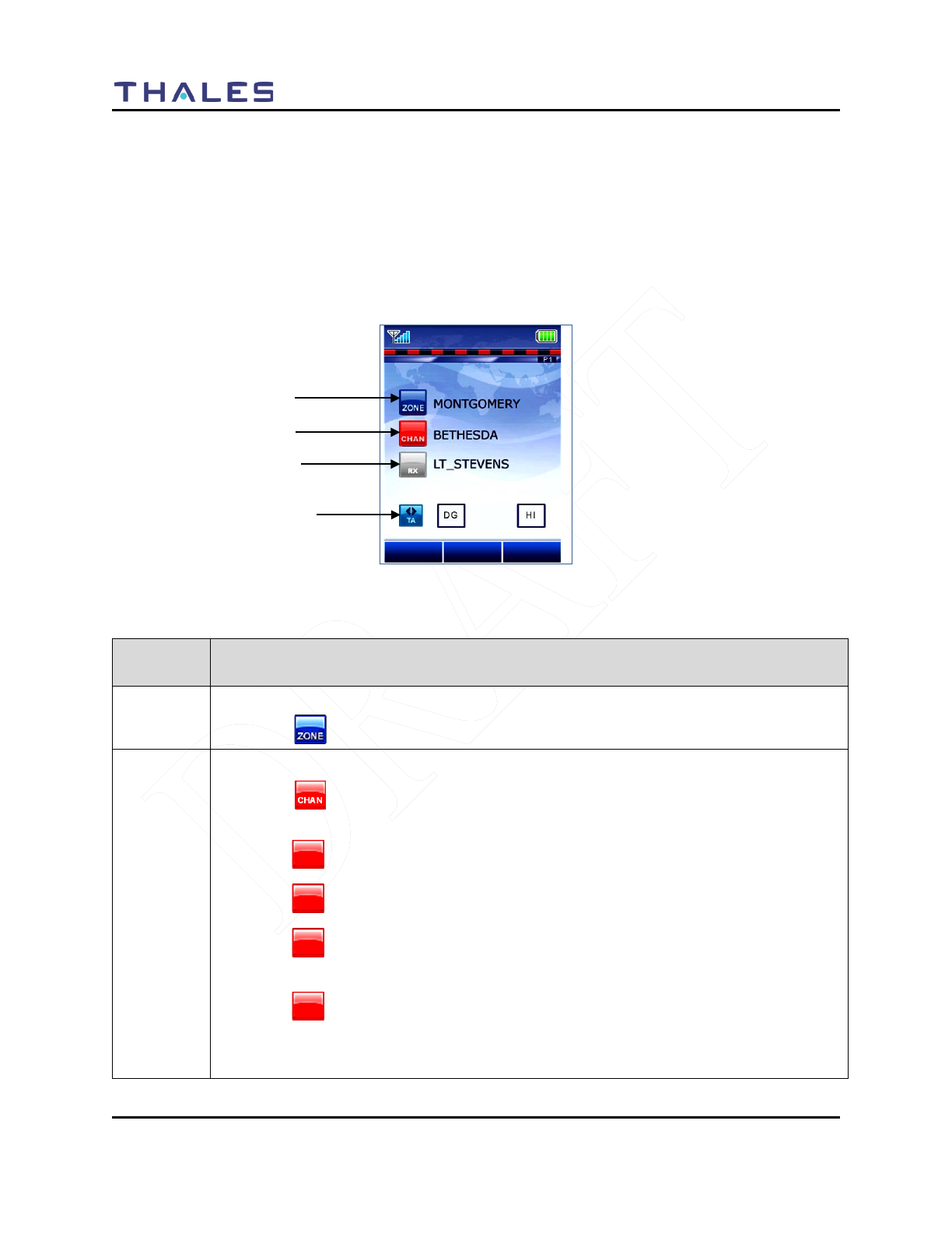
Context Area – The Context Area of the Operating screen provides the status of the radio’s current
operation, including:
– Current Zone Name
– Current Channel Name
– Zone and Group information
– Communication Mode (Talk Around or Repeater)
– Channel Type (AN, AW, P25)
Figure 2-4 Operating Screen – “Home” Sample Screen
Table 2-2 Context Area Descriptions
Context
Area Details
Line #1 Indicates the current selected ZONE name.
• A icon is displayed at the beginning of this line to indicate the current zone.
Line #2
Indicates the current selected Channel/Talkgroup Name.
• A icon is displayed at the beginning of this line to indicate the current
channel.
• A icon indicates that the channel is operating in UHF frequency range.
• A icon indicates that the channel is operating in VHF frequency range.
• A icon indicates that the channel is operating in the 700 MHz frequency
range.
• A icon indicates that the channel is operating in the 800 MHz frequency
range.
The user may toggle this zone channel scan selection using the softkeys.
800
CHAN
700
CHAN
VHF
CHAN
UHF
CHAN
MENU
PRIV
BAKLIT
Context Area – Line #1
Context Area – Line #2
Context Area – Line #3
Context Area – Line #4
DISPLAY / MENU SCREENS
Doc No. 84382 Rev 2
THALES COMMUNICATIONS, INC. PROPRIETARY INFORMATION 2-5
Context
Area Details
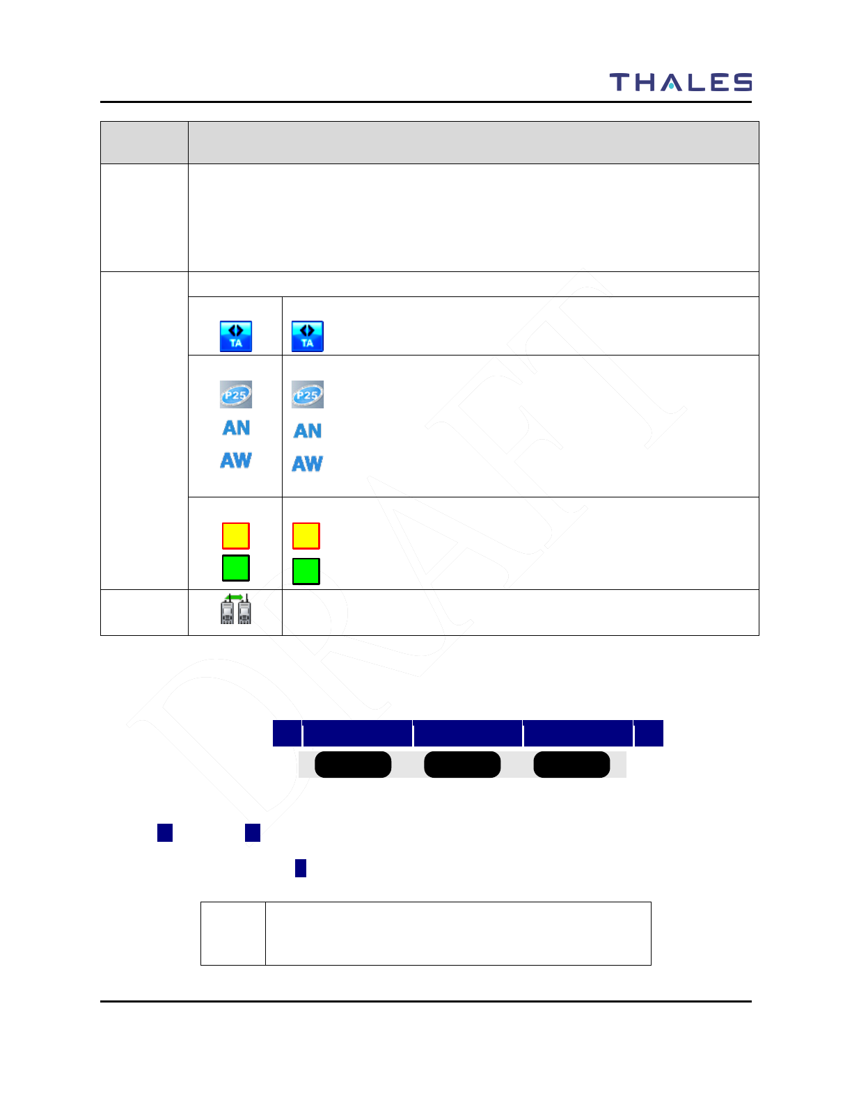
Line #3 Indicates the presence of an active received channel. The icon shall appear when an
active receive carrier is detected and received. This entire row text string is also held for
5.0 seconds after the RX carrier is removed while the radio returns to standby state. If a
new call is received, this line is updated to reflect the new receive channel. If the user
PTT’s the radio, this line is cleared.
Line #4 This line contains four (4) symbols
Indicates the following:
= Talk-around Mode
Indicates the following:
= P25 Mode
= Analog Narrowband
= Analog Wideband
Indicates the following:
= HI TX power setting (Default)
= Low Tx power setting
Individual Call or Page/call Alert Call Received.
Flashes when an individual call is received.
SoftKeys Area – The Softkeys Area of the “OPERATING”, shall display one row of softkeys situated
directly above the 3 softkey button as shown in Figure 2-5 .
◄
MENU
PRIV
BAKLIT
►
Figure 2-5 Operating Screen – Softkeys Menu
The left (◄) and right (►) arrows indicate that there are more softkey selections programmed that can be
displayed by scrolling left or right. If there are no more softkey selections available, the left and right
arrows do not appear; instead a symbol appears.
! NOTE
The BOLD values in the parentheses are the defaults for
each softkey.
VHF
HI
LO
HI
LO
■ ■ ■ ■ ■ ■
DISPLAY / MENU SCREENS
2-6 Doc No. 84382 Rev 2
THALES COMMUNICATIONS, INC. PROPRIETARY INFORMATION
Table 2-3 Softkey Menu Options
Softkey Option Description
MENU Changes the display to the SELECT Menu Screen
PRIV Changes the display to the P25 Individual Call Contact List in order to make or to
cancel an P25 Individual Call. It can also be used to make a Unit to Unit Call.
BAKLIT Turns backlight -- (ON/OFF)
MENU Screen Displays
Once you hit the MENU and the SELECT menu screen appears, the left (◄) and right (►) arrows
allows navigation between each screens, by paging left or right.
Table 2-4 Functional Category Options
Functional Category Description
Programming
PROGRAM – RED
Information/Maintenance VIEW, INFORMATION, MAINTENANCE –BLUE
Selection SELECT – GREEN
The Softkey Menu entry SAVE is used to save the changes made on any selection or programming
screen. If the softkey below SAVE is pressed, the current changes are saved and displayed. If the softkey
below SAVE is pressed and held for 2.0 seconds, the current data is saved and the curser returned to the
top tab so that the menu screens may be scrolled without scrolling to the top.
The Softkey Menu entry EXIT is used to return to the MAIN OPERATING / HOME Menu Screen.
DISPLAY / MENU SCREENS
Doc No. 84382 Rev 2
THALES COMMUNICATIONS, INC. PROPRIETARY INFORMATION 2-7
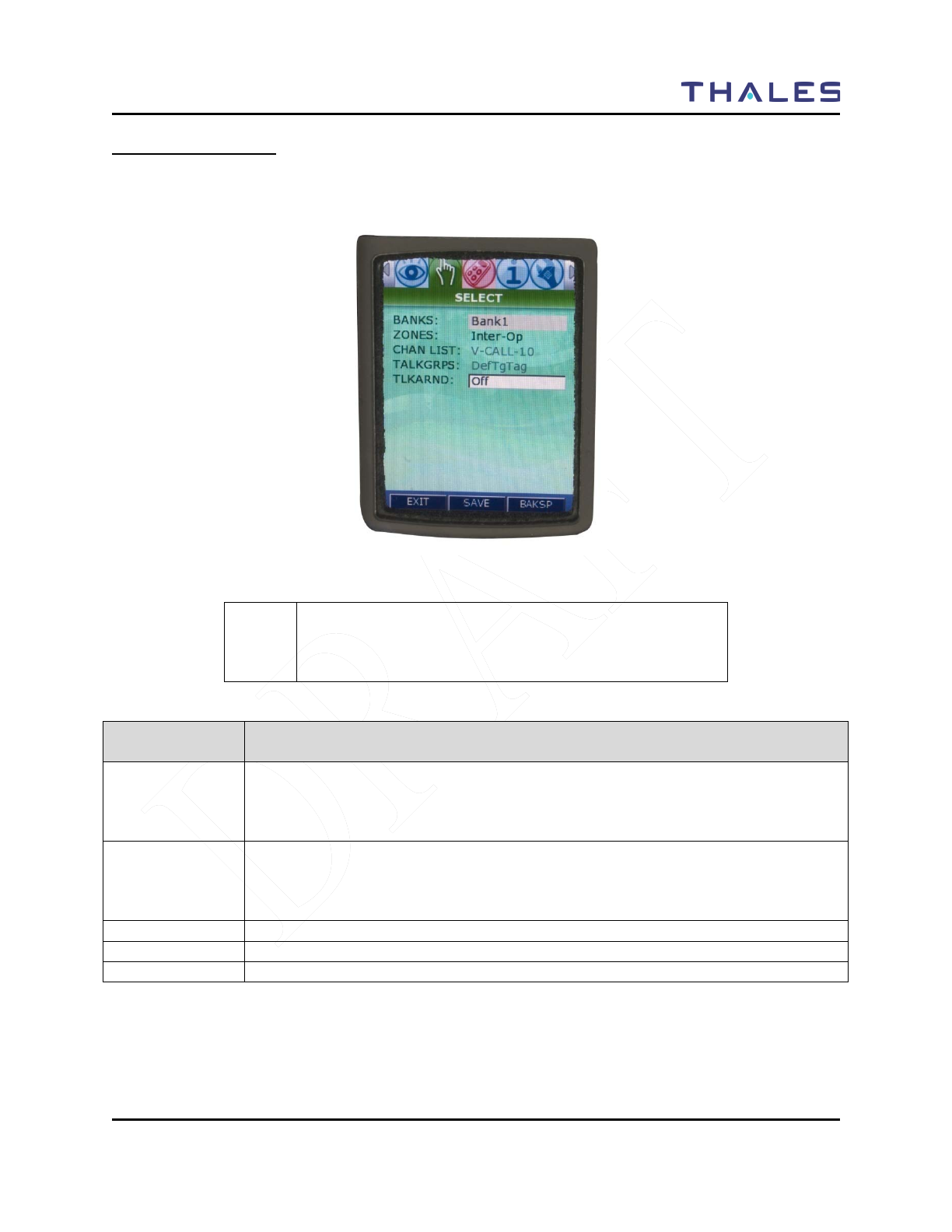
SELECT Menu Screen
When highlighted on the Menu Screen, the SELECT Menu Screen is displayed as a window selection list
as shown in Figure 2-6. The Up/Down Navigation Keys are used to scroll through the available
selections.
Figure 2-6 SELECT Menu Screen
!
NOTE
Currently, the Channel List and Talk Groups on this screen
are grayed out. To change channels, use the Channel Knob
located on top of the radio.
Table 2-5 SELECT Menu Options
Channel
Parameters
Description of function
BANK
This election allows the user to select a Bank from a drop down list as the active
Bank. The Bank selection reverts to the default Bank if the battery is removed for an
extended time. When BANK is selected and ENT is pressed, a drop down list
appears will appear containing a listing of the BANK selections.
ZONE
This selection allows the user to select a Zone corresponding to the active/selected
Bank. The Zone selection replaces the toggle switch setting if programmed for zone
switching. When ZONE is selected and ENT is pressed, a drop down list appears
containing the list of ZONE selections.
CHAN LIST
Lists the current channel name.
TALKGRPS
Displays the current talk group.
TLKARND
This selection allows the user to turn ON or OFF talk-around.
DISPLAY / MENU SCREENS
2-8 Doc No. 84382 Rev 2
THALES COMMUNICATIONS, INC. PROPRIETARY INFORMATION
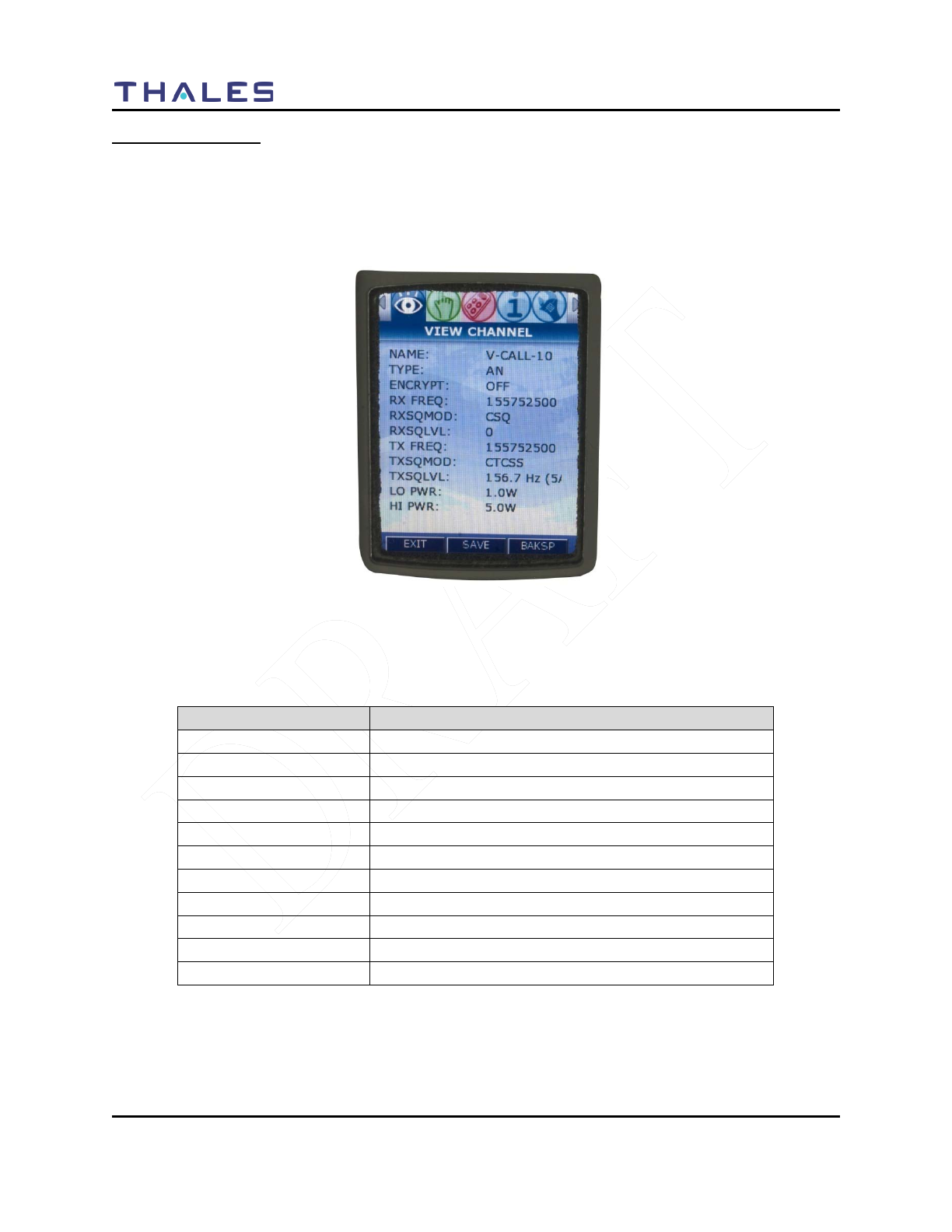
VIEW Menu Screen
The VIEW Menu Screen allows the user to view the parameter settings for the selected channel or
Talkgroup. Reprogramming is not permitted on this screen. The channel is determined by the channel
knob on the top of the radio. While in this screen, changing the channel knob position changes the
displayed parameters to reflect the settings for the selected channel. The displayed parameters are shown
in Figure 2-7.
Figure 2-7 VIEW Menu Screen
The displayed channel parameters are defined as follows:
Table 2-6 View Channel Parameters
Channel Parameters
Description
Name
Channel / Talk-Group Name
Type
Waveform (AN/AW/P25)
Encrypt
OFF / AES / DES
RX Freq
xxx.xxxxx
RX SQ Mode
Receive Squelch Mode
RX SQ Level
Receive Squelch Level
TX Freq
xxx.xxxxx
TX SQ Mode
Transmit Squelch Mode
TX SQ Level
Transmit Squelch Level
LO PWR
Displays Power Level
HI PWR
Displays Power Level
DISPLAY / MENU SCREENS
Doc No. 84382 Rev 2
THALES COMMUNICATIONS, INC. PROPRIETARY INFORMATION 2-9
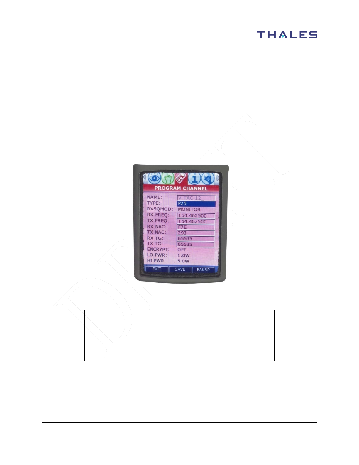
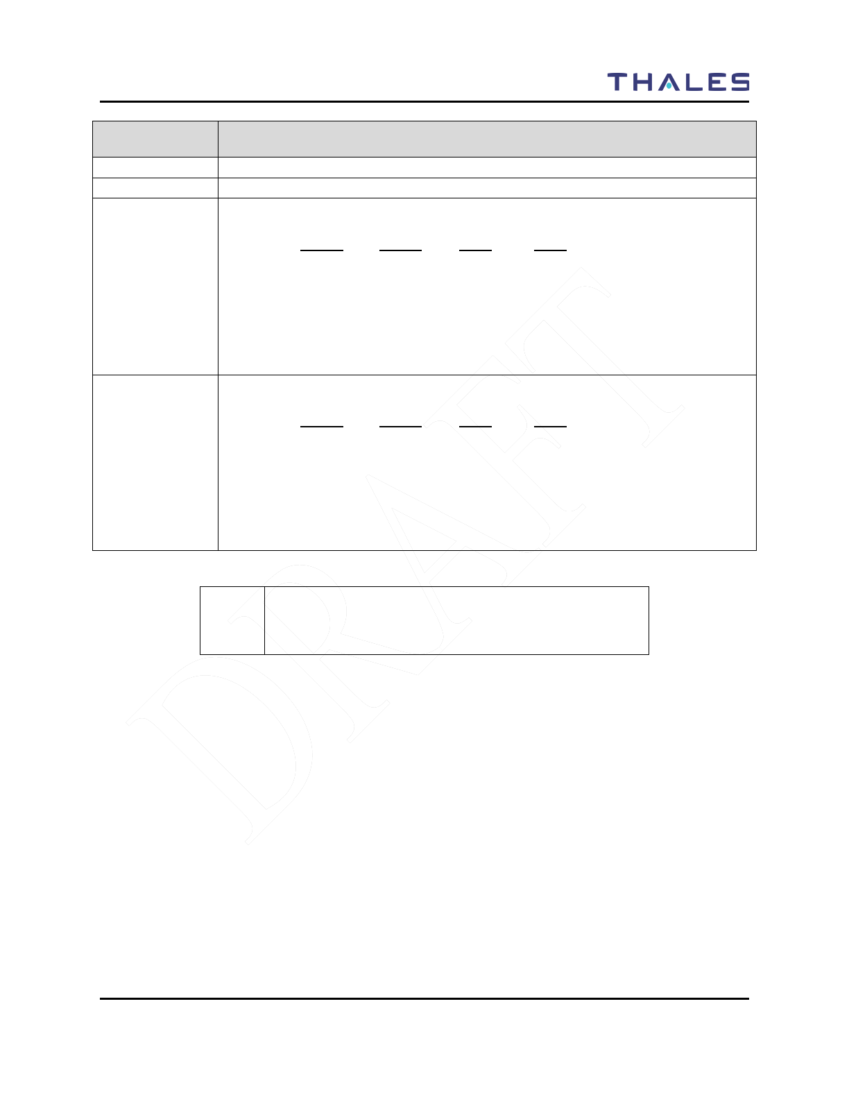
PROGRAM Menu Screen
The PROGRAM Menu Screen (Figure 2-8) allows the user to program the parameter settings for the
selected channel.
The Up/Down Navigation Keys are used to scroll through the available selections. The displayed
parameters are shown in Figure 2-8 for P25, Figure 2-9 for Analog Narrowband (AN) and Figure 2-10 for
Analog Wideband (AW).
The Channel is selected by using the channel knob on the top of the radio. While in this screen, changing
the channel knob position changes the displayed parameters to reflect the parameter settings for the
channel selected by the channel knob.
Channel Type - P25
Figure 2-8 PROGRAM Menu Screen – P25 Channel Type
! NOTE
Only the parameters that are programmable for the selected
TYPE are displayed. For example, ENCRYPT has no
meaning for Analog; therefore, ENCRYPT is not displayed
if the TYPE is either AN (Analog Narrowband) or AW
(Analog Wideband).

DISPLAY / MENU SCREENS
2-10 Doc No. 84382 Rev 2
THALES COMMUNICATIONS, INC. PROPRIETARY INFORMATION
Table 2-7 PROGRAM Menu – P25 Channel Type
Channel
Parameters
Description
NAME
Displays the Channel Name.
TYPE
This selection provides the user with the ability to select the waveform type. When
TYPE is selected and ENT is pressed, a drop down list will appear with P25/ AN /
AW as the other available options.
RX SQ MODE
RX SQ MODE is used to set the receive squelch mode and level. For P25, the
desired receive NAC and Talkgroup value, as appropriate for the selected P25
squelch mode, is entered in an entry box.
When the radio is set for P25, the available selections are as follows:
P25
Monitor
Normal (NAC)
Selective (NAC/Talkgroup)
Rx FREQ
This selection allows the user to enter the Receive Frequency in MHz as:
XXX.XXXXX
For RX FREQ, the radio checks the frequency entered versus the band limits, (UHF,
VHF, 700 MHz, 800 MHz). The four band limits are as follows:
• VHF: 136–174 MHz
• UHF: 380–520 MHz
• 700 MHz: 763–775 MHz
•
800 MHz: 851–869 MHz
TX FREQ
This selection allows the user to enter the Transmit Frequency in MHz as:
XXX.XXXXX
For TX FREQ, the radio checks the frequency entered versus the band limits, (UHF,
VHF, 700 MHz, 800 MHz). The four band limits are as follows:
• VHF: 136–174 MHz
• UHF: 380–520 MHz
• 700 MHz: 763–775 MHz/793–805 MHz
• 800 MHz: 806–824/851–869 MHz
For the 700 MHz and 800 MHz bands, the radio also checks the frequency
separation of TX and RX for valid values; i.e., for the 700 MHz band, the separation
is 30 MHz with Receive the lower RF, while for the 800 MHz band, the separation is
45 MHz with Receive the higher RF. (In the 700/800 bands, the radio can
automatically set the second frequency once the first frequency, (typically RX), is
entered.) Also, since frequency is in steps of 3.125 and 2.5 kHz only, the radio
rounds each entered frequency to the nearest acceptable value.
RX NAC
P25 NAC RX: 1 – 0xFFF Hex (1 - 4095 Decimal). Excluding the reserved value of
0xF7F (3967) used for repeater functionality.
TX NAC
P25 NAC TX: 1 – 0xFFF Hex (1 – 4095 Decimal). Excluding the reserved values of
0xF7E (3966) and 0xF7F (3967).
RX TG
1 – 65535 Decimal (1 – 0xFFFF Hex).
DISPLAY / MENU SCREENS
Doc No. 84382 Rev 2
THALES COMMUNICATIONS, INC. PROPRIETARY INFORMATION 2-11
Channel
Parameters
Description
TX TG
1 – 65535 Decimal (1 – 0xFFFF Hex).
ENCRYPT
Not enabled this release
LO TX PWR
This selection allows the user to set the low transmit power setting to any of the
values in the following table with default values in bold underlined type:
(VHF) (UHF) (700) (800)
0.1 0.1 0.1 0.1
0.5 0.5 0.5 0.5
1.0 1.0 1.0 1.0
2.0 2.0 2.0 2.0
3.0 3.0 2.5 3.0
4.0 4.0
5.0 5.0
HI TX PWR
This selection allows the user to set the low transmit power setting to any of the
values in the following table with default values in bold underlined type:
(VHF) (UHF) (700) (800)
0.1 0.1 0.1 0.1
0.5 0.5 0.5 0.5
1.0 1.0 1.0 1.0
2.0 2.0 2.0 2.0
3.0 3.0 2.5 3.0
4.0 4.0
5.0 5.0
! NOTE
The decimal point is automatically display/entered by the
radio as the user types in the frequency value.
DISPLAY / MENU SCREENS
2-12 Doc No. 84382 Rev 2
THALES COMMUNICATIONS, INC. PROPRIETARY INFORMATION
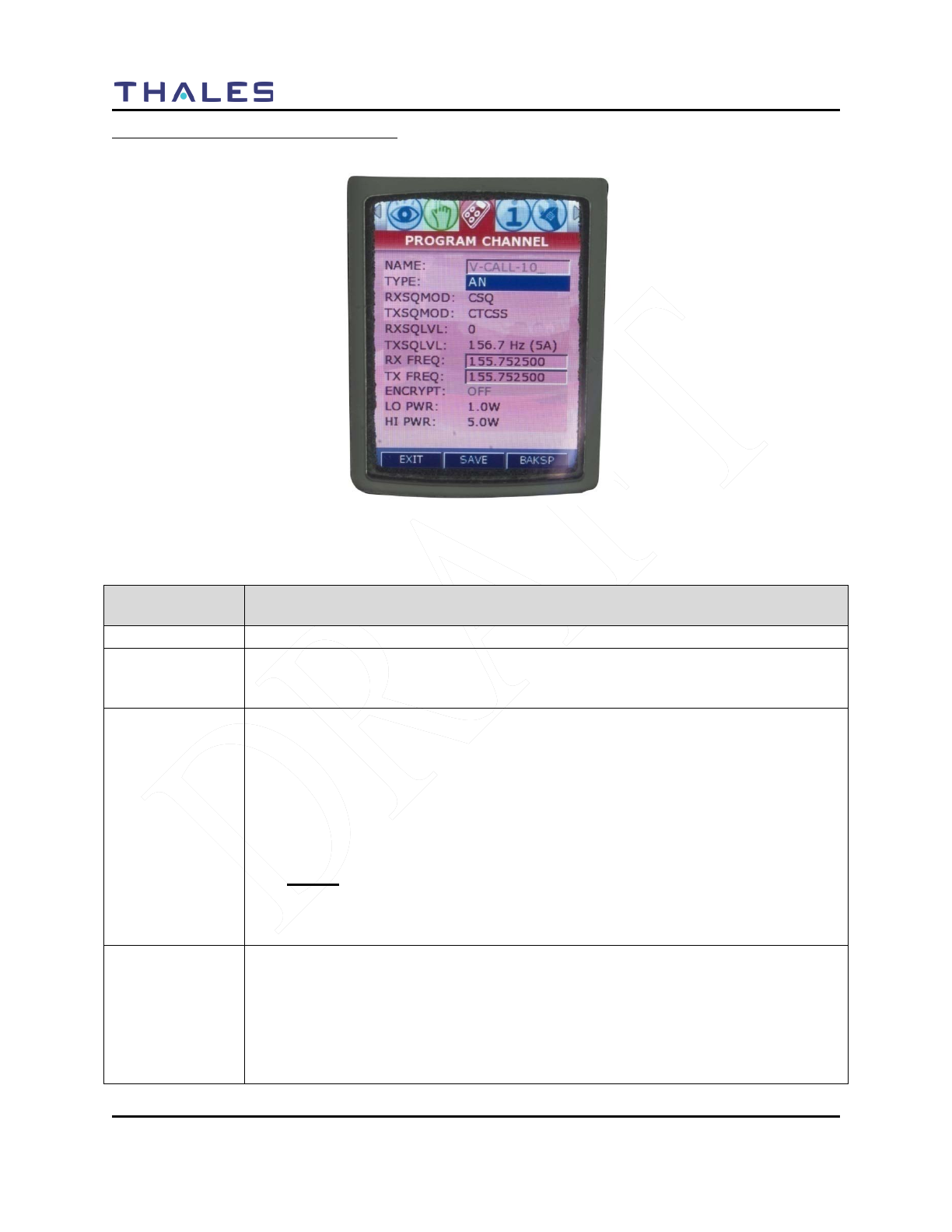
Channel Type – Analog Narrowband (AN)
Figure 2-9 PROGRAM Menu Screen – Analog Narrowband (AN)
Table 2-8 PROGRAM Menu – Analog Narrowband (AN)
Channel
Parameters
Description
NAME
Displays the Channel and Channel name.
TYPE
This selection provides the user with the ability to select the waveform type. When
TYPE is selected and ENT is pressed, a drop down list will appear with P25/ AN /
AW as the available options.
RX SQ MODE
RX SQ MODE is used to set the receive squelch mode and level. For Analog mode,
the desired receive CTCSS or CDCSS value, as appropriate, is entered in an entry
box, while the squelch NOISE level contains a drop down selection list with ranges
of 0-16, with 0 being open squelch.
When the radio is set for AN, the available selections are as follows:
RX SQ MODE is selected and ENT is pressed, a drop down list with the Analog
selections.
Analog
CSQ
CTCSS Tone (Refer to Table 3-7)
CDCSS Code (Refer to Table 3-8)
TX SQ MODE
TX SQ MODE is used to set the transmit squelch mode and level. For Analog
mode, the desired receive CTCSS or CDCSS value, as appropriate, is entered in an
entry box, while the squelch NOISE level while the squelch NOISE level contains a
drop down selection list with ranges of 0-16, with 0 being open squelch.
When the radio is set for AN, the available selections are as follows:
TX SQ MODE is selected and ENT is pressed, a drop down list with the either

DISPLAY / MENU SCREENS
Doc No. 84382 Rev 2
THALES COMMUNICATIONS, INC. PROPRIETARY INFORMATION 2-13
Channel
Parameters
Description
Analog selections.
Analog
OFF
CTCSS Tone (Refer to Table 2-10)
CDCSS Code (Refer to Table 2-11)
RXSQLVL
This selection allows the user to enter the desired receive squelch level. The available
options are 0-16, with 0 being open squelch.
TXSQLVL
This selection allows the user to enter the desired transmit squelch level when
CTCSS or CDCSS squelch mode is selected.
Rx FREQ
This selection allows the user to enter the Receive Frequency in MHz as:
XXX.XXXXX
For RX FREQ, the radio checks the frequency entered versus the band limits, (UHF,
VHF, 700 MHz, 800 MHz). The four band limits are as follows:
• VHF: 136–174 MHz
• UHF: 380–520 MHz
• 700 MHz: 763–775 MHz
•
800 MHz: 806–824/851–869 MHz
TX FREQ
This selection allows the user to enter the Transmit Frequency in MHz as:
XXX.XXXXX
For TX FREQ, the radio checks the frequency entered versus the band limits, (UHF,
VHF, 700 MHz, 800 MHz). The four band limits are as follows:
• VHF: 136–174 MHz
• UHF: 380–520 MHz
• 700 MHz: 763–775 MHz/793–805 MHz
• 800 MHz: 806–824/851–869 MHz
For the 700 MHz and 800 MHz bands, the radio also checks the frequency
separation of TX and RX for valid values; i.e., for the 700 MHz band, the separation
is 30 MHz with Receive the lower RF, while for the 800 MHz band, the separation is
45 MHz with Receive the higher RF. (In the 700/800 bands, the radio can
automatically set the second frequency once the first frequency, (typically RX), is
entered.) Also, since frequency is in steps of 3.125 and 2.5 kHz only, the radio
rounds each entered frequency to the nearest acceptable value
ENCRYPT
Not enabled this release.
LO TX PWR
This selection allows the user to set the low transmit power setting to any of the
values in the following table with default values in bold underlined type:
(VHF) (UHF) (700) (800)
0.1 0.1 0.1 0.1
0.5 0.5 0.5 0.5
1.0 1.0 1.0 1.0
2.0 2.0 2.0 2.0
3.0 3.0 2.5 3.0
4.0 4.0
DISPLAY / MENU SCREENS
2-14 Doc No. 84382 Rev 2
THALES COMMUNICATIONS, INC. PROPRIETARY INFORMATION
Channel
Parameters
Description
5.0 5.0
HI TX PWR
This selection allows the user to set the low transmit power setting to any of the
values in the following table with default values in bold underlined type:
(VHF) (UHF) (700) (800)
0.1 0.1 0.1 0.1
0.5 0.5 0.5 0.5
1.0 1.0 1.0 1.0
2.0 2.0 2.0 2.0
3.0 3.0 2.5 3.0
4.0 4.0
5.0 5.0
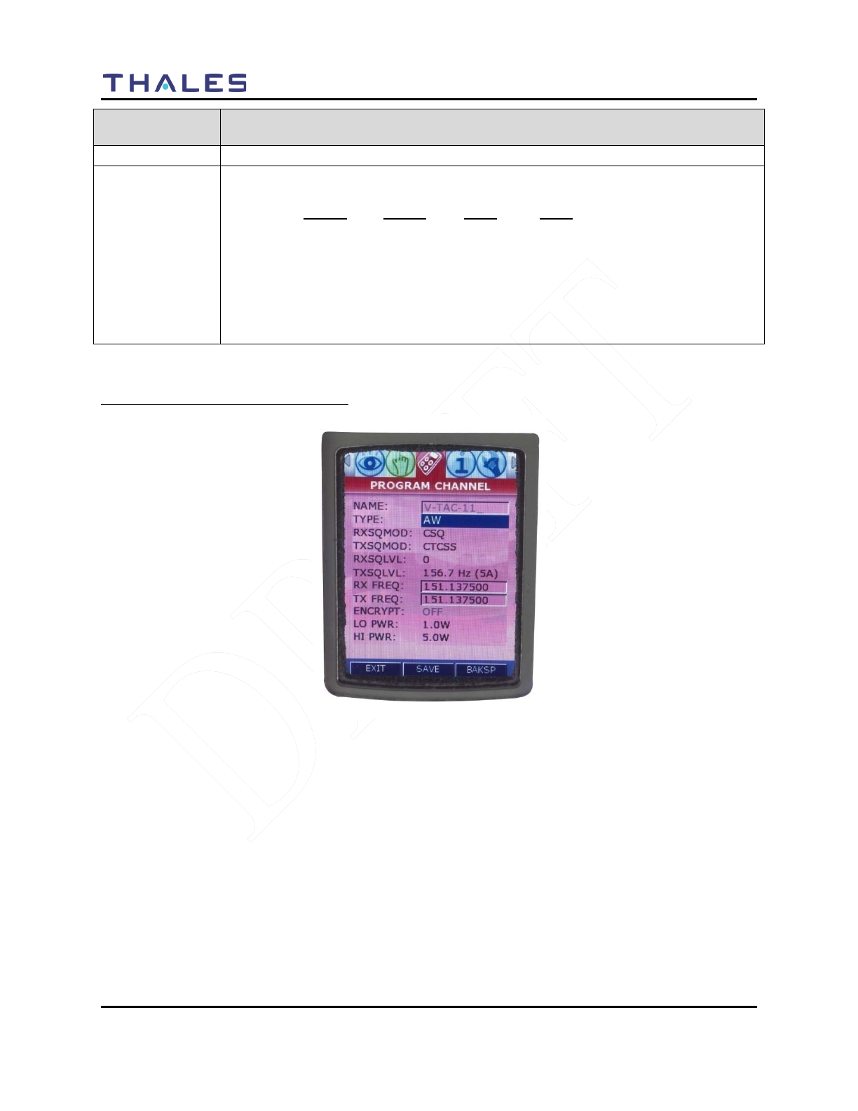
Channel Type – Analog Wideband (AW)
Figure 2-10 PROGRAM Menu Screen – Analog WideBand (AW)

DISPLAY / MENU SCREENS
Doc No. 84382 Rev 2
THALES COMMUNICATIONS, INC. PROPRIETARY INFORMATION 2-15
Table 2-9 PROGRAM Menu – Analog Wideband (AW)
Channel
Parameters
Description
NAME
Displays the Channel and Channel name.
TYPE
This selection provides the user with the ability to select the waveform type. When
TYPE is selected and ENT is pressed, a drop down list will appear with P25/ AN /
AW as the available options.
RX SQ MODE
RX SQ MODE is used to set the receive squelch mode and level. For Analog mode,
the desired receive CTCSS or CDCSS value, as appropriate, is entered in an entry
box, while the squelch NOISE level while the squelch NOISE level contains a drop
down selection list with ranges of 0-16, with 0 being open squelch.
When the radio is set for AN, the available selections are as follows:
RX SQ MODE is selected and ENT is pressed, a drop down list with the Analog
selections.
Analog
CSQ
CTCSS Tone (Refer to Table 3-7)
CDCSS Code (Refer to Table 3-8)
TX SQ MODE
TX SQ MODE is used to set the transmit squelch mode and level. For Analog
mode, the desired receive CTCSS or CDCSS value, as appropriate, is entered in an
entry box, while the squelch NOISE level while the squelch NOISE level contains a
drop down selection list with ranges of 0-16, with 0 being open squelch.
When the radio is set for AN, the available selections are as follows:
TX SQ MODE is selected and ENT is pressed, a drop down list with the either
Analog selections.
Analog
OFF
CTCSS Tone (Refer to Table 2-10)
CDCSS Code (Refer to Table 2-11)
RXSQLVL
This selection allows the user to enter the desired receive squelch level. The available
options are 0-16, with 0 being open squelch.
TXSQLVL
This selection allows the user to enter the desired transmit squelch level when
CTCSS or CDCSS squelch mode is selected.
Rx FREQ
This selection allows the user to enter the Receive Frequency in MHz as:
XXX.XXXXX
For RX FREQ, the radio checks the frequency entered versus the band limits, (UHF,
VHF, 700 MHz, 800 MHz). The four band limits are as follows:
• VHF: 136–174 MHz
• UHF: 380–520 MHz
• 700 MHz: 763–775 MHz
•
800 MHz: 851–869 MHz
TX FREQ
This selection allows the user to enter the Transmit Frequency in MHz as:
XXX.XXXXX
For TX FREQ, the radio checks the frequency entered versus the band limits, (UHF,
DISPLAY / MENU SCREENS
2-16 Doc No. 84382 Rev 2
THALES COMMUNICATIONS, INC. PROPRIETARY INFORMATION
Channel
Parameters
Description
VHF, 700 MHz, 800 MHz). The four band limits are as follows:
• VHF: 136–174 MHz
• UHF: 380–520 MHz
• 700 MHz: 763–775 MHz/793–805 MHz
• 800 MHz: 806–824/851–869 MHz
For the 700 MHz and 800 MHz bands, the radio also checks the frequency
separation of TX and RX for valid values; i.e., for the 700 MHz band, the separation
is 30 MHz with Receive the lower RF, while for the 800 MHz band, the separation is
45 MHz with Receive the higher RF. (In the 700/800 bands, the radio can
automatically set the second frequency once the first frequency, (typically RX), is
entered.) Also, since frequency is in steps of 3.125 and 2.5 kHz only, the radio
rounds each entered frequency to the nearest acceptable value
ENCRYPT
Not enabled this release.
LO TX PWR
This selection allows the user to set the low transmit power setting to any of the
values in the following table with default values in bold underlined type:
(VHF) (UHF) (700) (800)
0.1 0.1 0.1 0.1
0.5 0.5 0.5 0.5
1.0 1.0 1.0 1.0
2.0 2.0 2.0 2.0
3.0 3.0 2.5 3.0
4.0 4.0
5.0 5.0
HI TX PWR
This selection allows the user to set the low transmit power setting to any of the
values in the following table with default values in bold underlined type:
(VHF) (UHF) (700) (800)
0.1 0.1 0.1 0.1
0.5 0.5 0.5 0.5
1.0 1.0 1.0 1.0
2.0 2.0 2.0 2.0
3.0 3.0 2.5 3.0
4.0 4.0
5.0 5.0

DISPLAY / MENU SCREENS
Doc No. 84382 Rev 2
THALES COMMUNICATIONS, INC. PROPRIETARY INFORMATION 2-17
If CTCSS is chosen, a drop down list will be made available that contains the 42 valid CTCSS tones and
codes as listed in Table 2-10. The CTCSS tones are either provided as the actual audio tone (i.e. 127.3
Hz) or the Code (i.e. 3A). The drop down list provides both – select the required tone. The default value
is 67.0 Hz (XZ) (in bold).
Table 2-10 CTCSS Tones and Codes
67.0 Hz (XZ)
97.4 Hz (ZB)
141.3 Hz (4A)
203.5 Hz (M1)
69.3 Hz (WZ)
100.0 Hz (1Z)
146.2 Hz (4B)
206.5 Hz (8Z)
71.9 Hz (XA)
103.5 Hz (1A)
151.4 Hz (5Z)
210.7 Hz (M2)
74.4 Hz (WA)
107.2 Hz (1B)
156.7 Hz (5A)
218.1 Hz (M3)
77.0 Hz (XB)
110.9 Hz (2Z)
162.2 Hz (5B)
225.7 Hz (M4)
79.7 Hz (WB)
114.8 Hz (2A)
167.9 Hz (6Z)
229.1 Hz (9Z)
82.5 Hz (YZ)
118.8 Hz (2B)
173.8 Hz (6A)
233.6 Hz (M5)
85.4 Hz (YA)
123.0 Hz (3Z)
179.9 Hz (6B)
241.8 Hz (M6)
88.5 Hz (YB)
127.3 Hz (3A)
186.2 Hz (7Z)
250.3 Hz (M7)
91.5 Hz (2Z)
131.8 Hz (3B)
192.8 Hz (7A)
254.8 Hz (07)
94.8 Hz (2A)
136.5 Hz (4Z)
If CDCSS is chosen, a drop down list will be made available that contains the 83 valid CDCSS codes as
listed in Table 2-11. The default value is 023 (in bold).
Table 2-11 CDCSS Codes
023
114
174
315
445
631
025
115
205
331
464
632
026
116
223
343
465
654
031
125
226
346
466
662
032
131
243
351
503
664
043
132
244
364
506
703
047
134
245
365
516
712
051
143
251
371
532
723
054
152
261
411
546
731
065
155
263
412
565
732
071
156
265
413
606
734
072
162
271
423
612
743
073
165
306
431
624
754
074
172
311
432
627
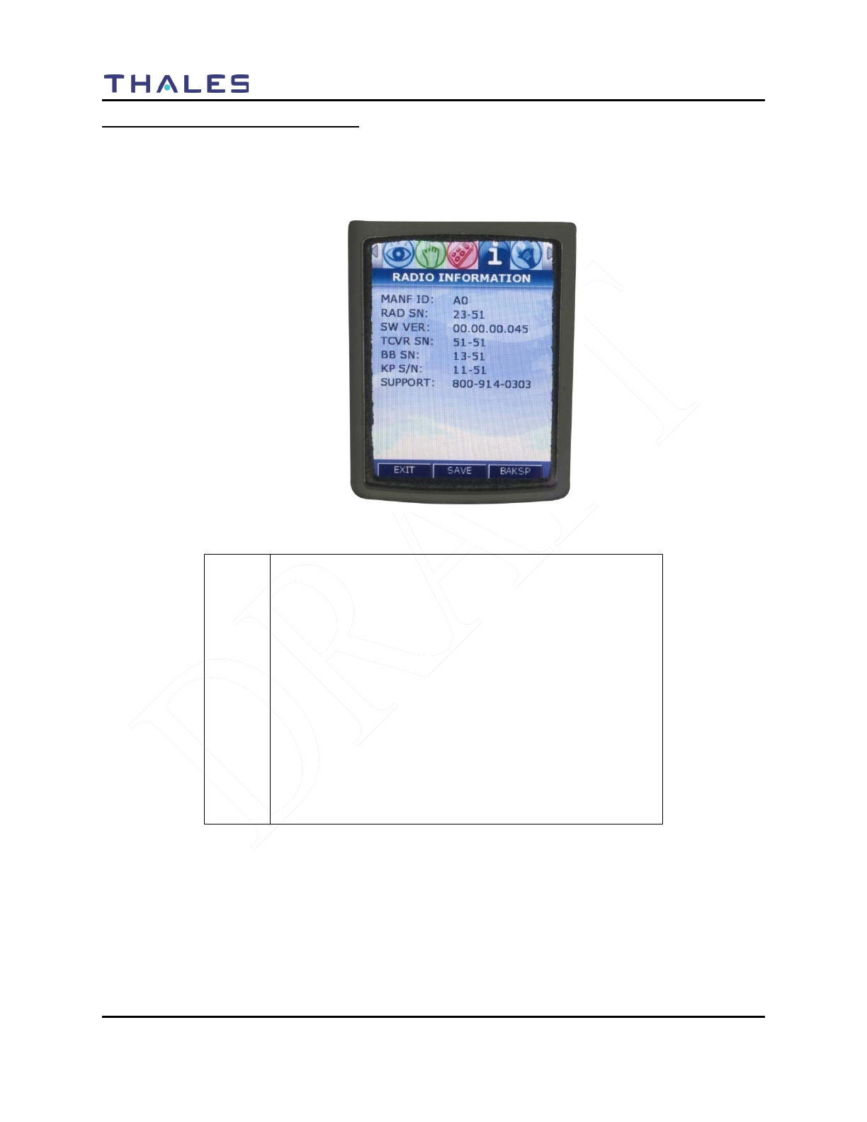
DISPLAY / MENU SCREENS
2-18 Doc No. 84382 Rev 2
THALES COMMUNICATIONS, INC. PROPRIETARY INFORMATION
RADIO INFORMATION Menu Screen
When highlighted on the Menu Screen, the RADIO INFORMATION Menu Screen is displayed as a
window select list as shown in Figure 2-11. This screen is for information only. The user cannot change
any parameter, including the enabled options on this screen.
Figure 2-11 RADIO INFORMATION Menu Screen
!
NOTE
Please use the following support contacts:
Bob DiDonato,
Thales Communications, Inc.
Mobile: 1-410-908-7678
Email: Bob.DiDonato@thalescomminc.com
Scott Glazer,
Thales Communications, Inc.
Mobile: 1-240-422-2612
Email: scott.glazer@thalescomminc.com
For support on any other Thales Equipment, please call
1-800-914-0303.
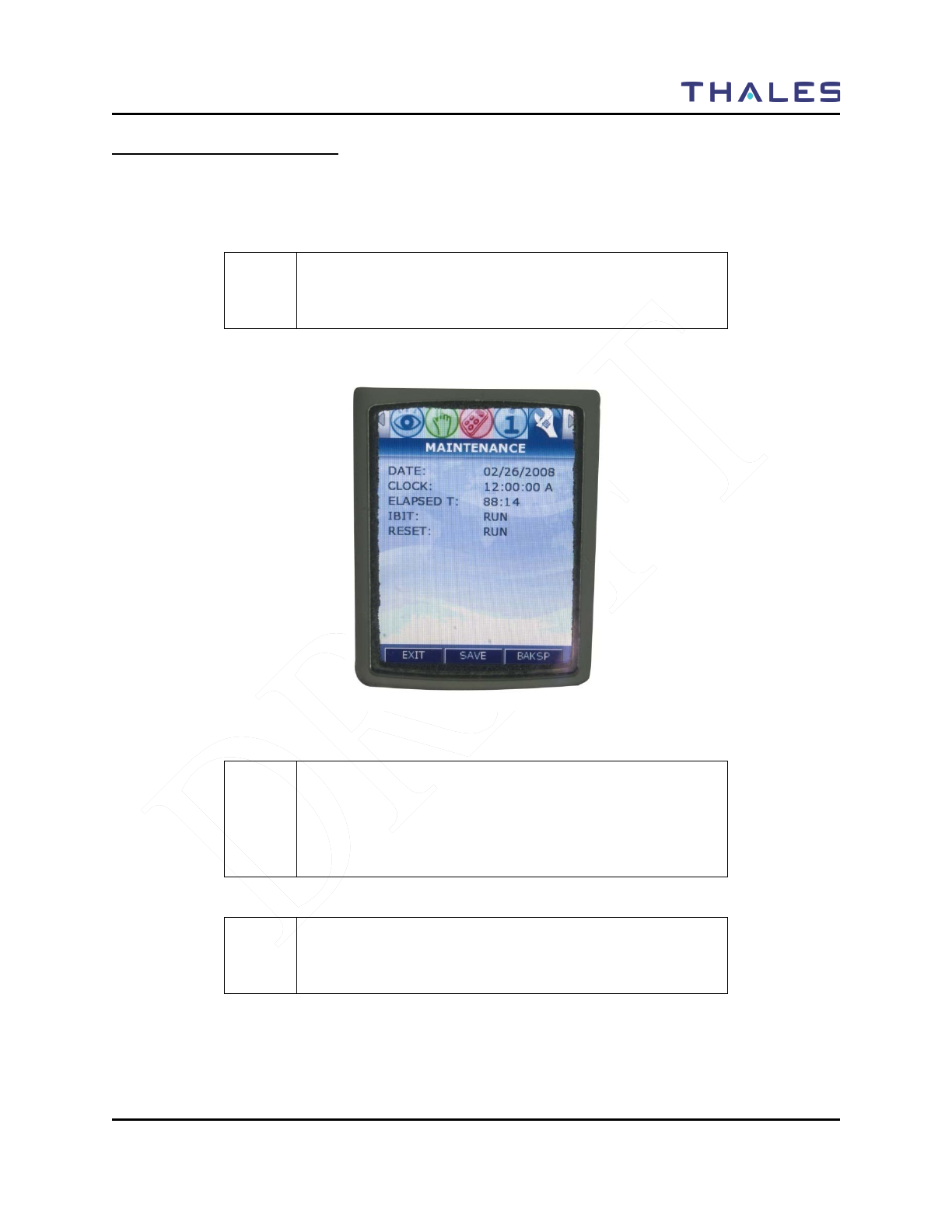
DISPLAY / MENU SCREENS
Doc No. 84382 Rev 2
THALES COMMUNICATIONS, INC. PROPRIETARY INFORMATION 2-19
MAINTENANCE Menu Screen
When highlighted on the Menu Screen, the MAINTENANCE Menu Screen is displayed as a window
select list as shown in Figure 2-12. The Up/Down Navigation Keys are used to scroll through the
available selections.
! NOTE
For additional information relating to Maintenance, refer to
Chapter 4 of this manual.
Figure 2-12 MAINTENANCE Menu Screen
! NOTE
This screen is temporarily being used for Downloading
Radio configuration file to radio (puts radio in program
mode by being on this screen) – for future releases of the
radio – this will be automatic.
! NOTE
The radio does not transmit or received while on the
Maintenance Screen.

DISPLAY / MENU SCREENS
2-20 Doc No. 84382 Rev 2
THALES COMMUNICATIONS, INC. PROPRIETARY INFORMATION
Table 2-12 MAINTENANCE Menu Options
Channel
Parameters
Description of Function
DATE
This selection displays the date in mm/dd/yyyy.
CLOCK
This selection displays the time in hours:minutes:seconds:tenths of seconds. A
Global Setting determine whether a 24 hour or a 12 hour (with AM or PM) time is
displayed.
ELAPSED TIME
This selection displays the total time the radio has been in Transmit mode (PTT
pressed), Receive mode (actively receiving radio signals with audio output), and
Standby mode (powered on but neither transmitting nor receiving). The time is
shown in hours:minutes.
IBIT
FUTURE -- The IBIT (Initiated Built-In-Test) function runs self-test of the primary
radio boards and functions. If there is a failure, the screen will show the test results
(PASS or FAIL) for each test.
RESET
FUTURE -- The RESET function provides a means for the user to “reset” the radio
by initiating a “Warm Boot” of the radio. A “Warm Boot” is a restart of the radio by
resetting the radio configuration parameters and executing POST, but not performing
a battery authentication or powering down the radio. Selecting “OK” and pressing
ENT resets the radio by initiating the “Warm Boot”.

OPERATING INSTRUCTIONS
Doc No. 84382 Rev 2
THALES COMMUNICATIONS, INC. PROPRIETARY INFORMATION 3-1
CHAPTER 3 OPERATING INSTRUCTIONS
GENERAL INFORMATION
This section describes the operating procedure for the radio. This chapter contains the following:
Description
Page Number
General Information
3-1
Operating Instructions
3-1
Connecting the Battery
3-1
Connecting the Antenna
3-1
Radio Programming
3-1
Turning on the Radio
3-2
Menu Access
3-3
Transmitting
3-4
Receiving
3-4
P25 Unit to Unit Call
3-5
SCAN – Conventional and Priority
3-5
Using the Programmable Side Buttons
3-8
Squelch Monitor
3-8
Hi/Low Power
3-8
Talk Around
3-8
Modifying Menu Selections – SELECT Menu or
PROGRAM Menu
3-9
Changing ZONES
3-9
Screen Saver
3-10
OPERATING INSTRUCTIONS
Connecting the Battery
The battery is connected to the radio by inserting the top of the battery under the flap at the top of the
radio and snap down into place.
Connecting the Antenna
The antenna is connected to the radio through a connector on top of the radio. Screw the antenna
clockwise onto the connector until it is fully seated.
Radio Programming
Prior to operation for the first time, the radio should be programmed via the PC Programmer. For help in
programming a radio using the PC Programmer see the MA6941U PC Programmer's User Manual, Thales
part number 84404.
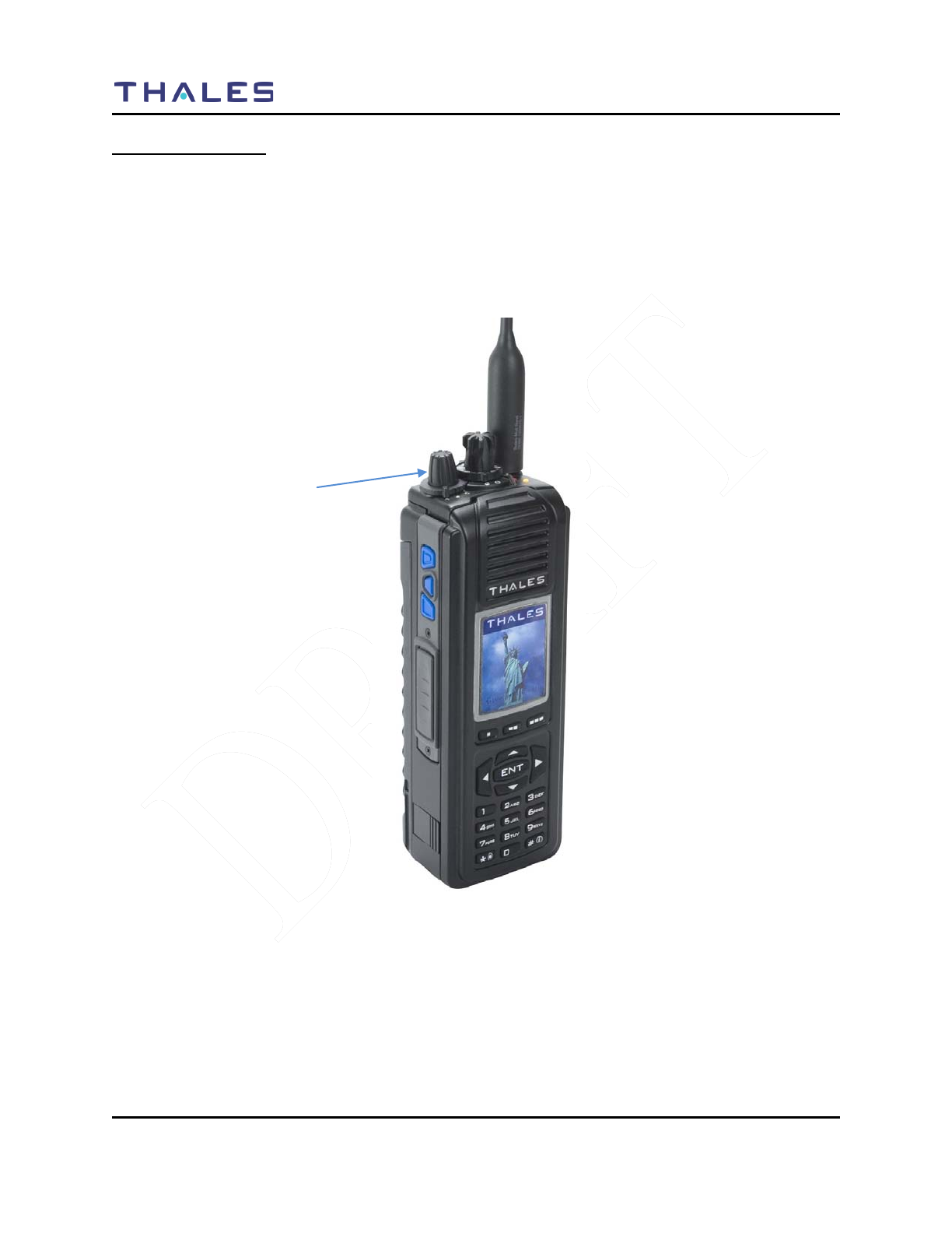
OPERATING INSTRUCTIONS
3-2 Doc No. 84382 Rev 2
THALES COMMUNICATIONS, INC. PROPRIETARY INFORMATION
Turning on the Radio
Turn on the radio using the On/Off/Volume knob. The radio will go through a boot-up sequence,
displaying a blank screen, the Thales Screen, the Liberty Screen and an Operating Screen.
The radio has a Power-On-Self-Test (POST) function that checks basic radio functions every time the
radio is powered up.
Use the switch to set the volume to a comfortable level. Select the desired channel using the Channel
Select Switch. The radio is now ready for operation.
Figure 3-1 Radio ON/OFF/Volume Knob and ZONE Select
ON/OFF/Volume,
ZONE Select
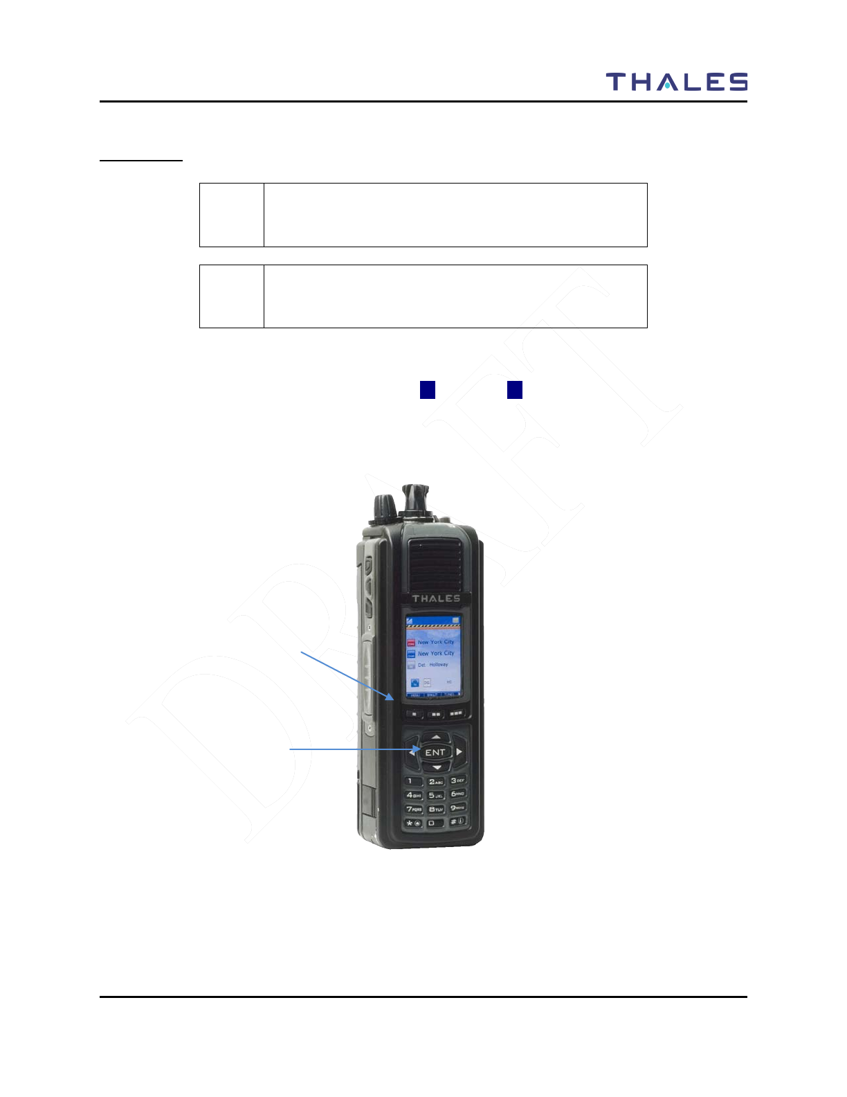
OPERATING INSTRUCTIONS
Doc No. 84382 Rev 2
THALES COMMUNICATIONS, INC. PROPRIETARY INFORMATION 3-3
Menu Access
! NOTE
Refer to Chapter 1 for additional information relating to the
navigation keys.
! NOTE
When the HOME Screen is displayed, the ENT button
functions as a “hotkey” short-cut to the MENU Screen.
• Press the MENU softkey or the ENT button to access menus
• Once in the MENU’s, the user uses the left (◄) and right (►) arrows allows navigation between
each screens, by paging left or right to the applicable Menu.
• Press EXIT to return to the HOME Screen.
Figure 3-2 Menu Access
MENU Softkey
NAV ENTER
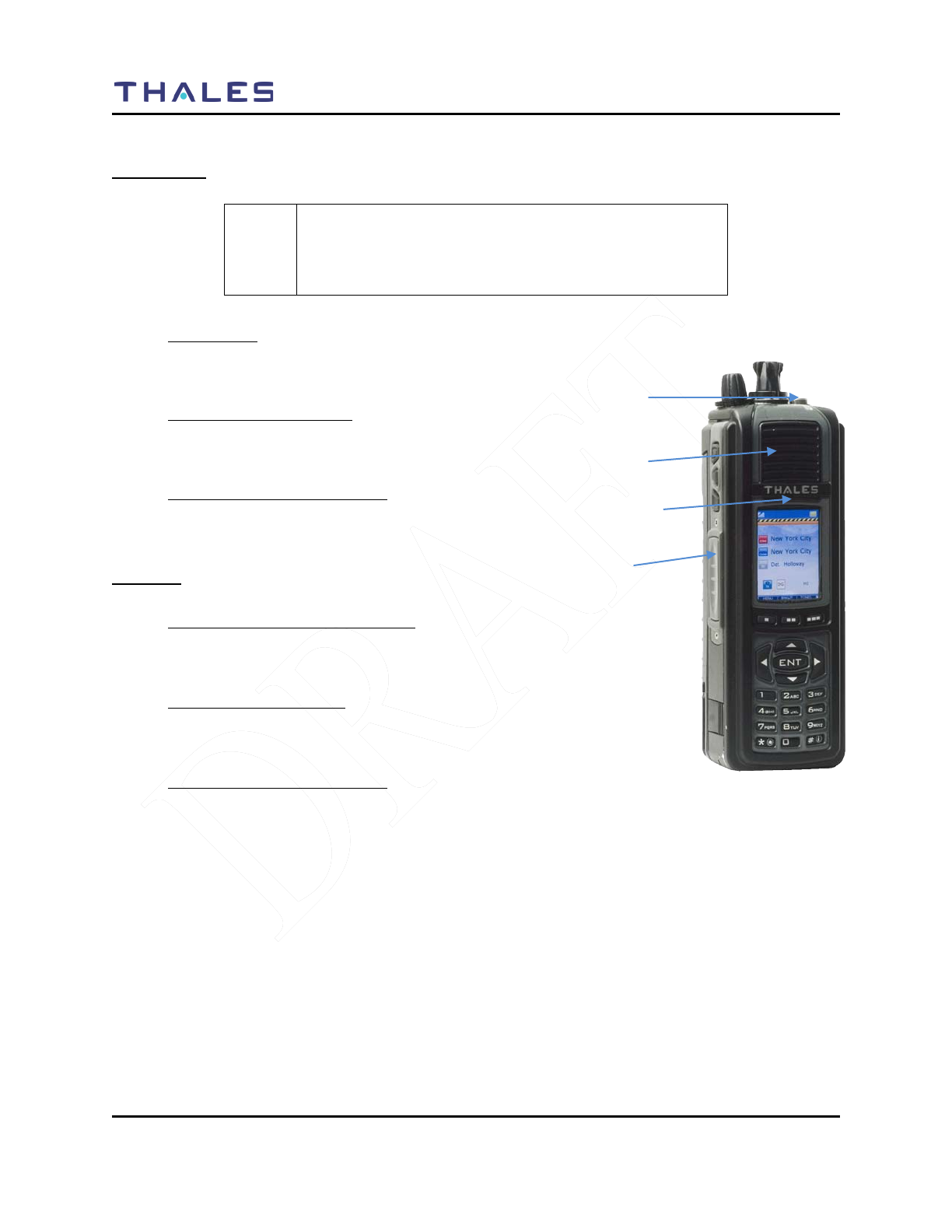
OPERATING INSTRUCTIONS
3-4 Doc No. 84382 Rev 2
THALES COMMUNICATIONS, INC. PROPRIETARY INFORMATION
Transmitting
! NOTE
Prior to transmitting, verify that the LED is NOT lit Green
(solid or flashing) as this indicates RF traffic on that
channel. Wait for it to clear.
• To Transmit:
– Push the PTT button
– Speak into microphone (3-6 inches away)
• LED Transmit Indications:
– OFF – Not Transmitting or Receiving
– RED - Transmitting
• Transmitting with Speaker/Mic:
– Push PTT on Speaker/Mic
– Speak into Speaker/Mic
Receiving
• Conventional Channels Talkgroups:
– Verify PTT is NOT pressed
– Audio will come through the Speaker or Speaker/Mic.
• LED Receive Indications:
– OFF – Not Transmitting or Receiving
– GREEN – Receiving Signal
• Transmitting with Speaker/Mic:
– Push PTT on Speaker/Mic
– Speak into Speaker/Mic
LED
MIC
PTT
Speaker
Figure 3-3 Radio ON/OFF/Volume Knob
and ZONE Select
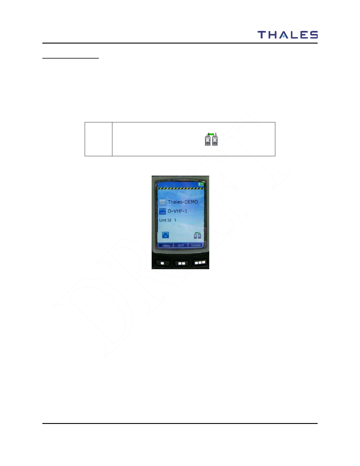
OPERATING INSTRUCTIONS
Doc No. 84382 Rev 2
THALES COMMUNICATIONS, INC. PROPRIETARY INFORMATION 3-5
P25 Unit to Unit Call
To place a call within your unit,
1. Press the PRIV Softkey from the HOME screen.
2. Enter the Unit ID number.
3. Press enter, then press PTT to initial the call. The Unit ID will be active until a different channel
is selected, or the user presses EXIT.
! NOTE
The Individual Call or Page icon ( ) will appear on the
Operating Screen.
Figure 3-4 P25 Unit to Unit Call

OPERATING INSTRUCTIONS
3-6 Doc No. 84382 Rev 2
THALES COMMUNICATIONS, INC. PROPRIETARY INFORMATION
Scanning – Conventional and Priority
! NOTE
Selection of Channels for scanning is preprogrammed
through the PcP. Up to 16 channels can be scanned at a
time.
! NOTE
Scanning can be performed by pressing one of the pre-
programmed side buttons.
Enable SCAN
1. Press one of the side buttons that has been pre-programmed to SCAN.
! NOTE
A scan bar on the main screen will provided indication that
the radio is scanning the channels in the SCANLIST.
! NOTE
If the SCAN list is empty or there is no scan list, the user
will not be able to select SCAN ON.
Priority Scan
To enable priority scan, press the pre-programmed side button. When the radio is in Priority Scan, the
main screen will show the scan bar, plus any of the following:
• “P1” if no priority channels are defined (current channel will become P1)
• “P1” if only P1 was defined or only P2 was defined (1 priority channel)
• “P2” if P1 and P2 were both defined.
The radio will continue to scan using the P1/P2 priority channels, alternating between P1 and P2.
1. If one of the side button has been enabled for Priority Scan , press the side button to enable
Priority Scan.
! NOTE
If SCAN is not ON, than pressing the programmed “Priority
Scan” button just sets the mode to priority scanning.
Scanning does not actually turn on until SCAN is set ON.

OPERATING INSTRUCTIONS
Doc No. 84382 Rev 2
THALES COMMUNICATIONS, INC. PROPRIETARY INFORMATION 3-7
! NOTE
If no priority channels are defined the radio includes the
current channel as the priority (P1) channel.
Table 3-1 Scan and Priority Scan Side Button Options
Side Buttons
Comment
PSCAN->SCAN
Priority scanning is alternately enabled/disabled on PSCAN
press.
SCAN->PSCAN-SCAN
When priority scanning is running and the SCAN side button is
pressed the radio will stop scanning. The next SCAN button
press will resume priority scanning (priority scanning persists
until power down)
Receiving a Voice Call on a Channel in the Scan List
If a voice call is received on a channel that is in the scan list, the radio will break squelch on the channel
when the call is received. The main screen will “temporarily change to the scan Rx channel, indicating
which ZONE, SCAN Channel, frequency, and ID information.
! NOTE
When a call is received, the scan function will stop. And
when the call has ended, the radio will resume scanning.
Monitor Timer
The Monitor Timer is the amount of time the radio will sample a channel picked up during a scan before
the radio returns to scan operation. At the end of the monitor period, the radio will break reception and
continue with the scan sequence. If the signal is still there during the next scan cycle, it will be picked up
again. The Monitor Timer is pre-programmed by the PcP.
SCAN Hold Timer
If Talkback is disabled, the Scan Hold Timer allows a user to monitor a channel that was picked up while
scanning prior to re-entering the scan sequence. In addition, if Talkback is disabled, the Talkback Scan
Timer is not used. This is required to hear both sides of a conversation for example.
OPERATING INSTRUCTIONS
3-8 Doc No. 84382 Rev 2
THALES COMMUNICATIONS, INC. PROPRIETARY INFORMATION
Using the Pre-Programmed Side Buttons
The side buttons have been pre-programmed using the PcP. The following information provides a quick
summary on how to use each of the buttons.
! NOTE
The following information assumes that the side buttons
have been pre-programmed using the PcProgrammer.
Currently the side buttons can be programmed for HI/Low
Power; Monitor, Scan, Priority Scan, and Talk-Around
Squelch Monitor Side Button
1. Select an analog channel that has a RX squelch setting of anything other than “0”.
2. Press the Monitor side button.
3. The radio will immediately breaks squelch on the current channel. The channel will remain
“open squelch” indefinitely in this mode.
4. To stop monitoring on this channel, press the monitor side button.
5. The radio reverts to its current squelch mode setting. If squelch signal is present on the channel
the radio will remain open squelch, otherwise it will close squelch.
If a channel or Zone is changed with Monitor Enabled:
1. If a channel or zone is changed on the radio, the radio will immediately open squelch on the new
channel (monitor mode remains on).
2. Once the Monitor side button is pressed, the radio will close squelch.
3. The user may change back to the original channel.
4. The original channel is operating with normal squelch settings.
HI/LO Power Side Button
The Hi/Low Power Side Button provides the user with the capability to switch power setting on any given
channel. The main menu will either display a HI or LO icon ( or ) depending on the particular
channel power settings.
Talk Around
! NOTE
The following information assumes that the channel has
Talk-Around option has been enabled and that one of the
side buttons has been pre-programmed by the
PcProgrammer.
1. The user selects a channel that has been programmed for Talk Around.
2. Press the Talk Around side button. When the radio is in Talk-Around, the main screen will
display the TA icon ( ).
3. The radio transmits and receives on the same frequency.
HI
LO

OPERATING INSTRUCTIONS
Doc No. 84382 Rev 2
THALES COMMUNICATIONS, INC. PROPRIETARY INFORMATION 3-9
Modifying Menu Selections – SELECT Menu or PROGRAM Menu
! NOTE
Unless otherwise noted, the following “hints” apply to each
menu:
• If an entry is grayed out – it cannot be changed by the
user.
• If a drop down menu appears after ENT is pressed, the
user may select from this drop-down menu.
• If no drop down screen appears, the user may use the
numeric keypad to enter the required information, such as
frequency range, RX/TX NAC, RX/TX TG using the
numeric keypad.
1) Press the MENU Softkey or press ENT from the HOME screen to enter the menus.
2) Using the left / right arrow keys scroll to the applicable menu.
3) To edit an entry in that menu, press either the up () or down () arrows to scroll to desired line
item. The user may either select from drop-down menus or enter data directly using the numeric
keypad.
4) After the changes have been completed, hit the SAVE softkey.
5) To move to the next menu, press the up arrow until you reach the top of the menu, then use the
left (◄) and right (►) arrows to move to the next menu.
! NOTE
If you click EXIT after you have save your changes, you
will be returned to the HOME Screen.
Changing ZONES
The first three (3) zones can be selected by the 3-position switch (FIXED at Zone Select for Initial
Release) (Refer to Figure 3-1). Additional zones can be accessed by going to SELECT Menu (as
described in Chapter 2).

OPERATING INSTRUCTIONS
3-10 Doc No. 84382 Rev 2
THALES COMMUNICATIONS, INC. PROPRIETARY INFORMATION
Screensaver
The Liberty ™ Radio is equipped with a screensaver that turns the color display OFF after a period of
inactivity (similar to cell-phones) to conserve battery life.
The color screen can be re-activated by any of the following actions:
• Received call
• Press PTT
• Change volume or channel
• Press any key
! NOTE
The ENTER Light stays ON, but maybe difficult to see in
bright light.
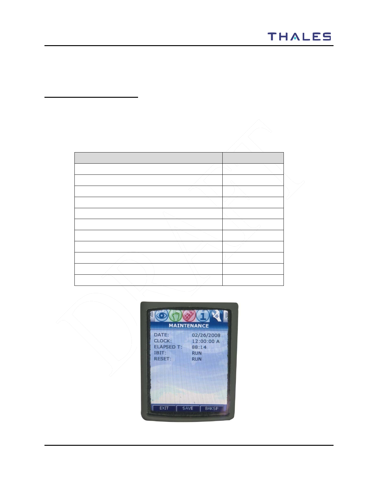
MAINTENANCE
Doc No. 84382 Rev 2
THALES COMMUNICATIONS, INC. PROPRIETARY INFORMATION 4-1
CHAPTER 4 MAINTENANCE
GENERAL INFORMATION
This chapter provides operator maintenance instructions for the LibertyTM Radio. This includes
operational checkout, inspection and preventive maintenance, troubleshooting, and removal/replacement
procedures.
This chapter contains the following:
Description Page Number
General Information 4-1
Operational Checkout 4-2
Radio Preventative Maintenance 4-2
Inspection and Cleaning 4-2
External Battery Preventative Maintenance 4-2
Troubleshooting 4-3
Removal/Replacement Procedures - Operator 4-4
Audio Removal/Replacement 4-4
Antenna Removal/Replacement 4-4
Battery Removal/Replacement 4-5
Radio Disassembly 4-5
Figure 4-1 Maintenance Menu Screen

MAINTENANCE
4-2 Doc No. 84382 Rev 2
THALES COMMUNICATIONS, INC. PROPRIETARY INFORMATION
OPERATIONAL CHECKOUT
The LibertyTM radio provides three types of BIT:
• POST – Power On Self Test (POST) function that checks the basic radio functions every
time the radio is powered up.
• CBIT – Continuous Built In Test (CBIT); this series of radio self tests are run in the
background during normal operation
• IBIT – Initiated Built In Test (IBIT); this series of radio self tests are run when requested
by the user (FUTURE)
RADIO PREVENTIVE MAINTENANCE
Inspection and Cleaning
The radio should be occasionally inspected for external damage, such as bent connectors, and wear items,
such as loose attaching hardware (screws and setscrews). The radio should be cleaned periodically,
particularly after exposure to salt water, sand, or mud. The user should wipe exposed contacts, such as
the side connector, battery connector, and audio connector with fresh water and then dry with low
pressure air, if available. Small pieces of dirt and debris may infiltrate the grill of the internal speaker and
should be cleaned out with a soft brush or blown out with low pressure air (if available) to remove any
particles
EXTERNAL BATTERY PREVENTIVE MAINTENANCE
Lithium-ion batteries will self-discharge over time. If not periodically recharged, the voltage level can
get so low that the maximum potential capacity is reduced or the battery may not accept a recharge. In
order to prevent the effect of excessive self-discharge, it is recommended that lithium-ion batteries that
are not in regular use (e.g., in storage) be regularly recharged to full capacity. However, the LibertyTM
Battery has an 18 month shelf life. In ideal situations, it is recommended that the battery be stored at room
temperature and low humidity.

MAINTENANCE
Doc No. 84382 Rev 2
THALES COMMUNICATIONS, INC. PROPRIETARY INFORMATION 4-3
TROUBLESHOOTING
There are only a limited number of equipment failures that can be corrected by the operator. The
following table describes them.
Table 4-1 Operator Troubleshooting Guide
Symptom Probable Cause Corrective Action
Radio does not operate • Battery not properly connected
• Before removing battery from the
radio, make sure the radio is turn-off
first.
• Remove and re-install battery – be
sure to clean the battery contacts
before re-installing the battery.
• Battery dead • Either Charge or Replace battery
Screen Blank • Radio in screen saver mode • To re-activate the screen – press
PTT, change the volume or channel,
or press any key. The screen will
also be re-activated when a call is
received.
Cannot communicate
with other radio users • Radios set to different
frequencies
• Set all radios to the same
frequency (can be accomplished by
loading from PC Programmer).
• Radios are set with different
CTCSS tones • Set receive and transmit CTCSS
tones the same in all radios
• Radios set to different
modulation types • Set radios to same modulation type
External
Speaker/Microphone not
working (no audio)
• External Speaker/Mic not
properly installed • Verify speaker / mic is attached
correctly.
• No audio
• Remove and replace the external
audio speaker/microphone.
• Check the INT/EXT Audio Switch
- Current Functionality –
EXT/INT Audio (“
”
EXT and
“0” INT)
Radio does not scan • SCANLISTS not programmed
into radio. • Set SCANLISTS in the PcP and
download to the radio.
Radio does not
communicate with
PcProgrammer
• PcProgrammer not installed
correctly. • Refer to PcProgrammer manual for
installation instructions of the
software.
• PcProgrammer Cable not
connected properly • Check cable connections, remove
and re-attach PcProgramming cable.

MAINTENANCE
4-4 Doc No. 84382 Rev 2
THALES COMMUNICATIONS, INC. PROPRIETARY INFORMATION
REMOVAL/REPLACEMENT PROCEDURES - OPERATOR
The first step for any remove/replace procedure is to power down the equipment. Prior to removing or
installing any LibertyTM assembly, remove all accessories (antenna, microphone, etc.).
Removal/replacement procedures that are authorized to be performed by the operator are given in the
following paragraphs.
CAUTION
Before performing removal/replacement procedures, make
sure the radio is powered down and the battery is removed
from the radio.
Audio Accessory Removal/Replacement .
Remove/replace the audio accessory as follows:
a. Disconnect the audio accessory (e.g., handset), from the audio accessory connector on the
side of the radio.
b. Replace the audio accessory with a known good one.
Antenna Removal/Replacement.
Remove/replace antenna as follows:
a. Disconnect the antenna from the antenna connector at the top of the radio by first grasping
the antenna at the base and turning counterclockwise until unthreaded. Then remove the
antenna from the connector.
b. Replace the antenna with a known good antenna. Turn antenna clockwise to thread it into
position. The antenna should be hand-tightened only.

MAINTENANCE
Doc No. 84382 Rev 2
THALES COMMUNICATIONS, INC. PROPRIETARY INFORMATION 4-5
Battery Removal/Replacement.
Remove/replace battery as follows:
WARNING:
The LibertyTM Li-ion Rechargeable Batteries are fully
recyclable and should be disposed of using an appropriate
system (such as a special recycling center or via your local
government waste disposal center.
Never throw your battery out with the household waste or
attempt to incinerate. Lithium Ion cells contain non-
biodegradable components, hazardous chemical and are
prone to aggressive explosion under intense heat.
CAUTION
Turn off power before removing the battery by setting the
volume switch to the OFF position. Failure to do so may
corrupt the programmed configuration and may damage the
radio circuitry.
a. To disconnect the battery from the radio, press the tabs on both sides to release and lift out
from battery.
b. To replace the battery, insert the top of the battery, under the flap at the top and click tabs in
place at the bottom of the radio.
RADIO DISASSEMBLY
The LibertyTM Radio is not authorized for disassembly. If the chassis is inadvertently opened, it MUST be
returned to Thales Communications Inc for inspection and repair.

MAINTENANCE
4-6 Doc No. 84382 Rev 2
THALES COMMUNICATIONS, INC. PROPRIETARY INFORMATION
THIS PAGE INTENTIONALLY LEFT BLANK
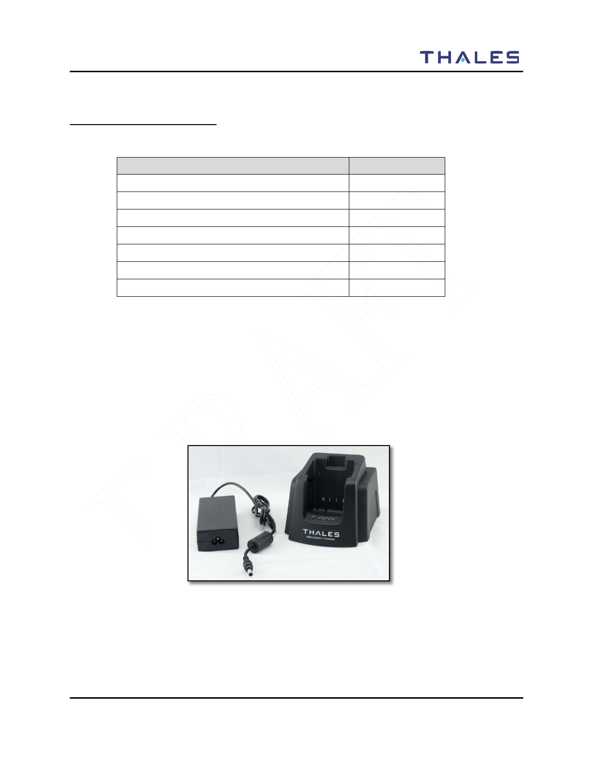
BATTERY CHARGERS
Doc No. 84382 Rev 2
THALES COMMUNICATIONS, INC. PROPRIETARY INFORMATION 5-1
CHAPTER 5 BATTERY CHARGERS
GENERAL INFORMATION
This chapter contains the following:
Description Page Number
General Information 5-1
Physical Characteristics 5-2
Weight and Dimensions 5-2
Temperature 5-2
Electrical Characteristics 5-2
Performance 5-2
Operating Indications 5-3
For the DHS Initial Pilot Field Trials, only the following chargers will be available:
• Standard Single-Bay Charger (PN 1600682-1)
The single unit charger (P/N 1600682-1) operates on 90 to 260 VAC power only. The battery charger
charges the battery to full charge within three hours, automatically adjusting to the appropriate settings when
the battery is inserted. The battery chargers communicate with the circuitry in the battery to monitor charge
current, temperature, and voltage to prevent improper charging. Indicator LED’s on the chargers provide
status.
Figure 5-1 LibertyTM Single-Bay Charger

BATTERY CHARGERS
5-2 Doc No. 84382 Rev 2
THALES COMMUNICATIONS, INC. PROPRIETARY INFORMATION
PHYSICAL CHARACTERISTICS
Weight and Dimensions
The charger weights and dimensions are shown below:
Table 5-2 Battery Charger Weights and Dimensions
Charger
Configuration Part
Number Weight (excluding power
cord or vehicle adapter) Size (excluding power
cord)
Standard Single Unit
Charger 1600682-1 < 2 pounds Approx. 5.0 inches (W) x 4.0
inches (H) x 4.0 inches (D).
Temperature
The chargers’ charging and storage temperature ranges are shown below:
Table 5-3 Charging and Storage Temperatures
Descriptions Temperature
Charging Temperature Range -10°C (+14°F) to +55°C (+131°F)
Storage (Non-operational) Temperature Range: -40°C (-40°F) to +85°C (+185°F)
Attempting to charge batteries outside the operating temperature range can result in damage to both the
chargers and batteries.
ELECTRICAL CHARACTERISTICS
Table 5-4 Charging and Storage Temperatures
Charger Type Electrical Characteristics
Single Unit Charger 90 to 264 VAC, 47-63 Hz
PERFORMANCE
Battery charge time can be affected by various conditions, such as the charger input current. When
inserting a battery, make sure it is firmly seated in the charger. The battery chargers communicate with the
circuitry in the battery to monitor charge current, temperature, and voltage to prevent improper charging.
Indicator LED’s on the chargers provide status.
Table 5-5 Charger Performance
Charger Configuration Capacity Charge Time
Single Bay AC One battery pack Three hours
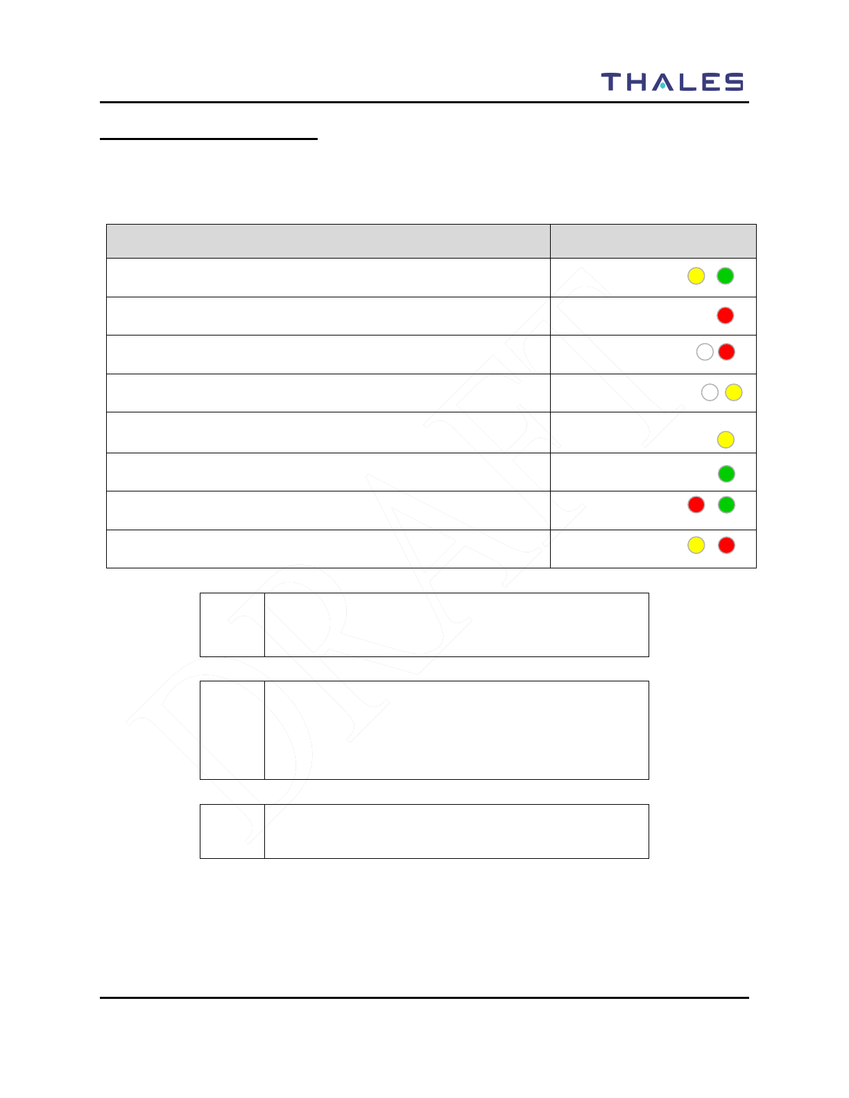
BATTERY CHARGERS
Doc No. 84382 Rev 2
THALES COMMUNICATIONS, INC. PROPRIETARY INFORMATION 5-3
OPERATING INDICATIONS
All versions of the chargers use LEDs to indicate the current charging status and/or charging problems.
The meanings of the LED’s are as follows:
Table 5-6 Single-Bay Charge Status Indicators
Description Indication
The charger will display a flashing yellow/green LED indication while it
attempts to establish communications with the battery. FLASHING
YELLOW/GREEN
If the battery temperature exceeds its maximum operating temperature the
charger shall set the status LED to solid RED
RED
If the battery status indicates an over-discharged condition, the charger shall
set the status LED to flashing RED
FLASHING RED
If the battery temperature is below 0°C, the charger shall set the status LED
to flashing YELLOW.
FLASHING YELLOW
During charging, the charger shall set the status LED to solid Yellow.
YELLOW
When charging is > 90%, the charger shall set the status LED to GREEN.
GREEN
When a battery/charger error is detected, the charger shall set the status LED
to flash RED/GREEN. FLASHING
RED/GREEN
When a Charger error condition is detected, the charger shall set the status
LED to flashing YELLOW/RED. FLASHING
YELLOW/RED
CAUTION
Do not insert a new battery in the charger until
the LED is turned off.
! NOTE
If a battery is inserted in the charger while attached to a
radio and the radio is ON, the radio fuel gauge may indicate
that the battery is fully charged before the charger indicates
full charge.
! NOTE
The battery can be charged while attached to a radio.

BATTERY CHARGERS
5-4 Doc No. 84382 Rev 2
THALES COMMUNICATIONS, INC. PROPRIETARY INFORMATION
THIS PAGE INTENTIONALLY LEFT BLANK
ACCESSORIES/ANCILLARY EQUIPMENT
Doc No. 84382 Rev 2
THALES COMMUNICATIONS, INC. PROPRIETARY INFORMATION 6-1
CHAPTER 6 ACCESSORIES AND ANCILLARY EQUIPMENT
GENERAL
This chapter provide information concerning the various accessories that can be used with the LibertyTM
Radio manufactured by Thales Communications, Inc., Clarksburg, Maryland.
This chapter contains the following:
Description Page Number
General 6-1
Available Ancillary Equipment for the LibertyTM
Radio 6-1
Antennas 6-1
Batteries 6-2
Battery Chargers 6-2
Cases / Holsters 6-3
Audio Accessories 6-3
Cables 6-4
Surveillance Equipment 6-4
AVAILABLE ACCESSORIES AND ANCILLARY EQUIPMENT FOR THE LIBERTYTM
RADIO
Antennas
One antenna is supplied for the LibertyTM Radio:
Table 6-1 Antenna Versions
Part Number Freq Band
1600678-1 136-174 MHz, 380-520 MHz, 763-869 MHz
The antenna is attached via a connector on the top of the radio. A protective screw-on cap is attached to the
connector at the base of each antenna to protect the connector from dirt and moisture when the antenna is
not attached to the radio.
ACCESSORIES/ANCILLARY EQUIPMENT
6-2 Doc No. 84382 Rev 2
THALES COMMUNICATIONS, INC. PROPRIETARY INFORMATION
Batteries
The following batteries are available for the LibertyTM Radio:
Table 6-2 LibertyTM Batteries
Part Number Description
1600691-1 3-Cell Sealed Rechargeable Lithium Ion Battery Pack, 2400 mAh
Capacity
1600691-2 6-Cell Sealed Rechargeable Lithium Ion Battery Pack, 4800 mAh
Capacity
4102201-501
(FUTURE)
AA Clamshell – Black, AA battery (12 AA Alkaline Cells) Clamshell
Cassette
4102201-502
(FUTURE)
AA Clamshell – Orange, AA battery (12 AA Alkaline Cells) Clamshell
Cassette
4102265-501
(FUTURE)
Battery Eliminator, powers the radio from external DC power source,
provides reverse polarity as well as over voltage and over-current
protection for the radio. Accepts nominal 12V DC input voltage.
Battery Chargers
There are several battery charger options available.
Table 6-3 LibertyTM Battery Chargers
Part Number Description
1600682-1 Replacement Desktop / Vehicle Charger Unit for PN 6752
1600683-1
(FUTURE)
–Advanced Six Slot Lithium-Ion Rechargeable Battery Charger, 120 V
AC only, recommended for desktop use only. Also includes battery
diagnostics and charge status LED’s.
1600694-1
(FUTURE)
Volt DC Cigarette Lighter Adapter for MA6752.
1600695-1
(FUTURE)
Replacement 120V AC Power Supply for MA6752.
1600700-1
(FUTURE)
Basic Six-Slot Lithium-Ion Rechargeable batter Charger – 120V AC
power only. Recommended for desk-top use only.
1600701-1
(FUTURE)
Basic Single Slot Lithium-Ion Rechargeable batter Charger – 120V AC
power only. Recommended for desk-top use only.
MA6752
Desktop/Vehicle DC Lithium Ion Charger Kit, 120 V AC power for
desktop use, or 12 VDC vehicle adapter for vehicle charging. Also
includes battery diagnostics and charge status LED’s.
Refer to Chapter 5 for additional battery charger information, such as characteristics and operation.

ACCESSORIES/ANCILLARY EQUIPMENT
Doc No. 84382 Rev 2
THALES COMMUNICATIONS, INC. PROPRIETARY INFORMATION 6-3
Cases / Holsters
There are several cases / holsters that can be used with the radio:
Table 6-4 LibertyTM Cases / Holsters
Part Number Description
1600697-1
(FUTURE)
Leather Carry Case, D-Ring for Radio with Rechargeable Battery(swivel
D-ring included)
1600697-2
(FUTURE)
Leather Carry Case, Belt-loop for Radio with AA Clamshell
1600702-1
(FUTURE)
Nylon Duty Case for Radio with Rechargeable battery
1600704-1
(FUTURE)
Chest Pack Holster – includes space for radio, spare battery, and map
pouch.
40508 Spring Loaded Belt Clip – attaches to the battery for a slim profile
Audio Accessories
There are several cases / holsters that can be used with the radio:
Table 6-5 LibertyTM Audio Accessories
Part Number Description
1100542-501
(FUTURE)
Earphone Kit for Speaker Microphone, plugs into the ear, connects to the
Speaker Microphone and “mutes” its’ speaker.
1600696-1
Speaker Microphone, balanced audio, fits in the palm of the hand or
attaches to shoulder strap, has its’ own Press-To-Talk (PTT) switch and
volume control .
1600696-2
(FUTURE)
Speaker Mic with Antenna, balanced audio, fits in the palm of the hand or
attaches to shoulder strap, has its’ own Press-To-Talk (PTT) switch and
volume control . Includes a top mounted antenna.
1600696-3
(FUTURE)
GPS Speaker Mic, balanced audio, fits in the palm of the hand or attaches
to shoulder strap, has its’ own Press-To-Talk (PTT) switch and volume
control . Also includes GPS receiver.
1600703-1
Audio/Programming Side Connector Adapter, includes 6-pin Hirose
connector for audio and keyfill, and USB for programming, cloning, and
data transfer.
42803-001
(FUTURE)
Lightweight Headset, contains boom microphone, PTT, and in/near ear
headset
42804-001
(FUTURE)
Heavy Duty Headset, contains boom microphone, PTT, and over the ear
headset
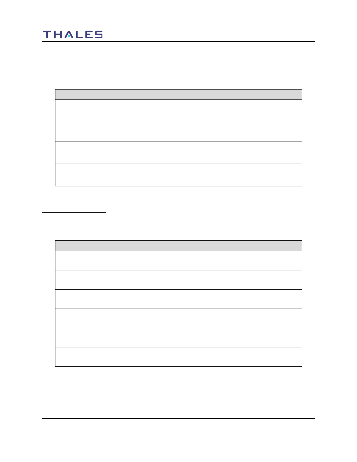
ACCESSORIES/ANCILLARY EQUIPMENT
6-4 Doc No. 84382 Rev 2
THALES COMMUNICATIONS, INC. PROPRIETARY INFORMATION
Cables
The following cables are available for use with the radio:
Table 6-6 LibertyTM Cables
Part Number Description
1600703-1
Audio/Programming Side Connector Adapter, includes 6-pin Hirose
connector for audio and
keyfill, and USB for programming, cloning, and data transfer.
1600705-1
(FUTURE)
Universal Cable, cable with flying leads to connect radio to user-specific
applications
3100965-501
PC Programming Cable Kit, consists of 1600703-1 Audio / Programming
side connector adapter and COTS USB Type A male / Mini-AB cable.
Used to connect radio to PC for programming.
3100966-501
(FUTURE)
Radio Cloning Cable Kit, consists of two (2) 1600703-1 Audio /
Programming side connector adapters and COTS USB Mini-AB / Mini-
AB cable. Used to connect two radios together for channel cloning.
Surveillance Equipment
The following surveillance equipment is available for use with the radio:
Table 6-7 LibertyTM Surveillance Equipment
Part Number Description
1600497-1
(FUTURE)
Security Harness (3 Wire), Tan in color with wired earpiece. Requires
audio / programming Side Connector Adapter, PN 1600703-1.
1600497-2
(FUTURE)
Security Harness (3 Wire), Black in color with wired earpiece. Requires
audio / programming Side Connector Adapter, PN 1600703-1.
1600497-3
(FUTURE)
Security Harness (2 Wire), Tan in color with wired earpiece. Requires
audio / programming Side Connector Adapter, PN 1600703-1.
1600497-4
(FUTURE)
Security Harness (2 Wire), Black in color with wired earpiece. Requires
audio / programming Side Connector Adapter, PN 1600703-1.
1600497-6
(FUTURE)
Wireless Earpiece for Security Harness, requires 1600497-8 neck loop
transductor
1600497-8
(FUTURE)
Neck Loop Transductor, for wireless earpiece

GLOSSARY
Doc No. 84382 INITIAL PILOT FIELD TRIALS VERSION – JAN 2009
THALES PROPRIETARY INFORMATION 7-1
CHAPTER 7 GLOSSARY
This glossary contains a listing of Acronyms’ and Definitions that are applicable to the LibertyTM Radio.
ACRONYMS’
Term
Description
AES
Advanced Encryption Standard
AN
Analog Narrowband
AW
Annalog Wideband
BIT
Built-In-Test
CDCSS
Continuous Digital Coded Squelch System
CDCSS (also DCS)
Continuous Digital Controlled Squelch System
CTCSS
Continuous Tone-Controlled Squelch System
CTCSS
Continuous Tone Coded Squelch System
DES
Data Encryption Standard
DTMF
Dual-Tone Multi-Frequency (DTMF)
GPS
Global Positioning System
HMI
Human-Machine Interface
IBIT
User Initiated Built-In-Test
KEK
Key Encryption Kay
LCD
Liquid Crystal Display
LMR
Land Mobile Radio
NAC
Network Access Code
OTAP
Over-The-Air-Programming
OTAR
Over-The-Air-Rekeying
OTG
On-The-Go
P25
Project 25 (Digital)
POST
Power-On-Self Test
PTT
Push-to-Talk
QRG
Quick Reference Guide
RF
Radio Frequency
RFSS
RF Sub-System
RSSI
Received Signal Strength Indicator
RX NAC
Receive Project 25 Network Access Code
RX TG
Receive Talk Group
SMS
Short Message Service
TEK
Traffic Encryption Key
TG
Talk Group

GLOSSARY
7-2 Doc No. 84382 Rev 2
THALES COMMUNICATIONS, INC. PROPRIETARY INFORMATION
Term
Description
TX NAC
Transmit Project 25 Network Access Code
TX TG
Transmit Talk Group
USB
Universal Serial Bus
XCVR
Transceiver
DEFINITIONS
Term Definition
Active Channel The Selected Channel is receiving a signal that is of sufficient strength to
overcome the programmed squelch level.
Bank A bank is a group of zones. Zones can be assigned to banks during
programming. The radio can store up to sixteen banks consisting of 16
zones each. Banks may be assigned names of up to eight characters
Carrier Squelch (CSQ) Carrier Squelch (CSQ) is a squelch system based on RF signal present.
It is adjustable and is also commonly referred to as Noise Squelch.
Channel (xx channels) A group of characteristics, such as transmit / receive, radio
parameters, encryption coding. Squelch, modulation, and power settings.
Continuous Digital Coded
Squelch System (CDCSS) CDCSS is a 23 bit data stream that is sent at a bit rate frequency of 134.4
Hz. It is also filtered prior to sending audio to the speaker. It is not
widely used, but is also known by other names such as DCS, DPL, and
others.
Continuous Tone Coded
Squelch System (CTCSS) CTCSS is an audio tone between 67.0 Hz and 254.8 Hz that is attached
to the RF signal. It is used to filter out all unwanted communications
present on that channel. The tone is filtered out of the signal prior to
sending the demodulated audio to the speaker, which is why it is not
heard. It is known by several brand names, such as Private Line, PL,
Code Guard, and CG amongst others.
Typically CTCSS tones are used by repeaters to filter out unwanted
signals and also on a direct radio system to enable frequency sharing.
Control Channel In a trunking system, one of the channels that is used to provide a
continuous, two-way / data communications path between the central
control and all radios on the system
Conventional Typically refers to radio-to-radio communications, sometimes through a
repeater. The user shares a frequency, or frequencies, with other users
without the aid of a central controller to assign communication channels.
Therefore, the user should monitor each channel before transmitting to
avoid interfering with another user who may be transmitting.
HOME Channel The Selected Channel when Scan is activated becomes the HOME
channel. It is added to the active Scan Plan if not already included.
Initial Synchronization Initial synchronization controls the length of time that the radio sends out
a bit synchronization pattern.

GLOSSARY
Doc No. 84382 INITIAL PILOT FIELD TRIALS VERSION – JAN 2009
THALES PROPRIETARY INFORMATION 7-3
Term Definition
Monitor Time
The Monitor Time is the amount of time the radio will sample a channel
picked up during a scan before the radio returns to scan operation. At
the end of the monitor period, the radio will break reception and continue
with the scan sequence. The Monitor Time can be programmed for OFF
(default) or ON.
Network Access Code
(NAC)
NAC is a digital code providing filtering of unwanted signals. It is
typically used to replace the CTCSS tones used for Repeater Access.
There are 4096 possible NACs, which are represented either in
hexadecimal format (0-FFF) or decimal (0-4095) or both.
Open Channel The squelch setting is overridden and the radio is in a constant receive
state.
Quick Call The QUICK CALL screen displays the various call choices for the user.
Radio Set Identifier (RSI) RSI (Radio Set Identifier) is similar to a UnitID, and is typically set to the
same value, although not required. It is used to gain access into a network.
RSI’s are typically used for network authentication reasons
Scan Hold Timer If Talkback is disabled, the Scan hold Timer allows a user to monitor a
channel that was picked up while scanning prior to re-entering the scan
sequence. In addition, if Talkback is disabled, the Talkback Scan Timer is
not used.
Selected Channel The Channel/Frequency currently loaded into the radio for
Receiving/Transmitting operations.
Squelch The muting of audio circuits when received signals levels fall below a
pre-determined threshold. With carrier squelch, the user will hear all
channel activity which exceeds the radio’s preset squelch level.
Standby An operating condition whereby the radio’s speaker is muted but still
continues to receive data.
Subscriber Unit (SU) Subscriber Unit is a generic name used for a mobile or portable radio
unit that can terminate voice or data messages in a radio system.
Talk Around Toggles channels enabled for talk around from talk around mode to
repeater mode. Talk Around allows radio users to bypass a repeater and
talk direct (DIRECT, CAR-CAR, TAC, etc) on a repeater channel.
NOTE that the channels MUST have Talk Around enabled from the PC
Programmer for this to have any affect.
Talk-Group (TG) TG has multiple applications for Project 25. For conventional Project 25
channels, talkgroups are an additional method of breaking up channels,
providing a means for several groups to share a repeater without
disturbing one another (repeaters can re-transmit only one signal at a
time). For trunked channels, talkgroups indicate where the control
channel directs the radio. There are 65535 possible TGs, represented in
hexadecimal format (FFFFFF) or decimal (0-65535).
Transmit (TX) Timeout The radio can be programmed to end transmission automatically after a
pre-determined length of time in transmit mode. The radio gives a
warning tone and visual indication immediately before ending

GLOSSARY
7-4 Doc No. 84382 Rev 2
THALES COMMUNICATIONS, INC. PROPRIETARY INFORMATION
Term Definition
transmission. The visual indication ("TIME" on the front display)
continues until the radio exits transmit mode or the radio is unkeyed,
whichever comes first.
UnitID
UnitID (Unit Identifier) is a unique parameter that specifies one
particular radio. It can be used to identify an incoming call or to initiate
a unit-to-unit call. There are over 16,777,215 possible values. Every
Project 25 device (handhelds, mobiles, repeaters, base stations, consoles,
etc) may be assigned a UnitID
Zone
A zone is a group of channels. Each zone can be assigned up to 16
channels. The radio can store up to 16 zones, or groups of channels.
Zone
A zone is a group of channels. Each zone can be assigned up to 16
channels. The radio can store up to 16 zones, or groups of channels.

APPENDIX A
APP-A-1
APPENDIX A – QUICK REFERENCE GUIDE
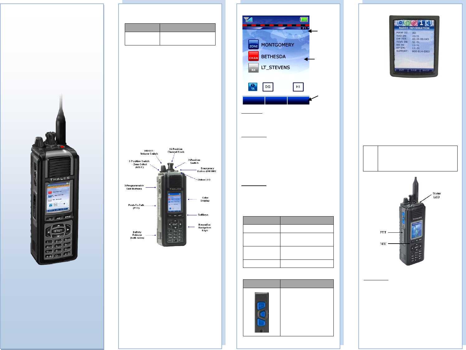
Stats
Area
Context area
Softkey
Menu
ANTENNAS
Antenna PN Frequency Range
1600678-1 136-174 MHz, 380-520
MHz, and 763-869 MHz
INITIAL SET-UP
1. Attach a charged LIBERTYTM rechargeable
battery to the radio.
2. Attach the antenna by twisting clockwise until it
is secured to the radio antenna connector.
3. Use the ON/OFF/Volume control switch on top
of the radio to turn on the radio.
4. Turn the channel select switch on top of the
radio to the desired operating channel.
5. Use the ZONE Select (A/B/C) Switch to change
zones.
CONTROLS, INDICATORS,
and KEYPADS
WHAT IS THE RANGE?
• Range is line of sight. If you can see the
antenna location, you are in range.
• On flat land, horizon is the limiting factor –
will get 5-6 miles
• Range can be extended by elevating an
antenna (or using repeaters)
• Best range when antenna is held vertical and
away from body.
• Use maximum RF output for best range (VHF,
UHF: 5W, 700 MHz: 2.5W, 800 MHz: 3W)
2
Operating Screen:
Status Area
• Received Signal Strength
• Battery Charge Status
• High / Low TX Power Settings
Context Area:
• Current Zone Name
• Current Channel Name
• Zone and Group Information
• Communication Mode (Talk-Around or Repeater)
• Channel Type (AN, AW, or P25)
• P25 ID Display (Also see P25 Unit to Unit Call)
• P25 Unit Call Status (Also see P25 Unit to Unit
Call)
Softkey Menu
(displays programmed softkeys only)
• Menu
• PRIV (Private Call )
• TLKARND (Talk Around)
LED Indicators:
LED Indicator What it Means
RED Radio Transmitting
Flashing RED Low Battery (while
transmitting)
GREEN Receiving/Busy Channel
Indication
0FF Standby
Programmable Side Buttons:
Side Buttons Programmable* Options
Each button can be pre-
programmed:
• Hi/Lo Power
• Monitor
• Scan
• Priority Scan
• Talkaround
*Pre-Programmed via
PcProgrammer
3
Liberty
TM
Multiband
Land Mobile Radio
Quick Reference
Guide
APRIL 2009
Refer to the LIBERTYTM User’s Guide (PN 84382)
for additional detailed information on radio
operation.
Radio Information Menu:
VIEWABLE access to all users for:
• Manufacturer information
• Radio Serial Number (SN)
• Software Version
• Transceiver Serial Number (SN)
• Baseband Serial Number (SN)
• Keypad Serial Number (SN)
• Customer Support phone number
TRANSMITTING / RECEIVING
!
NOTE
Prior to transmitting, verify that the LED
is NOT illuminated GREEN (solid or
flashing). This indicates RF traffic on
that channel. Wait for it to clear.
Transmitting
To Transmit:
• Push the PTT button
• Speak into microphone (3-6 inches)
LED Transmit indications
• OFF – not transmitting or receiving
• RED – transmitting
Transmitting with Speaker/Mic
• Push PTT on speaker/mic
• Speak into speaker/mic
4
Status
Area
Context
Area
Softkey
menu
MENU
PRIV
TLKRND
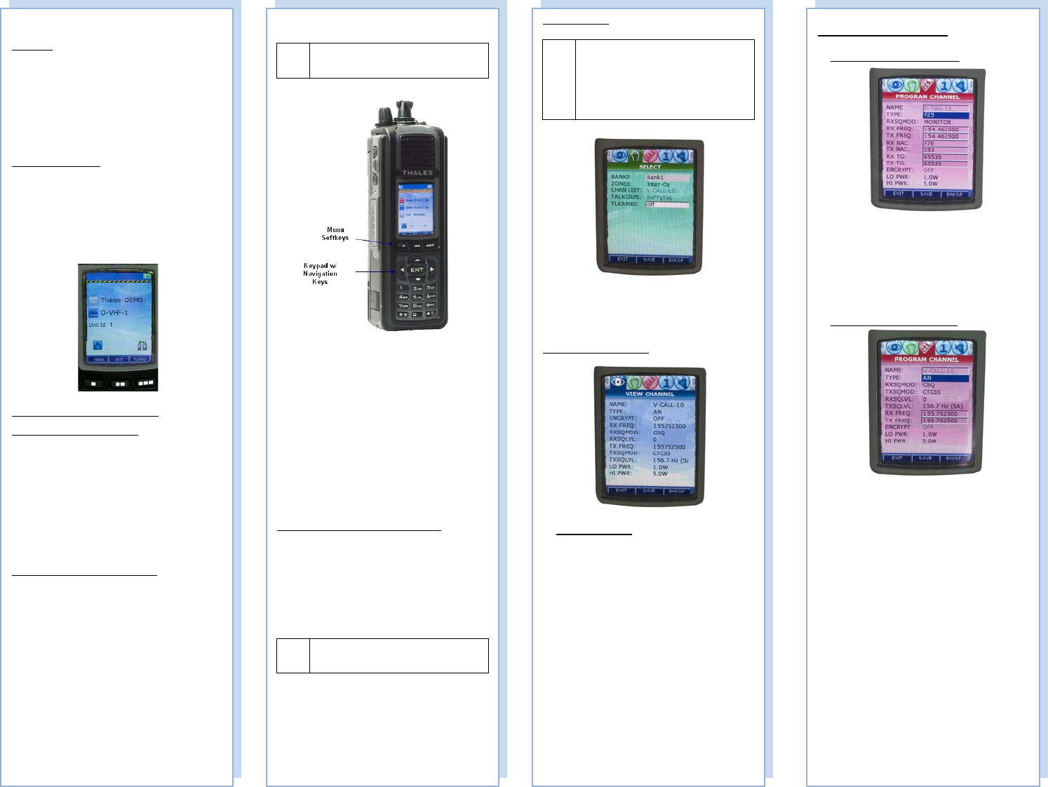
MENU ACCESS:
! NOTE
Some or all menus may not be accessible
due to password protection (future).
• PRESS MENU softkey or NAV ENTER
button to access menus
• Once in MENUS, use the left/right arrow keys
to scroll to the desired parameter.
• To Edit/Modify an entry -- either press ENT
to view the drop down menu. Or use the
numeric keypad to enter the required data.
• To save changes, first press SAVE, then use
the arrow up key to get to the top of the menu,
the use the left/right arrows to scroll to the
next menu.
• To EXIT -- Press EXIT to return to HOME
Channel.
LCD and Keypad Backlight/Screen Saver
The user may turn on the backlighting for the
display, keypad, and channel numbers (around the
16-position Select knob), by pressing any key,
button, or turning any knob. These lights will remain
on for a pre-determined time period before they turn
off automatically.
!
NOTE
Screen Options that are grayed out – are
not available this version of software.
6
SELECT Menu
!
NOTE
The Channel List and Talk Groups on
this screen are currently grayed out and
cannot be modified in this version of
software. To change channels, use the
Channel Knob located on top of the
radio.
• Select Banks (collection of zones)
• Select Zones (collection of channels/TG’s)
• Turn Talk-Around ON or OFF (FUTURE)
VIEW CHANNEL Menu
VIEW access only
• View Channel parameters
7
PROGRAM CHANNEL Menu
PROGRAM CHANNEL – P25
• The Channel name is displayed.
• Select the waveform TYPE P25
• Enter the RX/TX Freq
• Enter the RX/TX NAC
• Enter the RX/TX TG
• Turn ENCRYPT ON or OFF
• Adjust the LO/HI Power Setting
PROGRAM CHANNEL – AN
• The Channel name is displayed.
• Select the waveform TYPE AN
• Enter the RXSQMOD (CSQ, CTCSS, CDCSS)
• Enter the TXSQMOD (OFF, CTCSS, CDCSS)
• Enter the RXSGLVL (0-16, 0 is open squelch)
• Enter the TXSQLVL
• Enter the RX/TX Freq ranges
• Adjust the LO/HI Power Setting
8
Transmitting/Receiving (cont.):
Receiving
Conventional Channels Talkgroups
• Verify PTT is NOT depressed
• Audio will come from speaker (or speaker/mic)
LED Receive indications
• OFF – not transmitting or receiving
• GREEN – receiving signal
P25 Unit to Unit Call
To place a call within your unit,
1. Press the PRIV Softkey from the HOME
screen.
2. Enter the Unit ID number.
3. Press enter, then press PTT to initial the call.
The Unit ID will be active until a different
channel is selected, or the user presses EXIT.
SCAN – Conventional and Priority
Enable SCAN – two (2) options:
1. Press the MENU Key and navigate to the scan
menu and select SCAN and set to ON. Scanning
will start immediately when ON is selected. Once
the SCAN function is set to ON, exit the SCAN
Menu Screen.
OR
2. Press one of the side buttons that has been pre-
programmed to SCAN.
Enable PRI SCAN – two (2) options:
1. Press the MENU Key and navigate to the scan
menu and select SCAN, select PRI SCAN, and set
to ON. Scanning will start immediately when
ON is selected. Exit the SCAN Menu Screen.
OR
2. Press one of the side buttons that has been pre-
programmed to PRI SCAN.
5
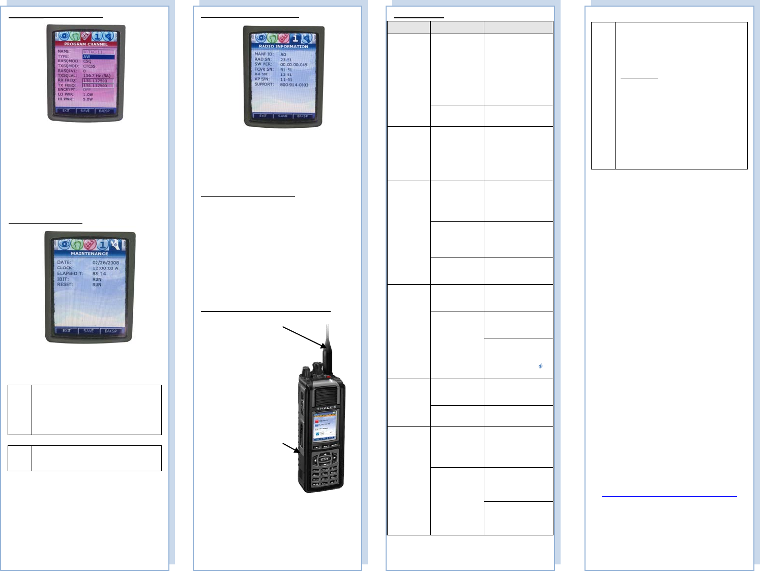
PROGRAM CHANNEL – AW
• The Channel name is displayed.
• Select the waveform TYPE AW
• Enter the RXSQMOD (CSQ, CTCSS,
CDCSS)
• Enter the TXSQMOD (OFF, CTCSS, CDCSS)
• Enter the RXSGLVL (0-16, 0 is open squelch)
• Enter the TXSQLVL
• Enter the RX/TX Freq ranges
• Adjust the LO/HI Power Setting
MAINTENANCE Menu
• View Maintenance Information
!
NOTE
This screen is temporarily being used for
Downloading Radio configuration file to
radio (puts radio in program mode by
being on this screen) – for future releases
of the radio – this will be automatic.
! NOTE
The radio does not transmit or receive
while on the Maintenance Screen.
9
!
NOTE
LIBERTYTM RADIOS
Please use the following field support
contact information:
Contact Info:
Bob DiDonato,
Thales Communications, Inc.
Mobile: 1-410-908-7678
Email:
Bob.DiDonato@thalescomminc.com
Scott Glazer,
Thales Communications, Inc.
Mobile: 1-240-422-2612
Email:
Scott.Glazer@thalescomminc.com
APRIL 2009
THALES COMMUNICATIONS, INC.
22605 GATEWAY CENTER DRIVE
CLARKSBURG, MD 20871
Customer.Service@thalescommunications.com
P/N: 3401448-1, Rev 2
12
Troubleshooting
Symptom Probable Cause Corrective Action
Radio does
not operate • Battery not
properly
connected
• Before removing
battery from the radio,
make sure the radio is
turned-off first.
• Remove and re-
install battery – be sure
to clean the battery
contacts before re-
installing the battery.
• Battery dead • Either Charge or
Replace battery
Screen Blank • Radio in screen
saver mode
• To re-activate the
screen – press PTT,
change the volume or
channel, or press any
key. The screen will
also be re-activated
when a call is received.
Cannot
communicate
with other
radio users
• Radios set to
different
frequencies
• Set all radios to the
same frequency (can be
accomplished by
loading from PC
Programmer).
• Radios are set
with different
CTCSS tones
• Set receive and
transmit CTCSS tones
the same in all radios
• Radios set to
different
modulation types
• Set Radios to same
modulation types
External
Speaker/Mic
not working
(no audio)
• External
Speaker/Mic not
properly installed
• Verify speaker / mic
is attached correctly.
• No audio
• Remove and replace
the external audio
speaker/microphone
• Check the INT/EXT
Audio Switch -
Functionality –
EXT/INT Audio (“ ”
EXT and “0” INT)
Radio does
not scan • SCANLISTS
not programmed
into radio
• Set SCANLISTS in
PcP and download to
radio
• SCAN is not set
to ON • Set SCAN to ON via
the SCAN Menu
Radio does
not
communicate
with Pc
Programmer
• Pc Programmer
not installed
correctly.
• Refer to Pc
Programmer Manual
for installation
instructions of the
software.
• Pc Programmer
Cable not
connected
properly
• Check cable
connections, remove
and re-attach Pc
Programmer cable.
USB Driver not
installed or Network
settings not properly
configured.
11
RADIO INFORMATION Menu
• View Radio Information
MAINTENANCE
Radio Preventive Maintenance
• Check the radio for external damage, such as
bent connectors and possible loose hardware.
• Periodically clean the radio, especially after
exposure to salt water, sand, or mud.
• Wipe the exposed contacts (side connector,
battery connector) with fresh water and then
dry with low pressure air, if available.
• Small particles of dirt and debris may infiltrate
the grill of the speaker/microphone and should
be cleaned using a small brush or low pressure
air, if available.
Battery and Antenna Installation/Removal
10
ANTENNA
• Twist clockwise until
fully seated to install
• Twist
counterclockwise to
remove
• DO NOT carry radio
by antenna.
BATTERY
• Install and Remove
by pressing tabs on
both sides to release
• To install, insert top
of battery under flap
at top and click tabs
in place at bottom
• To remove, press
tabs and lift out from
battery (recommend
turning radio OFF
first)

THIS PAGE INTENTIONALLY LEFT BLANK

INDEX
Doc No.: 84382 Rev 2 Index-1
INDEX
Available Accessories / Ancillary Equipment
Antennas ........................................................... 6-1
Audio Accessories ............................................ 6-3
Batteries ............................................................ 6-2
Battery Chargers ............................................... 6-2
Cables ............................................................... 6-4
Cases / Holsters ................................................. 6-3
Surveillance Equipment .................................... 6-4
Battery Chargers
Electrical Characteristics .................................. 5-2
General Information .......................................... 5-1
Operating Indications ........................................ 5-3
Performance ...................................................... 5-2
Physical Characteristics .................................... 5-2
Battery Chargers - Physical Characteristics
Temperature ...................................................... 5-2
Weight and Dimensions .................................... 5-2
Connectors
Antenna Connector ......................................... 1-13
Battery Connector ........................................... 1-14
Side Connector ................................................ 1-12
Controls
Four Way Navigation Buttons w/ Enter Button 1-9
Side Buttons .................................................... 1-10
Special............................................................... 1-8
Controls and Indicators
Controls............................................................. 1-7
Indicators ........................................................ 1-11
Display / Menu Screens
Display/ MENU SCREENS .............................. 2-2
General Information .......................................... 2-1
HOME Screen ................................................... 2-3
MENU Screen Displays .................................... 2-6
PROGRAM Menu Screen................................. 2-9
SELECT Menu Screen ...................................... 2-7
SPLASH Screen ................................................ 2-2
VIEW Menu Screen .......................................... 2-8
Getting to Know the Radio
Controls and Indicators ..................................... 1-7
Equipment Characteristics ................................ 1-2
General Information .......................................... 1-1
Liberty Radio – Location of Controls and
Indicators ...................................................... 1-4
Technical Characteristics .................................. 1-3
Glossary
Acrynoms .......................................................... 7-1
Definitions ........................................................ 7-2
HOME Screen
Context Area ..................................................... 2-4
SoftKeys Area ................................................... 2-5
Status Area ........................................................ 2-3
Indicators
Connectors ...................................................... 1-12
LCD and Keypad Backlight ............................ 1-11
LED Indicators ................................................ 1-11
Maintenance
External Battery Preventive Maintenance ......... 4-2
General Information .......................................... 4-1
Operational Checkout ....................................... 4-2
Radio Disassembly ........................................... 4-5
Radio Preventive Maintenance ......................... 4-2
Removal/Replacement Procedures - Operator .. 4-4
Troubleshooting ................................................ 4-3
Operating Instructions
Changing ZONES ............................................. 3-9
Connecting the Antenna .................................... 3-1
Connecting the Battery ..................................... 3-1
General Information .......................................... 3-1
Menu Access ..................................................... 3-3
Modifying Menu Selections – SELECT Menu or
PROGRAM Menu ........................................ 3-9
Operating Instructions ....................................... 3-1
P25 Unit to Unit Call ........................................ 3-5
Radio Programming .......................................... 3-1
Receiving .......................................................... 3-4
Scanning – Conventional and Priority .............. 3-6
Screensaver ..................................................... 3-10
Transmitting ...................................................... 3-4
Turning on the Radio ........................................ 3-2
Using the Pre-Programmed Side Buttons ......... 3-8
PROGRAM Menu Screen
Channel Type – Analog Narrowband (AN) .... 2-12
Channel Type – Analog Wideband (AW) ....... 2-14
Channel Type - P25 .......................................... 2-9
MAINTENANCE Menu Screen ..................... 2-19
RADIO INFORMATION Menu Screen ......... 2-18
Radio Preventative Maintenace
Inspection and Cleaning .................................... 4-2
Removal/Replacement Procedures - Operator
Antenna Removal/Replacement ........................ 4-4
Audio Accessory Removal/Replacement .......... 4-4
Battery Removal/Replacement ......................... 4-5
Scanning - Conventional and Priority
Enable SCAN .................................................... 3-6
Monitor Timer .................................................. 3-7
Priority Scan ..................................................... 3-6
Receiving a Voice Call on a Channel in the Scan
List ............................................................... 3-7
SCAN Hold Timer ............................................ 3-7
Special ................................................................... 1-9

INDEX
Index-2 Doc No.: 84382 Rev 2
THIS PAGE INTENTIONALLY LEFT BLANK
