Thales Visionix 910EWTX Motion Tracker User Manual IS 900 User Guide v61 RGH
Thales Visionix, Inc. Motion Tracker IS 900 User Guide v61 RGH
UserManual.wiki
>
Thales Visionix
>
910EWTX User Manual
>
Manual Part 1
Contents
1.
Manual Part 1
2.
Manual Part 2
Manual Part 1
Navigation menu
Upload a User Manual
Namespaces
Wiki Guide
HTML
PDF
Info
Views
User Manual
Discussion / Help
Navigation
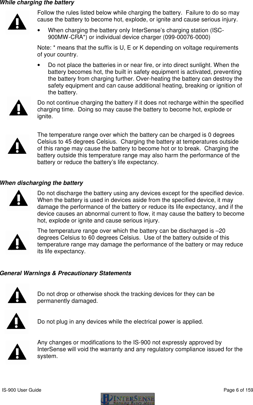
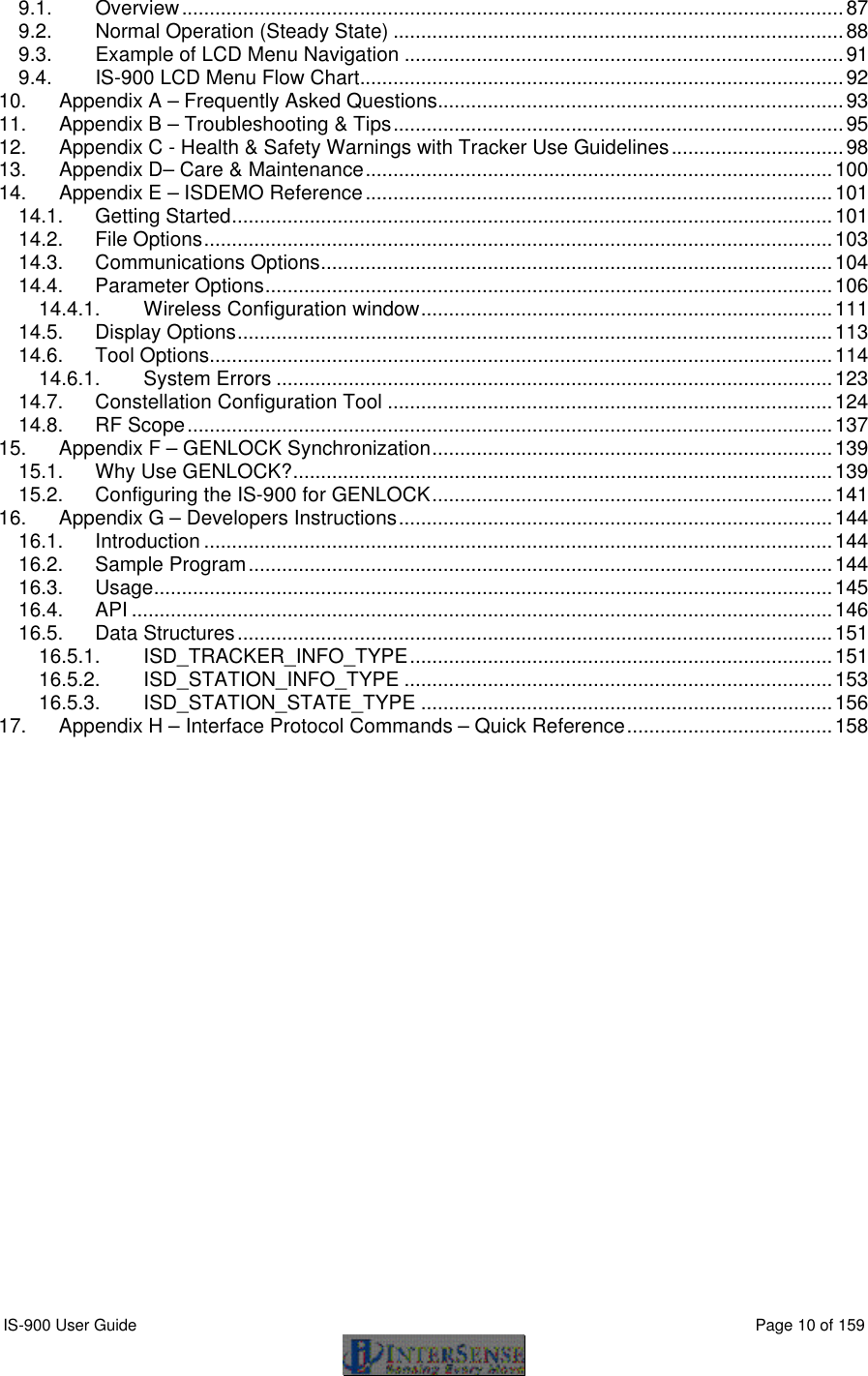
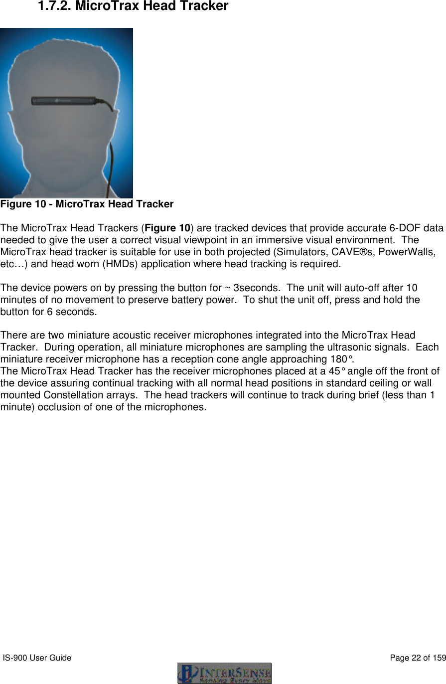
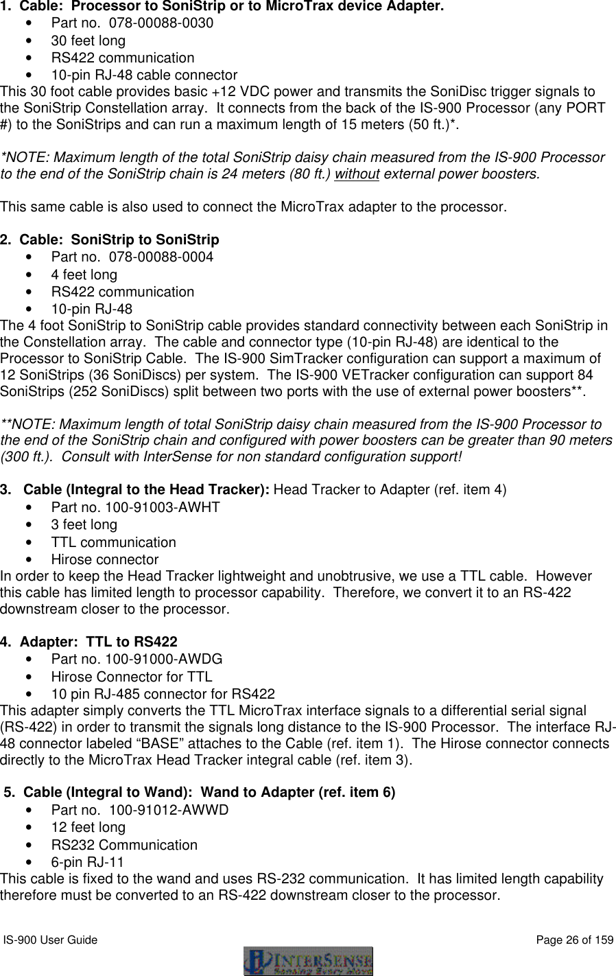
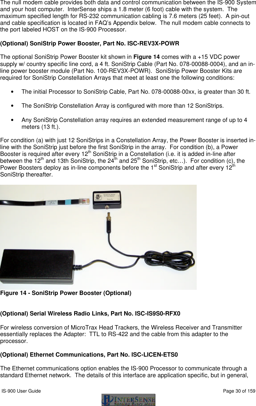
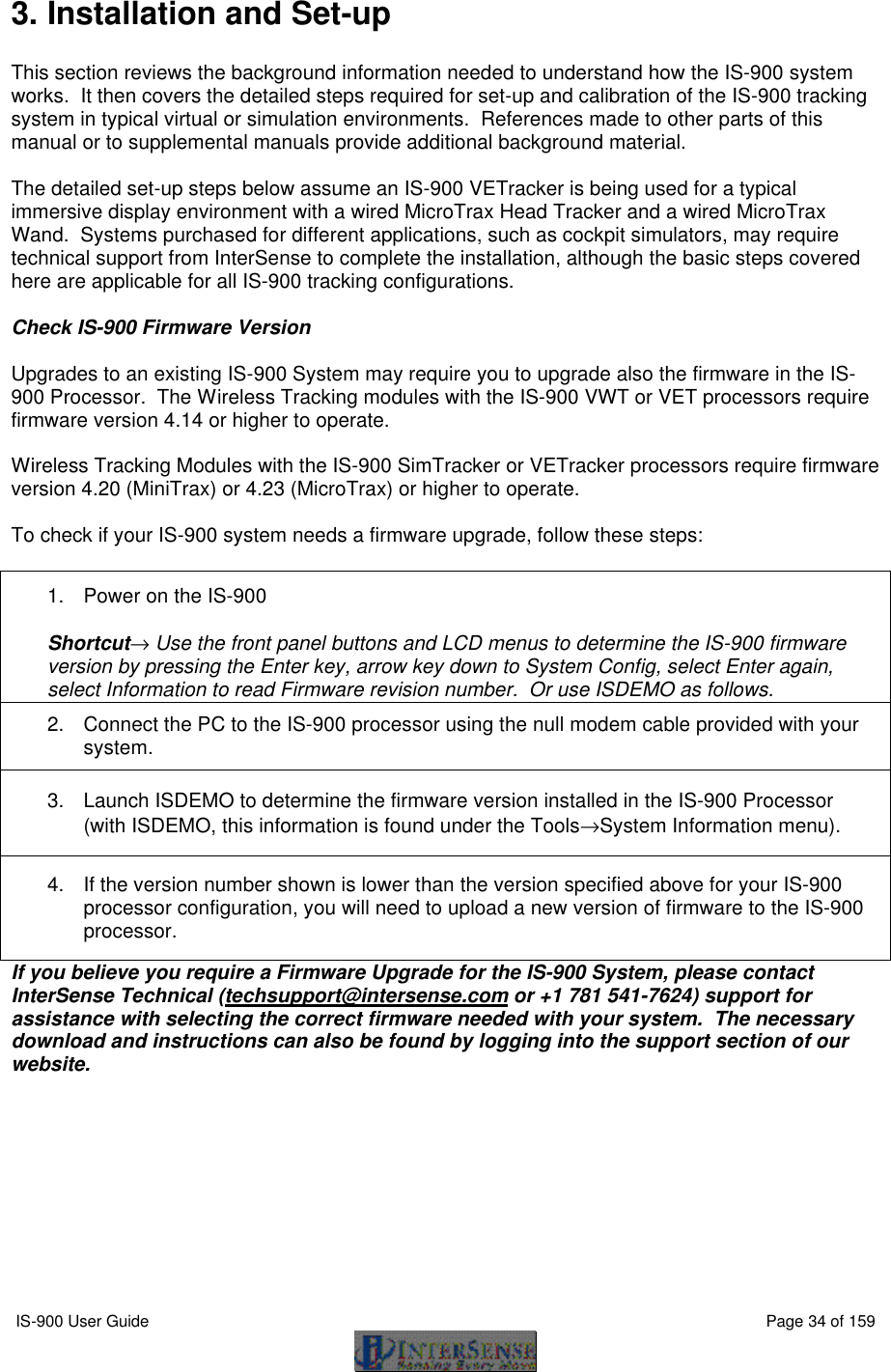
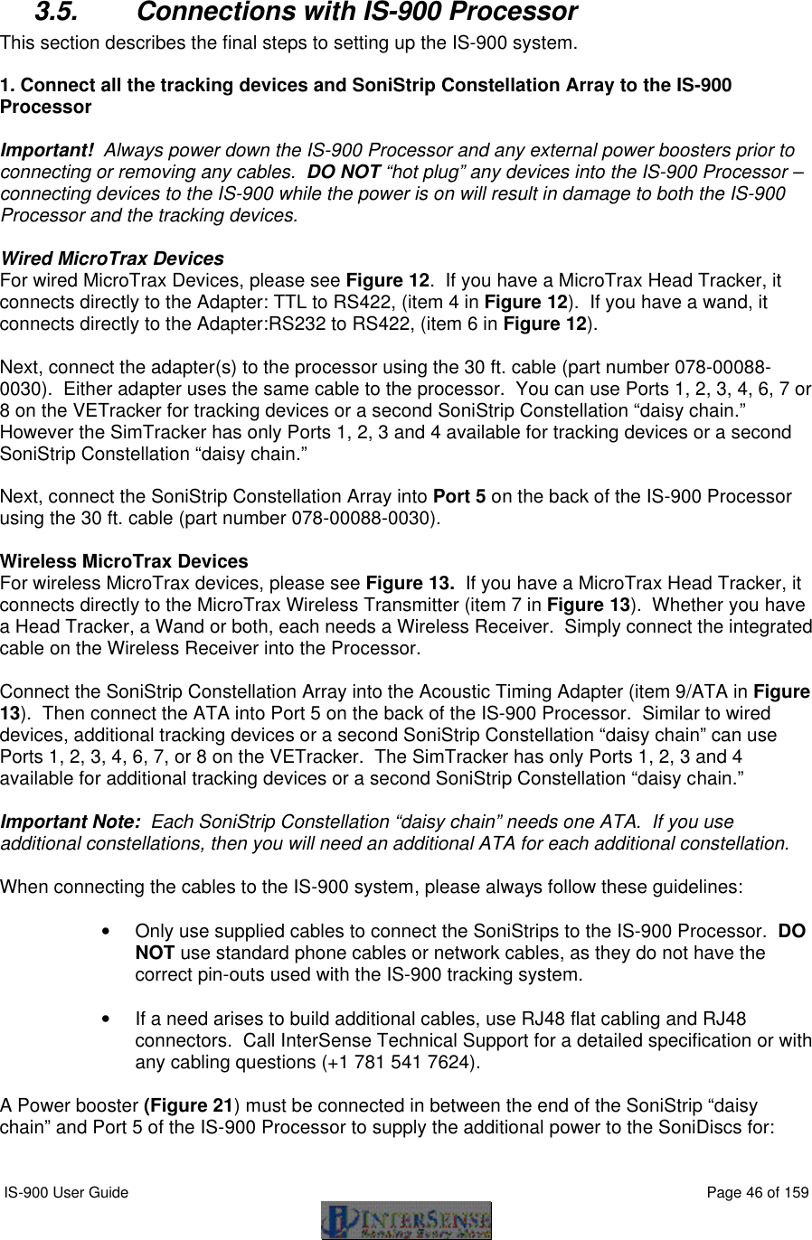
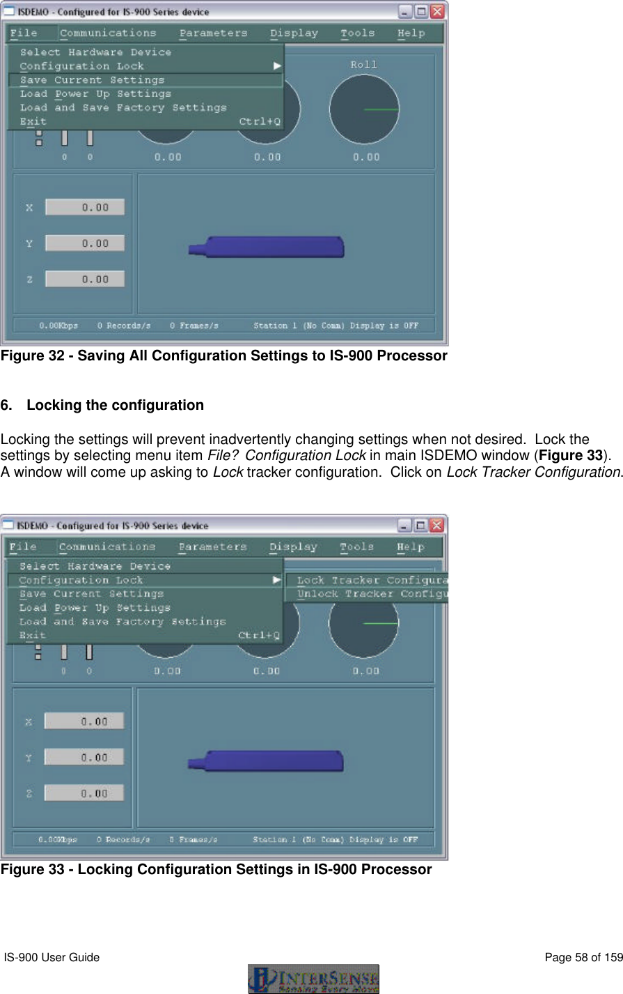
![IS-900 User Guide Page 61 of 159 8. Interface Communication Protocol For firmware version 4.20 or higher Terminology Throughout this section and the ISDEMO program described in Section 14, certain terms and acronyms are used to reference functional components of all InterSense tracking systems. Specifically, IS-900 models contain an ultrasonic subsystem that includes SoniDiscs (Ultrasonic Transponder Beacons) and Microphones (Ultrasonic Receiver Modules – URMs). To generalize the interface protocol and configuration tools for these tracker models, InterSense uses the term: PSE - Position Sensing Element. A PSE may be Mobile or Fixed. Mobile PSEs are assigned to the stations and their movements are tracked by the system (i.e. MicroTrax Microphones). Fixed PSEs form a CONSTELLATION? that is used as a reference for tracking (i.e. SoniStrips & SoniDiscs). In the case of IS-900 tracking systems, Microphones are mobile and SoniDiscs are fixed. 8.1. Commands Sent from the Host to the Tracker <> Carriage return line feed pair- not needed for single character commands. CR – ASCII value 13, LF – ASCII value 10. {} List of parameters required for command. [] List of optional parameters for command. Omitting those results in a query. The IS-900 emulates most (but not all) of the commands in the Polhemus Fastrak™ protocol, thus it is possible to use the IS-900 with most applications without writing new driver code. There are also several additional commands added to access some of the advanced features of the IS-900 that do not have any counterpart in the Fastrak™ protocol. Note: Firmware version 3.xx extended Fastrak™ protocol to support up to 32 stations (actual number allowed is determined by your hardware configuration). StationNum in commands, status and data records is now encoded in an extended hexadecimal notation. Numbers 1 to F conform to standard hexadecimal notation, with numbers greater that F represented by additional upper case letters of the alphabet. For example, number 16 is displayed as G. 8.2. Standard Fastrak™ Interface Commands Data Record Request P Request a data record from all active stations. Only used in polled mode. Output mode C Put in continuous output mode. c Put in polled output mode. Default Polled mode Alignment Reference Frame A{stationNum},[Ox,Oy,Oz,Xx,Xy,Xz,Yx,Yy,Yz]<>](https://usermanual.wiki/Thales-Visionix/910EWTX.Manual-Part-1/User-Guide-838165-Page-61.png)
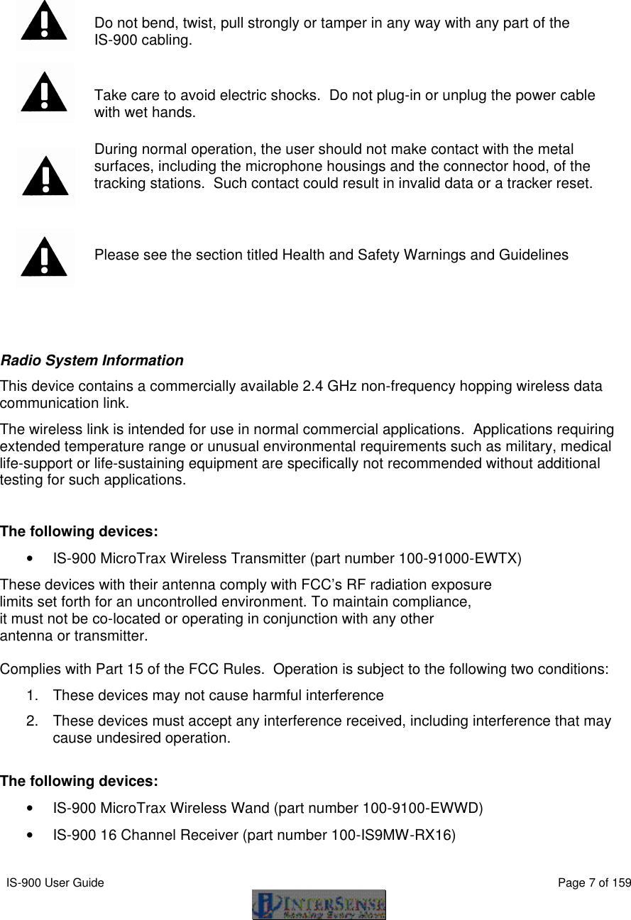
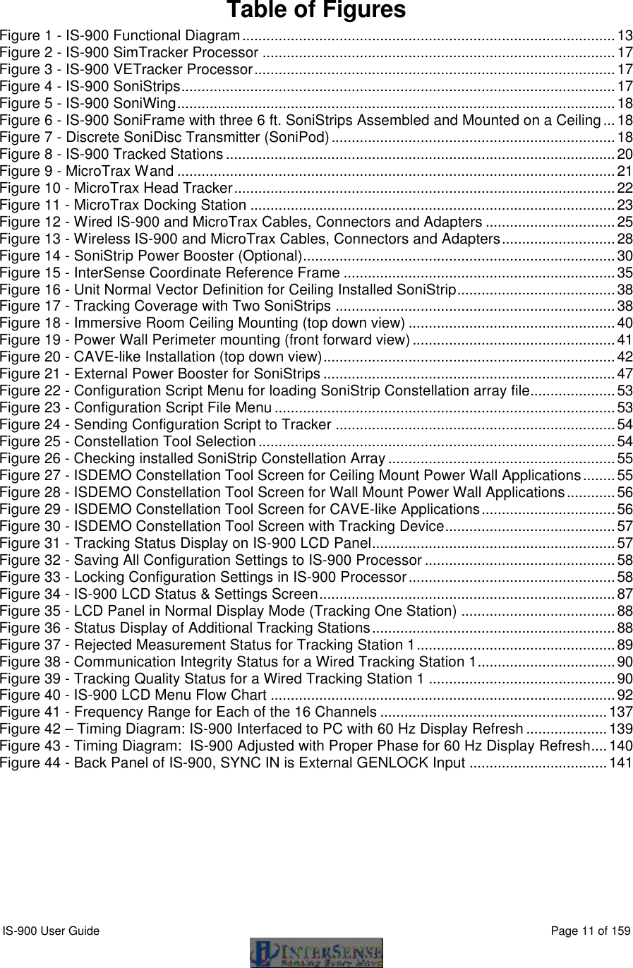
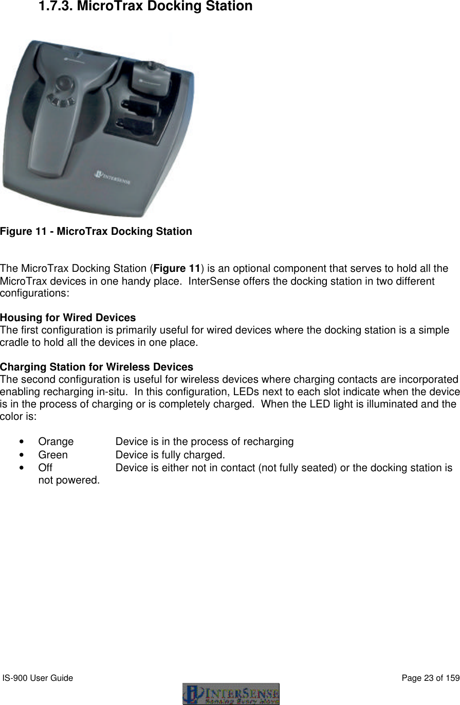
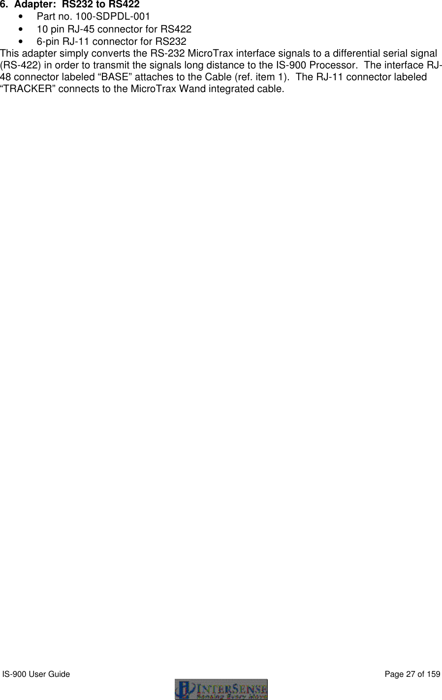
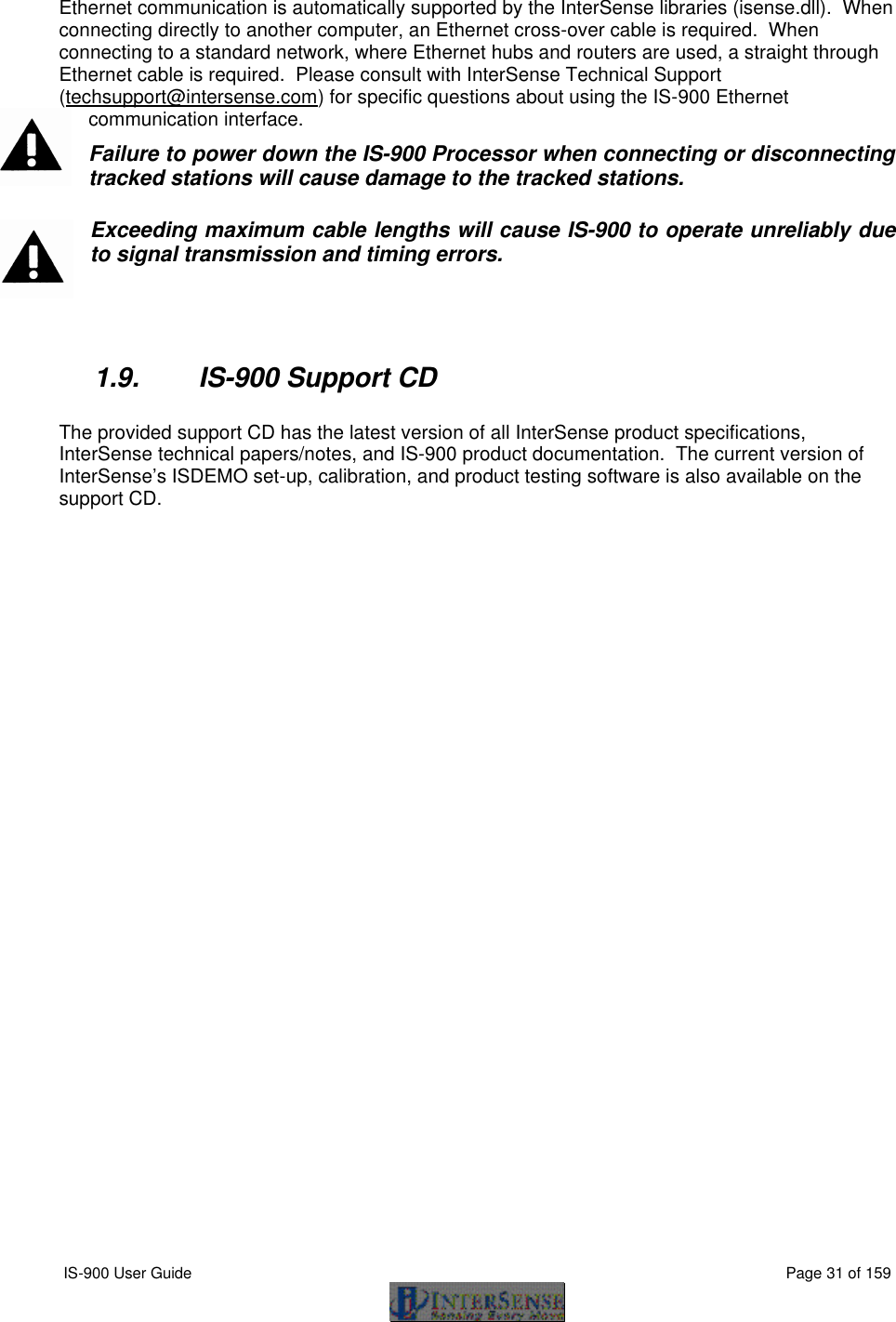
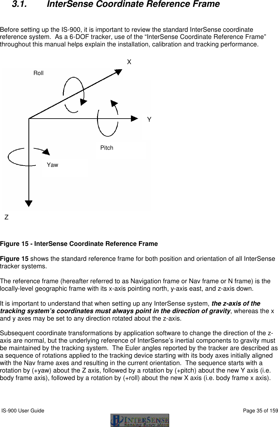
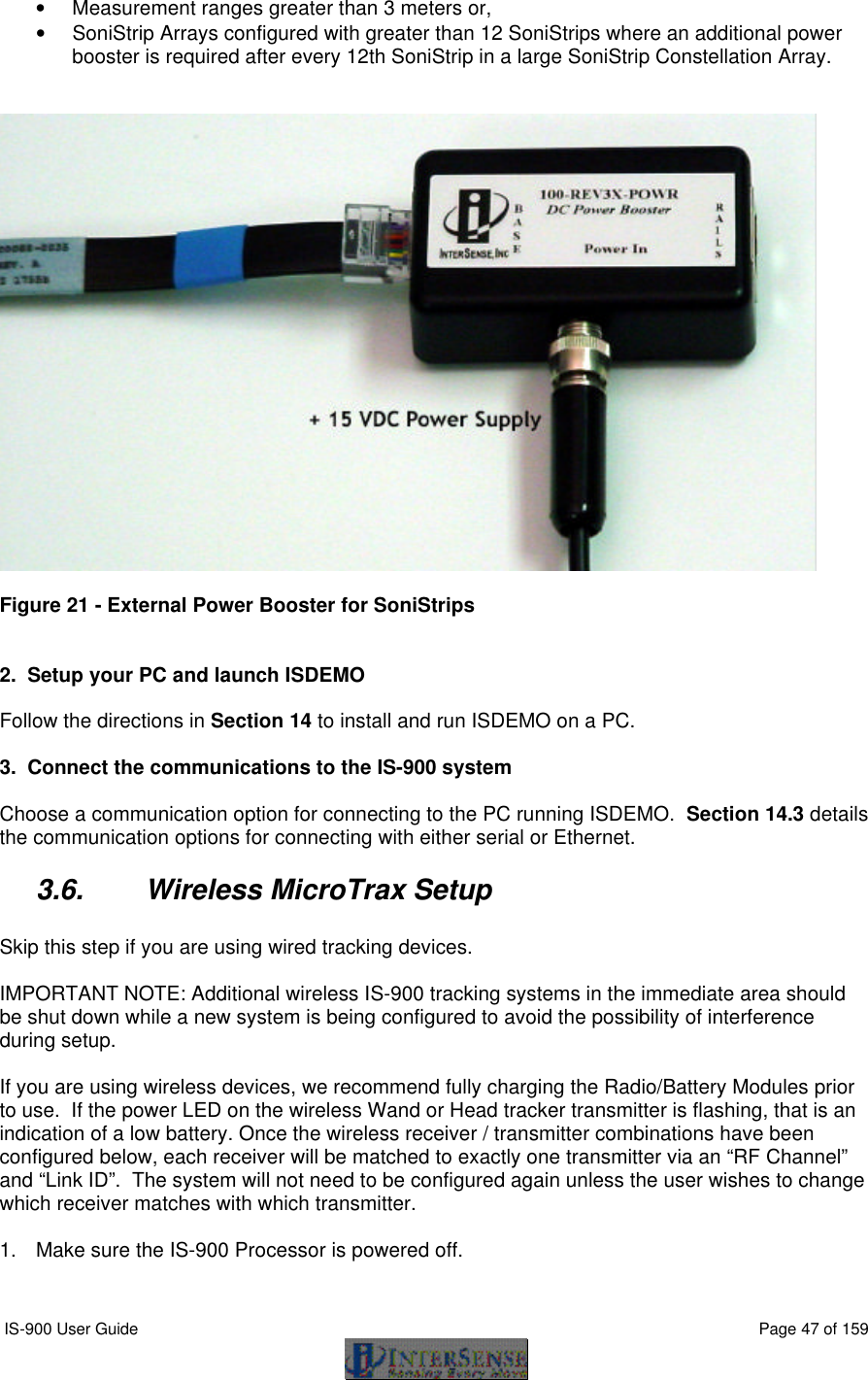
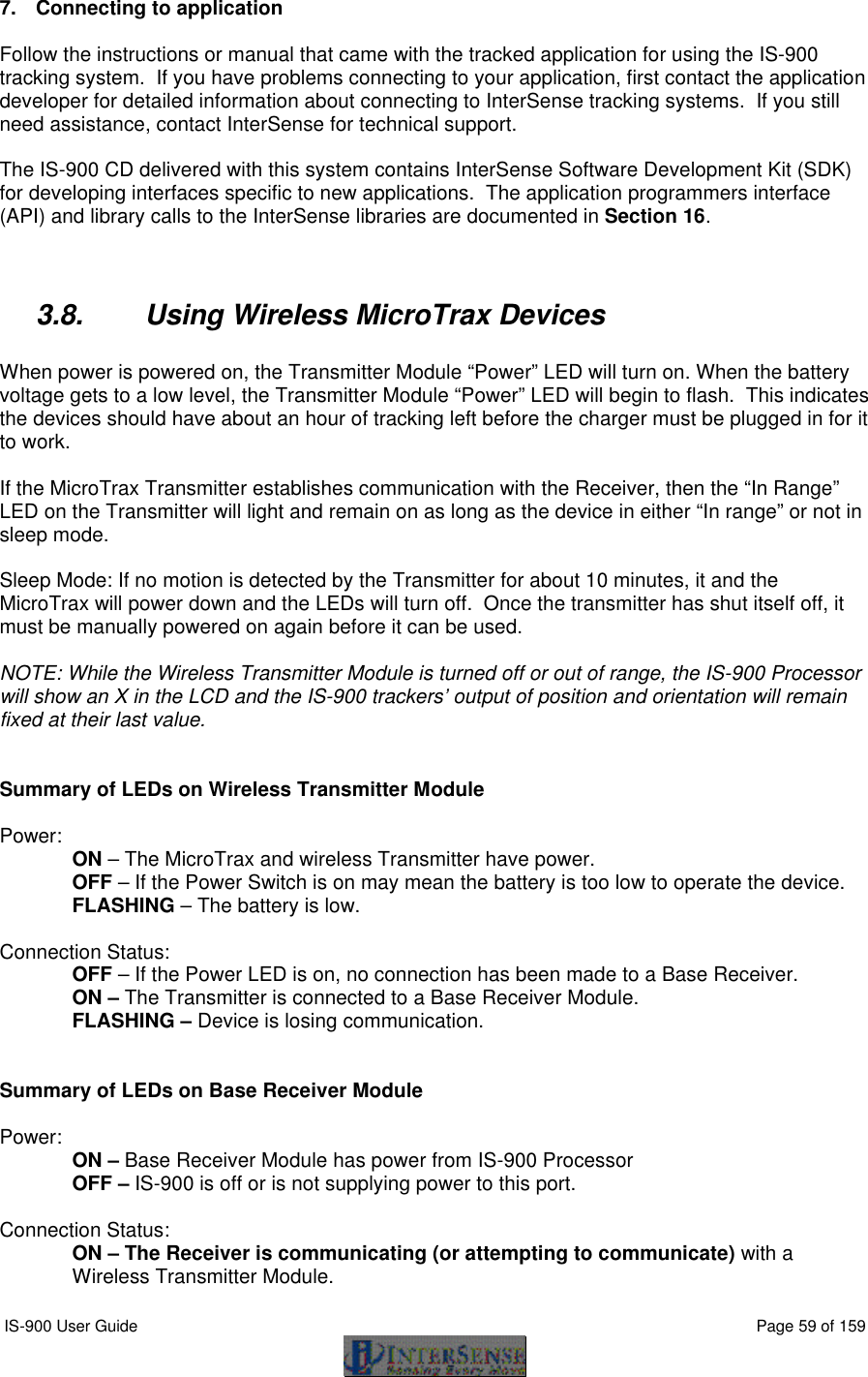
![IS-900 User Guide Page 62 of 159 Sets the coordinate frame with respect to which outputs for that station will be reported. The coordinate frame is defined by a set of three points. Ox,Oy,Oz defines the origin of the new coordinate system, Xx,Xy,Xz defines a point on the positive x-axis and Yx,Yy,Yz defines a point on the positive y-axis. The effect of this command is incremental, or relative to any current alignment reference frame already in place. If optional parameters are omitted, current values are returned. Units are centimeters. Default Fusion Mode: X=North, Y=East, Z=Down, position origin is defined by SoniStrip Constellation Array horizontally leveled. See Section 3.1. Reset Alignment Reference Frame R{stationNum}<> Resets reference frame to the default. Boresight Reference Angles G{stationNum},[yawref, pitchref, rollref]<> Sets the boresight reference angles for the specified station. If set, these values are then used by the next Boresight command instead of current orientation. If optional parameters are omitted, current reference angles are returned. Units are degrees. Default 0,0,0 Boresight Compatibility Mode MBF<> Switch system to Fastrak Compatible mode. MBI<> Switch system to Firmware Version 2.x Compatible mode. In firmware versions prior to 3.00 the B{stationNum}<> command was implemented as the Heading Boresight (see below) and full boresight was not available. To maintain compatibility with the user software written at that time, two Boresight Compatibility modes are available. In Fastrak Compatible mode B{stationNum}<> command executes full 3-DOF boresight and MB{stationNum}<> effects heading only. In the Firmware Version 2.x Compatible mode the meanings of these commands are reversed. Default Firmware Version 2.x Compatible, MBI<>](https://usermanual.wiki/Thales-Visionix/910EWTX.Manual-Part-1/User-Guide-838165-Page-62.png)
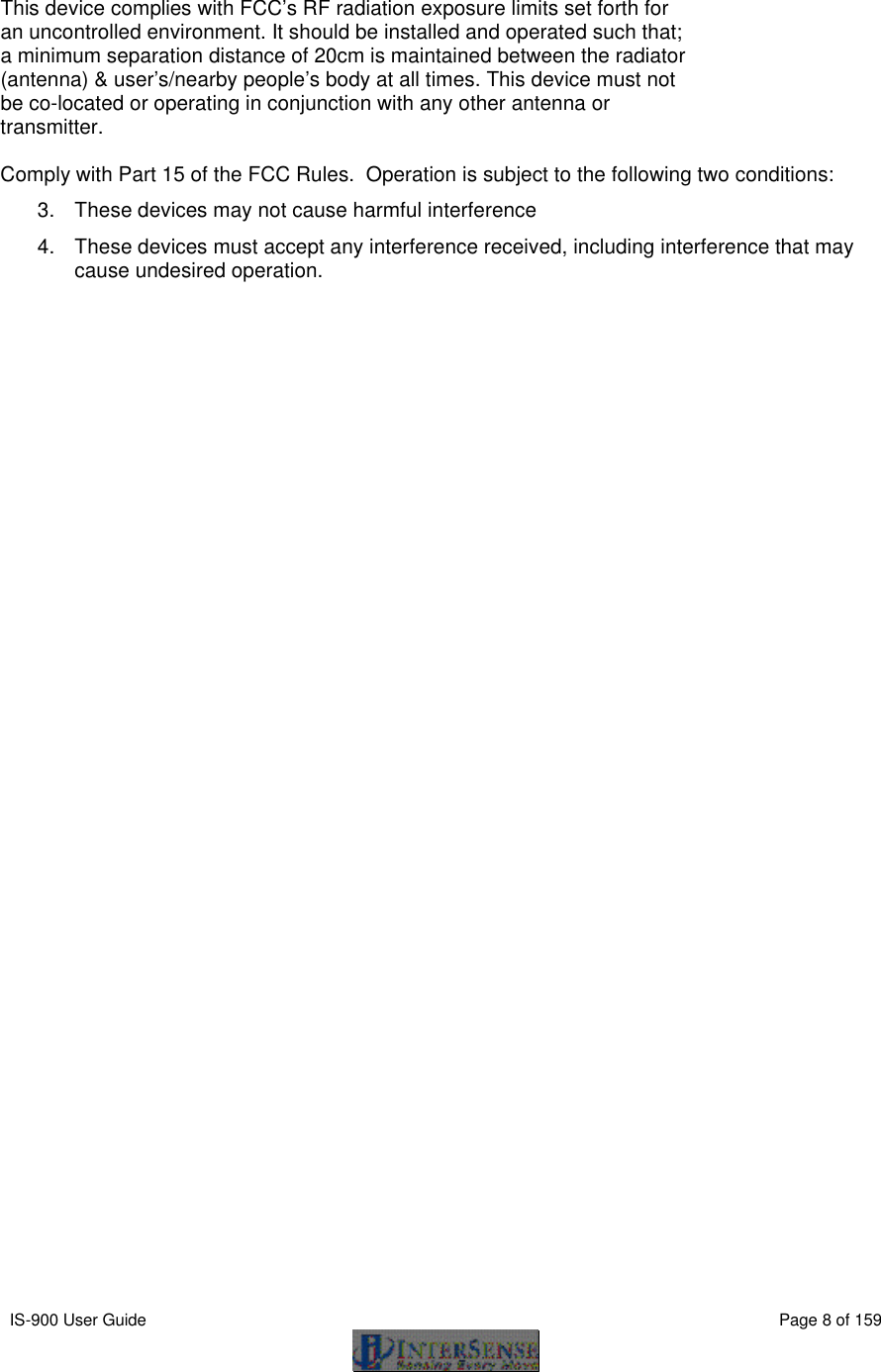
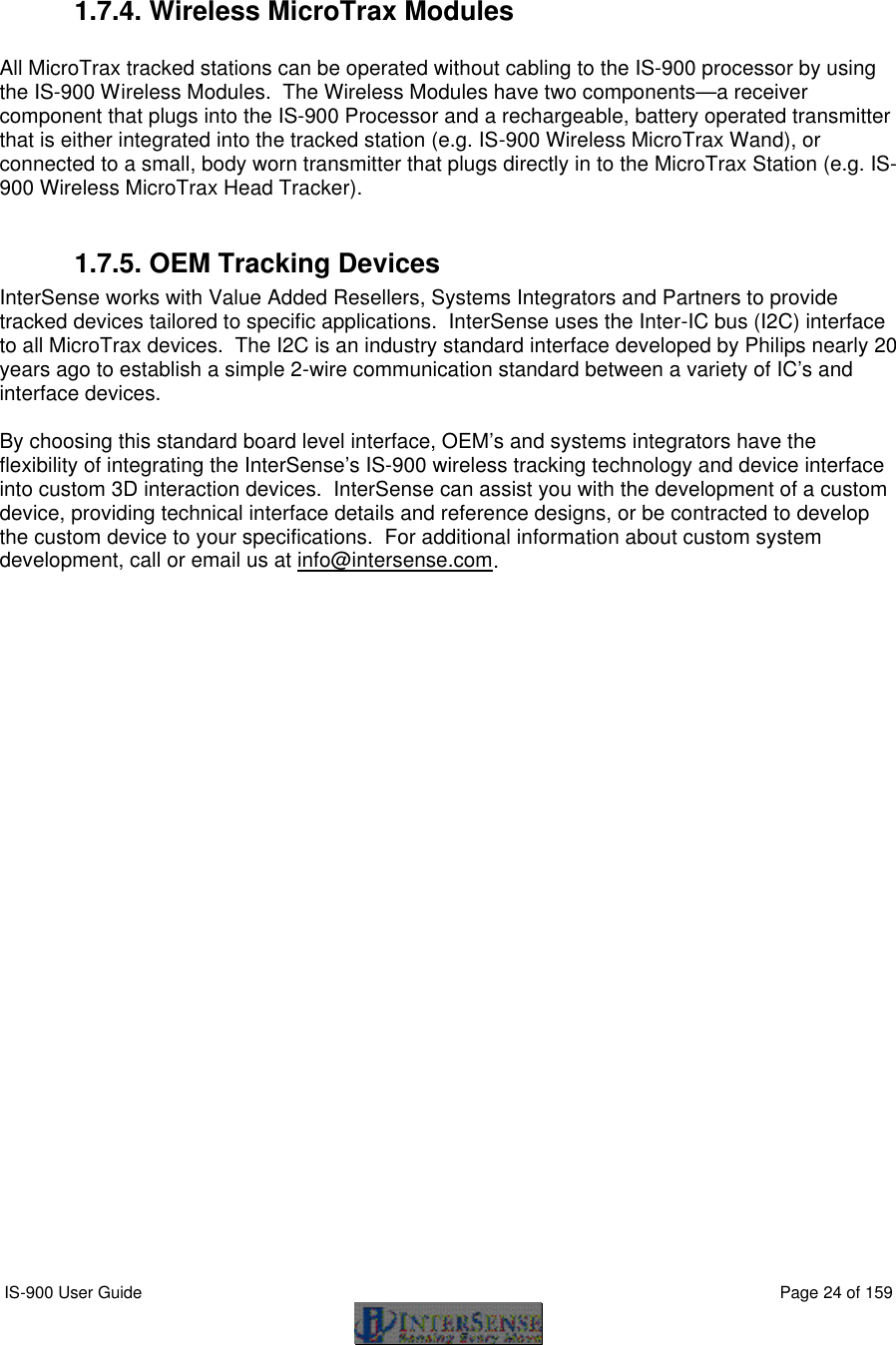
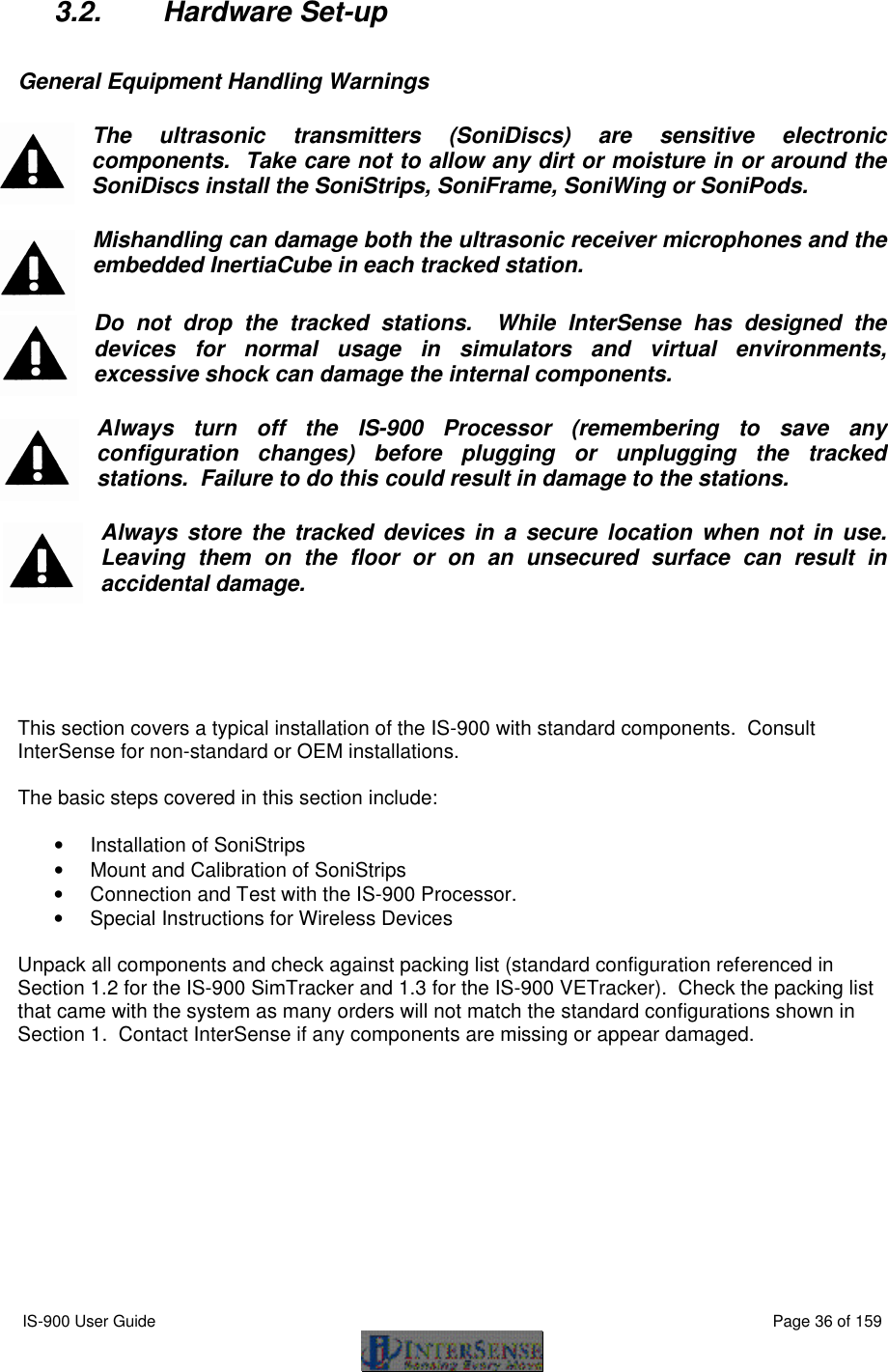
![IS-900 User Guide Page 63 of 159 Boresight B{stationNum}<> (Fastrak compatibility mode) MB{stationNum}<> (Firmware Version 2.x compatibility mode) Boresight a station. If boresight reference angles have been specified by the G{stationNum}[yawref, pitchref, rollref]<> command prior to issuing of Boresight command then that orientation becomes the new reference point. The angles output by the tracker at that orientation become zero. Otherwise, system uses current station orientation and that becomes the new reference line of sight. Please make sure that the object being tracked (like an HMD) is leveled and is pointing down the x-axis when boresighting a station. Unboresight b{stationNum} <> (Fastrak compatibility mode) Mb{stationNum}<> (Firmware Version 2.x compatibility mode) Unboresight a station. Reference angles are cleared for the specified station. Heading Boresight B{stationNum}<> (Firmware Version 2.x compatibility mode) MB{stationNum}<> (Fastrak compatibility mode) This command has no effect with the IS-900. Heading Unboresight b{stationNum}<> (Firmware Version 2.x compatibility mode) Mb{stationNum}<> (Fastrak compatibility mode) This command has no effect with the IS-900. Set Serial Communication Parameters o{rate,parity,bits,HHS}<> Change the serial communication parameters rate is one of 3,12,24,48,96,192,384,576,1152 (rate is multiplied by 100) parity N = none O = odd E = even bits 7 or 8 HHS (Hardware handshake) 0 = OFF 1 = ON Default serial communications settings: Baud 1152](https://usermanual.wiki/Thales-Visionix/910EWTX.Manual-Part-1/User-Guide-838165-Page-63.png)
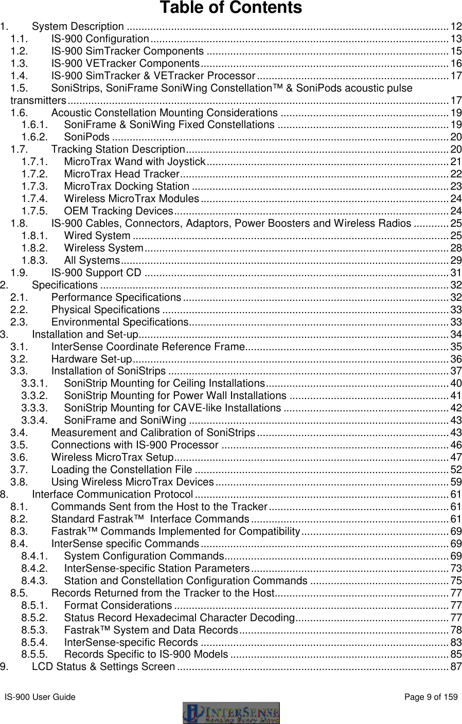
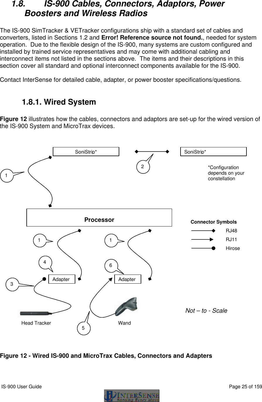
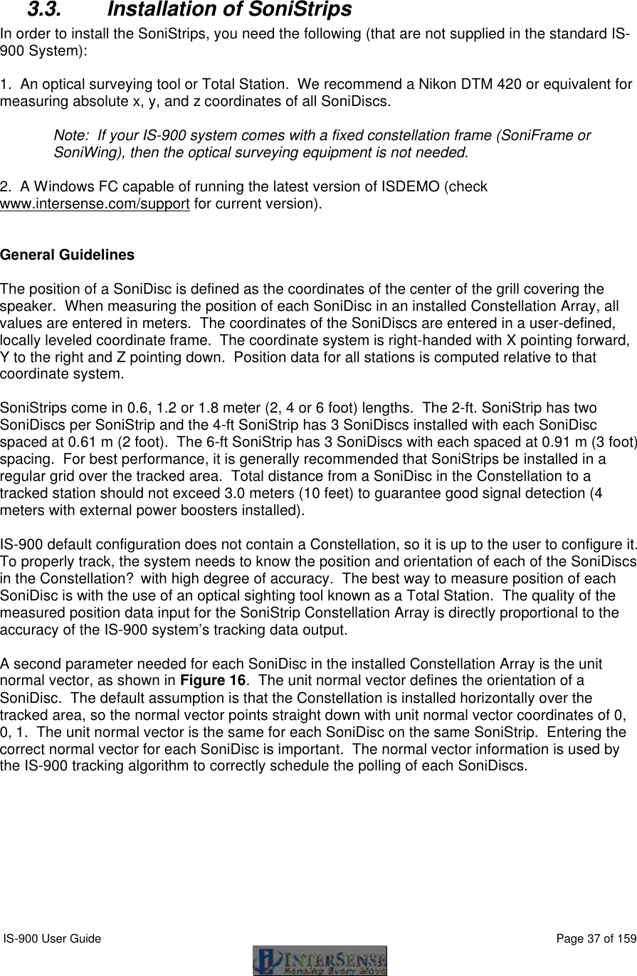
![IS-900 User Guide Page 64 of 159 Parity N bits 8 HHS OFF System Record Request S Request a system status record to be sent. Station Status l{stationNum},[state]<> Set the stationNum on or off. state 0 = OFF, 1 = ON Default All connected stations are on Output Units Control U Sets output data record position units to inches. u Sets the position units to centimeters. These only matter in 6-DOF mode. Default U System control ^K Save the current settings to nonvolatile memory. W Restore the system settings to the factory defaults. ^Y Restart the firmware to the power up condition. ^S Suspend data transmission. ^Q Resume data transmission. Caution: Sending W command will cause all the user configuration information to be lost. Output record mode F Put in ASCII output mode f Put in Binary output mode. Default F](https://usermanual.wiki/Thales-Visionix/910EWTX.Manual-Part-1/User-Guide-838165-Page-64.png)
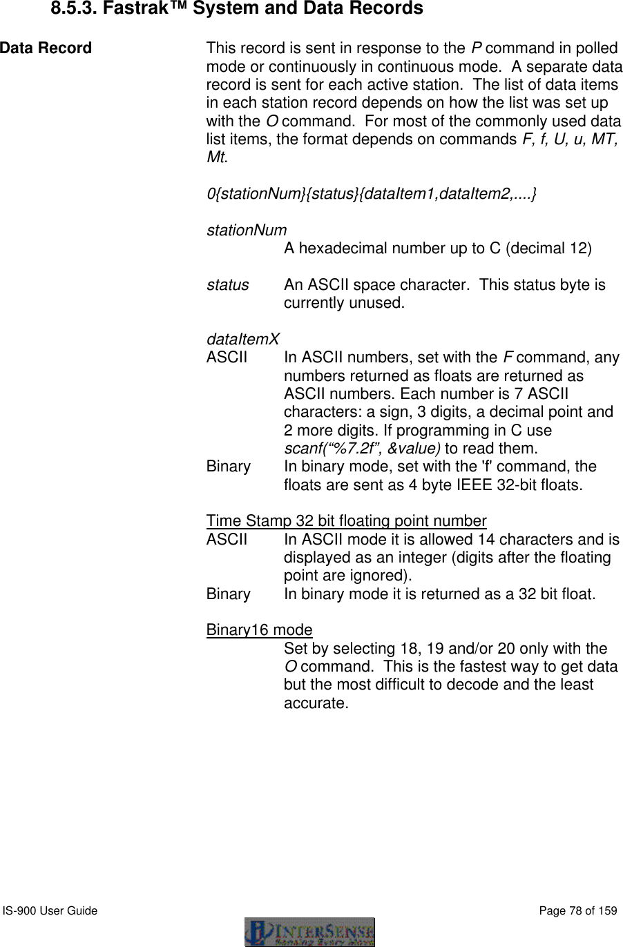
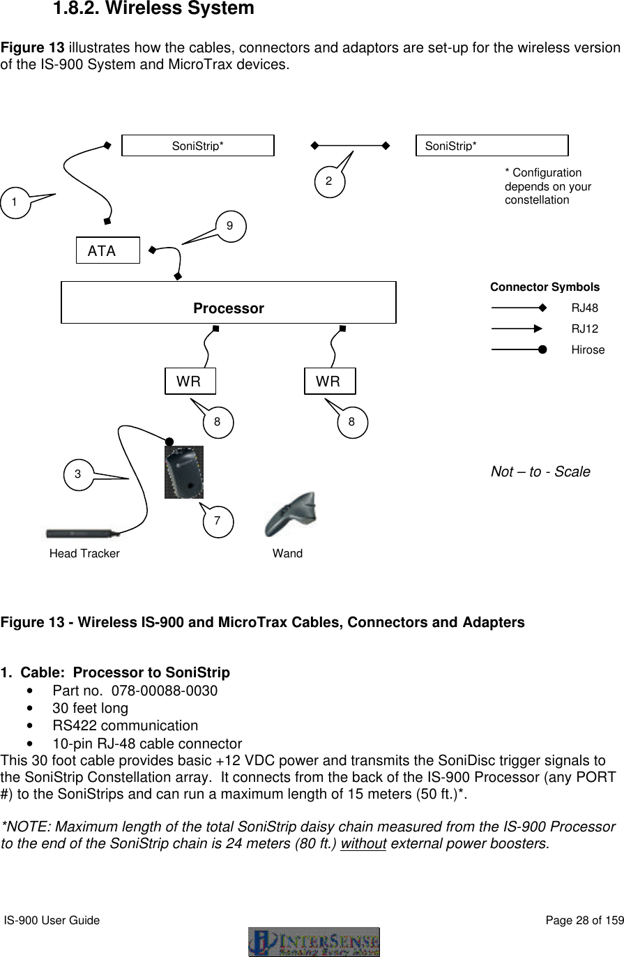
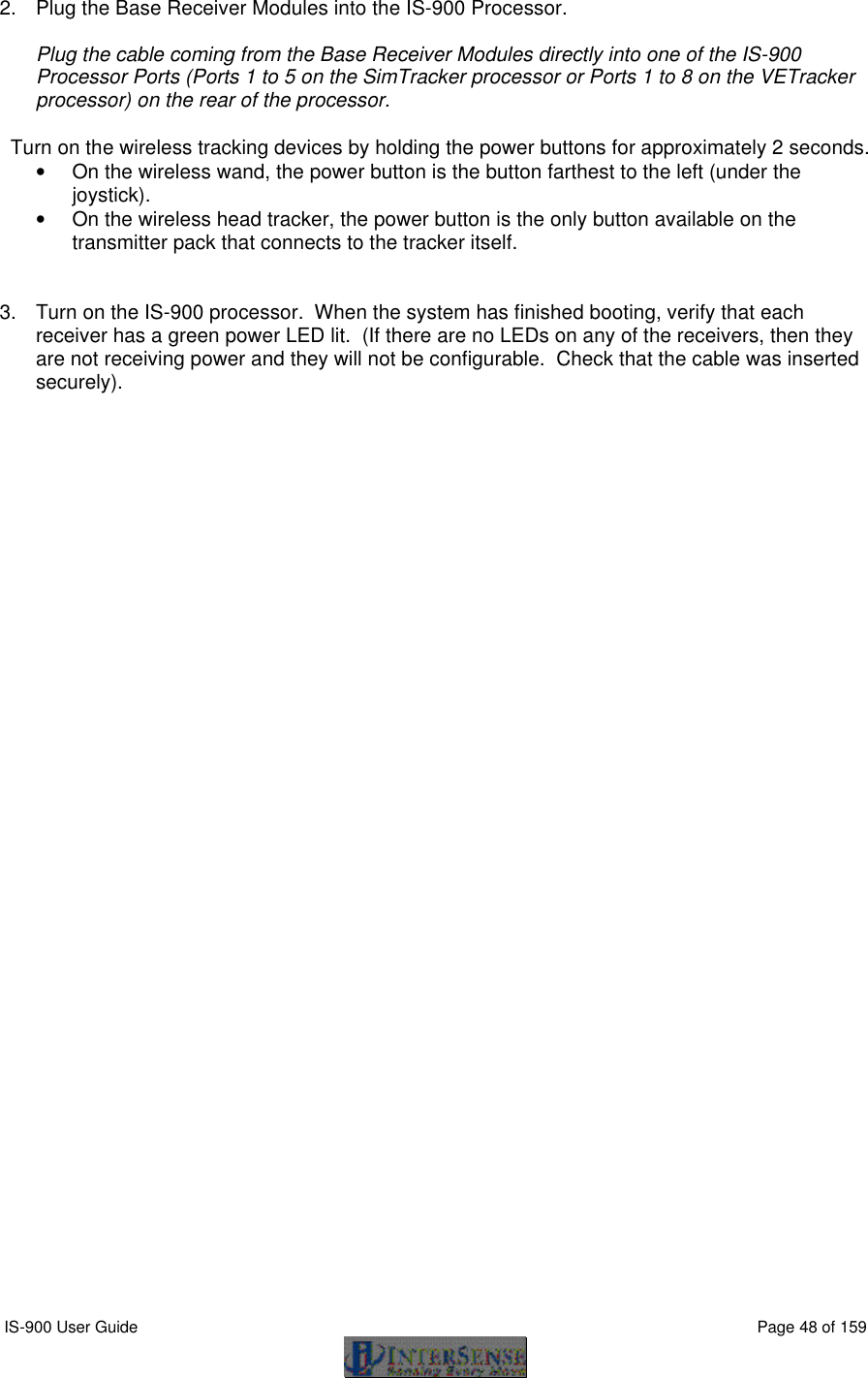
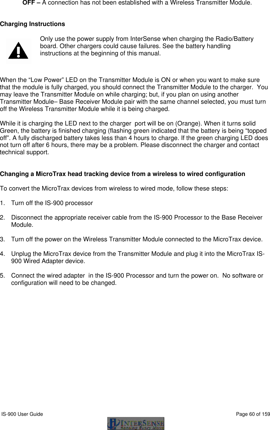
![IS-900 User Guide Page 65 of 159 Output record list settings O{stationNum},[p1],[p2],[p3],.....,[pn]<> Sets the output data list for stationNum. If optional parameters are omitted, a data record containing current output list settings for the station is returned. Item Description Output Format 0 ASCII space character 1 ASCII byte 1 ASCII CR, LF pair 2 ASCII bytes 2 x, y, z position coordinates 3 floats 4 yaw, pitch and roll Euler angles 3 floats 5 X-axis direction cosines 3 floats 6 Y-axis direction cosines 3 floats 7 Z-axis direction cosines 3 floats 11 orientation quaternion 4 floats 16 stylus switch status (always 0) 1 byte (ASCII or binary)18 x, y, z in 16 bit binary format see below 19 yaw, pitch and roll in 16 bit binary format see below 20 quaternion in 16 bit binary format see below 21 time stamp, in selected time units see section 5.3.1 22 buttons see below 23 joystick see below 40 tracking status 0-255 68 – 71 auxiliary inputs 75 communication integrity 0-100 Default 2,4,1 Data Item 4 – Euler Angles. The Euler angles are defined as rotations about Z, then Y, then X in body frame. Angles are returned in degrees Yaw Roll Pitch X Y Z](https://usermanual.wiki/Thales-Visionix/910EWTX.Manual-Part-1/User-Guide-838165-Page-65.png)
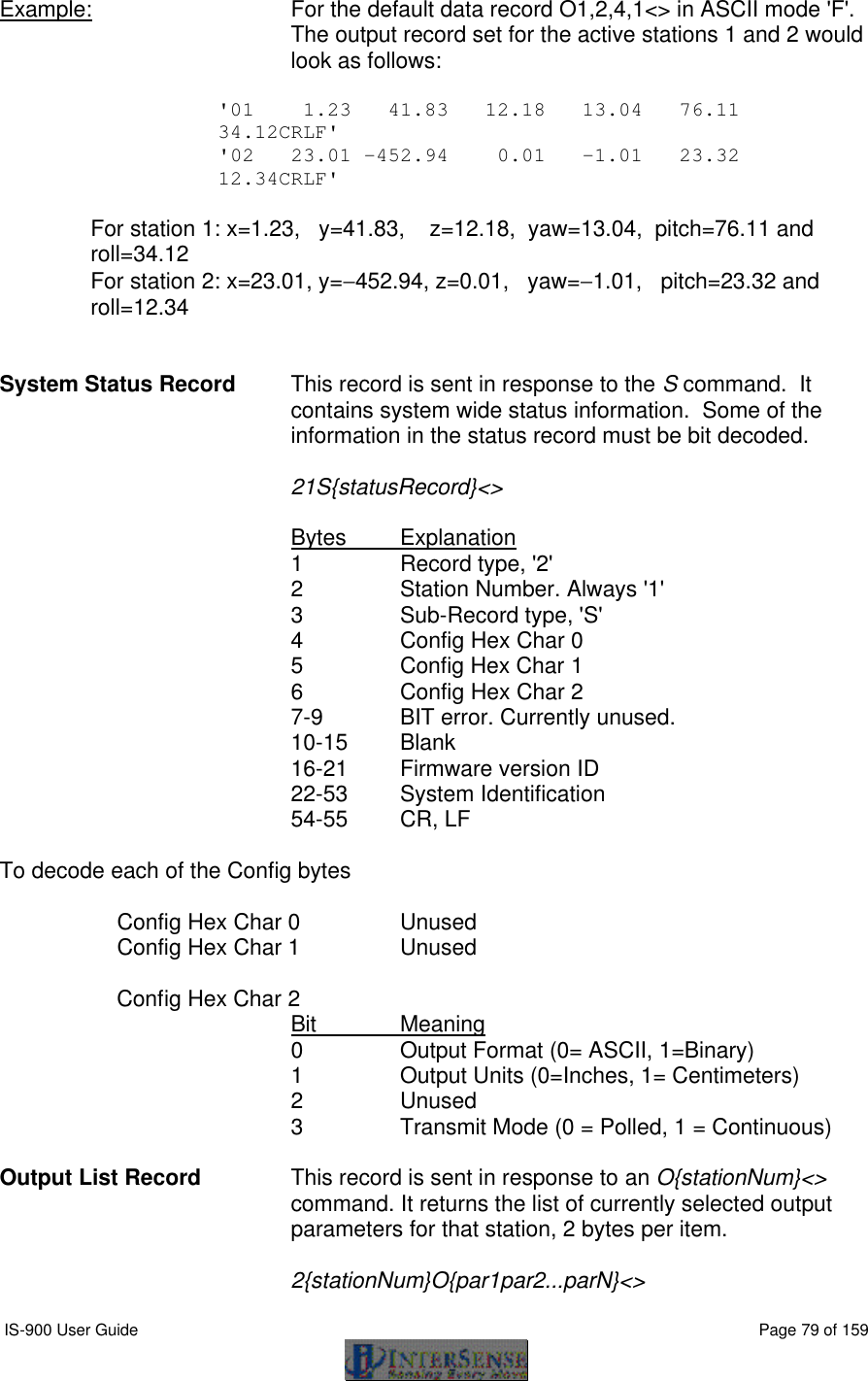
![IS-900 User Guide Page 66 of 159 Data Items 5, 6, 7 – Direction Cosines. X-axis, Y-axis and Z-axis direction cosines can be used to construct a 3x3 rotation matrix. X direction cosines. Y direction cosines. Z direction cosines. This matrix can also be constructed from Euler angles: Data Item 11 – Orientation Quaternion. Quaternion is returned as q = [w, x, y, z]. Quaternion to rotation matrix conversion can be accomplished using the following formula: Data Items 18, 19, 20 – 16 bit binary format. 16 bit binary format can be used in applications requiring fastest possible serial I/O. Each floating point number is stored in 2 bytes with only 14 bits containing actual data. This results in lower accuracy than the standard IEEE floating point format. Data is 2’s-complement. The first byte of the data set has its high-order bit set to 1; all others have them set to zero. This can be used for data synchronization. Data is returned low-order byte, then high-order byte. Use following code sample as an example on how to decode this format: x1 x2 x3 y1 y2 y3 z1 z2 z3 1–2y2 – 2z2 2xy – 2wz 2xz + 2wy 2xy + 2wz 1 – 2x2 – 2z2 2yz – 2wx 2xz – 2wy 2yz + 2wx 1 – 2x2 – 2y2 cos(P)*cos(Y) sin(R)*sin(P)*cos(Y) - cos(R)*sin(Y) cos(R)*sin(P)*cos(Y) + sin(R)*sin(Y) cos(P)*sin(Y) sin(R)*sin(P)*sin(Y) + cos(R)*cos(Y) cos(R)*sin(P)*sin(Y) - sin(R)*cos(Y) -sin(P) cos(P)*sin(R) cos(P)*cos(R)](https://usermanual.wiki/Thales-Visionix/910EWTX.Manual-Part-1/User-Guide-838165-Page-66.png)
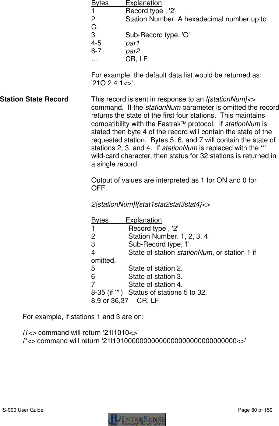
![IS-900 User Guide Page 67 of 159 To decode position: lo = (dataRecord[3] & 0x007F); hi = (dataRecord[4] & 0x007F); int14bit = (lo « 2) | (hi « 9); result = (float) int14bit * 3.0 / 32768.0; Result is a number representing position (in meters) and has a full range of ± 3.0 meters (−300.0 to+299.963 centimeters or –118.110 to 118.096 inches). To decode Euler angles: lo = (dataRecord[3] & 0x007F); hi = (dataRecord[4] & 0x007F); int14bit = (lo « 2) | (hi « 9); result = (float) int14bit * 180.0 / 32768.0; Resulting number represents orientation and has a full range of ± 180.0 (−180.0 to +179.978) degrees. To decode Orientation Quaternion: lo = (dataRecord[3] & 0x007F); hi = (dataRecord[4] & 0x007F); int14bit = (lo « 2) | (hi « 9); result = (float) int14bit * 1.0 / 32768.0; Resulting quaternion value has range of ± 1.0. Data Item 22 – Buttons. One 3-digit integer in ASCII format or one byte in binary format. Bits represent the button states of a station’s buttons. If a button is pressed, the corresponding bit is 1 otherwise it is 0. The bit assignments for the wand are (where bit 0 is the least significant bit): Bit Button MicroTrax Wand button 0 1 1 on wand image 1 2 2 on wand image 2 3 3 on wand image 3 4 4 on wand image 4 5 center (press joystick) 5 6 trigger](https://usermanual.wiki/Thales-Visionix/910EWTX.Manual-Part-1/User-Guide-838165-Page-67.png)
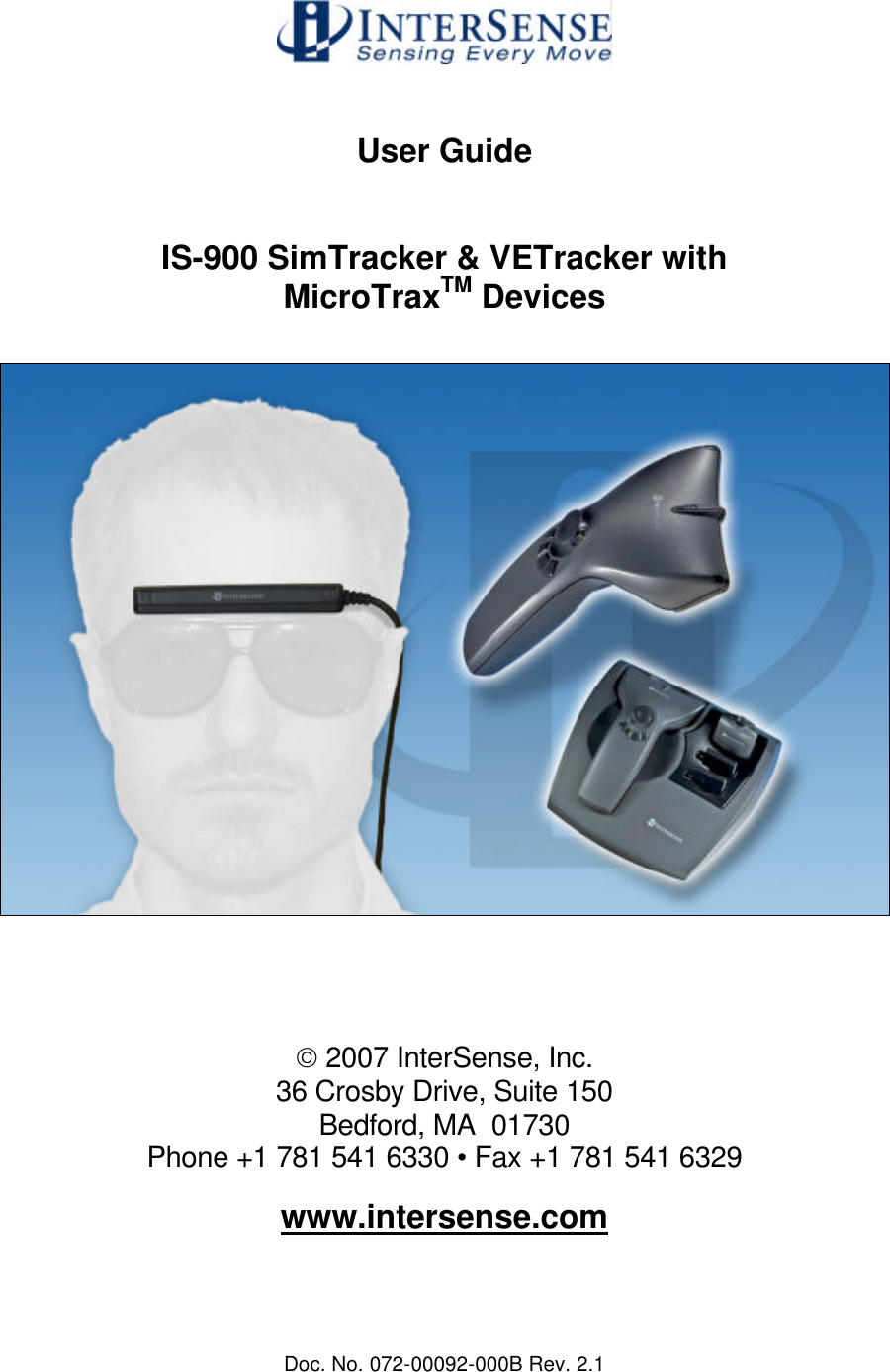
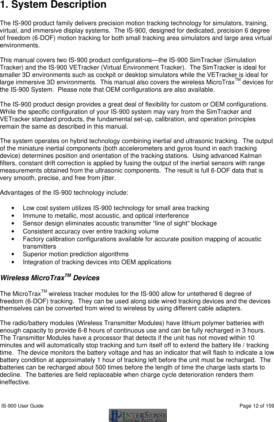
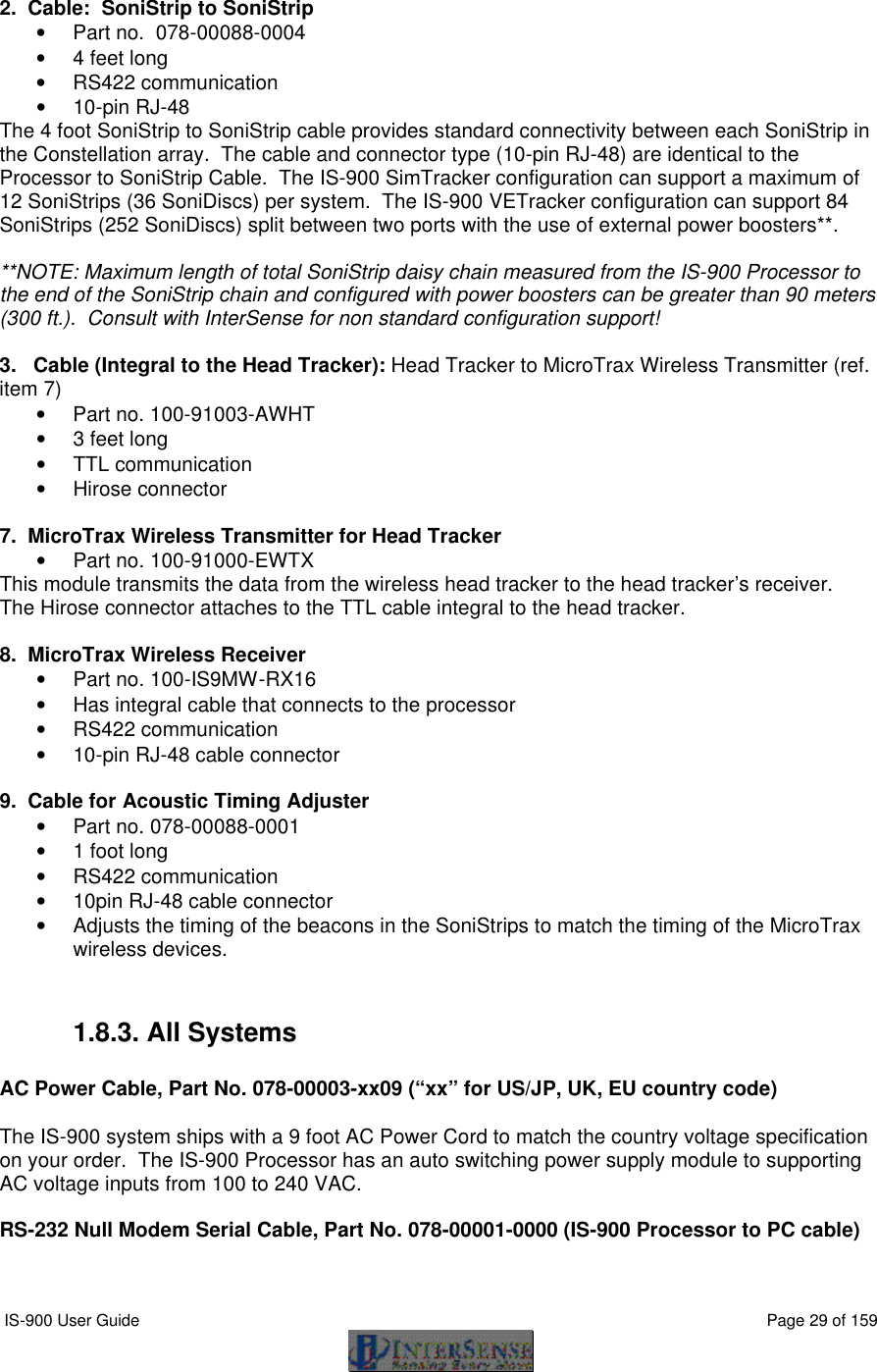
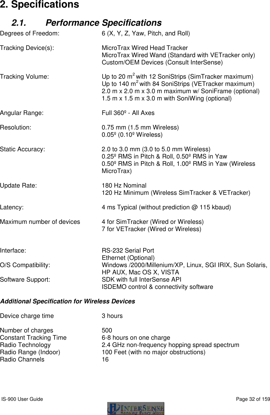
![IS-900 User Guide Page 68 of 159 Data Item 23 – Joystick. Two integers, one for each axis, values ranging from 0 to 255. Two 3-digit integers in ASCII format or two 1-byte unsigned values in binary format. Values at limits and at center are: Axis Position Value left/right (1st integer) left 0 center 127 right 255 front/rear (2nd integer) rear 0 center 127 front 255 Define Tip Offsets N{stationNum},[Ox, Oy, Oz]<> By default, the point being tracked is for each station is: Wand Station: Tip. Head Tracking Station: Intersection of front surface, bottom surface and at mid length, see image to the left. This command allows the user to define a set of position offsets, so a different point can be tracked. Offsets are measured in the body coordinate frame of the MicroTrax station and are entered in centimeters. If optional parameters are omitted, current settings are returned. Default 0,0,0 Position Operational Envelope V{stationNum},[Xmax, Ymax, Zmax, Xmin, Ymin, Zmin]<> This command sets the boundaries of the area where position is to be tracked. Whenever a station leaves the defined range, position tracking is stopped and only resumed once it is back within the defined boundaries. Parameters are entered in meters. If optional parameters are omitted, current settings are returned. Units are meters. Default 200,200,200,-200,-200,-200 Tip Offset: intersection of front surface and bottom surface and at mid length.](https://usermanual.wiki/Thales-Visionix/910EWTX.Manual-Part-1/User-Guide-838165-Page-68.png)
![IS-900 User Guide Page 69 of 159 8.3. Fastrak™ Commands Implemented for Compatibility Hemisphere H{stationNum},[p1,p2,p3]<> Sets the tracking hemisphere for a magnetic tracking system. Because InterSense trackers are not magnetic the parameters are ignored. However, they can be set and then queried for compatibility with software such as MultiGen SmartScene or Immersion Corporation haptic Software. If optional parameters are omitted, a data record containing current Hemisphere settings for the station is returned. Default 1,0,0 8.4. InterSense specific Commands All InterSense specific commands start with the letter M (for “Manufacturer-specific”) and must be completed by a CR,LF pair. 8.4.1. System Configuration Commands Time Units The time stamp recorded is the time when the tracker data was collected from the hardware. The time index is set to zero when tracker is first turned on. MT<> Sets the units for the data record time stamp to milliseconds. Mt<> Sets the units for the data record time stamp to microseconds. Default T Set Current Time to Zero MZ<> This command sets current time index of the tracker to zero.](https://usermanual.wiki/Thales-Visionix/910EWTX.Manual-Part-1/User-Guide-838165-Page-69.png)
![IS-900 User Guide Page 70 of 159 Set Ethernet Communication Parameters MEthIp[address]<> Sets System IP address. Use dotted format like 192.168.1.1. If address is omitted, the current address is returned, 31EI[address]<>. The IP address takes effect immediately unless an address was already set, in which case system settings must be saved and the system must be restarted. MEthUdp[state]<> Sets state of UDP broadcast. state=1 to enable, state=2 to disable (default). MEthUdpPort[port]<> Sets UDP broadcast port. Default Ethernet communications settings: UDP state OFF UDP port 5001 IP address None InterSense System Status Record Request MS<> Request the manufacturer-specific system status record. This is information about parameters which are specific to the InterSense product, additional to the standard system status information obtained using the S command. Tracking Status Record Request MP<> Requests tracking status information for all 12 stations. See Section 5.5.5 for the description. Ultrasonic Timeout Interval MU[interval]<> This command has no effect with the IS-900. Default N/A Ultrasonic Receiver Sensitivity Mg[Level]<> This command has no effect with the IS-900. Default N/A](https://usermanual.wiki/Thales-Visionix/910EWTX.Manual-Part-1/User-Guide-838165-Page-70.png)
![IS-900 User Guide Page 71 of 159 Genlock Synchronization MG[State, Rate]<> State 0 – Genlock is off 1 – Reserved 2 – External sync, manual (supply strobe rate) 3 – Internal sync, supply output record rate Rate Value in Hertz used with State = 2 and 3 Default 0 Genlock Phase MGP[Param]<> Param can be the Phase (0 to 100%) or ‘+’ to increase to the next phase point, or ‘-‘ to decrease to the next phase point. Please see Appendix F for complete details. Default 0 Genlock Sync Source MGS[source]<> source 1 – TTL 2 – NTSC Configuration Lock Configuration lock commands are used to prevent unintentional changes to tracker configuration. Two Levels of protection are provided. The First prevents changes to saved settings. The second prevents changes to current unsaved (session) settings as well as saved settings. MConfigLockMode[mode]<> Mode 0 Lock off 1 Lock saved settings 2 Lock saved and session settings Default 0 In mode 1 (lock saved settings), the Fastrak commands to save current (^K) and restore factory (W) settings are disabled. In mode 2 (lock saved and session settings), the Fastrak command to restore saved settings (^Y) is disabled as well as ^K and W. In mode 0 (lock off), ^Y, ^K and W are all enabled. When mode is changed, it is saved to nonvolatile memory without affecting any other saved settings. If mode is omitted, the current setting is returned. The LCD menu options to save and restore settings are not affected by lock mode.](https://usermanual.wiki/Thales-Visionix/910EWTX.Manual-Part-1/User-Guide-838165-Page-71.png)
![IS-900 User Guide Page 72 of 159 SoniStrip LED control ML[state]<> If state is 0, the blue LEDs on the SoniStrips are disabled. Visual confirmation of the operation of the ultrasonic system is important, so don’t disable the LEDs unless they interfere with your application. Default 1 Beacon Scheduler MSchAlg[n]<> Selects beacon Scheduling Algorithm. If n is 1, a distance-based algorithm is used. This algorithm chooses beacons based on distance only. If n is 2 a directional algorithm is used which chooses beacons based on orientation as well as distance. Default 2 Error reporting Hardware and configuration errors are stored internally and can be reported to the application. If the application is not setup to accept error messages, or if you are not sure, error reporting should be disabled. This setting is not saved with tracker configuration, so error reporting is off every time tracker is turned on. ME<> Returns all errors, one per error message. MEC<> Clear all errors from internal list. ME1<> Enable error reporting. ME0<> Disable error reporting. Default Error reporting is OFF Command logging Command logging captures all host commands into a file for debugging purposes. The log file holds a maximum of 500 kB. When the max size is reached, the file is rewound and overwritten with new entries. Long series of P and MP commands are abbreviated to save space. The command logging state is also indicated on the LCD (see Section 9). Command logging control is available on the LCD menu under System ConfigàCommand Log: Enable Log, Disable Log and Clear Log. It is accessed by the following command set. MLogOpen<> Enables logging. If settings are saved, logging will remain on through reset. An existing log file is always appended to. MLogClose<> Disables logging. MLogClear<> Disables logging and deletes log file. Use MLogOpen to resume logging.](https://usermanual.wiki/Thales-Visionix/910EWTX.Manual-Part-1/User-Guide-838165-Page-72.png)
![IS-900 User Guide Page 73 of 159 MLogState<> Returns logging state (0=off, 1=on), 31LS{0,1}<> MLogSend<> Outputs log file to host one command per line. 31LF<timestamp in ms>:<command><> the timestamp is a decimal number and is not zero-padded. The log file can alternatively be retrieved using ISDEMO (see section 14). 8.4.2. InterSense-specific Station Parameters InterSense Station Status Record Request Ms{stationNum}<> Request an individual sensor status record for stationNum. This is information about parameters which are specific to the InterSense product. Prediction Interval Mp{stationNum},[Interval]<> Sets the time-interval of prediction for stationNum. Interval is an integer number of time in milliseconds. Suggested range is 0-50 ms. This parameter is used for both position and orientation prediction. If optional parameter is omitted, current prediction value is returned. Default 0 Perceptual Enhancement Level MF{stationNum},{Mode}<> In order to provide the best performance for a large range of various applications, 3 levels of perceptual enhancement are available. None of the modes introduces any additional latency. Mode 0 provides the best accuracy. The drift correction adjustments are made immediately; no jitter reduction algorithms are used. This results in somewhat jumpy output (not recommended for head-tracking) but with lower RMS error. Use this mode for accuracy testing or for any application that requires best accuracy. Mode 1 provides accuracy similar to that of mode 0, with an addition of a jitter reduction algorithm. This algorithm reduces the accuracy by only a small amount and does not add any latency to the measurements.](https://usermanual.wiki/Thales-Visionix/910EWTX.Manual-Part-1/User-Guide-838165-Page-73.png)
![IS-900 User Guide Page 74 of 159 Mode 2 is recommended for use with HMD or other immersive applications. The drift correction adjustments are made smoothly and only while the sensor is moving, so as to be transparent to the user. Default 2 Compass Heading Correction MH{stationNum, mode}<> Turns on the stationNum’s compass heading correction. To operate effectively, the magnetic field in the environment needs to be homogeneous. Only valid when an InertiaCube is being used as a station (i.e. not valid for MicroTrax devices). For an InertiaCube, the modes are defined: Mode 0 - Compass is OFF, no heading compensation is applied. Not recommended, Modes 1 or 2 are preferred. Mode 1 - Partial compass mode. Magnetometer readings are used to reduce drift and maintain stability, but not as an absolute measurement system. In this mode, system is much less susceptible to magnetic interference, but heading drift will slowly accumulate. This mode is particularly useful when high rotational sensitivity settings are used. Mode 2 - FULL compass mode. Readings produced by the magnetometers inside the InertiaCube are used as the absolute reference orientation for yaw. Default 2 Mh{stationNum}<> Turns off the stationNum’s compass heading correction. There can be slow drift in the yaw direction. Only valid when an InertiaCube is being used as a station (i.e. not valid for MicroTrax devices). Rotational Sensitivity Level MQ{stationNum},[Sensitivity Level]<> Adjusts rotational sensitivity of a station when the Perceptual Enhancement Level is set to level 2. Sensitivity Level is an integer 1 to 4 where 1 is the lowest and 4 is the highest sensitivity. It is recommended that sensitivity be set to 4 when enhancement is set to level 1. If optional parameter is omitted, current value is returned. Default 3](https://usermanual.wiki/Thales-Visionix/910EWTX.Manual-Part-1/User-Guide-838165-Page-74.png)
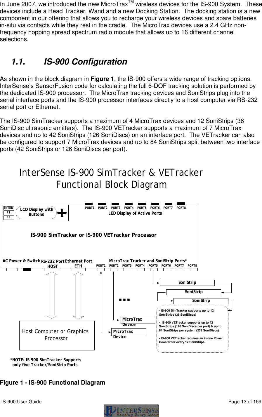
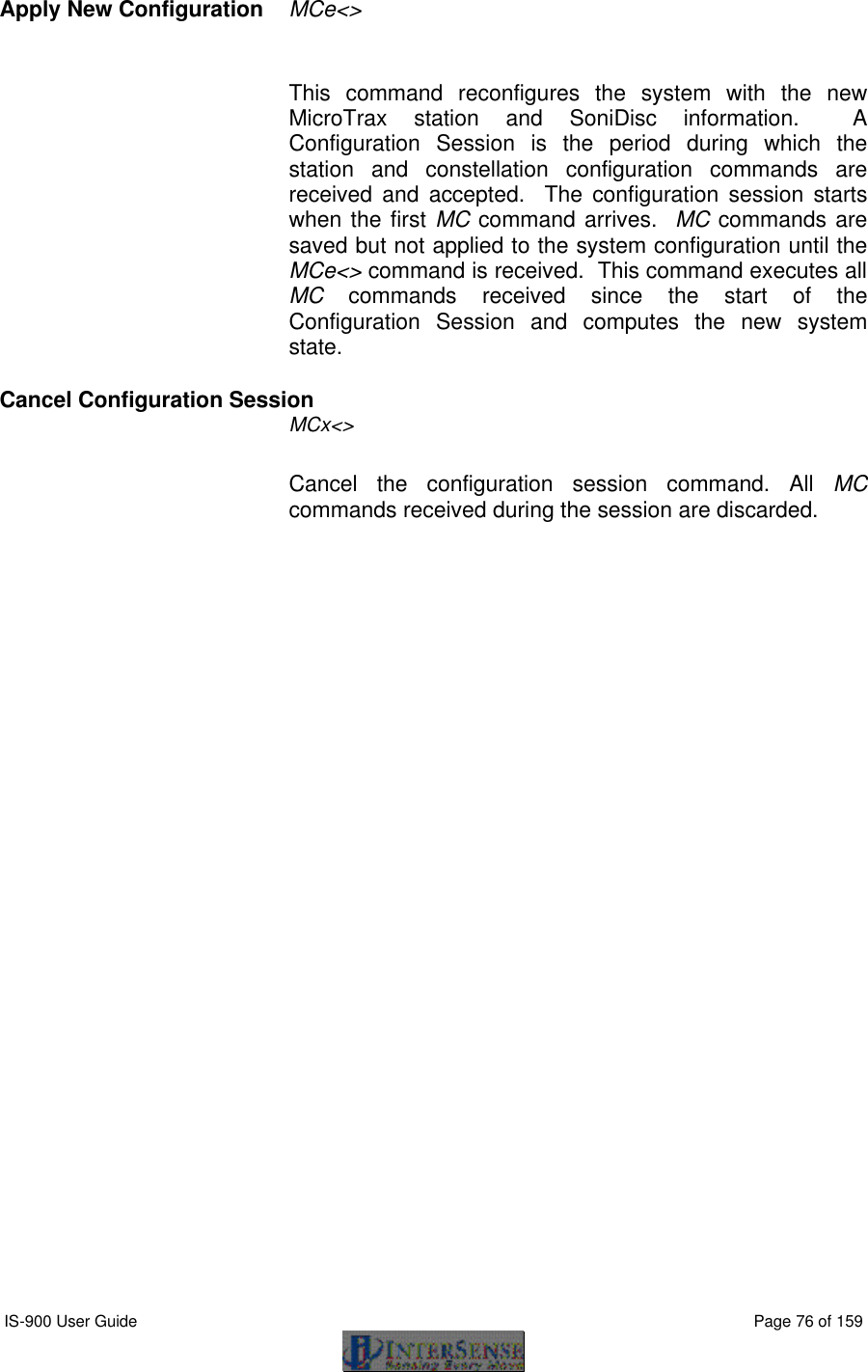
![IS-900 User Guide Page 75 of 159 8.4.3. Station and Constellation Configuration Commands This section describes the commands used to assign sensing devices to the logical components of the tracking system. Such devices with the IS-900 are SoniStrips and the SoniDiscs (beacons) that make up the Constellation Array. All commands in this section start with MC. A Configuration Session is the period during which MC commands are received and accepted. It starts when the first MC command arrives and ends when these commands are explicitly activated with the MCe<> (or discarded with the MCx<>) command. Associate Fixed PSE with a Constellation MCF[FPSE number],[xp, yp, zp, xn, yn, zn, IDcode]<> Configures or adds a Fixed PSE. For IS-900 FPSE is a SoniDisc ultrasonic transponder beacon. If only the FPSE number parameter is present then current data for that PSE is returned on the serial port. If that PSE is not configured, record will contain Hardware ID of -1. If no parameters are provided then data for all configured Fixed PSEs is returned, each PSE in a separate record. This command does not take effect until explicitly activated by the MCe<> command. FPSE number A Unique number identifying a Fixed PSE (beacon) within a Constellation (a complete set of fixed PSEs). Numbering starts at 1. xp, yp, zp FPSE position in meters. xn, yn, zn Normal vector. IDcode Hardware ID of the PSE. <> CR LF pair. Disassociate Fixed PSE from the Constellation MCf[Fixed PSE number, IDcode]<> If PSE number and IDcode are not associated in the current configuration, this command is ignored. This command does not take effect until explicitly activated by the MCe<> command. Clear All Fixed PSEs (Constellation) Command MCC<> Delete all Fixed PSEs from the configuration. This command does not take effect until explicitly activated by the MCe<> command.](https://usermanual.wiki/Thales-Visionix/910EWTX.Manual-Part-1/User-Guide-838165-Page-75.png)
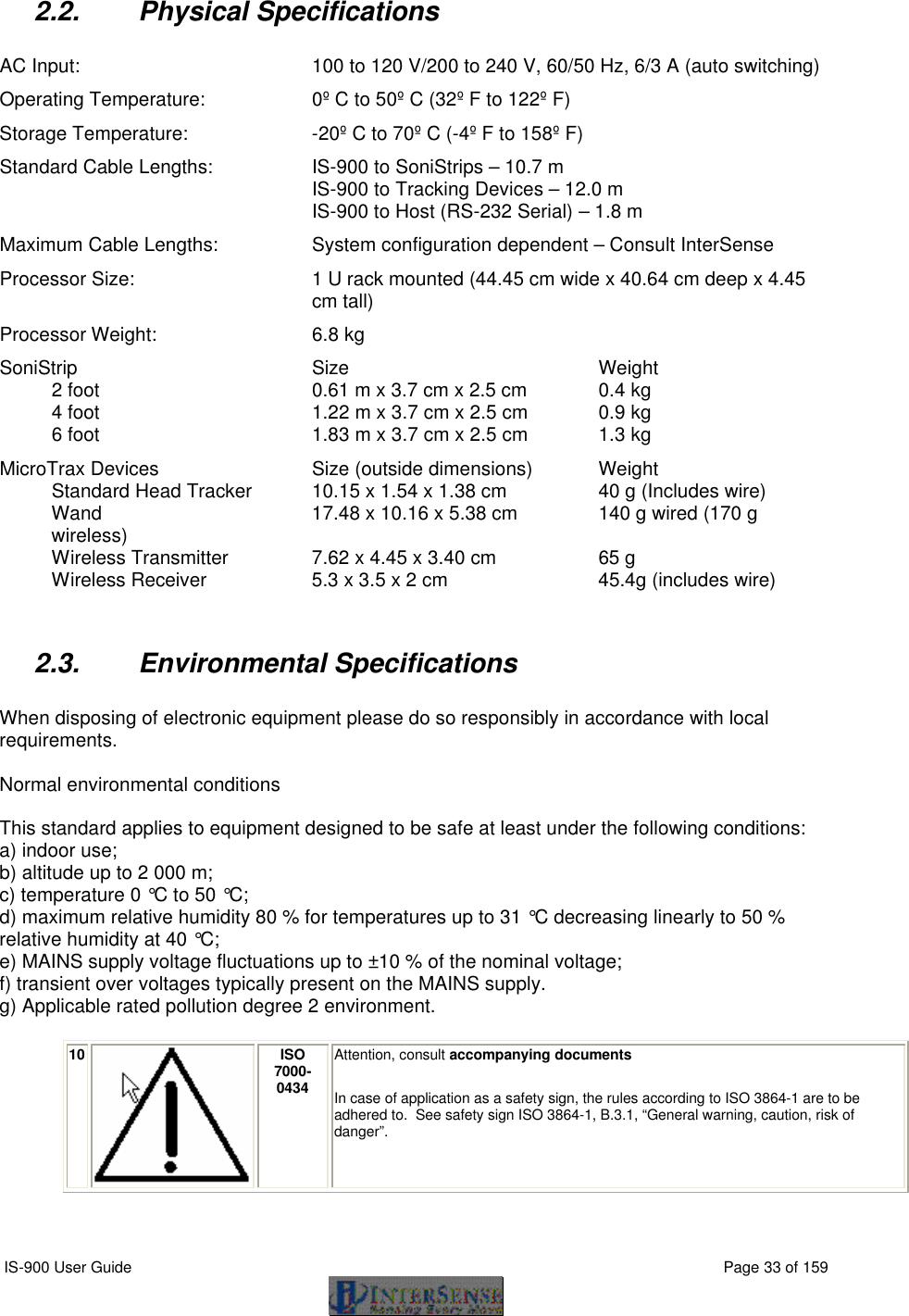
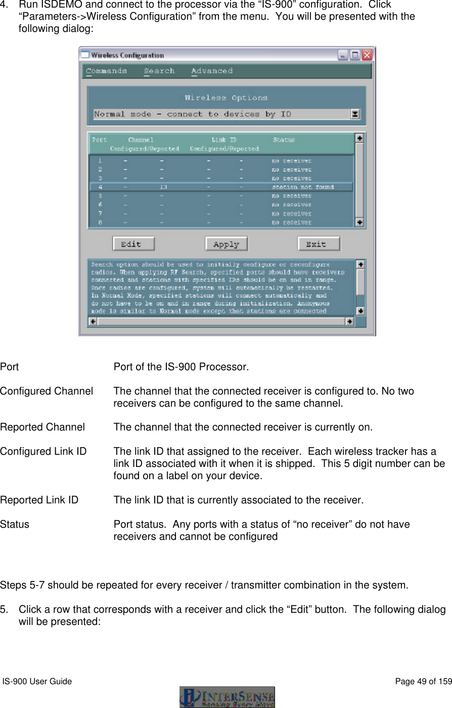
![IS-900 User Guide Page 77 of 159 8.5. Records Returned from the Tracker to the Host 8.5.1. Format Considerations Record Headers The first byte of each record is used to identify its type. 0 – Data record. 2 – Fastrak™ status record. 3 – InterSense manufacturer-specific status record. Floating Point Numbers Floating point numbers can be returned as IEEE 32 bit floats or as ASCII numbers in X.xf notation, where: X is the total number of characters used to represent the float. x is the number of digits after the floating point. f is a symbol indicating that number is a float. For example, number -42.6 in 10.4f format would look as follows: “-42.6000” 8.5.2. Status Record Hexadecimal Character Decoding System Status, Manufacturer Status, and Manufacturer Station records use Hexadecimal Characters to encode status data. Each character can be 0 to F and can encode 4 bits. Logical AND operator can be used to test specific bits. Please see following code example: unsigned short byte1, byte2, byte3; char hexChar[2]; hexChar[1] = 0x00; hexChar[0] = statusRecordBuffer[3]; sscanf(hexChar,"%x", &byte1); hexChar[0] = statusRecordBuffer[4]; sscanf(hexChar,"%x", &byte2); hexChar[0] = statusRecordBuffer[5]; sscanf(hexChar,"%x", &byte3);](https://usermanual.wiki/Thales-Visionix/910EWTX.Manual-Part-1/User-Guide-838165-Page-77.png)