Thales Visionix IC3RX16 Wireless InertiaCube3 Receiver User Manual WirelessIC3Manual
Thales Visionix, Inc. Wireless InertiaCube3 Receiver WirelessIC3Manual
Users Manual
Wireless InertiaCube3 Supplemental Manual 1
Doc. No. 072-00096-0E05
Wireless InertiaCube3™
Wireless InertiaCube3 and Receiver
Supplemental Product Manual for use with
Wireless InertiaCube3 Serial and USB Interfaces
2005 InterSense, Inc.
36 Crosby Drive
Bedford, MA 01730
Phone 781 541 6330 • Fax 781 541 6329
www.intersense.com

Wireless InertiaCube3 Supplemental Manual 2
Doc. No. 072-00096-0E05
Supplemental User Manual for InertiaCube3
Library Version 3.8x and higher
This supplemental user’s manual for the Wireless InertiaCube3 covers the set up and use of
the wireless sub-system integrated with the InertiaCube3. Please refer to the “Product Manual
for use with InertiCube3 and the InertiaCube3 Processor”(InterSense Document No. 072-
00094-0D05) for information about the set-up and operation of the InertiaCube3. This
document is referenced herein at the InertiaCube3 Manual.
Contacting InterSense
Please do not hesitate to contact us for any reason. We are here to help and we value your
business.
InterSense Inc.
36 Crosby Drive, Suite 150
Bedford, Massachusetts 01730
USA
Telephone: (781) 541 6330 email: info@intersense.com
Fax: (781) 541 6329 Internet: www.intersense.com
Technical Support: (781) 541 7624 email: techsupport@intersense.com
Patents
The label below identifies the protection granted by the Government of the United States to
InterSense for its products:
U.S. Patents
5645077, 5807284, 5953683,
6162191, 6176837, 6314055,
6361507, 6409687, 6424410,
6456567, 6474159, 6500008,
6529331 and Patents Pending
INTERSENSE

Wireless InertiaCube3 Supplemental Manual 3
Doc. No. 072-00096-0E05
Trademarks
InterSense™, InertiaCube™, InertiaCube3
TM SoniDisc™, GEOS™, PULSAR™,
CONSTELLATION™ are trademarks of InterSense Inc. All other trademarks are the property of
their respective owners.
Copyright 2005
InterSense, Inc.
Regulatory Statements and Approvals
FCC Statements:
This device complies with part 15 of the FCC Rules. Operation is subject to the following two
conditions:
(1) This device may not cause harmful interference, and
(2) This device must accept any interference received, including interference that may cause
undesired operation.
Caution: changes or modifications not expressly approved by the party responsible for
compliance could void the user’s authority to operate the equipment.
NOTE: This equipment has been tested and found to comply with the limits for a Class
B digital device, pursuant to part 15 of the FCC Rules. These limits are designed to provide
reasonable protection against harmful interference in a residential installation. This equipment
generates, uses and can radiate radio frequency energy and, if not installed and used in
accordance with the instructions, may cause harmful interference to radio communications.
However, there is no guarantee that interference will not occur in a particular installation. If this
equipment does cause harmful interference to radio or television reception, which can be
determined by turning the equipment off and on, the user is encouraged to try to correct the
interference by one or more of the following measures:
—Reorient or relocate the receiving antenna.
—Increase the separation between the equipment and receiver.
—Connect the equipment into an outlet on a circuit different from that to which the receiver is
connected.
—Consult the dealer or an experienced radio/TV technician for help.
Canada - Industry Canada (IC)
This Class B digital apparatus meets all requirements of the Canadian Interference-Causing Equipment Regulations.
cet appareil de la class B respecte toutes les exigences du Reglement sur le matereil brouiller du Canada.
Wireless InertiaCube3 Supplemental Manual 4
Doc. No. 072-00096-0E05
Europe - European Union Notice
All products with the CE marking comply with the EMC Directive (89/336/EEC) and the Low Voltage Directive
(73/23/EEC) issued by the Commission of the European Community.
Compliance with these directives implies conformity to the following European Norms (in brackets are the equivalent
international standards).
• EN 55022 (CISPR 22) - Electromagnetic Interference
• EN 55024 (IEC61000-4-2,3,4,5,6,8,11) - Electromagnetic Immunity
• EN 61000-3-2 (IEC610000-3-2) - Power Line Harmonics
• EN 61000-3-3 (IEC610000-3-3) - Power Line Flicker
• EN 60950 (IEC60950) - Product Safety
Products labeled with the CExxxx or the CE alert marking contain a radio transmitter that complies with the
R&TTE Directive (1999/5/EC) issued by the Commission of the European Community.
Compliance with this directive implies conformity to the following European Norms (in brackets are the
equivalent international standards).
• EN 60950 (IEC60950) - Product Safety
• EN 300 328 Technical requirements for radio equipment.
• ETS 300 893 and ETS 301 489-17 General EMC requirements for radio equipment.
• ETS 301489-1
To determine the type of transmitter, check the identification label on your Product.
Precautionary Statements
Any changes or modifications to the InertiaCube3 not expressly approved by
InterSense will void the warranty and any regulatory compliance issued for the
system.
Do not drop or otherwise shock the tracking devices for they can be
permanently damaged.
Do not bend, twist, pull strongly or tamper in any way with any part of the
cabling.
Take care to avoid electric shocks. Do not plug-in or unplug the power cable
with wet hands.
Do not mount InertiaCube3 with steel or other ferrous metal fasteners and do
not use a magnetic tipped or ferrous metal screwdriver when mounting the
InertiaCube3. Use only non-ferrous fasteners and tools around the
InertiaCube3. FAILURE TO FOLLOW THIS PROCEDURE WILL VOID
WARRANTY AND MAY REQUIRE FACTORY RECALABRATION OF
SENSOR.

Wireless InertiaCube3 Supplemental Manual 5
Doc. No. 072-00096-0E05
TABLE OF CONTENTS
1 SYSTEM DESCRIPTION...................................................................................... 6
1.1 WIRELESS INERTIACUBE3 OPERATION.................................................................. 6
1.2 INERTIACUBE3 COMPONENTS...............................................................................8
2 SPECIFICATIONS AND PERFORMANCE CHARACTERISTICS ................ 9
2.1 WIRELESS INERTIACUBE3 SPECIFICATIONS...........................................................9
3 WIRELESS INERTIACUBE3 SUPPORT SOFTWARE .................................. 10
4 WIRELESS CONFIGURATION WITH DEVICETOOL................................. 11
4.1 FINDING ALL WIRELESS INERTIACUBE3 DEVICES ............................................... 11
4.2 CHANGING RECEIVER CHANNELS ....................................................................... 16
4.3 ATTACH WIRELESS INERTIACUBE3TO WIRELESS RECEIVER............................... 18
4.4 TESTING THE WIRELESS LINK OF INERTIACUBE3 DEVICES.................................. 20
5 WIRELESS INERTIACUBE3 POWER REQUIREMENTS (BATTERY) ..... 22
6 INERTIACUBE3 MOUNTING RECOMMENDATIONS................................ 22
7 DYNAMIC MAGNETIC CALIBRATION......................................................... 23

Wireless InertiaCube3 Supplemental Manual 6
Doc. No. 072-00096-0E05
1 System Description
Congratulations for buying the smallest, precision orientation tracker on the market! This
technology offers you several advantages:
Very low latency
Wireless range up to 100 feet (30 meters)
Smooth, jitter-free tracking
Low power consumption
The Wireless InertiaCube3 is an inertial 3-DOF (Degree of Freedom) orientation tracking system.
It obtains its motion sensing using a miniature solid-state inertial measurement unit, which senses
angular rate of rotation, gravity, and earth magnetic field along three perpendicular axes. The
angular rates are integrated to obtain the orientation (yaw, pitch, and roll) of the sensor.
Gravitometer and compass measurements are used to prevent the accumulation of gyroscopic
drift. The Wireless InertiaCube3 sensor can be remotely powered providing orientation data via a
wireless link to a host PC computer.
1.1 Wireless InertiaCube3 Operation
The InertiaCube3 is a monolithic part based on micro-electro-mechanical systems (MEMS)
technology involving no spinning wheels that might generate noise, inertial forces, and
mechanical failures. The InertiaCube simultaneously measures 9 physical properties, namely
angular rates, linear accelerations, and magnetic field components along all 3 axes. The theory of
operation and performance characteristics of the InertiaCube3 are covered in the InertiaCube3
Users Manual (http://www.intersense.com/products/downloads/InertiaCube3_Manual.pdf}.
The wireless option for the InertiaCube3 uses a 2.4 GHz non-frequency hopping spread spectrum
radio module that allows up to 16 different channel selections. The radio modules have very low
latency, high bandwidth, built in CRC checking, good range, and 60 mA used by the Wireless
InertiaCube3.
When a wireless device is purchased from InterSense, the InertiaCube3 Receiver and the Wireless
InertiaCube3 are on the same channel and should communicate upon initial set-up with no further
configuration. If multiple InertiaCube3 wireless channels are operating in the same area, then the
wireless channel configuration software, deviceTool, is used to change channels and pair devices.
See the Section 3 for information about using deviceTool.
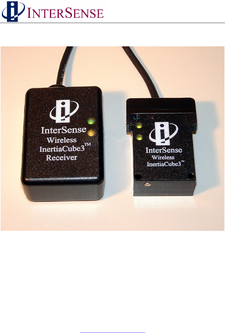
There are two LEDs on the Wireless InertiaCube3 and the InertiaCube3 Receiver. The green
LED on both is a power indicator. When power if first applied to either device, the green LED
will flash 4 times and then stay on steady. If the power to the Wireless InertiaCube3 drops below
5.1 Volts (i.e. if the battery power is failing), the green LED will start to flash indicating a low
power condition and continue flashing until the power is above 5.5 Volts.
Warning: The InertiaCube3 requires 6-9 Volts DC. Voltages above 9 VDC may cause permanent
damage to the device.
Wireless InertiaCube3 Supplemental Manual 7
Doc. No. 072-00096-0E05
The amber LED on both devices indicates wireless traffic. It should be off at start up then turn on
and stay on when the InterSense Library (i.e. isense.dll) is active.
The both devices have PCB antennas. For optimal performance, do not enclose either the
Wireless InertiaCube3 or InertiaCube3 Receiver in metal containers or place close to large metal
surfaces.
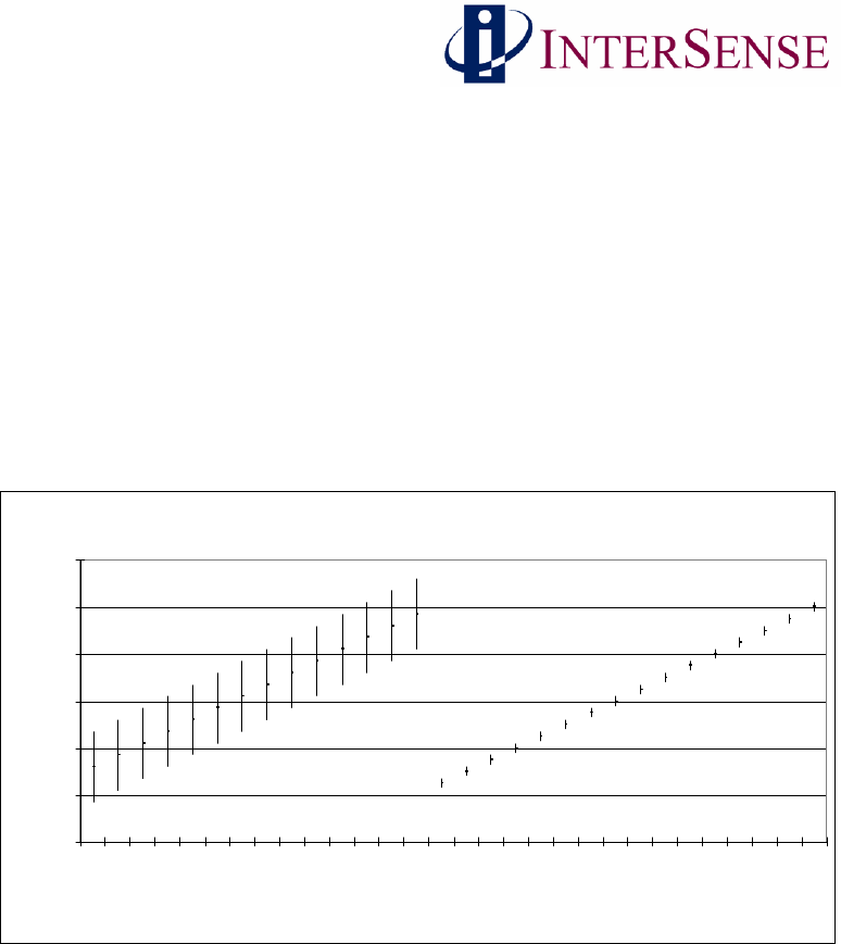
Because these devices use the same frequency at Bluetooth and 802.11 devices there could be
some interference issues if there is heavy wireless traffic in the same area as our devices.
Because the InertiaCube3 devices do not frequency hop but the other major standards do (like
802.11), it probably will not help to change channels to avoid interference with them. Using
the default lower channels (InertiaCube3 Wireless channels 1 to 4) is recommend to avoid
interference in typical environments. The chart below shows the Wireless InertiaCube3 channel
frequency bands with the 802.11b shown as a reference.
2.4 GHz radios
2.38
2.4
2.42
2.44
2.46
2.48
2.5
WLAN ch1
WLAN ch2
cWLAN h3
WLAN ch4
WLAN ch5
WLAN ch6
WLAN ch7
WLAN ch8
WLAN ch9
WLAN ch10
WLAN ch11
WLAN ch12
WLAN ch13
WLAN ch14
IC3 ch1
IC3 ch2
IC3 ch3
IC3 ch4
IC3 Ch5
IC3 ch6
IC3 ch7
IC3 ch8
IC3 ch9
IC3 ch10
IC3 ch11
IC3 ch12
IC3 ch13
IC3 ch14
IC3 ch15
IC3 ch16
frequency (GHz)
Wireless InertiaCube3 Frequency Channels (right) vs 802.11b Channel Bands (left)
Wireless InertiaCube3 Supplemental Manual 8
Doc. No. 072-00096-0E05
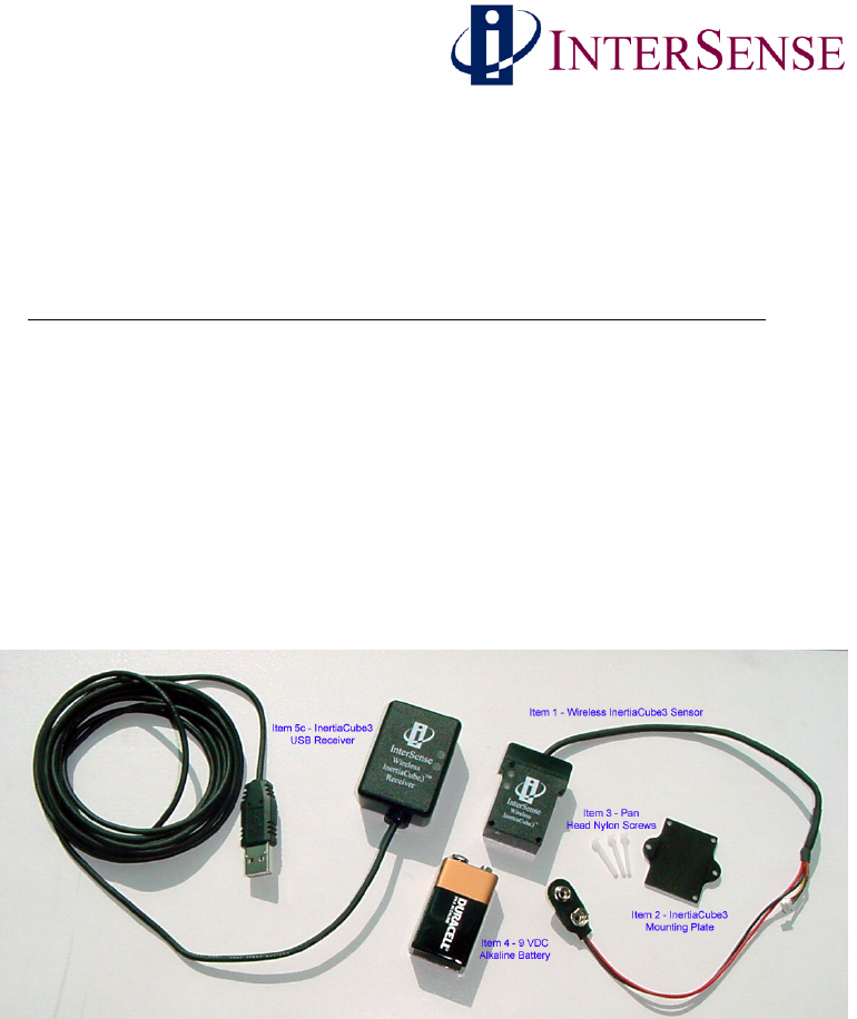
InertiaCube3 Components
The following parts list shows all components that ship with a standard Wireless InertiaCube3
(IC3) under InterSense order number ISC-IC30W-PAK0.
Item Part No. Quantity
1) Wireless IC3 Sensor Cube 100-IMU0W-0301 1
2) IC3 Mounting Plate 083-00104-IC3F 1
3) 2-56 x ¾ Pan Head Nylon Screws 092-P0256-NP12 3
4) 9 VDC Alkaline Battery 060-9VOLT-001 1
5) IC3 Receiver Options one of the two options below 1
IC3 RS232 16 Channel Receiver 100-IC3SW-RX16
IC3 USB 16 Channel Receiver 100-IC3UW-RX16
6) IC3 Serial Receiver Options included if RS232 receiver is chosen
DB Female to RJ11/RJ12 Connector 100-23750-RJ12 Optional
AC/DC +6VDC Power Supply 066-CUI06-0200 Optional
AC Power Cable (country specific) 078-2COND-xx06 Optional
7) Wireless IC3 Product CD Ver. 3.8x or higher 1
Wireless InertiaCube3 Components with USB Receiver Version (Product CD not shown)

Wireless InertiaCube3 Supplemental Manual 9
Doc. No. 072-00096-0E05
Specifications and Performance Characteristics
1.2 Wireless InertiaCube3 Specifications
Degrees of Freedom 3 (Yaw, Pitch and Roll)
Angular Range Full 360° - All Axes
Maximum Angular Rate* 1200° per second
Minimum Angular Rate* 0° per second
RMS Accuracy* 1° in yaw, 0.25° in pitch & roll at 25°C
RMS Angular Resolution* 0.03°
USB Receiver Update Rate 180 Hz (up to two sensors)
120 Hz (three to four sensors)
Serial Interface Update Rate 180 Hz (single sensor only)
Minimum Latency < 6 ms (host OS dependent)
Prediction up to 50 milliseconds
Serial Rate 115.2 kbaud
Interface USB (supports four wireless sensors per receiver)
RS-232 Serial (supports only one wireless sensor)
Size (without mounting plate) 1.232 in x 1.700 in x 0.581 in
(31.3 mm x 43.2 mm x 14.8 mm)
Weight (without battery) 0.7 ounces (20.0 grams)
Battery/I2C Cable Length IC3 Sensor to Battery 9.0 inches (23 cm)
Power InertiaCube3 - 6 VDC, 40 milliamps
InertiaCube3 Radio –6 VDC, 20 milliamps
Operating Temperature Range 0° to 70° C
O/S Compatibility .dll for Windows 98/2k/NT/XP/CE
.so for Linux and SGI IRIX
libisense.dylib for Mac OS X
Software Support SDK with full InterSense API
Ethernet via Windows Control Software
Heading Calibration Software
Windows Wireless Configuration Software
Receiver Power Source USB (direct from USB Host)
Serial (6 VDC External Supply)
Wireless Receiver Size 2.36 in x 1.38 in x 0.79 in
(60 mm x 35 mm x 20 mm)
Wireless Receiver Cable Length 9.84 ft. (3.0 m)
Wireless InertiaCube3 Range up to 100 ft. (30 meters)
*Measurements with perceptual enhancement algorithm turned off (= 0)

Wireless InertiaCube3 Supplemental Manual 10
Doc. No. 072-00096-0E05
2 Wireless InertiaCube3 Support Software
Test software and the InterSense Software Development Kit (SDK) delivered with the
InertiaCube3 are provided on the InterSense Support CD with the system. Use the auto install
tool to extract and install the software on your Windows PC.
The core of all InterSense software running on a Windows PC is the isense.dll. When installed
with the auto installer Product CD, the isense.dll is automatically place in the WINDOWS or
WINNT system directory. This library, along with all other InterSense libraries used with other
operating systems, provides a standard interface to all InterSense tracking systems.
Isdemo32.exe is installed in the InterSense\Programs folder. It provides a convenient graphical
interface for testing and configuring the tracker.
IServer.exe (the InterSense Server Application) provides multiple services to applications
requiring tracker data. IServer runs in the system tray, reading the data from the connected
devices at the maximum speed allowed by the operating system. That data is then made available
to other applications that use the InterSense DLL to communicate with the tracker. This allows
multiple applications running at the same time to read data from the same tracking device.
Joystick Emulation Drivers can present any InterSense tracker as a joystick to the operating
system. This provides games, like the Microsoft Flight Simulator, use of the tracker to control
the line of sight. IServer reads tracker data in real time and passes it to the InterSense Joystick
Driver, where it becomes available to all applications capable of reading joystick through
DirectInput Interface.
The JMouse program allows any joystick device to control the "line of sight" in 3D applications,
such as games, flight simulators, etc. It works by converting joystick movement to simulated
mouse commands. JMouse uses DirectInput to detect and read data from joystick devices, so it
requires DirectX version 8.0 or higher. To work with InterSense tracking devices, JMouse
requires InterSense Joystick drivers and IServer to be installed and running.
The InterSense SDK sample programs and instructions are also installed from the CD. The SDK
folder contains InterSense libraries for Windows, WindowsCE (PocketPC), Linux, HP-UX, SGI
IRIX and Mac OS X. Sample code is provided to demonstrate the SDK use in Microsoft Visual
C++, Visual Basic, WindowsCE, Linux and IRIX applications.
USB Drivers are installed in the InterSense\USBDrivers folder. This third party software
supports the USB interface with the Wireless InertiaCube3 Receiver. Depending on your
operating system, you may need to install the USB Drivers as outlined in Appendix B of the
InertiaCube3 Product Manual. Details on the USB drivers and product updates are at
http://www.ftdichip.com.
The deviceTool utility is used to set or change wireless communication channels and is installed
in InterSense\DeviceTool. Use of this utility is described in Section 4 of this manual.
Please review the installed documentation in InterSense\Documents for additional information
and Product Manuals.
Wireless InertiaCube3 Supplemental Manual 11
Doc. No. 072-00096-0E05
3 Wireless Configuration with deviceTool
deviceTool is an application used to test and configure the Wireless InertiaCube3 and the
Wireless InertiaCube3 Receiver. To use deviceTool, you must have the Wireless InertiaCube3
Receiver(s) connected to the Windows PC running deviceTool. Also, any of the Wireless
InertiaCube3(s) that are being tested or configured, must be powered and within range of the
Wireless InertiaCube3 Receiver(s).
There are 16 channels available for the InertiaCube3 to use. Only one channel number can be
assigned to each receiver that is in the same area (within a 100 foot diameter of the Wireless
InertiaCube3 Receiver). Each receiver can have multiple InertiaCube3s (up to four) associated
with it. You may need to use deviceTool to change the channel of a receiver and its associated
InertiaCube3s or to change the association between InertiaCube3s and their receivers.
Warning: When using Device tool, it’s a good idea to make sure that only the devices that you
want to change are powered on so other devices are not accidentally changed.
3.1 Finding all Wireless InertiaCube3 Devices
To use deviceTool go to the InterSense\DeviceTool directory from your installed InterSense
support software, then start the deviceTool.exe program. The following window appears.
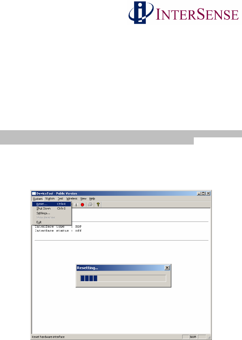
Under the System menu item, select Reset (or click on the yellow light bulb icon in the tool bar).
This will initialize the interface and cause deviceTool to search all the communication ports for
attached receivers and any InertiaCube3s that are paired with them.
Wireless InertiaCube3 Supplemental Manual 12
Doc. No. 072-00096-0E05
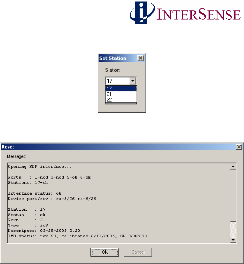
DeviceTool will then prompt you to choose an InertiaCube3 if more than one is detected (as
shown below).
Some information about the InertiaCube3 will then be displayed. Click OK. (If a warning
appears to say that no station was found, click OK as well).
Wireless InertiaCube3 Supplemental Manual 13
Doc. No. 072-00096-0E05
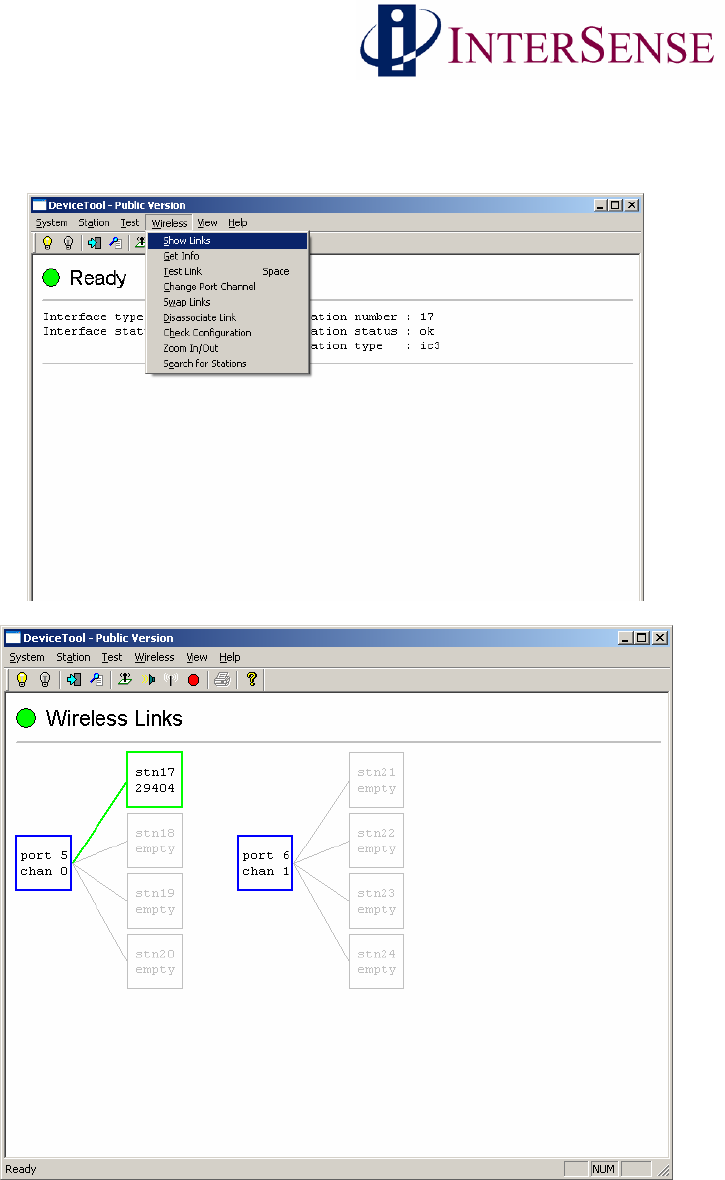
Then under the Wireless menu item select “Show Links”(or click on the antenna icon in the tool
bar). A new display will show representations of the communication ports with receivers
attached to the computer and associated links to InertiaCube3s.
Wireless Links shown for Two InertiaCube3 Receivers and one Wireless InertiaCube3
Wireless InertiaCube3 Supplemental Manual 14
Doc. No. 072-00096-0E05
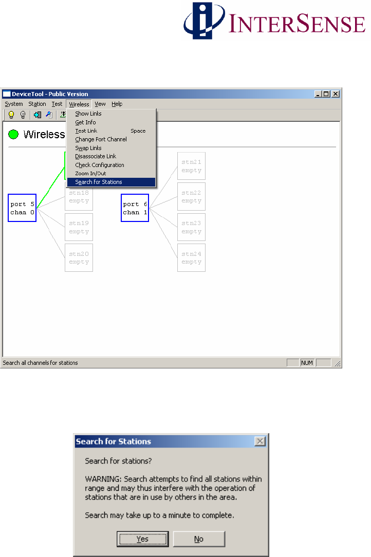
Next, make sure power is applied to all Wireless InertiaCube3s and then select “Search for
Stations” under the Wireless menu to find all Wireless InertiaCube3s in the area.
The dialog box appears warning you to make sure other Wireless InertiaCube3 devices are not
being used by others in the area. Select Yes to continue.
While searching, the yellow light on the Wireless InertiaCube3 Receiver(s) flashes.
Wireless InertiaCube3 Supplemental Manual 15
Doc. No. 072-00096-0E05
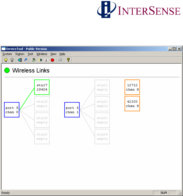
Once the search is complete, following window displays all Wireless InertiaCube3 devices found
in the area. The display will also summarize the device, port, channel, and InertiaCube ID
number.
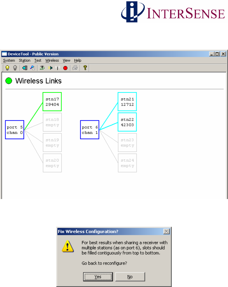
Two Wireless InertiaCube3 Receivers and three Wireless InertiaCube3s
Ports with receivers attached are shown as blue boxes. Links associated with a port are shown as
boxes to the right of the port and are each connected with line to the port (normally colored
green). Links that are not associated with a port (orange) must be assigned to a port before they
can be used. Empty links (gray) have no associated station. Links for InertiaCube3s that are not
operational are shown in red. Links that are not ready (cyan) cannot be used until after a reset.
For the example shown in the deviceTool window above, the search resulted in finding two
Wireless InertiaCube3 Receivers and three Wireless InertiaCube3s. One Wireless InertiaCube3
(ID # 29404) is connected to a receiver on COM port 5 of the Windows PC via wireless channel
0. The second Wireless InertiaCube3 Receiver is connected on COM port 6 of the Windows PC
and is set to wireless channel 1 with no IneriaCube3s connected. The two additional Wireless
InertiaCube3s (ID #’s 12712 & 42303) are set to wireless channel 8.
Wireless InertiaCube3 Supplemental Manual 16
Doc. No. 072-00096-0E05
Note: The COM port reported by deviceTool can either be a physical or virtual COM port
depending on your Wireless InertiaCube3 Receiver configuration. For USB InertiaCube3
Receivers, the USB driver software assigns a virtual COM port to Windows OS for
communications. For RS-232 Serial receivers, the physical COM port is used & reported by
deviceTool.
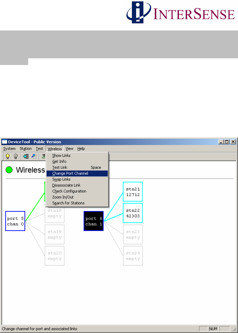
3.2 Changing Receiver Channels
To change the channel used by a receiver InertiaCube3 pair, select the receiver with the mouse
and then under the Wireless menu select “Change Port Channel”. In the dialog box select the
new channel, (Make sure it is not already used by another attached receiver). Valid channels are
0-15. deviceTool will change the receiver and associated InertiaCube3 to the new channel. The
new settings will automatically be stored in non-volatile memory. See deviceTool windows
below.
Changing Receiver Port Number
Wireless InertiaCube3 Supplemental Manual 17
Doc. No. 072-00096-0E05
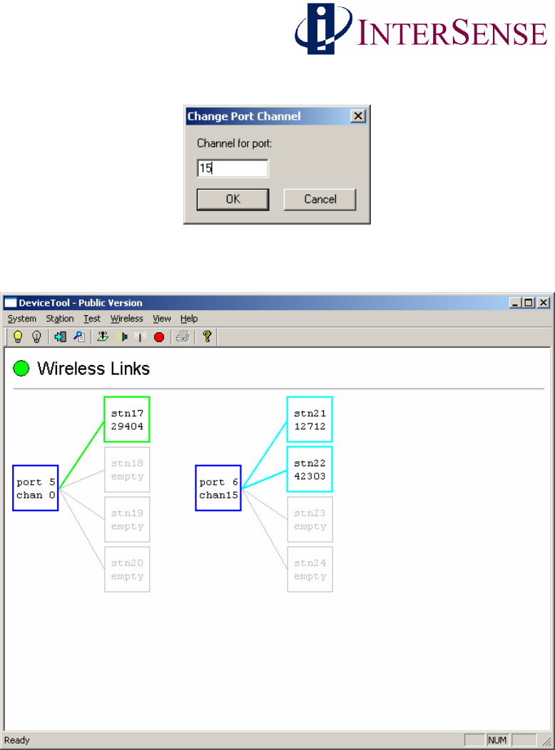
The following dialog box appears asking for a wireless channel number.
Finally the window below confirms the wireless channel number change (here the channel is
changed from 1 to 15).
Wireless InertiaCube3 Supplemental Manual 18
Doc. No. 072-00096-0E05
3.3 Attach Wireless InertiaCube3 to Wireless Receiver
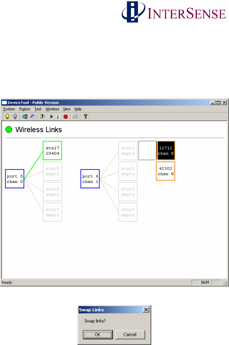
First, find all available InertiaCube3s on all channels. Under the Wireless menu item select
“Search for Stations”. This causes one of the receivers to sequentially go through all 16 channels
searching for available Wireless InertiaCube3s. When deviceTool is done searching, it will
display wireless InertiaCube3s that are not associated to a receiver as orange boxes and those
already attached to a receiver are displayed as green boxes. To associate one of these
InertiaCube3s on another channel to the receiver, just drag the InertiaCube3 to an empty link of a
receiver (outlined in grey). The following dialog box appears.
Wireless InertiaCube3 Supplemental Manual 19
Doc. No. 072-00096-0E05
The deviceTool Window below shows that all Wireless InertiaCube3 devices are assigned a
channel and linked to a receiver.
If you attempt to link a Wireless InertiaCube3 to a non-contiguous of the receiver, the following
suggestion will appear.
For optimal performance, follow the suggestion above by clicking Yes and reconfigure the
system to use contiguous links to the receiver.
You can exit the deviceTool program when done. As you perform each step, the changes made
are automatically saved in the Wireless InertiaCube3 devices.
Wireless InertiaCube3 Supplemental Manual 20
Doc. No. 072-00096-0E05
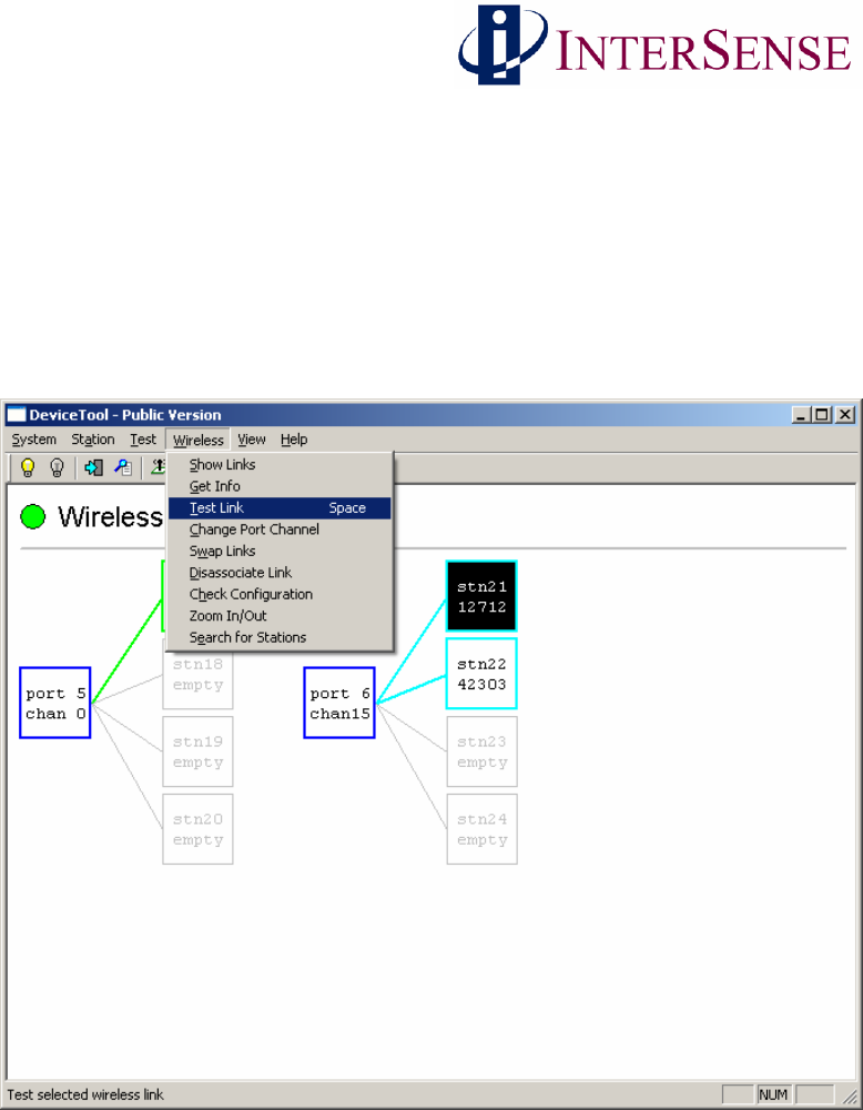
3.4 Testing the Wireless Link of InertiaCube3 Devices
deviceTool is also used to test and verify the wireless communication channels used with the
InertiaCube3. To verify which physical InertiaCube3 corresponds to each box in the window,
select a Wireless InertiaCube3 box and choose “Test Link”from the Wireless menu or press the
space bar. The yellow LED for the InertiaCube3 will light up. Again, if possible, it is best to do
this with just the receivers and InertiaCube3 that you want to associate powered-on (with all
others already configured powered-off) so you don’t accidentally pair the wrong devices.
Wireless InertiaCube3 Supplemental Manual 21
Doc. No. 072-00096-0E05
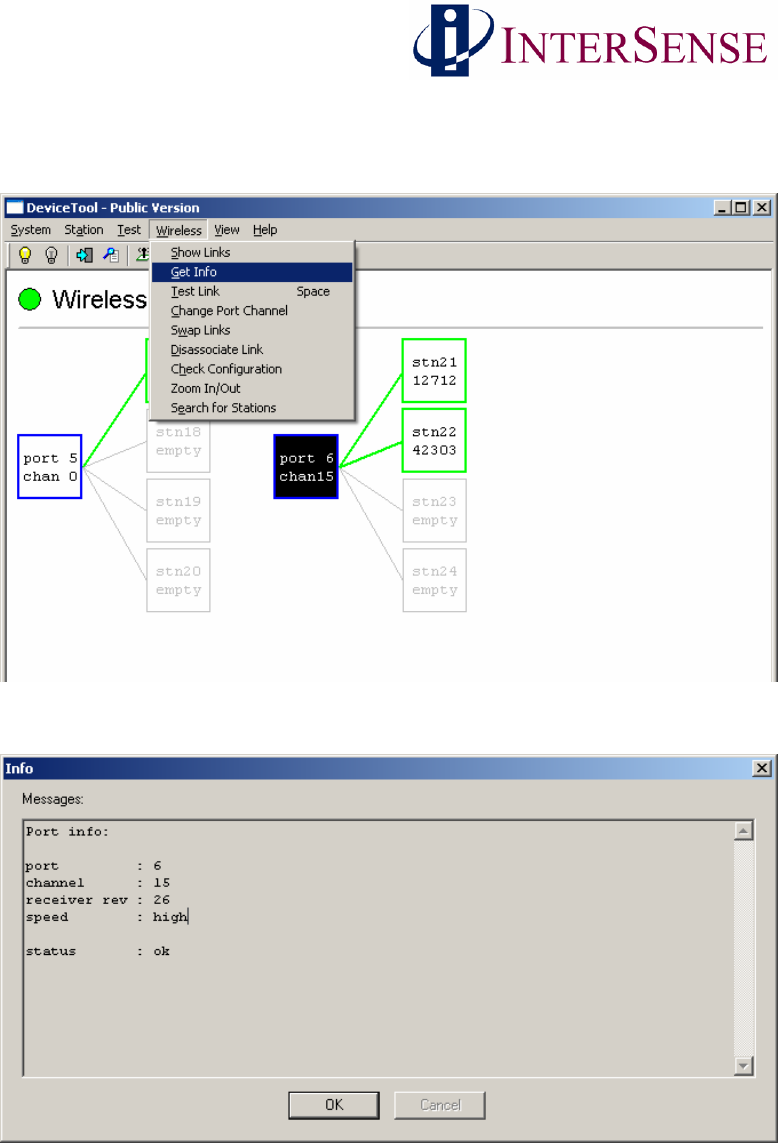
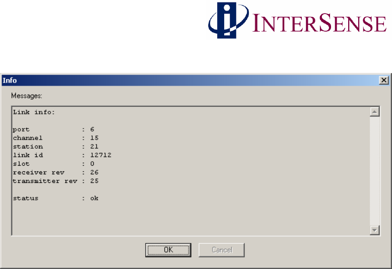
To verify Wireless InertiaCube3 device information (i.e. version number, port number, channel
number, etc…), select either the Wireless Receiver or Wireless InertiaCube3 box in the main
deviceTool window then choose “Get Info”from the Wireless menu. See window below.
A dialog box appears with the device information.
Wireless InertiaCube3 Receiver Information Window
Wireless InertiaCube3 Supplemental Manual 22
Doc. No. 072-00096-0E05
Wireless InertiaCube3 Information Window
4 Wireless InertiaCube3 Power Requirements (Battery)
The Wireless InertiaCube3 requires 5.2 to 9 VDC at a drain of 60 mA. Voltages above 9 Volts
can cause permanent damage to regulators. Voltages below 5.2 VDC will cause the accuracy of
the InertiaCube3 to degrade. The green LED will flash when the detected voltage is at 5.2 VDC,
indicating a low power situation and will continue flash until the power is raised above 5.5 VDC.
If the detected voltage drops below 4.5 VDC, the device will stop operating and go into a very
low drain mode. A non-rechargeable (alkaline) 9 VDC high performance battery can last over 8
hours. Four, non-rechargeable (alkaline), AA or AAA will work as well. Rechargeable AAA
batteries typically only produce 1.2Volts so 4 of them are not sufficient.
5 InertiaCube3 Mounting Recommendations
Magnetometers in 3 axes of the InertiaCube3 are used to establish an absolute heading reference
and to correct for heading gyro drift. To get the best accuracy, the InertiaCube3 should be
mounted as far away from large magnetic sources; either ferrite materials like steel, some types of
batteries or magnets sometimes used in Head/Helmet Mounted Displays (HMDs). For this same
reason you should use the nylon mounting screws supplied with the IC3. Even long non-
magnetic metal screws can effect the magnetic calibration.
Please review the detailed information about mounting and orienting the InertiaCube3 for
optimum performance in Section 3.6 of the InertiCube3 Manual.

Wireless InertiaCube3 Supplemental Manual 23
Doc. No. 072-00096-0E05
The IC3 will produce the same accuracy of results no matter what orientation it is mounted in, but
its natural coordinate system is with the base down and cable coming out the back. If it is
mounted in another orientation then coordinate transformation will either have to occur in your
application or using boresight commands.
6 Dynamic Magnetic Calibration
If there are static field magnetic disturbances even after you have followed the mounting
recommendations closely, you sometimes can compensate for these disturbances by performing a
dynamic magnetic calibration (the full procedure is covered in Section 4.7 of the InertiaCube3
Manual under Compass Calibration Tool).
Indications of the need to perform a magnetic calibration are seen during a 90 degree rotation in
yaw with the InertiaCube reporting a turn close to 90 degrees but then settling at a number off by
more than 10 degrees. If the suspected source of the error if rigidly attached to the IC3, like in a
HMD or a weapons simulator, then a dynamic magnetic calibration may be able to compensate
for most of the offset induced by this source. If the source of error is not attached to the
InertiaCube3, (i.e. the sensor is used within an enclosed metallic environment—automobile
cockpit—but not rigidly attached to this environment) then the magnetic field errors are not static
and cannot be mitigated by using this calibration procedure.