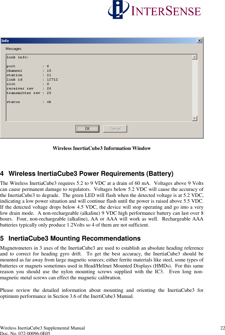
Thales Visionix IMUW301 Wireless InertiaCube3 User Manual WirelessIC3Manual

Thales Visionix, Inc. Wireless InertiaCube3 WirelessIC3Manual

Users Manual

Wireless InertiaCube3 Supplemental Manual 1Doc. No. 072-00096-0E05Wireless InertiaCube3™Wireless InertiaCube3 and ReceiverSupplemental Product Manual for use withWireless InertiaCube3 Serial and USB Interfaces2005 InterSense, Inc.36 Crosby DriveBedford, MA 01730Phone 781 541 6330 • Fax 781 541 6329www.intersense.com
Wireless InertiaCube3 Supplemental Manual 2Doc. No. 072-00096-0E05Supplemental User Manual for InertiaCube3Library Version 3.8x and higherThis supplemental user’s manual for the Wireless InertiaCube3 covers the set up and use ofthe wireless sub-system integrated with the InertiaCube3. Please refer to the “Product Manual for use with InertiCube3 and the InertiaCube3 Processor”(InterSense Document No. 072-00094-0D05) for information about the set-up and operation of the InertiaCube3. Thisdocument is referenced herein at the InertiaCube3 Manual.Contacting InterSensePlease do not hesitate to contact us for any reason. We are here to help and we value yourbusiness.InterSense Inc.36 Crosby Drive, Suite 150Bedford, Massachusetts 01730USATelephone: (781) 541 6330 email: info@intersense.comFax: (781) 541 6329 Internet: www.intersense.comTechnical Support: (781) 541 7624 email: techsupport@intersense.comPatentsThe label below identifies the protection granted by the Government of the United States toInterSense for its products:U.S. Patents5645077, 5807284, 5953683,6162191, 6176837, 6314055,6361507, 6409687, 6424410,6456567, 6474159, 6500008,6529331 and Patents PendingINTERSENSE
Wireless InertiaCube3 Supplemental Manual 3Doc. No. 072-00096-0E05TrademarksInterSense™, InertiaCube™, InertiaCube3TM SoniDisc™, GEOS™, PULSAR™, CONSTELLATION™ are trademarks of InterSense Inc.  All other trademarks are the property oftheir respective owners.Copyright 2005InterSense, Inc.Regulatory Statements and ApprovalsFCC Statements:This device complies with part 15 of the FCC Rules. Operation is subject to the following twoconditions:(1) This device may not cause harmful interference, and(2) This device must accept any interference received, including interference that may causeundesired operation.Caution: changes or modifications not expressly approved by the party responsible forcompliance could void the user’s authority to operate the equipment.NOTE: This equipment has been tested and found to comply with the limits for a ClassB digital device, pursuant to part 15 of the FCC Rules. These limits are designed to providereasonable protection against harmful interference in a residential installation. This equipmentgenerates, uses and can radiate radio frequency energy and, if not installed and used inaccordance with the instructions, may cause harmful interference to radio communications.However, there is no guarantee that interference will not occur in a particular installation. If thisequipment does cause harmful interference to radio or television reception, which can bedetermined by turning the equipment off and on, the user is encouraged to try to correct theinterference by one or more of the following measures:—Reorient or relocate the receiving antenna.—Increase the separation between the equipment and receiver.—Connect the equipment into an outlet on a circuit different from that to which the receiver isconnected.—Consult the dealer or an experienced radio/TV technician for help.Canada - Industry Canada (IC)This Class B digital apparatus meets all requirements of the Canadian Interference-Causing Equipment Regulations.cet appareil de la class B respecte toutes les exigences du Reglement sur le matereil brouiller du Canada.
Wireless InertiaCube3 Supplemental Manual 4Doc. No. 072-00096-0E05Europe - European Union NoticeAll products with the CE marking comply with the EMC Directive (89/336/EEC) and the Low Voltage Directive(73/23/EEC) issued by the Commission of the European Community.Compliance with these directives implies conformity to the following European Norms (in brackets are the equivalentinternational standards).• EN 55022 (CISPR 22) - Electromagnetic Interference• EN 55024 (IEC61000-4-2,3,4,5,6,8,11) - Electromagnetic Immunity• EN 61000-3-2 (IEC610000-3-2) - Power Line Harmonics• EN 61000-3-3 (IEC610000-3-3) - Power Line Flicker• EN 60950 (IEC60950) - Product SafetyProducts labeled with the CExxxx or the CE alert marking contain a radio transmitter that complies with theR&TTE Directive (1999/5/EC) issued by the Commission of the European Community.Compliance with this directive implies conformity to the following European Norms (in brackets are theequivalent international standards).• EN 60950 (IEC60950) - Product Safety• EN 300 328 Technical requirements for radio equipment.• ETS 300 893 and ETS 301 489-17 General EMC requirements for radio equipment.• ETS 301489-1To determine the type of transmitter, check the identification label on your Product.Precautionary StatementsAny changes or modifications to the InertiaCube3 not expressly approved byInterSense will void the warranty and any regulatory compliance issued for thesystem.Do not drop or otherwise shock the tracking devices for they can bepermanently damaged.Do not bend, twist, pull strongly or tamper in any way with any part of thecabling.Take care to avoid electric shocks. Do not plug-in or unplug the power cablewith wet hands.Do not mount InertiaCube3 with steel or other ferrous metal fasteners and donot use a magnetic tipped or ferrous metal screwdriver when mounting theInertiaCube3. Use only non-ferrous fasteners and tools around theInertiaCube3. FAILURE TO FOLLOW THIS PROCEDURE WILL VOIDWARRANTY AND MAY REQUIRE FACTORY RECALABRATION OFSENSOR.
Wireless InertiaCube3 Supplemental Manual 5Doc. No. 072-00096-0E05TABLE OF CONTENTS1 SYSTEM DESCRIPTION...................................................................................... 61.1 WIRELESS INERTIACUBE3 OPERATION.................................................................. 61.2 INERTIACUBE3 COMPONENTS...............................................................................82 SPECIFICATIONS AND PERFORMANCE CHARACTERISTICS ................ 92.1 WIRELESS INERTIACUBE3 SPECIFICATIONS...........................................................93 WIRELESS INERTIACUBE3 SUPPORT SOFTWARE .................................. 104 WIRELESS CONFIGURATION WITH DEVICETOOL................................. 114.1 FINDING ALL WIRELESS INERTIACUBE3 DEVICES ............................................... 114.2 CHANGING RECEIVER CHANNELS ....................................................................... 164.3 ATTACH WIRELESS INERTIACUBE3TO WIRELESS RECEIVER............................... 184.4 TESTING THE WIRELESS LINK OF INERTIACUBE3 DEVICES.................................. 205 WIRELESS INERTIACUBE3 POWER REQUIREMENTS (BATTERY) ..... 226 INERTIACUBE3 MOUNTING RECOMMENDATIONS................................ 227 DYNAMIC MAGNETIC CALIBRATION......................................................... 23
Wireless InertiaCube3 Supplemental Manual 6Doc. No. 072-00096-0E051 System DescriptionCongratulations for buying the smallest, precision orientation tracker on the market! Thistechnology offers you several advantages:Very low latencyWireless range up to 100 feet (30 meters)Smooth, jitter-free trackingLow power consumptionThe Wireless InertiaCube3 is an inertial 3-DOF (Degree of Freedom) orientation tracking system.It obtains its motion sensing using a miniature solid-state inertial measurement unit, which sensesangular rate of rotation, gravity, and earth magnetic field along three perpendicular axes. Theangular rates are integrated to obtain the orientation (yaw, pitch, and roll) of the sensor.Gravitometer and compass measurements are used to prevent the accumulation of gyroscopicdrift. The Wireless InertiaCube3 sensor can be remotely powered providing orientation data via awireless link to a host PC computer.1.1 Wireless InertiaCube3 OperationThe InertiaCube3 is a monolithic part based on micro-electro-mechanical systems (MEMS)technology involving no spinning wheels that might generate noise, inertial forces, andmechanical failures. The InertiaCube simultaneously measures 9 physical properties, namelyangular rates, linear accelerations, and magnetic field components along all 3 axes. The theory ofoperation and performance characteristics of the InertiaCube3 are covered in the InertiaCube3Users Manual (http://www.intersense.com/products/downloads/InertiaCube3_Manual.pdf}.The wireless option for the InertiaCube3 uses a 2.4 GHz non-frequency hopping spread spectrumradio module that allows up to 16 different channel selections. The radio modules have very lowlatency, high bandwidth, built in CRC checking, good range, and 60 mA used by the WirelessInertiaCube3.When a wireless device is purchased from InterSense, the InertiaCube3 Receiver and the WirelessInertiaCube3 are on the same channel and should communicate upon initial set-up with no furtherconfiguration. If multiple InertiaCube3 wireless channels are operating in the same area, then thewireless channel configuration software, deviceTool, is used to change channels and pair devices.See the Section 3 for information about using deviceTool.There are two LEDs on the Wireless InertiaCube3 and the InertiaCube3 Receiver. The greenLED on both is a power indicator. When power if first applied to either device, the green LEDwill flash 4 times and then stay on steady. If the power to the Wireless InertiaCube3 drops below5.1 Volts (i.e. if the battery power is failing), the green LED will start to flash indicating a lowpower condition and continue flashing until the power is above 5.5 Volts.Warning: The InertiaCube3 requires 6-9 Volts DC. Voltages above 9 VDC may cause permanentdamage to the device.
Wireless InertiaCube3 Supplemental Manual 7Doc. No. 072-00096-0E05The amber LED on both devices indicates wireless traffic. It should be off at start up then turn onand stay on when the InterSense Library (i.e. isense.dll) is active.The both devices have PCB antennas. For optimal performance, do not enclose either theWireless InertiaCube3 or InertiaCube3 Receiver in metal containers or place close to large metalsurfaces.Because these devices use the same frequency at Bluetooth and 802.11 devices there could besome interference issues if there is heavy wireless traffic in the same area as our devices.Because the InertiaCube3 devices do not frequency hop but the other major standards do (like802.11), it probably will not help to change channels to avoid interference with them. Usingthe default lower channels (InertiaCube3 Wireless channels 1 to 4) is recommend to avoidinterference in typical environments. The chart below shows the Wireless InertiaCube3 channelfrequency bands with the 802.11b shown as a reference.2.4 GHz radios2.382.42.422.442.462.482.5WLAN ch1WLAN ch2cWLAN h3WLAN ch4WLAN ch5WLAN ch6WLAN ch7WLAN ch8WLAN ch9WLAN ch10WLAN ch11WLAN ch12WLAN ch13WLAN ch14IC3 ch1IC3 ch2IC3 ch3IC3 ch4IC3 Ch5IC3 ch6IC3 ch7IC3 ch8IC3 ch9IC3 ch10IC3 ch11IC3 ch12IC3 ch13IC3 ch14IC3 ch15IC3 ch16frequency (GHz)Wireless InertiaCube3 Frequency Channels (right) vs 802.11b Channel Bands (left)
Wireless InertiaCube3 Supplemental Manual 8Doc. No. 072-00096-0E05InertiaCube3 ComponentsThe following parts list shows all components that ship with a standard Wireless InertiaCube3(IC3) under InterSense order number ISC-IC30W-PAK0.Item Part No. Quantity1) Wireless IC3 Sensor Cube 100-IMU0W-0301 12) IC3 Mounting Plate 083-00104-IC3F 13) 2-56 x ¾ Pan Head Nylon Screws 092-P0256-NP12 34) 9 VDC Alkaline Battery 060-9VOLT-001 15) IC3 Receiver Options one of the two options below 1IC3 RS232 16 Channel Receiver 100-IC3SW-RX16IC3 USB 16 Channel Receiver 100-IC3UW-RX166) IC3 Serial Receiver Options included if RS232 receiver is chosenDB Female to RJ11/RJ12 Connector 100-23750-RJ12 OptionalAC/DC +6VDC Power Supply 066-CUI06-0200 OptionalAC Power Cable (country specific) 078-2COND-xx06 Optional7) Wireless IC3 Product CD Ver. 3.8x or higher 1Wireless InertiaCube3 Components with USB Receiver Version (Product CD not shown)
Wireless InertiaCube3 Supplemental Manual 9Doc. No. 072-00096-0E05Specifications and Performance Characteristics1.2 Wireless InertiaCube3 SpecificationsDegrees of Freedom 3 (Yaw, Pitch and Roll)Angular Range Full 360° - All AxesMaximum Angular Rate* 1200° per secondMinimum Angular Rate* 0° per secondRMS Accuracy* 1° in yaw, 0.25° in pitch & roll at 25°CRMS Angular Resolution* 0.03°USB Receiver Update Rate 180 Hz (up to two sensors)120 Hz (three to four sensors)Serial Interface Update Rate 180 Hz (single sensor only)Minimum Latency < 6 ms (host OS dependent)Prediction up to 50 millisecondsSerial Rate 115.2 kbaudInterface USB (supports four wireless sensors per receiver)RS-232 Serial (supports only one wireless sensor)Size (without mounting plate) 1.232 in x 1.700 in x 0.581 in(31.3 mm x 43.2 mm x 14.8 mm)Weight (without battery) 0.7 ounces (20.0 grams)Battery/I2C Cable Length IC3 Sensor to Battery 9.0 inches (23 cm)Power InertiaCube3 - 6 VDC, 40 milliampsInertiaCube3 Radio –6 VDC, 20 milliampsOperating Temperature Range 0° to 70° CO/S Compatibility .dll for Windows 98/2k/NT/XP/CE.so for Linux and SGI IRIXlibisense.dylib for Mac OS XSoftware Support SDK with full InterSense APIEthernet via Windows Control SoftwareHeading Calibration SoftwareWindows Wireless Configuration SoftwareReceiver Power Source USB (direct from USB Host)Serial (6 VDC External Supply)Wireless Receiver Size 2.36 in x 1.38 in x 0.79 in(60 mm x 35 mm x 20 mm)Wireless Receiver Cable Length 9.84 ft. (3.0 m)Wireless InertiaCube3 Range up to 100 ft. (30 meters)*Measurements with perceptual enhancement algorithm turned off (= 0)
Wireless InertiaCube3 Supplemental Manual 10Doc. No. 072-00096-0E052 Wireless InertiaCube3 Support SoftwareTest software and the InterSense Software Development Kit (SDK) delivered with theInertiaCube3 are provided on the InterSense Support CD with the system. Use the auto installtool to extract and install the software on your Windows PC.The core of all InterSense software running on a Windows PC is the isense.dll. When installedwith the auto installer Product CD, the isense.dll is automatically place in the WINDOWS orWINNT system directory. This library, along with all other InterSense libraries used with otheroperating systems, provides a standard interface to all InterSense tracking systems.Isdemo32.exe is installed in the InterSense\Programs folder. It provides a convenient graphicalinterface for testing and configuring the tracker.IServer.exe (the InterSense Server Application) provides multiple services to applicationsrequiring tracker data. IServer runs in the system tray, reading the data from the connecteddevices at the maximum speed allowed by the operating system. That data is then made availableto other applications that use the InterSense DLL to communicate with the tracker. This allowsmultiple applications running at the same time to read data from the same tracking device.Joystick Emulation Drivers can present any InterSense tracker as a joystick to the operatingsystem. This provides games, like the Microsoft Flight Simulator, use of the tracker to controlthe line of sight. IServer reads tracker data in real time and passes it to the InterSense JoystickDriver, where it becomes available to all applications capable of reading joystick throughDirectInput Interface.The JMouse program allows any joystick device to control the "line of sight" in 3D applications,such as games, flight simulators, etc. It works by converting joystick movement to simulatedmouse commands. JMouse uses DirectInput to detect and read data from joystick devices, so itrequires DirectX version 8.0 or higher. To work with InterSense tracking devices, JMouserequires InterSense Joystick drivers and IServer to be installed and running.The InterSense SDK sample programs and instructions are also installed from the CD. The SDKfolder contains InterSense libraries for Windows, WindowsCE (PocketPC), Linux, HP-UX, SGIIRIX and Mac OS X. Sample code is provided to demonstrate the SDK use in Microsoft VisualC++, Visual Basic, WindowsCE, Linux and IRIX applications.USB Drivers are installed in the InterSense\USBDrivers folder. This third party softwaresupports the USB interface with the Wireless InertiaCube3 Receiver. Depending on youroperating system, you may need to install the USB Drivers as outlined in Appendix B of theInertiaCube3 Product Manual. Details on the USB drivers and product updates are athttp://www.ftdichip.com.The deviceTool utility is used to set or change wireless communication channels and is installedin InterSense\DeviceTool. Use of this utility is described in Section 4 of this manual.Please review the installed documentation in InterSense\Documents for additional informationand Product Manuals.
Wireless InertiaCube3 Supplemental Manual 11Doc. No. 072-00096-0E053 Wireless Configuration with deviceTooldeviceTool is an application used to test and configure the Wireless InertiaCube3 and theWireless InertiaCube3 Receiver. To use deviceTool, you must have the Wireless InertiaCube3Receiver(s) connected to the Windows PC running deviceTool. Also, any of the WirelessInertiaCube3(s) that are being tested or configured, must be powered and within range of theWireless InertiaCube3 Receiver(s).There are 16 channels available for the InertiaCube3 to use. Only one channel number can beassigned to each receiver that is in the same area (within a 100 foot diameter of the WirelessInertiaCube3 Receiver). Each receiver can have multiple InertiaCube3s (up to four) associatedwith it. You may need to use deviceTool to change the channel of a receiver and its associatedInertiaCube3s or to change the association between InertiaCube3s and their receivers.Warning: When using Device tool, it’s a good idea to make sure that only the devices that you want to change are powered on so other devices are not accidentally changed.3.1 Finding all Wireless InertiaCube3 DevicesTo use deviceTool go to the InterSense\DeviceTool directory from your installed InterSensesupport software, then start the deviceTool.exe program. The following window appears.Under the System menu item, select Reset (or click on the yellow light bulb icon in the tool bar).This will initialize the interface and cause deviceTool to search all the communication ports forattached receivers and any InertiaCube3s that are paired with them.
Wireless InertiaCube3 Supplemental Manual 12Doc. No. 072-00096-0E05DeviceTool will then prompt you to choose an InertiaCube3 if more than one is detected (asshown below).Some information about the InertiaCube3 will then be displayed. Click OK. (If a warningappears to say that no station was found, click OK as well).
Wireless InertiaCube3 Supplemental Manual 13Doc. No. 072-00096-0E05Then under the Wireless menu item select “Show Links”(or click on the antenna icon in the toolbar). A new display will show representations of the communication ports with receiversattached to the computer and associated links to InertiaCube3s.Wireless Links shown for Two InertiaCube3 Receivers and one Wireless InertiaCube3
Wireless InertiaCube3 Supplemental Manual 14Doc. No. 072-00096-0E05Next, make sure power is applied to all Wireless InertiaCube3s and then select “Search for Stations” under the Wireless menu to find all Wireless InertiaCube3s in the area.The dialog box appears warning you to make sure other Wireless InertiaCube3 devices are notbeing used by others in the area. Select Yes to continue.While searching, the yellow light on the Wireless InertiaCube3 Receiver(s) flashes.
Wireless InertiaCube3 Supplemental Manual 15Doc. No. 072-00096-0E05Once the search is complete, following window displays all Wireless InertiaCube3 devices foundin the area. The display will also summarize the device, port, channel, and InertiaCube IDnumber.Two Wireless InertiaCube3 Receivers and three Wireless InertiaCube3sPorts with receivers attached are shown as blue boxes. Links associated with a port are shown asboxes to the right of the port and are each connected with line to the port (normally coloredgreen). Links that are not associated with a port (orange) must be assigned to a port before theycan be used. Empty links (gray) have no associated station. Links for InertiaCube3s that are notoperational are shown in red. Links that are not ready (cyan) cannot be used until after a reset.For the example shown in the deviceTool window above, the search resulted in finding twoWireless InertiaCube3 Receivers and three Wireless InertiaCube3s. One Wireless InertiaCube3(ID # 29404) is connected to a receiver on COM port 5 of the Windows PC via wireless channel0. The second Wireless InertiaCube3 Receiver is connected on COM port 6 of the Windows PCand is set to wireless channel 1 with no IneriaCube3s connected. The two additional WirelessInertiaCube3s (ID #’s 12712 & 42303) are set to wireless channel 8.
Wireless InertiaCube3 Supplemental Manual 16Doc. No. 072-00096-0E05Note: The COM port reported by deviceTool can either be a physical or virtual COM portdepending on your Wireless InertiaCube3 Receiver configuration. For USB InertiaCube3Receivers, the USB driver software assigns a virtual COM port to Windows OS forcommunications. For RS-232 Serial receivers, the physical COM port is used & reported bydeviceTool.3.2 Changing Receiver ChannelsTo change the channel used by a receiver InertiaCube3 pair, select the receiver with the mouseand then under the Wireless menu select “Change Port Channel”. In the dialog box select thenew channel, (Make sure it is not already used by another attached receiver). Valid channels are0-15. deviceTool will change the receiver and associated InertiaCube3 to the new channel. Thenew settings will automatically be stored in non-volatile memory. See deviceTool windowsbelow.Changing Receiver Port Number
Wireless InertiaCube3 Supplemental Manual 17Doc. No. 072-00096-0E05The following dialog box appears asking for a wireless channel number.Finally the window below confirms the wireless channel number change (here the channel ischanged from 1 to 15).
Wireless InertiaCube3 Supplemental Manual 18Doc. No. 072-00096-0E053.3 Attach Wireless InertiaCube3 to Wireless ReceiverFirst, find all available InertiaCube3s on all channels. Under the Wireless menu item select“Search for Stations”. This causes one of the receivers to sequentially go through all 16 channelssearching for available Wireless InertiaCube3s. When deviceTool is done searching, it willdisplay wireless InertiaCube3s that are not associated to a receiver as orange boxes and thosealready attached to a receiver are displayed as green boxes. To associate one of theseInertiaCube3s on another channel to the receiver, just drag the InertiaCube3 to an empty link of areceiver (outlined in grey). The following dialog box appears.
Wireless InertiaCube3 Supplemental Manual 19Doc. No. 072-00096-0E05The deviceTool Window below shows that all Wireless InertiaCube3 devices are assigned achannel and linked to a receiver.If you attempt to link a Wireless InertiaCube3 to a non-contiguous of the receiver, the followingsuggestion will appear.For optimal performance, follow the suggestion above by clicking Yes and reconfigure thesystem to use contiguous links to the receiver.You can exit the deviceTool program when done. As you perform each step, the changes madeare automatically saved in the Wireless InertiaCube3 devices.
Wireless InertiaCube3 Supplemental Manual 20Doc. No. 072-00096-0E053.4 Testing the Wireless Link of InertiaCube3 DevicesdeviceTool is also used to test and verify the wireless communication channels used with theInertiaCube3. To verify which physical InertiaCube3 corresponds to each box in the window,select a Wireless InertiaCube3 box and choose “Test Link”from the Wireless menu or press thespace bar. The yellow LED for the InertiaCube3 will light up. Again, if possible, it is best to dothis with just the receivers and InertiaCube3 that you want to associate powered-on (with allothers already configured powered-off) so you don’t accidentally pair the wrong devices.
Wireless InertiaCube3 Supplemental Manual 21Doc. No. 072-00096-0E05To verify Wireless InertiaCube3 device information (i.e. version number, port number, channelnumber, etc…), select either the Wireless Receiver or Wireless InertiaCube3 box in the maindeviceTool window then choose “Get Info”from the Wireless menu. See window below.A dialog box appears with the device information.Wireless InertiaCube3 Receiver Information Window
Wireless InertiaCube3 Supplemental Manual 22Doc. No. 072-00096-0E05Wireless InertiaCube3 Information Window4 Wireless InertiaCube3 Power Requirements (Battery)The Wireless InertiaCube3 requires 5.2 to 9 VDC at a drain of 60 mA. Voltages above 9 Voltscan cause permanent damage to regulators. Voltages below 5.2 VDC will cause the accuracy ofthe InertiaCube3 to degrade. The green LED will flash when the detected voltage is at 5.2 VDC,indicating a low power situation and will continue flash until the power is raised above 5.5 VDC.If the detected voltage drops below 4.5 VDC, the device will stop operating and go into a verylow drain mode. A non-rechargeable (alkaline) 9 VDC high performance battery can last over 8hours. Four, non-rechargeable (alkaline), AA or AAA will work as well. Rechargeable AAAbatteries typically only produce 1.2Volts so 4 of them are not sufficient.5 InertiaCube3 Mounting RecommendationsMagnetometers in 3 axes of the InertiaCube3 are used to establish an absolute heading referenceand to correct for heading gyro drift. To get the best accuracy, the InertiaCube3 should bemounted as far away from large magnetic sources; either ferrite materials like steel, some types ofbatteries or magnets sometimes used in Head/Helmet Mounted Displays (HMDs). For this samereason you should use the nylon mounting screws supplied with the IC3. Even long non-magnetic metal screws can effect the magnetic calibration.Please review the detailed information about mounting and orienting the InertiaCube3 foroptimum performance in Section 3.6 of the InertiCube3 Manual.
Wireless InertiaCube3 Supplemental Manual 23Doc. No. 072-00096-0E05The IC3 will produce the same accuracy of results no matter what orientation it is mounted in, butits natural coordinate system is with the base down and cable coming out the back. If it ismounted in another orientation then coordinate transformation will either have to occur in yourapplication or using boresight commands.6 Dynamic Magnetic CalibrationIf there are static field magnetic disturbances even after you have followed the mountingrecommendations closely, you sometimes can compensate for these disturbances by performing adynamic magnetic calibration (the full procedure is covered in Section 4.7 of the InertiaCube3Manual under Compass Calibration Tool).Indications of the need to perform a magnetic calibration are seen during a 90 degree rotation inyaw with the InertiaCube reporting a turn close to 90 degrees but then settling at a number off bymore than 10 degrees. If the suspected source of the error if rigidly attached to the IC3, like in aHMD or a weapons simulator, then a dynamic magnetic calibration may be able to compensatefor most of the offset induced by this source. If the source of error is not attached to theInertiaCube3, (i.e. the sensor is used within an enclosed metallic environment—automobilecockpit—but not rigidly attached to this environment) then the magnetic field errors are not staticand cannot be mitigated by using this calibration procedure.

Navigation menu