Thales Visionix IS9RX16 Motion Tracker User Manual IS 900 User Guide v61 RGH
Thales Visionix, Inc. Motion Tracker IS 900 User Guide v61 RGH
UserManual.wiki
>
Thales Visionix
>
IS9RX16 User Manual
>
Manual Part 2
Contents
1.
Manual Part 1
2.
Manual Part 2
Manual Part 2
Navigation menu
Upload a User Manual
Namespaces
Wiki Guide
HTML
PDF
Info
Views
User Manual
Discussion / Help
Navigation
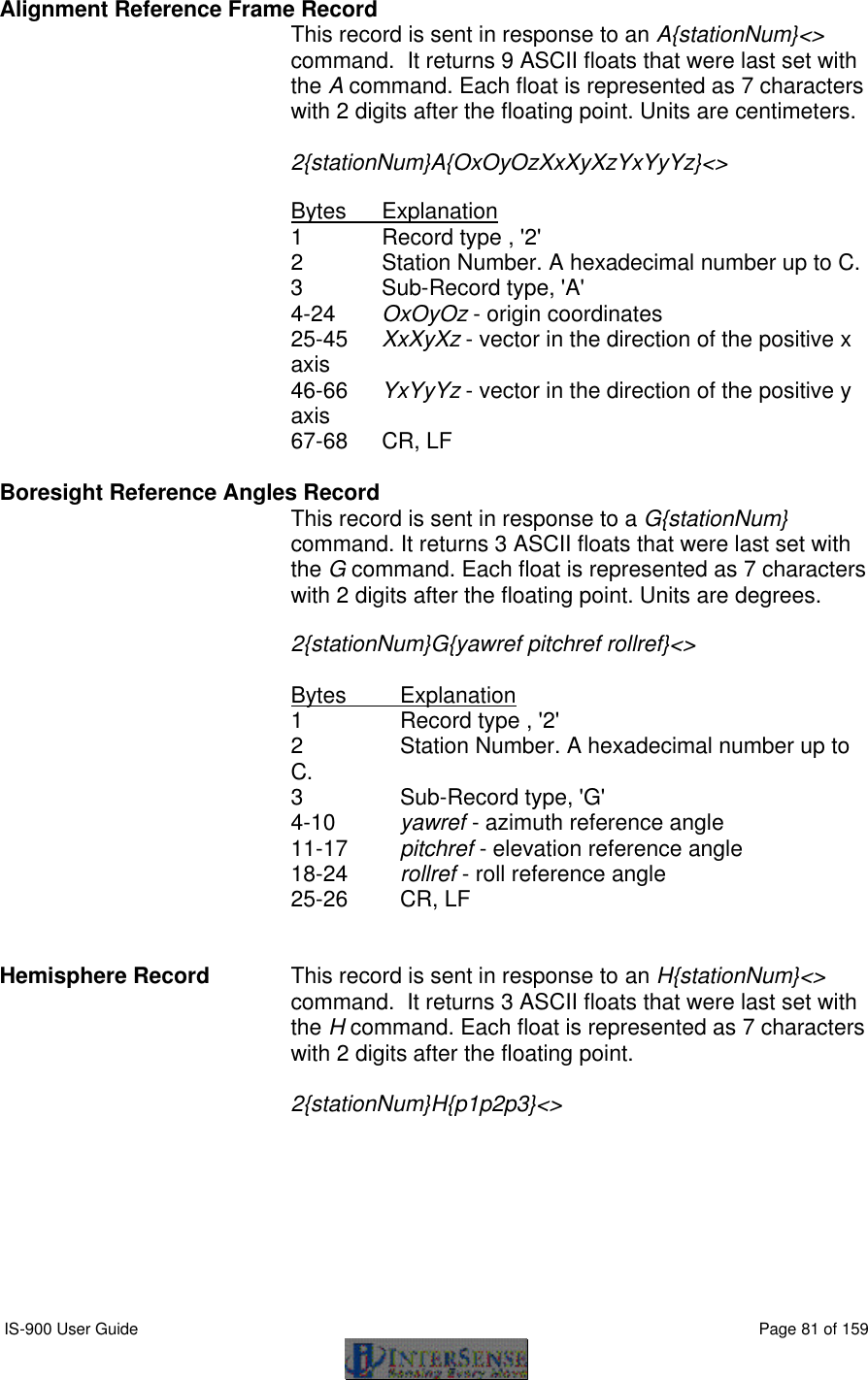
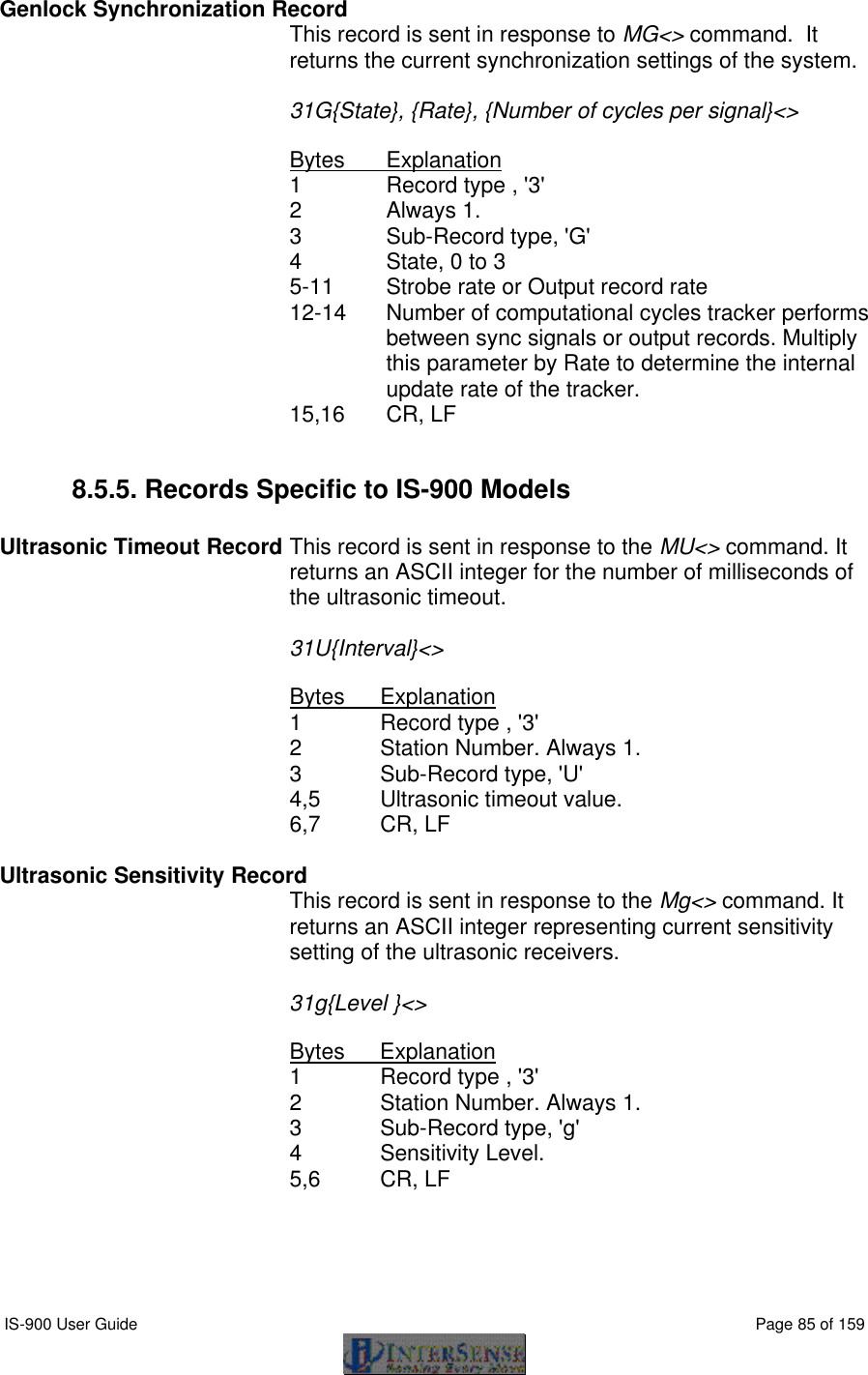
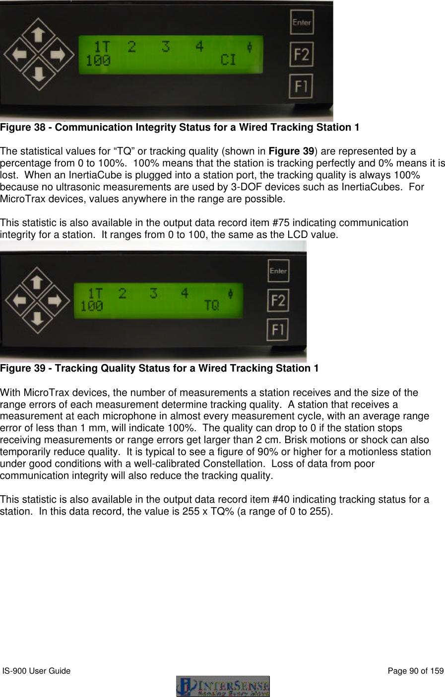
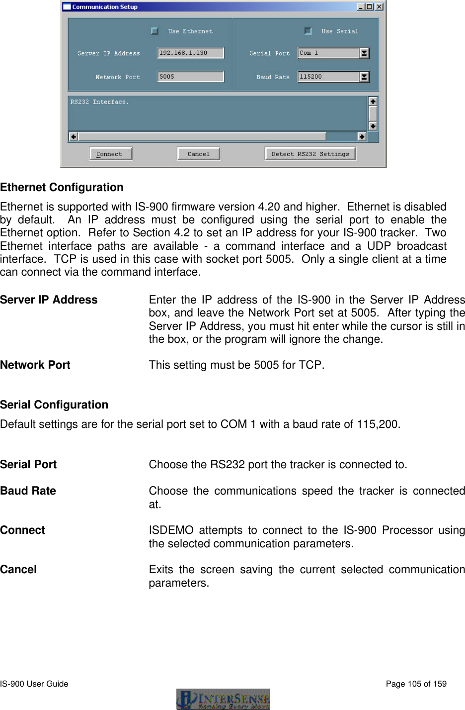
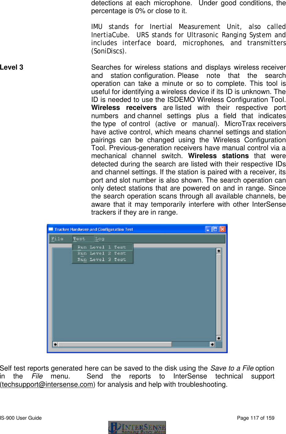
![IS-900 User Guide Page 86 of 159 Fixed PSE Record This record is sent in response to MCF[Fixed PSE number]<> command. It returns the current settings of a single PSE or entire Constellation. 31F{Fixed PSE number}{Fixed PSE record}<> Bytes Explanation 1 Record type , '3' 2 Constellation Number. Always '1' 3 Sub-Record type, 'M' 4-10 Fixed PSE number in ASCII decimal format. 11-40 x, y, z components of position vector in 10.4f ASCII format. Values are in meters. 41-61 x, y, z components of normal vector in 7.2f ASCII format 62-68 Hardware ID code in ASCII format. 69,70 CR, LF Tracking Status Record Sent in response to MP<> command. It returns the tracking status information for all 12 stations. Range measurement is defined as an ultrasonic signal received by a single URM. For example, if the system is configured with two URMs and six ultrasonic beacons (SoniDiscs), 12 range measurements per cycle could be received. 31P{Tracking state record}<> Bytes Explanation 1 Record type, 3'3' 2 Station Number. Always 1. 3 Sub-Record type, 'P' 4 Tracking state identifier for station 1. State can be L if lost, T for tracking, or X for invalid. Please see Section 4.2.10 of this manual for complete description. 5 Number of range measurements received this cycle. 6 Number of range measurements rejected. . … 3+3*N Tracking state identifier for station N. . … 40-44 Update rate per station. 45 Not used, always blank. 46 Genlock identifier. Can be G for Genlock on and synchronized, X if Genlock on but not synchronized, or blank if Genlock is off. 47,48 CR, LF](https://usermanual.wiki/Thales-Visionix/IS9RX16.Manual-Part-2/User-Guide-838146-Page-6.png)
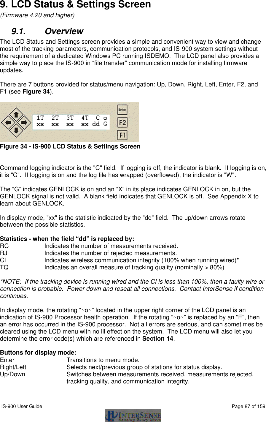
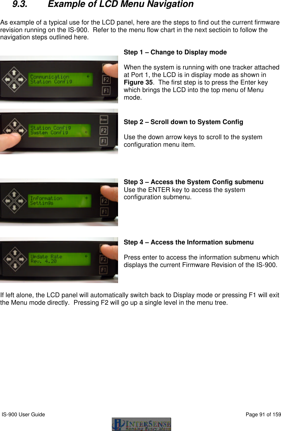
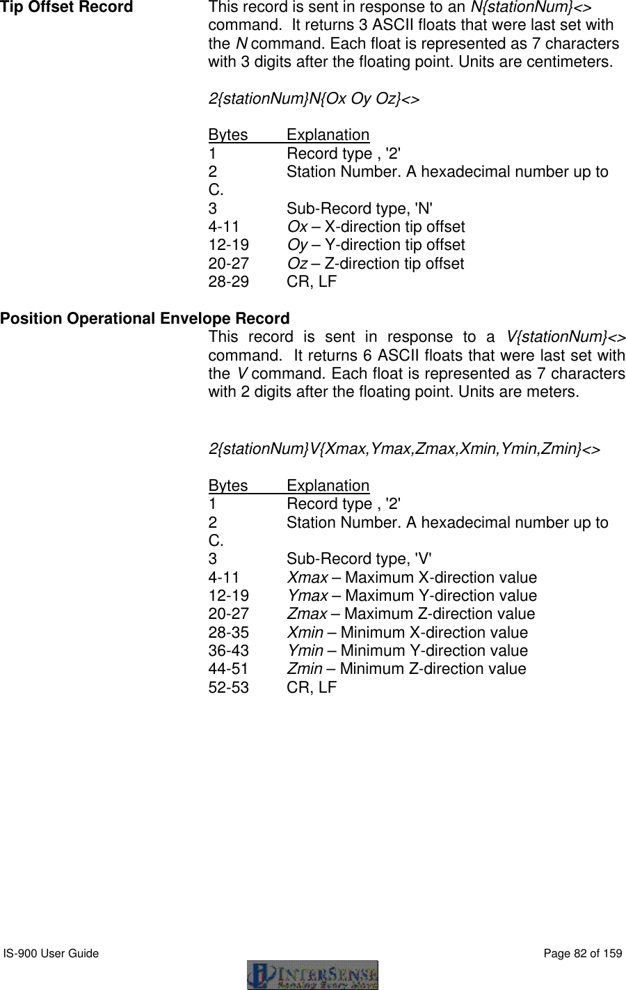
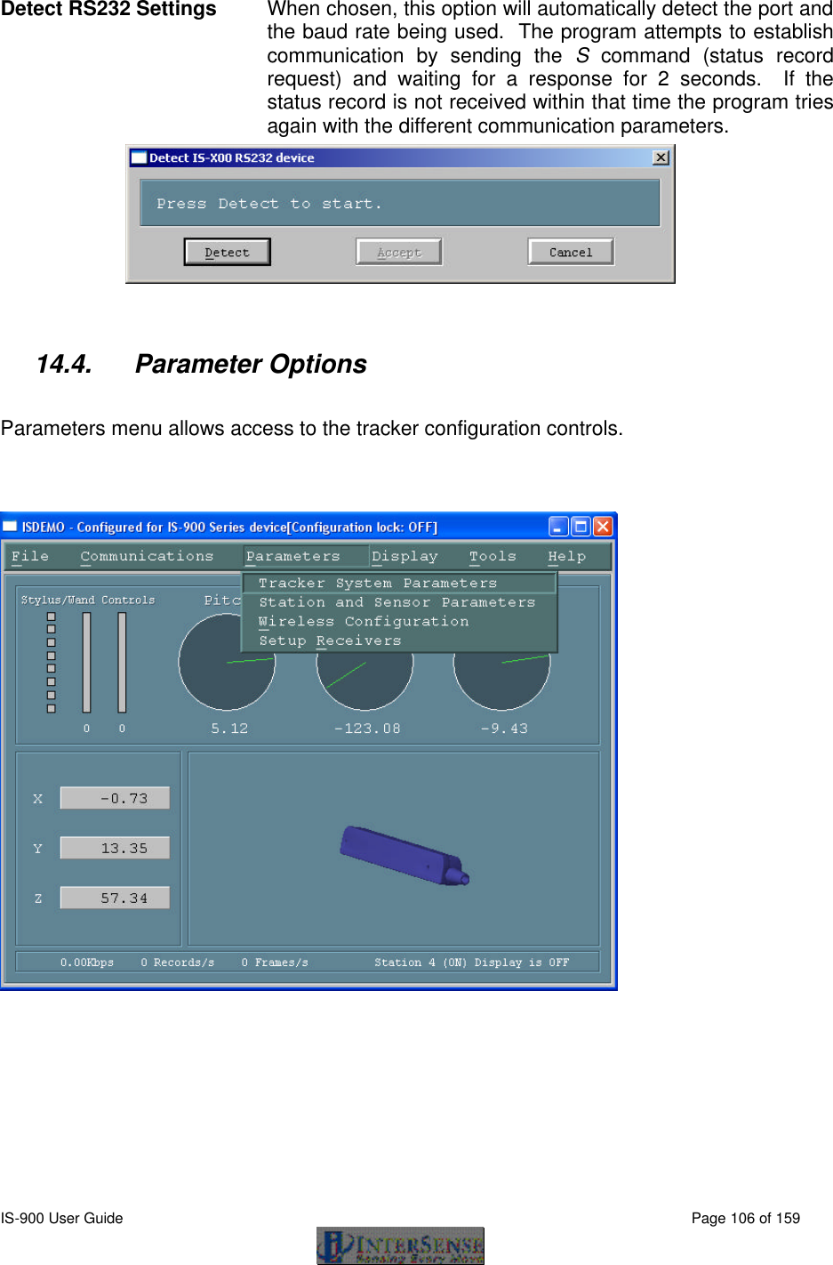
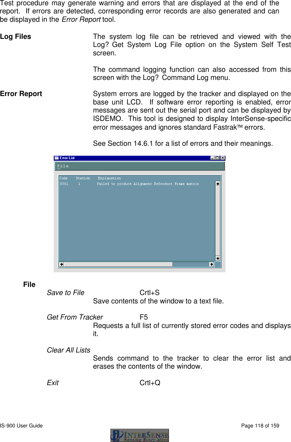
![IS-900 User Guide Page 92 of 159 9.4. IS-900 LCD Menu Flow Chart Figure 40 illustrates the flow chart for the IS-900 LCD menu. LCD menu flow chart for firmware versions 4.20 and greater.Bold boxes represent decision points. Communication Station Config. System Config. Errors Display Reset Encoders (reserved) Exit Menu Baud-Rate Data Output Ethernet BACK 0. 9,600 Baud 1. 19,200 Baud 2. 38,400 Baud 3. 115,200 Baud BACK Binary Form ASCII Form BACK Inches Centimeters BACK Polled Continuous BACK Format Units Sample Mode BACK Set Station Config Station View Station BACK Information Settings Genlock LED Control Command Log Kermit BACK Set Station XX # Prediction Sensitivity Enhancement Compass State BACK View Errors Clear Errors BACK 0. Off 1. Bias 2. Full BACK 0. None 1. Camera 2. Full BACK Station On Station Off BACK 0. Low 1. Medium 2. High 3. Max BACK Prediction: XXms Errors #x xxxxxxH Station [X] State [X] Enhancement [X] Sensitivity [X] Compass [X] Prediction [X] BACK Set Group XX # Phase Point xxx % Output Rate xxx Hz Strobe Rate xxx Hz Rate: xxxx Hz Update Rate Rev. _____ BACK Save Current Restore Factory Restore Saved Set Config Lock BACK State Phase BACK Set Increase Decrease BACK Genlock Off External Internal BACK 0. Off 1. Saved 2. Saved/Session BACK LED's On LED's Off BACK Set Group Set Mode BACK Meas. Received Meas. Rejected Comm. Integrity Tracking Quality BACK Enable Log Disable Log UDP Broadcast IP Address BACK Broadcast On Broadcast Off UDP Port BACK IP Address xxx.xxx.xxx.xxx UDP Port: xxxx Figure 40 - IS-900 LCD Menu Flow Chart](https://usermanual.wiki/Thales-Visionix/IS9RX16.Manual-Part-2/User-Guide-838146-Page-12.png)
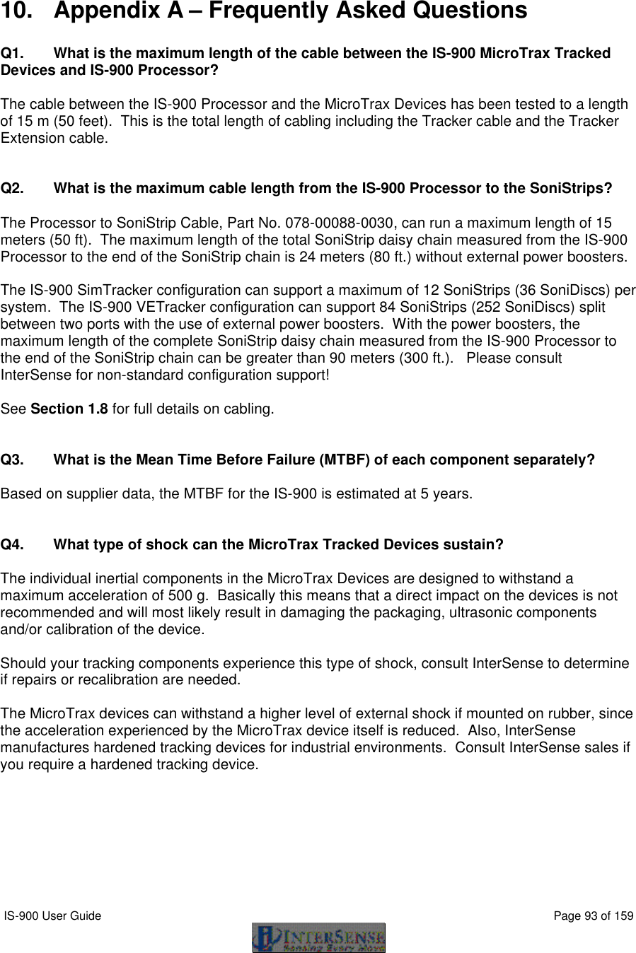


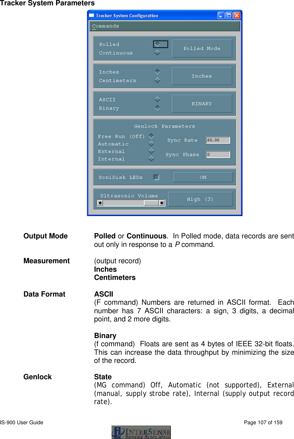
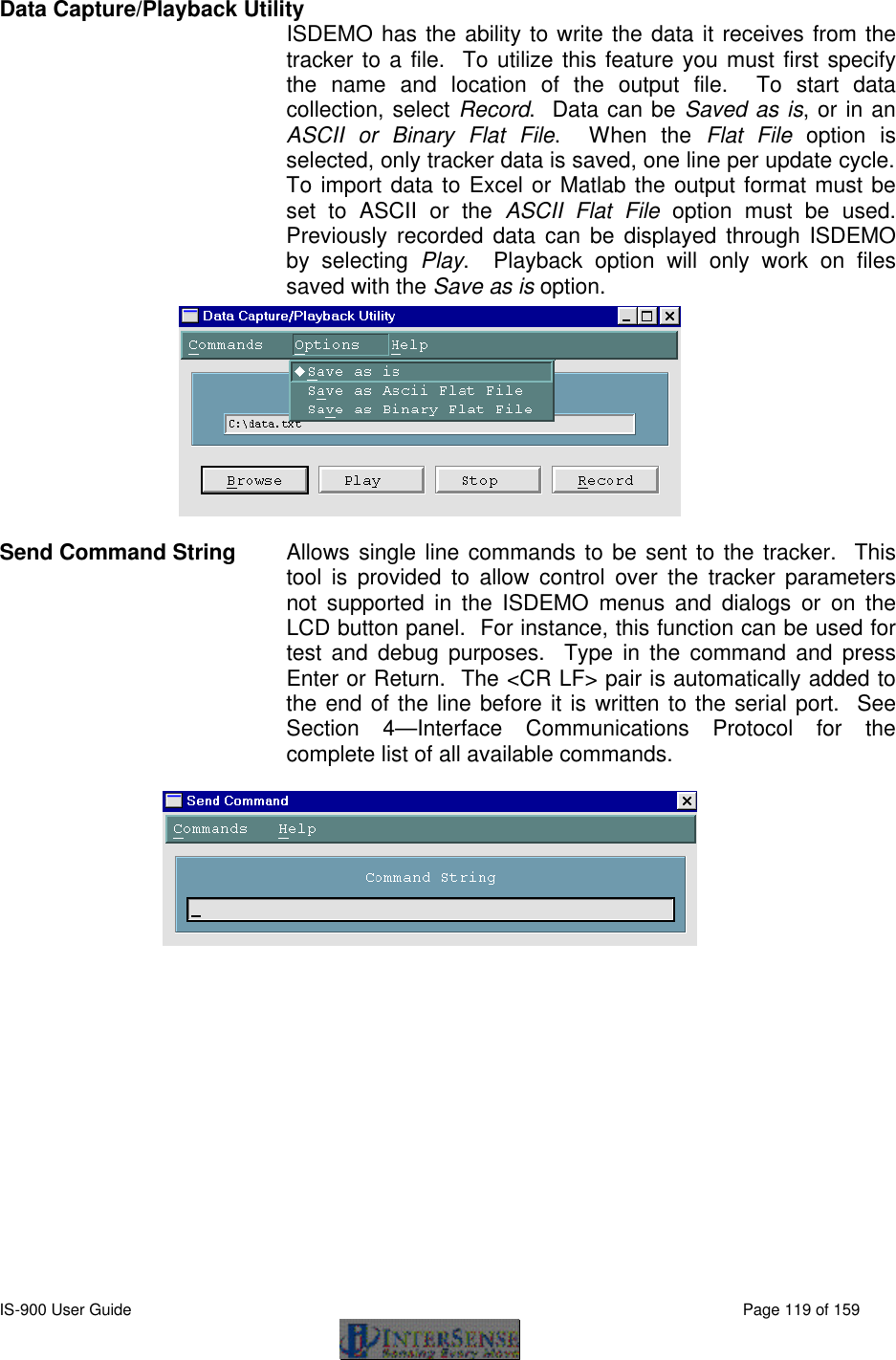
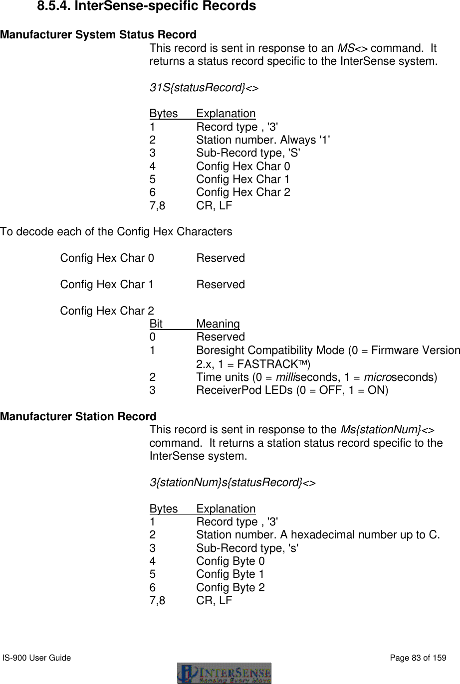
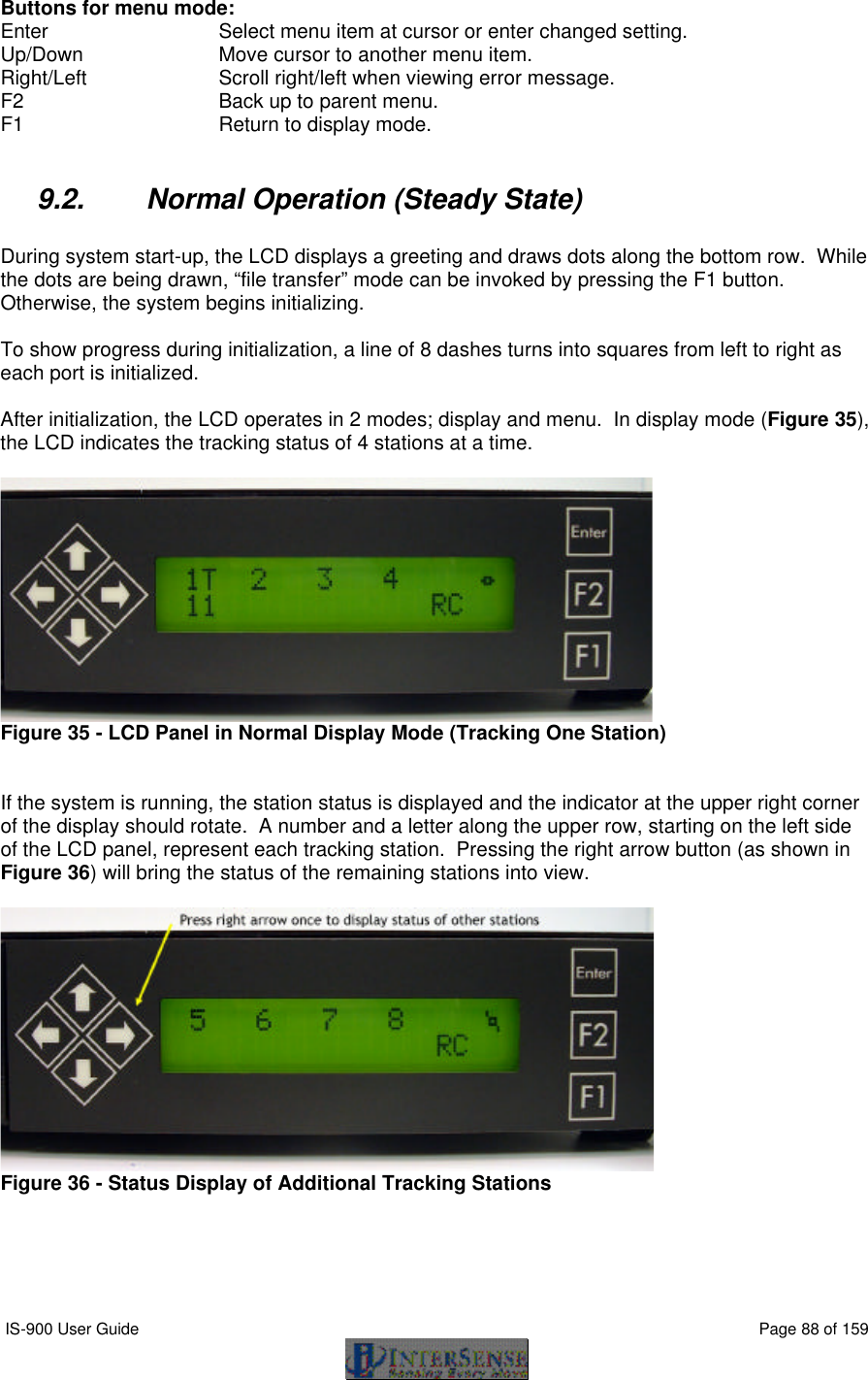
![IS-900 User Guide Page 141 of 159 15.2. Configuring the IS-900 for GENLOCK The default operation of the tracker is free run. That is, the tracker performs updates and, in continuous mode, outputs data records as rapidly as it can. GENLOCK operation causes the tracker to synchronize updates and data record output to an external sync signal or to an internal clock. When external GENLOCK is enabled and a valid sync signal is provided, it may take several seconds to stabilize tracking. If a valid signal not present, the tracker will wait an extra period for the signal, dropping the update rate to half the sync rate. Details are discussed below. Connecting Sync Signal The external sync signal for GENLOCK on an IS-900 is on the back panel of the processor shown in Figure 44. Figure 44 - Back Panel of IS-900, SYNC IN is External GENLOCK Input Connect the sync signal to the BNC connector labeled SYNC IN on the back of the IS-900 Processor. The input interface setting for SYNC IN is controlled by software and access is provided via command or the LCD menu. This setting is saved with the rest of the user settings. Command: MGS[source]<> source 1 TTL 2 NTSC Default is TTL. If source is omitted, the current setting is returned (31GS{source}<>). From the LCD menu, GENLOCK source is selected by choosing: System config → GENLOCK → Source (TTL and NTSC options only).](https://usermanual.wiki/Thales-Visionix/IS9RX16.Manual-Part-2/User-Guide-838146-Page-61.png)
![IS-900 User Guide Page 142 of 159 Enabling GENLOCK via Command Send the C command to the tracker to place it in continuous mode. If the tracker is used in polled mode, its internal updates will be synchronized to the sync signal but data record output will not. Send the InterSense-specific GENLOCK command to the tracker. MG[state,[rate]]<> State 0 Genlock off (free run) 1 Reserved—has no effect on the GENLOCK state. 2 Use external sync, strobe rate specified by rate parameter (manual). 3 Use internal sync, output data records at frequency specified by rate parameter. rate For state 2, the sync strobe rate in hertz. For state 3, the data record output rate in hertz. 30 Hz minimum in either case. Current settings of state and rate are reported if the command is issued without parameters (or invalid ones). The Fastrak command y{state}<> is not recognized by the IS-900, but has the equivalent function the MG command with state equal to 0 or 1. If the Fastrak y{state}<> command is used in your code, remember to manually configure GENLOCK via the LCD menu to the settings required by the application. ISDEMO can be used to send the GENLOCK command using the Send Command String option. GENLOCK settings can be saved to the tracker using ISDEMO, using the ^K command or using the LCD (if equipped). Enabling GENLOCK via LCD Menu Select Communication→Data Output→Sample Mode→Continuous to place the tracker in continuous mode. If the tracker is used in polled mode, its internal updates will be synchronized to the sync signal but data record output will not. Select System Config→GENLOCK→State and then one of the following choices. Off GENLOCK off Manual Use external sync (select strobe rate in 5 Hz increments using arrow buttons, then press the enter button) Internal Use internal sync (select data record output rate in 5 Hz increments using arrows buttons, then press the enter button)](https://usermanual.wiki/Thales-Visionix/IS9RX16.Manual-Part-2/User-Guide-838146-Page-62.png)
![IS-900 User Guide Page 143 of 159 Verifying Synchronization To verify GENLOCK is working with the IS-900, check the GENLOCK indicator in the lower-right corner of the LCD on the front panel of the processor. When GENLOCK is on and stable, the indicator displays “G”, otherwise the indicator displays an “X” indicating GENLOCK is enabled but the processor is not synchronized. If “G” or “X” is not displayed, then GENLOCK is off. Using CrystalEyes™ To configure an IS-900 for use with CrystalEyes™, set the sync signal type to TTL and send the command MG2,120 or MG2,60 to the tracker (assuming the video refresh rate is 60 Hz or 120 Hz per eye). Connect the external sync signal used for the CrystalEyes™ IR emitter to the SYNC IN on the back panel of the IS-900 Processor. Adjusting Phase Point A data record is output once per sync period when the tracker is in continuous mode. The phase point is the time within the sync period at which a data record is transmitted and is adjustable for internal and external GENLOCK. The phase point is specified as a percentage of the sync period. 0% (the default) instructs the tracker to output a data record as soon as possible after the sync period begins. 100% delays the output of a record as much as possible before the next sync period begins. To adjust phase point via command: MGP[+/-]<> Increase/decrease to next/preceding phase point MGP[p]<> Set phase point to percentage specified by p (0 to 100) The current phase point is reported if the command is issued without parameters (or invalid ones). The tracker will accept the first form of the command only after GENLOCK is established. With the second form of the command, the tracker will match the specified phase point as best it can, but typically with far less resolution than 1/100th of the sync period. To set the phase point via the LCD menu, select System Config→Genlock→Phase→Set and change the value with the arrow buttons, then press the enter button. To increase or decrease to the next or previous phase point, select System Config→Genlock→Phase→Increase or →Decrease. Adjust the phase to the latest point in the cycle (for minimum latency) such that the system still behaves smoothly during head rotation (no render cycles last beyond the deadline for the next scan out).](https://usermanual.wiki/Thales-Visionix/IS9RX16.Manual-Part-2/User-Guide-838146-Page-63.png)
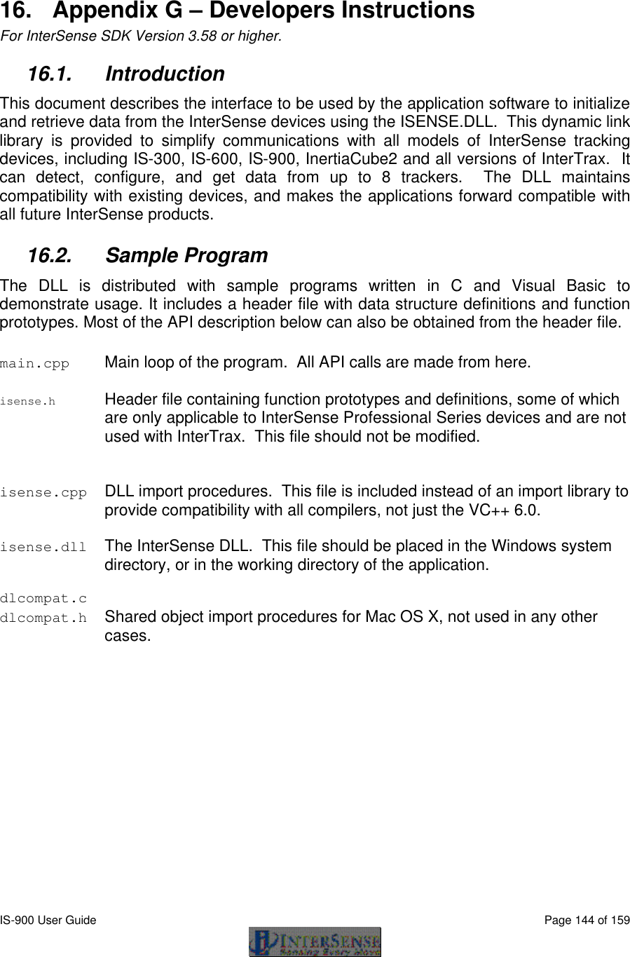
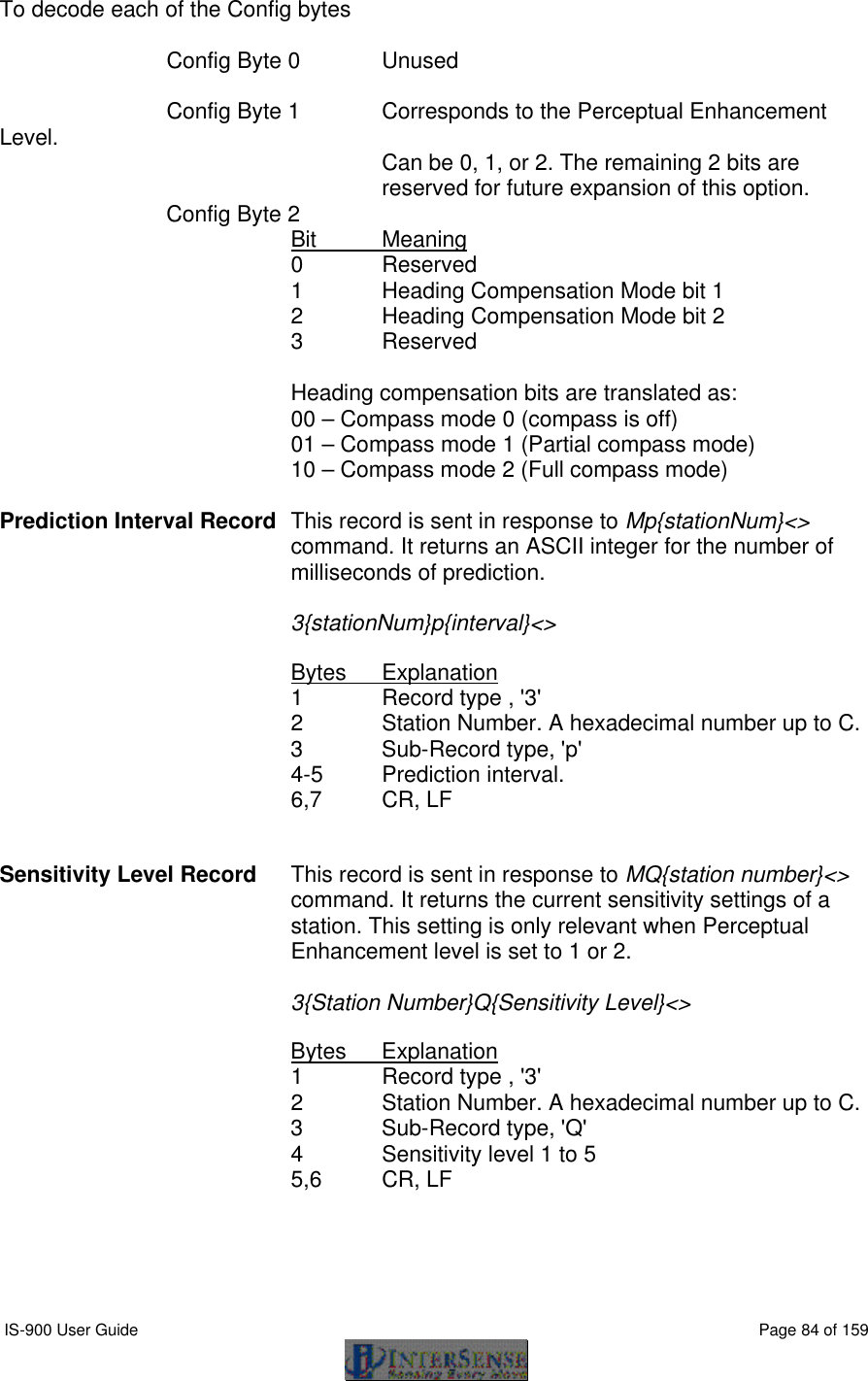
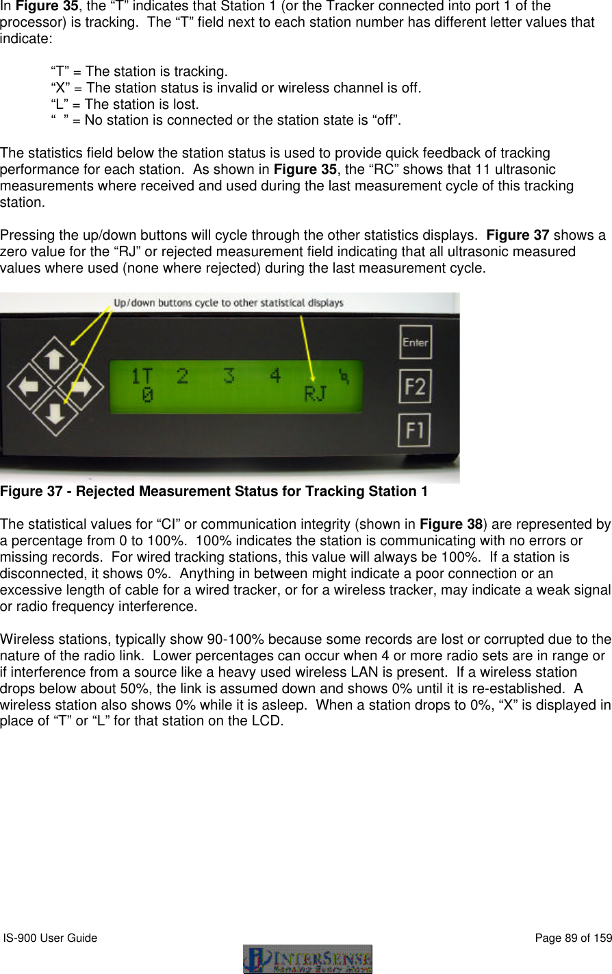
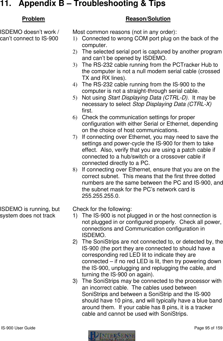
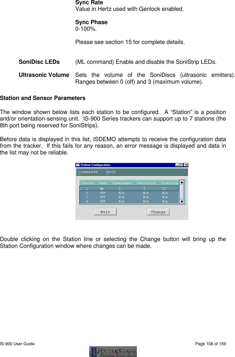
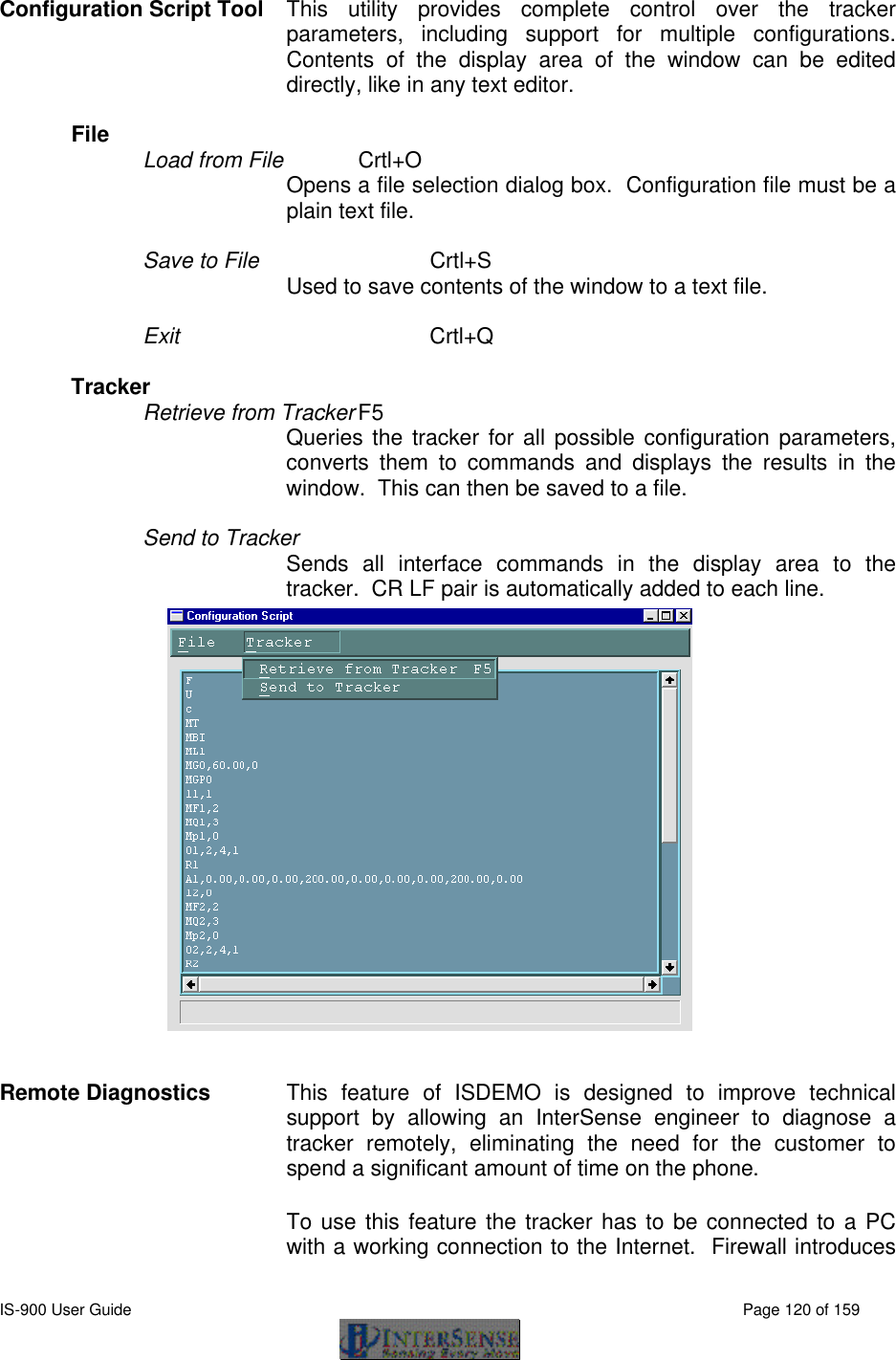
![IS-900 User Guide Page 145 of 159 16.3. Usage The API provides an extensive set of functions that can read and set tracker configuration, but in its simplest form can be limited to just 4 calls, as shown below: void main() { ISD_TRACKER_HANDLE handle; ISD_TRACKER_INFO_TYPE tracker; ISD_TRACKER_DATA_TYPE data; handle = ISD_OpenTracker( NULL, 0, FALSE, FALSE ); if( handle > 0 ) printf( "\n Az El Rl X Y Z \n" ); else printf( "Tracker not found. Press any key to exit" ); while( !kbhit() ) { if( handle > 0 ) { ISD_GetData( handle, &data ); printf( "%7.2f %7.2f %7.2f %7.3f %7.3f %7.3f ", data.Station[0].Orientation[0], data.Station[0].Orientation[1], data.Station[0].Orientation[2], data.Station[0].Position[0], data.Station[0].Position[1], data.Station[0].Position[2] ); ISD_GetCommInfo( handle, &tracker ); printf( "%5.2fKbps %d Records/s \r", tracker.KBitsPerSec, tracker.RecordsPerSec ); } Sleep( 6 ); } ISD_CloseTracker( handle ); }](https://usermanual.wiki/Thales-Visionix/IS9RX16.Manual-Part-2/User-Guide-838146-Page-65.png)
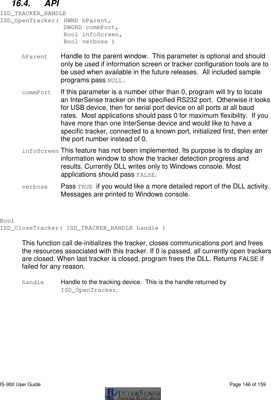
![IS-900 User Guide Page 153 of 159 16.5.2. ISD_STATION_INFO_TYPE This data structure is used to get and set station configuration. typedef struct { DWORD ID; Bool State; Bool Compass; LONG InertiaCube; DWORD Enhancement; DWORD Sensitivity; DWORD Prediction; DWORD AngleFormat; Bool TimeStamped; Bool GetInputs; Bool GetEncoderData; Bool GetAnalogData; DWORD CoordFrame; DWORD dwReserved2; DWORD dwReserved3; DWORD dwReserved4; float TipOffset[3]; float fReserved4; Bool GetCameraData; Bool GetAuxInputs; Bool bReserved3; Bool bReserved4; } ISD_STATION_INFO_TYPE; ID A unique number identifying a station. It is the same as that passed to the ISD_SetStationState and ISD_GetStationState functions and can be 1 to ISD_MAX_STATIONS. State TRUE if on, FALSE if off. InertiaCube2 is considered to be a tracking system consisting of one station, which cannot be turned off, so this field will always be TRUE. Compass Only available for IS-X Series devices and InertiaCube2. For all others this setting is always 2. This controls the state of the compass component of the InertiaCube. Compass is only used when station is configured for GEOS or Dual modes, in Fusion mode compass readings are not used, regardless of this setting. When station is configured for full compass mode, the readings produced by the magnetometers inside the InertiaCube are used as absolute reference orientation for yaw. Compass can be affected by metallic objects and electronic equipment in close proximity to the InertiaCube. When station is configured for partial compass mode, magnetometer readings are used to reduce](https://usermanual.wiki/Thales-Visionix/IS9RX16.Manual-Part-2/User-Guide-838146-Page-73.png)
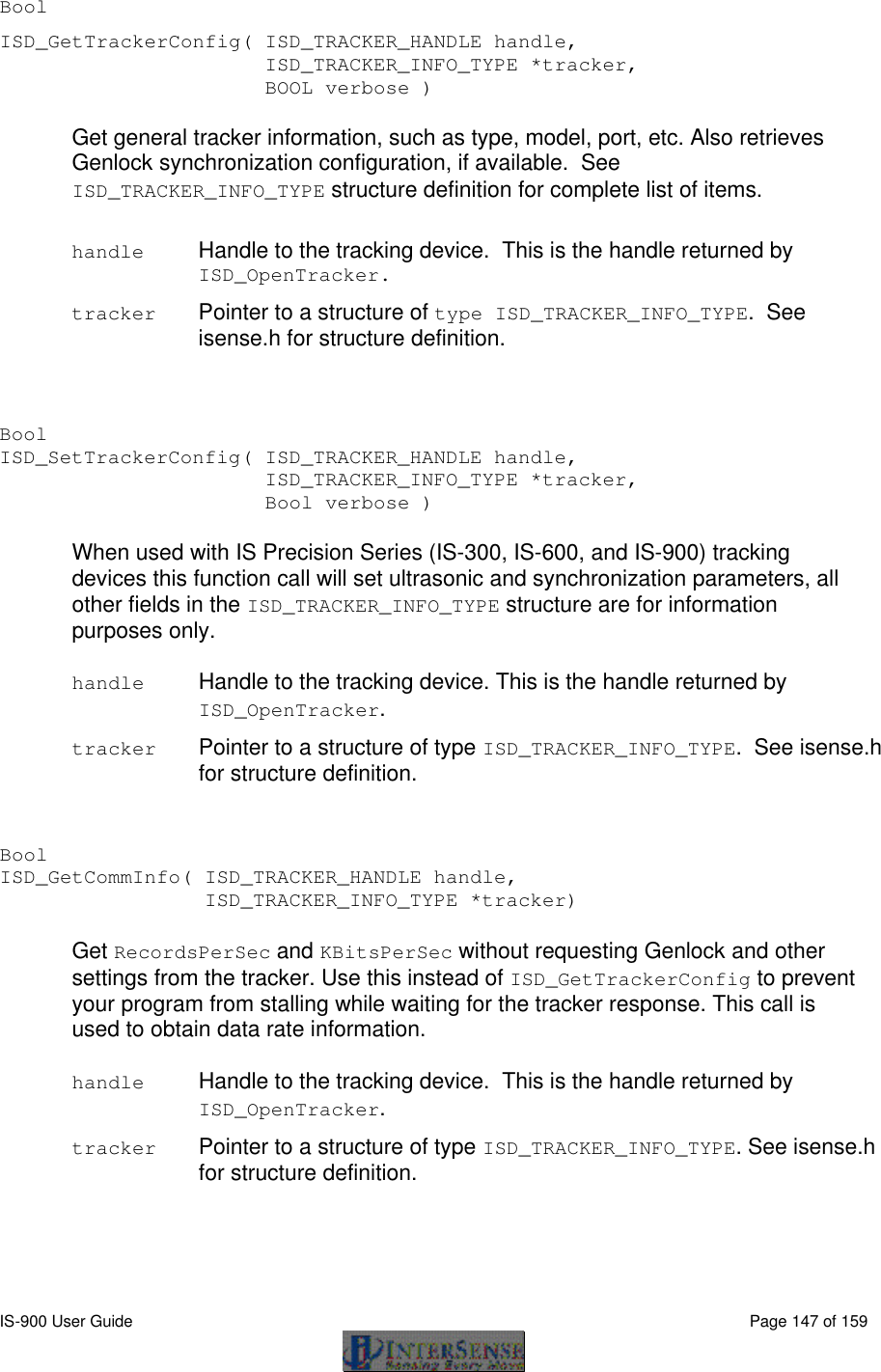
![IS-900 User Guide Page 156 of 159 16.5.3. ISD_STATION_STATE_TYPE This data structure is used to return current data for a station, including position, orientation, time stamp, button and analog channel state. It is passed to ISD_GetData as part of ISD_TRACKER_DATA_TYPE typedef struct { ISD_STATION_STATE_TYPE Station[ISD_MAX_STATIONS]; } ISD_TRACKER_DATA_TYPE; typedef struct { BYTE TrackingStatus; BYTE NewData; BYTE CommIntegrity; BYTE bReserved3; float Orientation[4]; float Position[3]; float TimeStamp; Bool ButtonState[MAX_NUM_BUTTONS]; short AnalogData[MAX_ANALOG_CHANNELS]; BYTE AuxInputs[ISD_MAX_AUX_INPUTS]; LONG lReserved2; LONG lReserved3; LONG lReserved4; DWORD dwReserved1; DWORD dwReserved2; DWORD dwReserved3; DWORD dwReserved4; float fReserved1; float fReserved2; float fReserved3; float fReserved4; } ISD_STATION_STATE_TYPE; TrackingStatus Tracking status byte. Available only with IS-900 firmware versions 4.13 and higher, and isense.dll versions 3.54 and higher. It is a value from 0 to 255 that represents tracking quality. NewData TRUE if this is new data. Every time ISD_GetData is called this flag is reset. CommIntegrity Communication integrity of wireless link.](https://usermanual.wiki/Thales-Visionix/IS9RX16.Manual-Part-2/User-Guide-838146-Page-76.png)
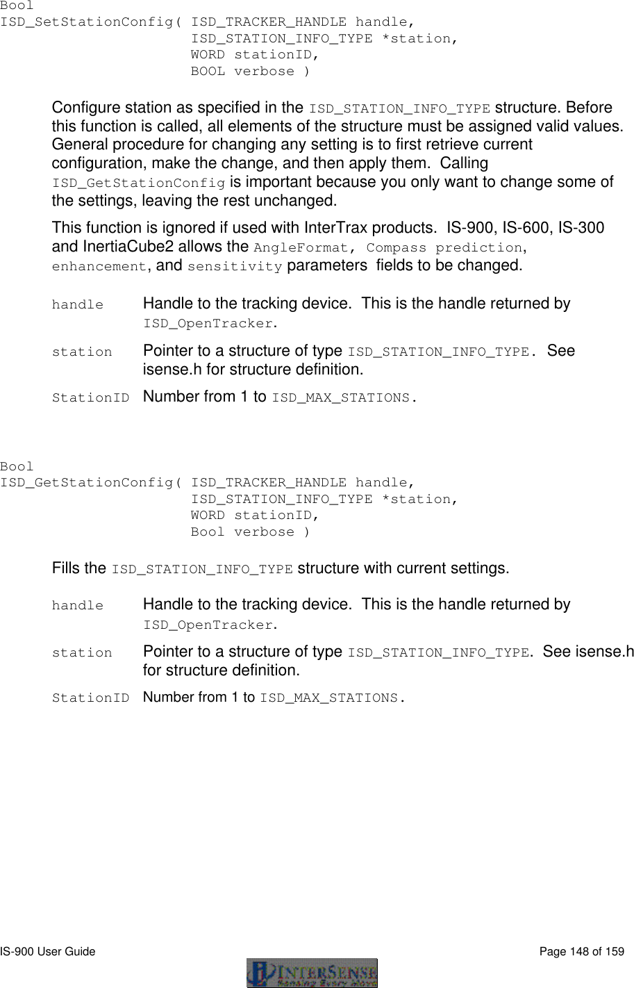
![IS-900 User Guide Page 158 of 159 17. Appendix H – Interface Protocol Commands – Quick Reference For further detail, see: Section 8.2 Standard Fastrak™ Interface Commands, pages 61-69. Section 8.3 Fastrak™ Commands Implemented for Compatibility, page 69. Section 8.4 InterSense specific Commands, pages 69-77. Command Syntax Data Record Request P Output mode C, c Alignment Reference Frame A{stationNum},[Ox,Oy,Oz,Xx,Xy,Xz,Yx,Yy,Yz]<> Reset Alignment Reference Frame R{stationNum}<> Boresight Reference Angles G{stationNum},[yawref, pitchref, rollref]<> Boresight Compatibility Mode MBF<> Switch to Fastrak Compatible mode. MBI<> Switch to Version 2.x Compatible mode. Boresight B{stationNum}<> (Fastrak compatibility mode) MB{stationNum}<> (Version 2.x compatibility mode) Unboresight b{stationNum}<> (Fastrak compatibility mode) Mb{stationNum}<> (Version 2.x compatibility mode) Heading Boresight B{stationNum}<> (Version 2.x compatibility mode) MB{stationNum}<> (Fastrak compatibility mode) Heading Unboresight b{stationNum}<> (Version 2.x compatibility mode) Mb{stationNum}<> (Fastrak compatibility mode) . Set Serial Communication Parameters o{rate,parity,bits,HHS}<> System Record Request S Station Status l{stationNum},[state]<> Output Units Control U Set units to inches. u Set units to centimeters. System control ^K Save current settings to non-volatile memory. W Restore factory default settings. ^Y Restart the firmware to the power up condition. ^S Suspend data transmission. ^Q Resume data transmission. Output record mode F Put in ASCII output mode. F Put in Binary output mode.](https://usermanual.wiki/Thales-Visionix/IS9RX16.Manual-Part-2/User-Guide-838146-Page-78.png)
![IS-900 User Guide Page 159 of 159 Output record list settings O{stationNum},[p1],[p2],[p3],.....,[pn]<> Define Tip Offsets N{stationNum},[Ox, Oy, Oz]<> Position Operational Envelope V{stationNum},[Xmax,Ymax,Zmax,Xmin,Ymin,Zmin]<> Hemisphere H{stationNum},[p1,p2,p3]<> Time Units MT<> Sets to milliseconds. Mt<> Sets to microseconds. Set Current Time to Zero MZ<> Ethernet Communication Parameters MEthIp[address]<> MEthUdp[state]<> MEthUdpPort[port]<> InterSense System Status Record Request MS<> Tracking Status Record Request MP<> Genlock Synchronization MG[State, Rate]<> Genlock Phase MGP[Param]<> Configuration Lock MConfigLockMode{Mode}<> SoniStrip LED Control ML[state] Error reporting ME<> MEC<> ME1<> ME0<> Command Logging MLogOpen<> MLogClose<> MLogClear<> MLogState<> MLogSend<> InterSense Station Status Record Request Ms{stationNum}<> Prediction Interval Mp{stationNum},[Interval]<> Perceptual Enhancement Level MF{stationNum},{Mode}<> Compass Heading Correction MH{stationNum},{state}<> Rotational Sensitivity Level MQ{stationNum},[Sensitivity Level]<> Associate Fixed PSE with a Constellation MCF[FPSE number], [xp, yp, zp, xn, yn, zn, IDcode]<> Disassociate Fixed PSE from Constellation MCf[Fixed PSE number, IDcode]<> Clear All Fixed PSEs (Constellation) MCC<> Apply New Configuration MCe<> Cancel Configuration Session MCx<>](https://usermanual.wiki/Thales-Visionix/IS9RX16.Manual-Part-2/User-Guide-838146-Page-79.png)