The CBORD Group VRC2100 VRC2100 User Manual Proprietary Confidential Information
The CBORD Group, Inc. VRC2100 Proprietary Confidential Information
UserManual.wiki
>
The CBORD Group
>
VRC2100 User Manual
User Manual
Navigation menu
Upload a User Manual
Namespaces
Wiki Guide
HTML
PDF
Info
Views
User Manual
Discussion / Help
Navigation

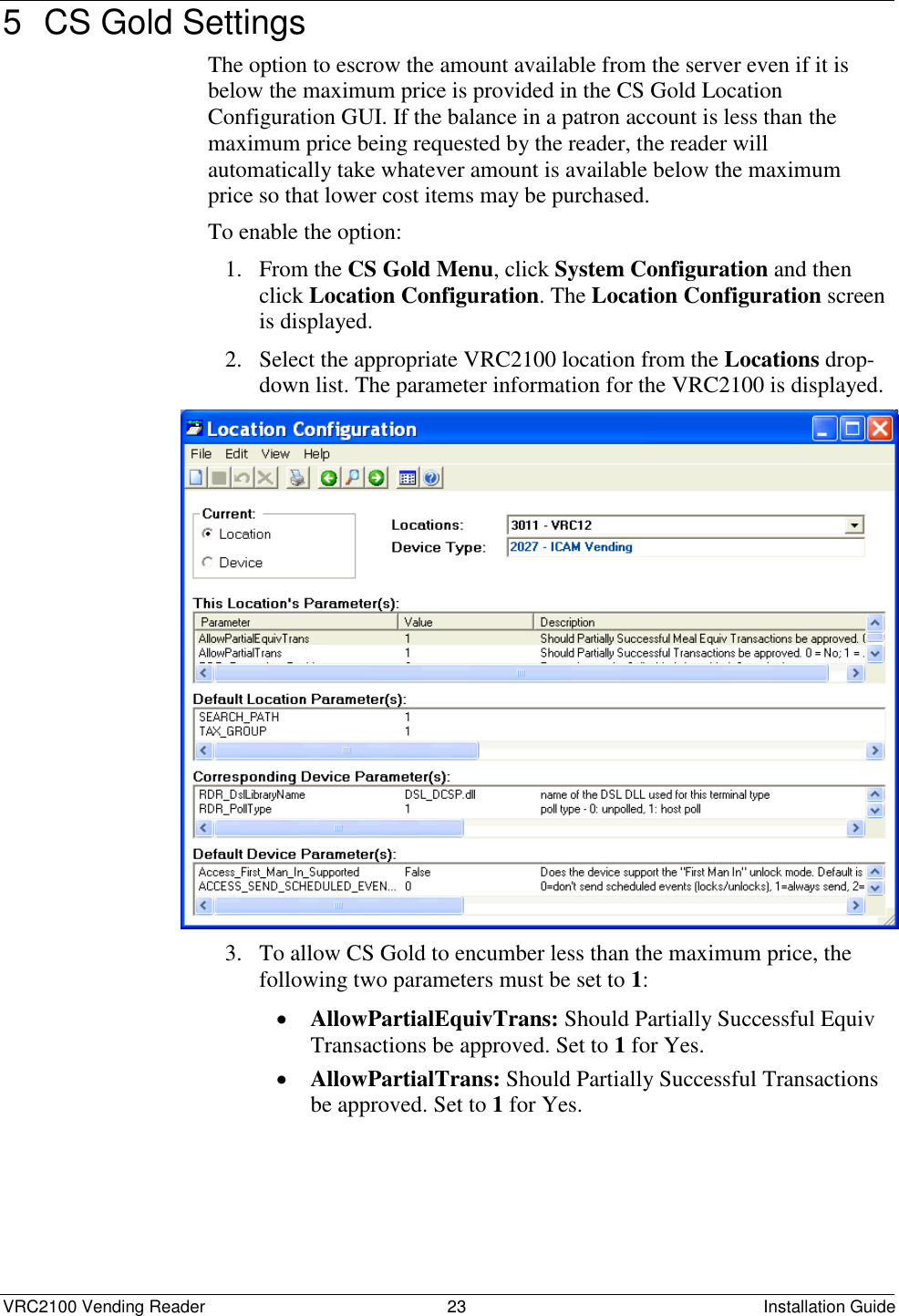
![VRC2100 Vending Reader 8 Installation Guide 7. Access the Telnet Configuration tab. After the XPORT connects to the Telnet session, a blank page will appear. Click Connect and then quickly press the [Enter] key when prompted with Press Enter for Setup Mode. For daisy-chain installations, only the Master needs these settings. The Slaves use an address in the communications packet. For Slave units, skip the Telnet settings. 8. Text will appear showing the current settings. A menu will appear at the bottom of the tab: Change Setup: 0 Server 1 Channel 1 3 E-mail 5 Expert 6 Security 7 Defaults 8 Exit without Save 9 Save and exit Your choice? 9. Select 0 Server to set the network settings for the VRC2100. The IP address is unique to each installation and requires your network administrator to assign an IP address to the VRC2100. The Gateway IP address and Netmask are also supplied by your network administrator. IP Address: Enter the IP address. Set Gateway IP Address: Enter the Gateway IP address. Netmask: Number of Bits for Host Part (0=default) (10) The network administrator will supply this number. Set DNS Server IP addr (N)? Change Telnet/Web Manager password (N)? 10. Select 1 (Channel 1) and enter the following settings: Baudrate (9600) ? I/FMode(4C)? Flow(00)? Port No (3700) ? This setting must match the Odyssey Port number in Port Setup. ConnectMode (C2) ? Send ’+++’ In Modem Mode (N) ?](https://usermanual.wiki/The-CBORD-Group/VRC2100/User-Guide-1725955-Page-12.png)
![VRC2100 Vending Reader 10 Installation Guide 3.5 Configure the XPORT for CS Gold Use the following procedure to configure the XPORT for CS Gold. Only Telnet Configuration settings are required: 1. In the Lantronix Device Installer program, access the Telnet Configuration tab. Once the XPORT connects to the Telnet session, a blank page will appear. Click Connect and then quickly press the [Enter] key when prompted with Press Enter for Setup Mode. 2. Select 0 Server and enter the following settings for CS Gold. The IP address, Gateway IP address, and Netmask must be assigned by your network administrator: IP Address: Enter the IP address. Set Gateway IP Address: Enter the Gateway IP address. Netmask: Number of Bits for Host Part (0=default) (10) Set DNS Server IP addr (N) ? Change Telnet/Web Manager password (N) ? 3. Select 1 (Channel 1) and enter the following settings for CS Gold: Baudrate (9600) ? I/FMode(4C)? Flow(00)? Port No (901) ? ConnectMode (C0) ? Send ’+++’ In Modem Mode (N) ? Show IP addr after ’RING’ (N) ? Auto increment source port (Disabled) ? Remote IP Address: Set to zero for CS Gold. Remote Port (901) ? Set to zero for CS Gold. DisConnMode (00) ? FlushMode (77) ? Pack Cntrl (00) ? DisConnTime (00:00) ? SendChar 1 (00) ? SendChar 2 (00) ? 4. Enter 9 to save your settings and exit. The XPORT will be rebooted and will start operating.](https://usermanual.wiki/The-CBORD-Group/VRC2100/User-Guide-1725955-Page-14.png)