The Genie a Division of Overhead Door GWWCP Remote Control Wall Console Transmitter for Garage Door Operator User Manual Exhibit D Users Manual per 2 1033 b3
The Genie Company a Division of Overhead Door Corporation Remote Control Wall Console Transmitter for Garage Door Operator Exhibit D Users Manual per 2 1033 b3
Exhibit D Users Manual per 2 1033 b3
WIRELESS WALL CONSOLE
Installation and Operation Instruction
39884503882, 02/2018
FCC Part 15.21 Statement:
Changes or modications not expressly approved by the party responsible for compliance could void the user’s authority to operate
the equipment.
FCC / IC Statement:
This device complies with FCC Part 15 and Industry Canada licence-exempt RSS standard(s). Operation is subject to the following two
conditions: (1) this device may not cause harmful interference, and (2) this device must accept any interference received, including
interference that may cause undesired operation of the device.
Le présent appareil est conforme aux CNR d’Industrie Canada applicables aux appareils radio exempts de licence. L’exploitation est
autorisée aux deux conditions suivantes : (1) l’appareil ne doit pas produire de brouillage, et (2) l’utilisateur de l’appareil doit accepter
tout brouillage radioélectrique subi, même si le brouillage est susceptible d’en compromettre le fonctionnement.
WARNING
!
MOVING DOOR CAN CAUSE SERIOUS INJURY OR DEATH.
•DO NOT install wall console unless the door operator’s safety device works as required by
the door operator’s manual.
•Wall Console must be mounted in sight of door, at least 5 feet above oor and clear of
moving door parts.
•Keep people clear of opening while door is moving.
•DO NOT allow children to play with the transmitter or door operator.
If safety reverse does not work properly:
•Close door then disconnect opener using the manual release handle.
•DO NOT use transmitter or door operator.
•Refer to Door and Door Opener Owner’s Manuals before attempting any repairs.
FRENCH
For questions, comments or troubleshooting, contact The Genie Company at:
1 Door Drive, Mount Hope Ohio, 44660
or call 1-800-354-3643 or visit our website at:
www.geniecompany.com
CODE
LEARN
SET
SET
OPEN
FORCE
CLOSECODE
LEARN LIMITMANUAL
Learn Button Type
Program Button Types
(All others)
PROGRAM
SET +
PROGRAM
SET +
PROGRAM
SET +
PROGRAM
SET +
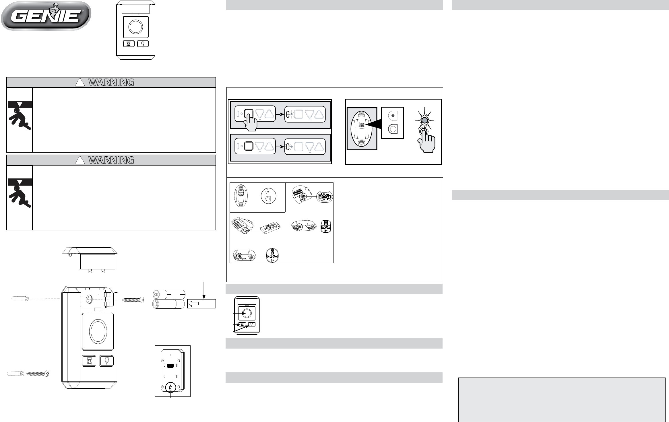
Place operator into programming mode:
Openers compatible with the
Wireless Wall Console include
one model that programs with a
LEARN BUTTON.
All other models use the
PROGRAMMING BUTTON type.
All programming button types,
although appear dierent,
program identically and are the
most common.
NOTE: Once in programming mode, you will have approximately 30 seconds to complete programming.
FIG. 1 FIG. 2
SET
SET
OPEN
FORCE
CLOSECODE
LEARN LIMITMANUAL
Learn
PRGM
FIG-A
Open cover and remove
battery tab before
programming
Lower mounting slot
AAA
NOTICE:
Door & Delay buttons operate all Genie Intellicode® openers.
Light button operates Genie Intellicode® openers produced 2013 or later.
Program Button Type Openers (See Fig. 1)
1. Press and hold the program button on the opener until the round LED turns blue, then
release.
2. The round LED will go out and the long LED will begin ashing purple. Fig. 3.
3. Press the DOOR button on the WALL CONSOLE 3 times or until door operates.
Learn Code Button Type Openers: (See Fig. 2)
1. Press and release the LEARN CODE button on the opener. Its RED LED will begin to
ash.
2. Press the DOOR button on the WALL CONSOLE 3 times or until door operates.
STEP 1) Program Wall Console to Garage Door Opener
1. DOOR Button - Runs garage door opener.
2. DELAY Button - Adds a 10+ second delay for door operation. Press the
delay button and door will automatically operate after set delay.
3. LIGHT Button - Overrides the automatic timed light function of the
garage door opener.
1
2
3
STEP 2) Operating the Door with Wall Console
AAA
Wall Consoles should be mounted at least 5 feet from oor in a convenient location within
sight of the garage door.
• Remove battery cover, battery activation tab and batteries.
Mounting to garage framing:
1. Drill a 3/32” pilot hole for the bottom mounting screw.
2. Install included screw into pilot hole, leaving 1/8” gap between the screw head and wall.
3. Hook the slotted mount on back of Wall Console over the screw.
4. Mark and drill a 3/32” pilot hole for the top screw.
5. Secure Wall Console to the wall. (Do not over-tighten).
6. Reinstall batteries and battery cover.
Mounting to drywall:
1. Drill a 3/32” pilot hole for the bottom screw insert.
2. Lightly tap drywall anchor into hole with a hammer until ush with wall.
3. Install included screw into anchor, leaving 1/8” gap between the screw head and wall.
4. Hook the slotted mount on back of Wall Console over the screw.
5. Mark position of pilot hole for the top insert and remove wall console.
6. Drill 8/38” pilot hole for top drywall anchor.
7. Lightly tap anchor into hole with a hammer until ush with wall.
8. Secure Wall Console to the wall. (Do not over-tighten).
9. Reinstall batteries and battery cover.
• WirelessWallConsolecanalsobedirectmountedtoastandardsinglegangwirebox.
(Screwsandgangboxnotincluded)
STEP 3) Mounting the Wireless Wall Console (See FIG. A)
NOTE: Any changes to the Blue LED blink rate other than the default setting will impact battery
life. Example….going to a faster rate (from once every 3 seconds to once every 2 seconds will
decrease battery life).
BLUE LED Blink rate Mode 1 (Default - Once every 3 seconds)
With only (1) AAA battery installed - hold down the DOOR button while simultaneously
installing the second AAA battery. Continue to hold the DOOR button for a total of 10
seconds until the LED ashes 3 times letting you know your selection is complete
BLUE LED Blink rate Mode 2 (Faster Blink Rate - Once every 2 seconds)
With only (1) AAA battery installed - hold down the LIGHT button while simultaneously
installing the second AAA battery. Continue to hold the LIGHT button for a total of 10
seconds until the LED ashes 3 times letting you know your selection is complete.
BLUE LED Blink rate Mode 3 (Blue LED OFF - Maximum Battery Life)
With only (1) AAA battery installed - hold down the DELAY button while simultaneously
installing the second AAA battery. Continue to hold the DELAY button for a total of 10
seconds until the LED ashes 3 times letting you know your selection is complete.
Changing LED Blink Rates
Mounting
Screws
Drywall
Anchors
-OR-
The default delay period is set for a 10 second delay. Once the DELAY button has been
pressed the operation can’t be canceled unless the same console DOOR button is pressed.
During the activation of a delay operation consecutive button presses will add 10 seconds
to the delay time. Up to 3 consecutive button presses for a total of 30 seconds can be
made. At any point in time during a delay operation, a DOOR button press will disable the
current delay operation
Delay Feature:
The Wireless Wall Console includes self diagnostic LEDs
1. LED Blue Blink = Indicates NORMAL status.
2. LED Red Blink = Indicates low battery.
Wireless Wall Console LED Signals:
-OR-