Contents
- 1. Manual
- 2. Manual Host
- 3. Manual RF Module
Manual
V0.5|7/2017
Installation guides available online @ www.awti.com 1 | P a g e
Installation Instructions
3EC With External Cam & Viewing Monitor Installation
Required Tools……………………...pg.1
Hardware……………………………. pg.1
Pre-Installation Checklist………... pg.2
Safety Information……………....... pg.2
Installation Diagrams……………...pg.2,3
Location Recommendations……..pg.3,4
Installation Instructions…………..pg.5,6,7,8
Wiring Connection/Descriptions…pg.8,9
Component Connection……………pg.10
Required Tools
Drill (Cordless)
Wire Strippers
Crimper Plier
Driving Bit Set
Magnetic Drive Guide
Burr Tool
Step Drill Bits (3/16 in.-7/8 In.)
Digital Multimeter
Plastic Antenna Tool
Panel Popper
End Wire Brush (3/4 In.)
Magnetic Tray
Additional Items (optional)
Wire Connectors
Zip Ties
Wire (18 Gauge)
Grease Marker
Tamper Seal
Alcohol Wipes
Replacement Fuses (5,10,15,20 amp)
Star Washers
Self-Tapping Screws
Hardware
UDU
WU
Power Cable
HDMI
DVI Cable
Expansion
Event Button
10 ft. Extension
AV Splitter Cable
External Cam & Monitor
Antenna (MA240.LBI.012) [Length=15feet]
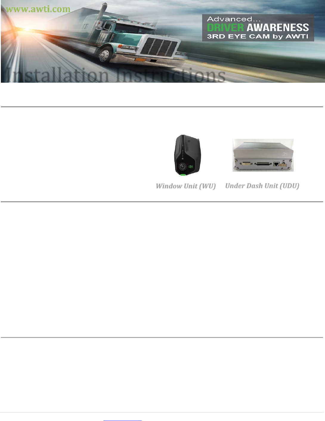
Under Dash Unit (UDU)
Window Unit (WU)

Installation guides available online @ www.awti.com 2 | P a g e
FCC Caution:
FCC Compliance statements:
This equipment complies with Part 15 of the FCC Rules.
Operation is subject to the following two conditions: (1) this device may not cause harmful interference, and
(2) this device must accept any interference received, including interference that may cause undesired operation.
CAUTION:
The changes or modifications not expressly approved by the party responsible for Compliance could void the user’s
authority to operate the equipment and The antennas for this transmitter must be installed to provide a separation
distance of 20cm from all persons and must not be co-located or operating in conjunction with any other antenna or
transmitter.
Canadian Notice:
IC Compliance statements:
This device complies with Industry Canada license-exempt RSS standard(s). Operation is subject to the
following two conditions: (1) this device may not cause interference, and (2) this device must accept any
interference, including interference that may cause undesired operation of the device.
This equipment complies with radio frequency exposure limits set forth by Industry Canada for an uncontrolled
environment. This equipment should be installed and operated with minimum distance 20cm between the
device and the user or bystanders.
CAUTION:
Any changes or modifications not expressly approved by the party responsible for compliance could void the user’s
authority to operate the equipment.
Déclarations de conformité IC:
Cet appareil est conforme aux normes RSS exonérées de licence d'Industrie Canada. L'opération est soumise à En suivant
deux conditions: (1) cet appareil ne doit pas provoquer d'interférence, et (2) cet appareil doit accepter tout Les
interférences, y compris les interférences susceptibles de provoquer un fonctionnement indésirable de l'appareil.
Cet équipement est conforme aux limites d'exposition aux fréquences radio établies par Industrie Canada pour une
incontrôlée environnement. Cet équipement doit être installé et utilisé avec une distance minimale de 20 cm entre le
L'appareil et l'utilisateur ou les spectateurs.
ATTENTION:
Toute modification ou modification non expressément approuvée par la partie responsable de la conformité pourrait
annuler l'autorisation de l'utilisateur d'utiliser l'équipement.
Antenna must be mounted on glass surface only for the compliance with FCC and IC standards.
Installation on a different surface is prohibited.
L'antenne doit être montée sur la surface de verre uniquement pour la conformité aux FCC et IC
normes. L'installation sur une surface différente est interdite.
Installation guides available online @ www.awti.com 3 | P a g e
Pre-installation Checklist:
The 3rd Eye Cam is programmed by serial number/mac address to a specific vehicle. Prior to installation, the
following steps should be taken for proper documentation of equipment.
1. Open the box with a 3rd Eye Cam kit.
2. Gather all necessary hardware listed above.
3. Take photo of vehicle ID #, it will be located on the chassis as well as body of the vehicle.
4. Record Vehicle body or truck ID number and Vehicle Identification Number (VIN)
5. Record installer name
Safety Information
The 3rd Eye Cam installation requires attentiveness. Please be sure to abide by the following guidelines.
Failure to do so may result in property damage and or personal injury.
Precaution prior to installation of the 3rd Eye Cam system:
1. Turn off the engine before installing the system.
2. Remove all power to all areas where wires will be connected.
3. Install the product in a location where Wi-Fi and GPS signals can transmit effectively (not blocked by
solid material other than windshield glass).
4. Before permanently mounting the camera, make sure the camera interior view is not blocked by the
rearview mirror or other objects located inside vehicle.
5. The customer must approve the camera mounting location.
6. The unit must be installed level both horizontally and vertically for best results.
7. The on-site mechanic or vehicle manufacturer must approve wiring connections.
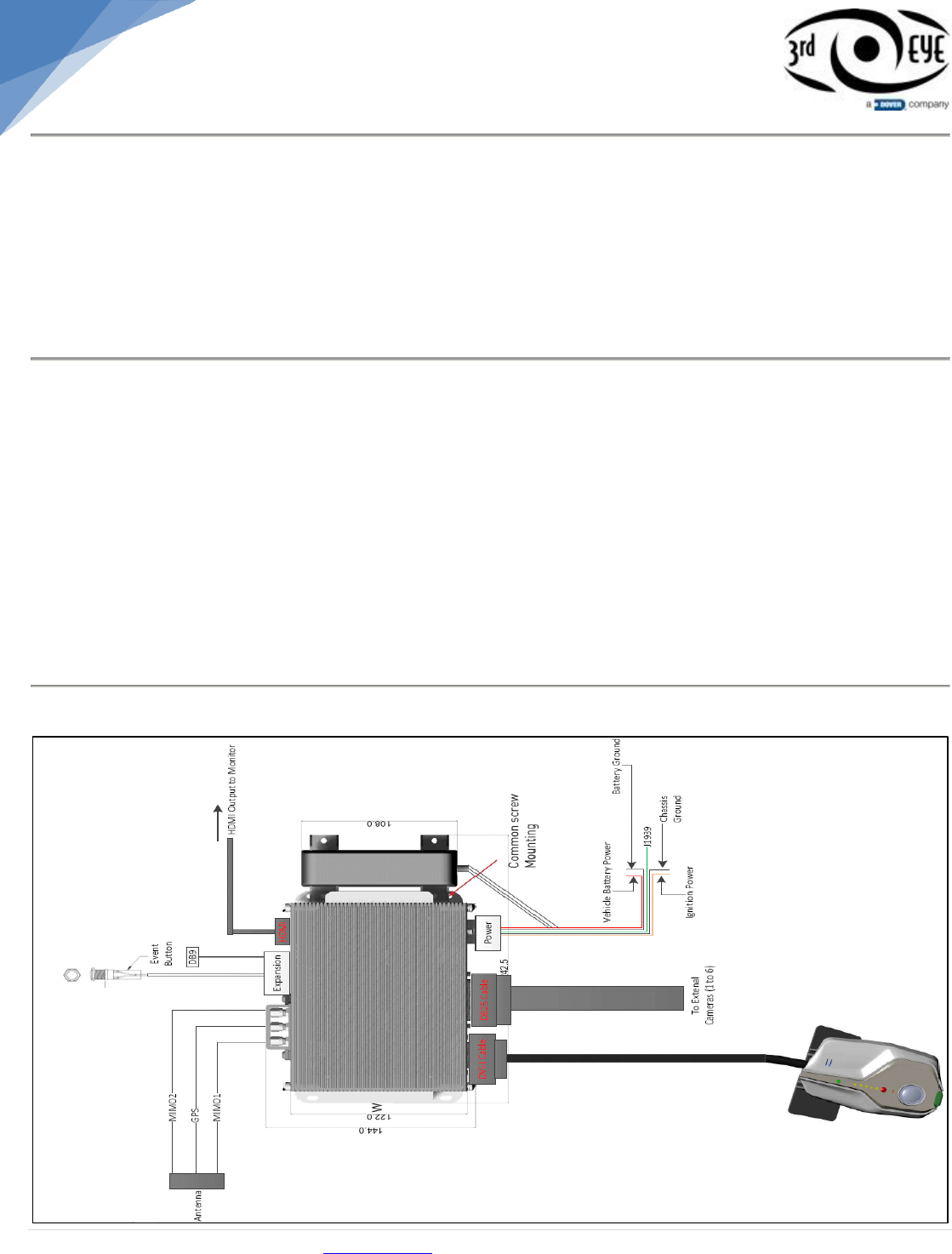
Installation Diagrams
DS3 Diagram
Installation guides available online @ www.awti.com 4 | P a g e
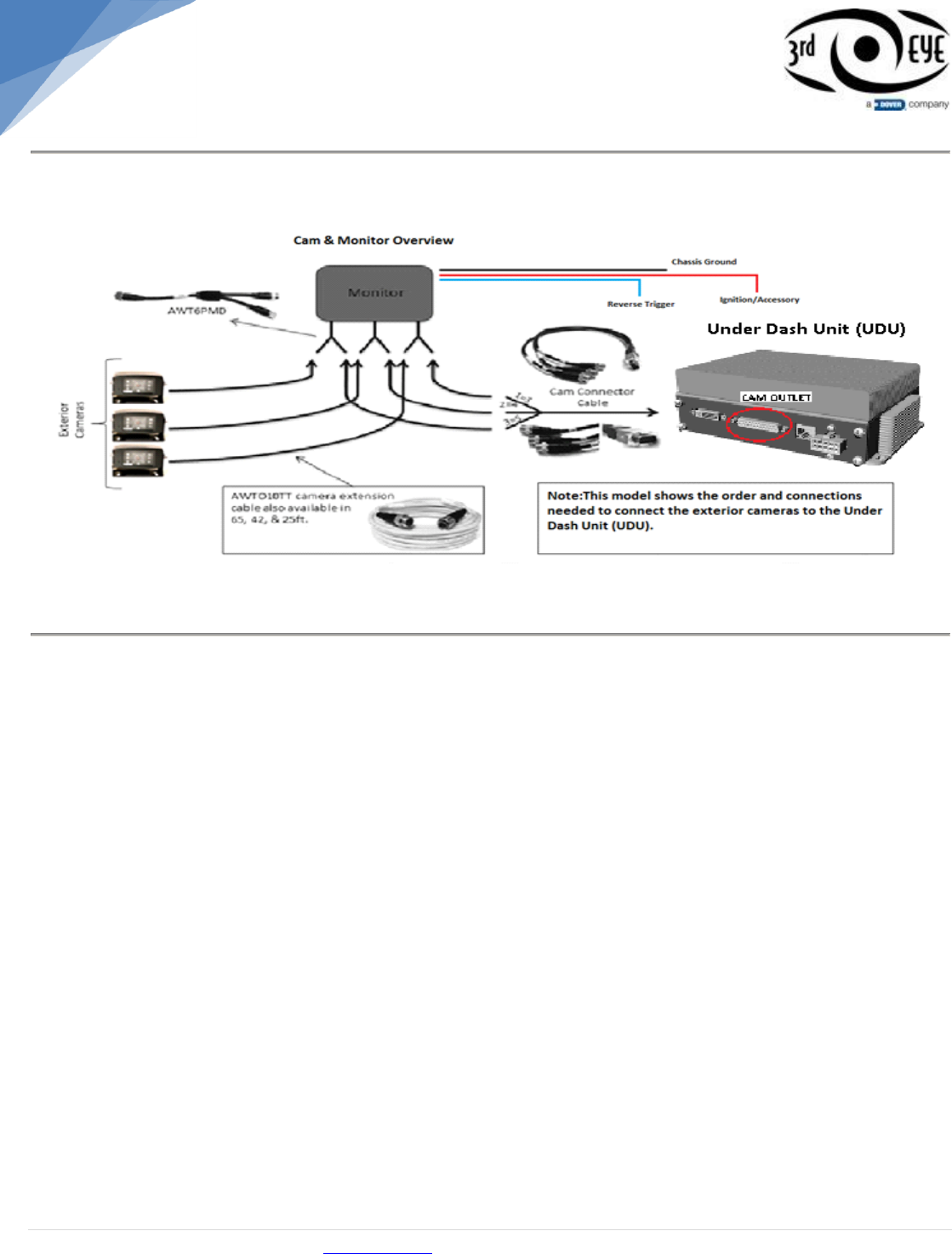
Cam/Monitor Diagram
Location Recommendations
Installing the Under Dash Unit
The UDU (under dash unit) can be mounted in various places inside the cab such as, under the
cabs bench seating, in the overhead compartment above the windshield, in the console, or
under the vehicles dash.
UDU under bench seating
With a step drill bit, drill a hole into the back of the bench base so that wires may be run directly
to the UDU. Tip: Always check your surroundings and look twice then drill once.
Use a burr tool or insert a rubber grommet into the hole so that the edges will not remain sharp.
Feed all wire connections to the UDU under the floor side paneling leading to the back of the
bench seat where the drill hole is located.
Connect all necessary cabling and mount the UDU to the floorboard under the bench seat.
Position of antenna should be high on the windshield surface.
UDU in overhead compartment
Disassemble panel between the headliner and windshield.
Feed cabling through the “A” pillar between the windshield and the door.
Using a step drill, drill a hole and insert a rubber grommet in the corner of the overhead unit
between the windshield and side paneling.
Feed cabling through the hole and make all necessary connections to the UDU.
Be sure to mount the UDU so that it is secure against the head compartment.
Position of antenna should be high on the windshield surface.
Installation guides available online @ www.awti.com 5 | P a g e
UDU in “Dog House” center console
Disassemble the middle paneling that contains controls (i.e. parking brake).
Run all cabling from under the dash through the bottom of the center console.
Make all necessary connections to the UDU.
When installing the UDU under the console, it is not crucial to have a completely secure mount.
Attempt to find an area within the console where either one screw can mount the UDU or can be
zip tied to an existing brace.
Position of antenna should be high on the windshield surface.
UDU under the vehicles dash
Locate an area under the dash were the UDU can be securely mounted. Tip: Often the best
place for this is on the driver’s side behind the axel of the steering wheel near the J-1939 factory
outlet.
After making all connections securely mount the UDU so that it is flush against the under dash
wall.
Position of antenna should be high on the windshield surface.
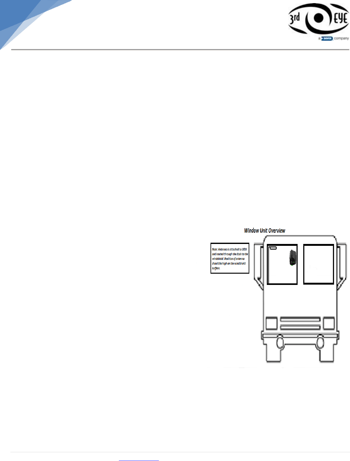
Installing the Window Unit WU Diagram
The window unit must be mounted in a
location that provides an unobstructed
view of the interior and exterior (front) of
the vehicle.
Verify that the placement does not block
the driver’s primary field of view.
The camera lens facing the interior
should capture an internal view from the
outside shoulder of the driver to the
outside shoulder of a front-seat
passenger.
Sedans, pickups, and light-duty trucks
usually have a traditional rear-view
mirror. Position the window unit so that
the outer ring of the camera lens is
visible when the mirror is adjusted to its
lowest position. Remember that the
mirror usually pivots on two points: one
on the glass and one on the back of the mirror.
Buses and large trucks often have nonstandard windshields and mirrors. Choosing a location
too high on the windshield can keep the driver out of view, cause a loss of vision in front of the
vehicle, and push the unit’s accelerometers further away from the vehicle’s center of mass.
Look for potential obstructions such as windshield wipers, tinted window, sun visors, circulation
fans, and the rear-view mirror itself when it is in its lowest position. Aftermarket window tint may
not support the weight of the 3rd Eye unit and may result in separation from the glass.
Position of the antenna should be high on the windshield surface.

Installation guides available online @ www.awti.com 6 | P a g e
Installation Instructions
This section provides installation instructions to 3rd Eye Cam, along with operation verification.
1. Disassembling Side Floorboard Paneling
The vehicles side floorboard panels need to be disassembled in order to gain easy access to needed
areas during the installation.
Using a cordless drill, disassemble both the driver and passenger side floorboard panels.
Place paneling and screws in magnetic tray for reassembling.
2. Disassembling the Dash Board
The vehicles dashboard needs to be disassembled in order to prepare for wiring of the Under Dash Unit
(UDU) installation.
Using a cordless drill disassemble the dashboard along with any plating to allow for complete
access.
Place all dashboard parts and screws in a safe place for reassembling.
3. Disassembling Button Paneling
The button paneling is located under the dashboard in the center of the cab.
Remove parking brake and place in magnetic tray to reattach later.
Carefully remove all screws in order to take off paneling using an electric drill.
Once all screws have been removed, pull paneling away from dash and let it hang in a relaxed
position to prevent any strain on the existing wiring.
4. Event Button
Finding a suitable event button location.
The button paneling that has been detached from the vehicles dashboard is where the Red Event
Button is recommended to be installed.
Choose a spot on the vehicles button paneling where the driver will have easy access to the panic
button in case of emergency.
Using a Step Drill create a 5/8” hole in the spot you have chosen for the event button.
The event button that has been provided with the system contains black and red wiring.
Take the end of the cable that is not attached to the panic button and feed it through the 5/8”hole.
Once the wire has been fed all the way through the hole, the face of the red button should be able to
fit flush against the front face of the dash.
Now that the button is ready to be secured against the dash panel, locate the (spec.) washer and
(spec.) nut for the panic button.
Starting at the end of the wire, slide the (spec.) washer with the (spec.) nut through to the back of
the button.
Once the two pieces have reached the back side of the event button behind the dash paneling
rotate the (spec.) nut and (spec.) washer clockwise until both are firmly flush against the back of the
button paneling.
The event button should now be securely in place on the dash panel.
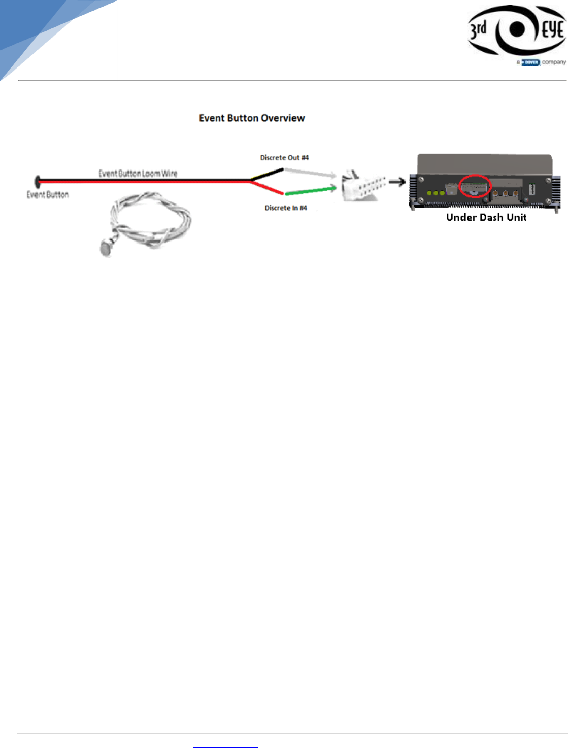
Locate expansion cable.
Connect red and black wires on event button to green and white wires (Discrete Input 4) on the
expansion cable. (See below image).
Installation guides available online @ www.awti.com 7 | P a g e
Event Button Diagram
5. Connecting 3rd Eye Cam Window Unit
DVI Cable Connection
Locate the hinge door on the top side of the window unit which contains the HDMI connection.
Insert the HDMI cable into the top of the window unit until it is plugged into the outlet.
Connecting the HDMI to the WU (widow unit) socket may be difficult at times. Be sure not to put too
much force on the connection to avoid damaging the socket.
Close the hinge door to secure the HDMI connection.
Match the security screw that is attached to the door hinge with the pre-made hole that is directly
below the hinge.
Use the appropriate spanner drive to fasten the U-screw into the threaded hole. Do not over tighten.
6. Mounting Window Unit
Once an area for mounting has been chosen, clean desired area with alcohol wipes and allow to
dry for proper adhesion of the window unit bracket.
Once area is dry, slowly peel away the plastic lining protecting the adhesive on the back of the
window unit bracket.
The camera’s position must be vertical and pointing straight back.
Apply window unit to glass and continue applying pressure for a minimum of 30 seconds for proper
adhesion to the glass.
Once the Window Unit has been mounted, mount the antennas. The antenna needs to be mounted
one on either side of the windshield as high on the glass as possible for minimal interference.
7. Connecting Window Unit to UDU
After attaching the 3rd Eye Cam to the windshield be sure to hide any extra wire that may obstruct
the view of the driver and window unit.
If extra wire length is present, loop excess wire in small 4” diameter loops and zip tie together.
Slightly pull the edge of the interior headliner down and insert the excess wire.
Insert the DVI cable into headliner and run it across the edge until it reaches the “A” pillars.
Disassemble the desired “A” pillar paneling and run DVI cable behind it.
Disassemble the desired kick panel if needed to route DVI cable (depending on UDU location).
Run the DVI cable behind all the paneling guiding it to the Under Dash Unit.
Insert the DVI cable with UDU outlet using mounting screws on DVI cable overmold.
Installation guides available online @ www.awti.com 8 | P a g e
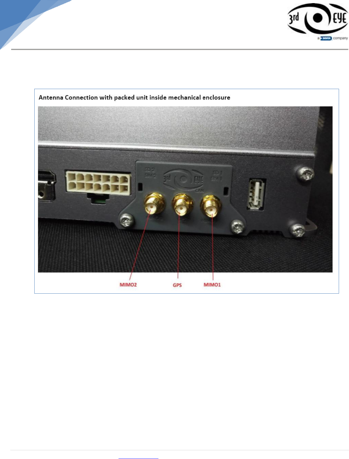
8. Connecting Antenna to UDU
After attaching antenna to appropriate position on Windshield, connect 15 feet long antenna cable with
UDU as per instruction below:
As shown in above image,
o Connect antenna MIMO1 cable with MIMO1 location (Transmit Port) indicated on antenna door
o Connect antenna MIMO2 cable with MIMO2 location (Rx Diversity Port) indicated on antenna
door
o Connect GPS cable with GPS location indicated on antenna door
Installation guides available online @ www.awti.com 9 | P a g e
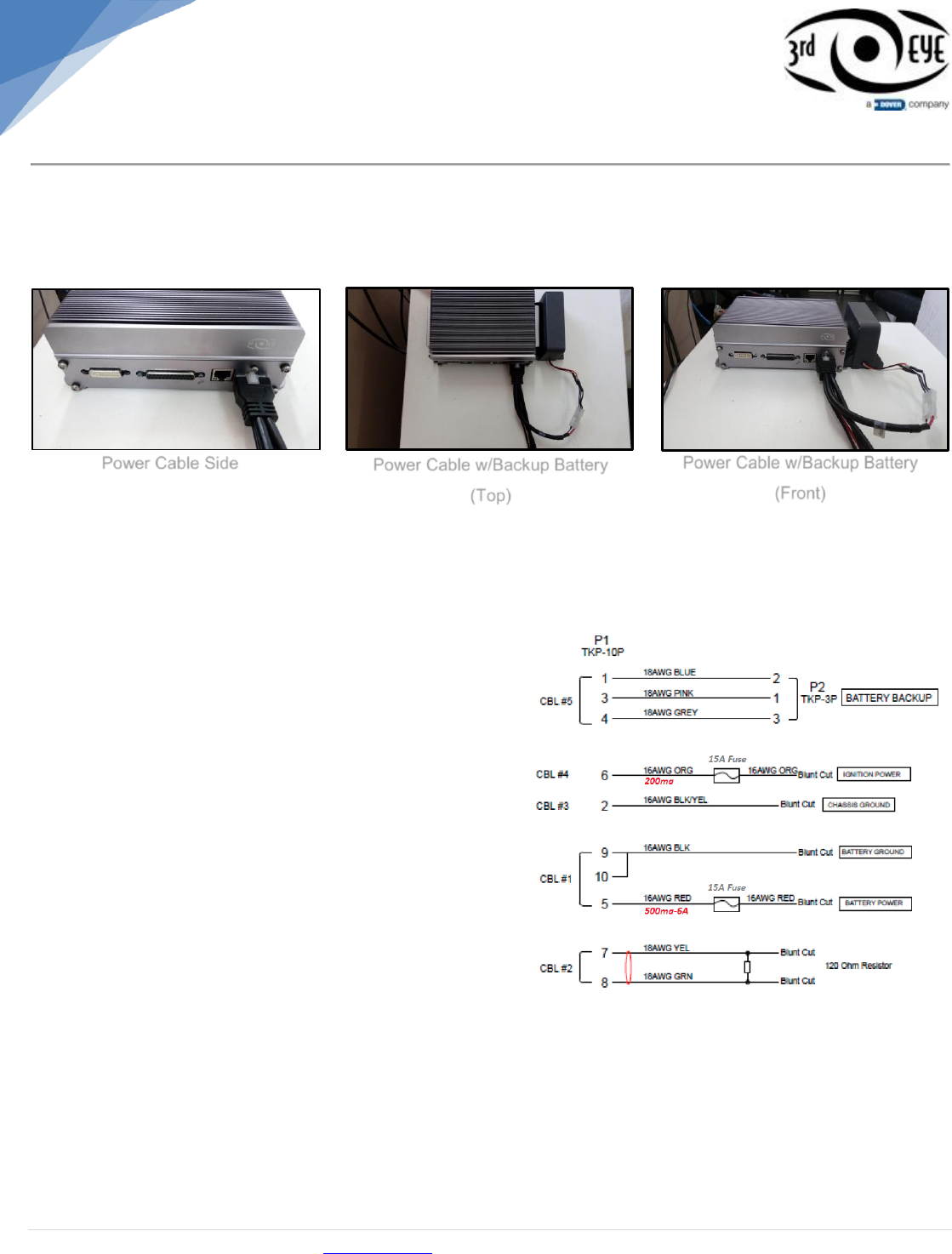
9. Connecting to Power Source
The V3 requires the new power board in order to provide “clean power” for optimum performance.
Connect the power cable to the input side of the power board unit and connect the jumper cable to the
output of the power board directly to the UDU.
The power wires consist of multiple intertwined wires that are individually colored red, black,
black/yellow and orange. Connector P2 (see below) with wire colors blue, pink and grey are for the
battery backup system (not supplied/optional).
Color Code Diagram
In order to reach a power source these wires
need to reach from the UDU to the exterior of
the truck where the battery is located.
Note: To make it easier while maneuvering the
wires through the dash do not separate the
wires from one another.
Starting with the bare wire ends insert the wires
below the dash on desired side
(passenger/driver). Tip: Applying electrical tape
near the end of the wires makes it easier to
keep them all together while maneuvering
through the dash.
Once the wires are near either kick panel look
for a point of entry, preferably with a rubber
grommet, leading to the exterior of the vehicle.
If no grommet is present, find a discrete location away from other major wiring or mechanical
components to drill a pass through whole. Tip: Remember to look twice and drill once before drilling
into any surface to avoid property damage or personal injury.
Once a hole has been made, use burr tool to eliminate any sharp edges and insert rubber grommet.
Feed the wires through the opening. Note: Leave black/yellow, orange, and green/yellow braided
wires leading into the interior of the vehicle.
Once wires have been passed through, locate the wires on the exterior of vehicle.
Without losing the ability to connect the other end to the UDU gain a comfortable amount of slack so
the wires can be worked on.
Power Cable Side
Power Cable w/Backup Battery
(Front)
Power Cable w/Backup Battery
(Top)

Installation guides available online @ www.awti.com 10 | P a g e
Begin unbraiding the wires from one another while keeping them intertwined in the cab.
Now that the wires are individualized outside the cab into three separate red, black, and orange
wires add appropriate diameter wire loom to each pair.
This wire loom should start from the point of wire separation up to 3 to 4 inches from end.
Be sure to wrap all the wire loom ends to the wire with electrical tape to avoid displacement.
Wiring Connection/Descriptions
Note: Wires are in order of required connection.
Black/Yellow Wire
The black/yellow wire needs to be connected to the chassis ground.
Locate black/yellow wire in interior of vehicle. (wire end was left in interior)
Since chassis ground is susceptible to corrosion from exterior elements, it is best to find chassis
ground on interior of vehicle.
Locate an empty area of chassis. The wire can be grounded to several parts of the vehicle as long
as it is mounted to a large all metal part. The vehicles frame, firewall, or chassis are all appropriate
places for grounding.
Verify that there are no moving components or electrical wiring on either side.
If all is clear, using an end wire brush, strip desired grounding point of paint or oxidation.
Using the appropriate ring terminals, crimp a ring terminal to the end of the wire.
Using a self-tapping screw and star washers ground ring terminal to chassis. Note: When
grounding, use a star washer below the ring terminal. Doing this will provide multiple grounding
points instead of a single point in case oxidation ever does become an issue.
Black Wire
The black wire needs to be connected to battery ground because electrical currents will leak into a non-
insulated metal part of the vehicle and cause a serious electrical shock.
Remove the negative battery post clamp.
Using the appropriate ring terminals, crimp a ring terminal to the end of the wire and attach securely
to the battery post clamp.
Re-connect the positive clamp to the positive post.
Secure wire to existing positive wire with a zip tie to avoid movement and possible loose
connections in the future.
Orange Wire
The orange wire power needs to be connected to a true ignition source in the vehicle along with an
inline fuse leading to the UDU.
Locate the orange wire in interior of vehicle.
Using a digital multimeter locate a true ignition source. Tip: The steering column will be the easiest
place to find a true ignition.
Warning: A digital multimeter is the ONLY appropriate tool for testing wires in any vehicle.
Test lights and or test probes are prohibited.
Failure to use a digital multimeter can cause extensive damage to the onboard computers in a
vehicle and or cause personal injury.
Installation guides available online @ www.awti.com 11 | P a g e
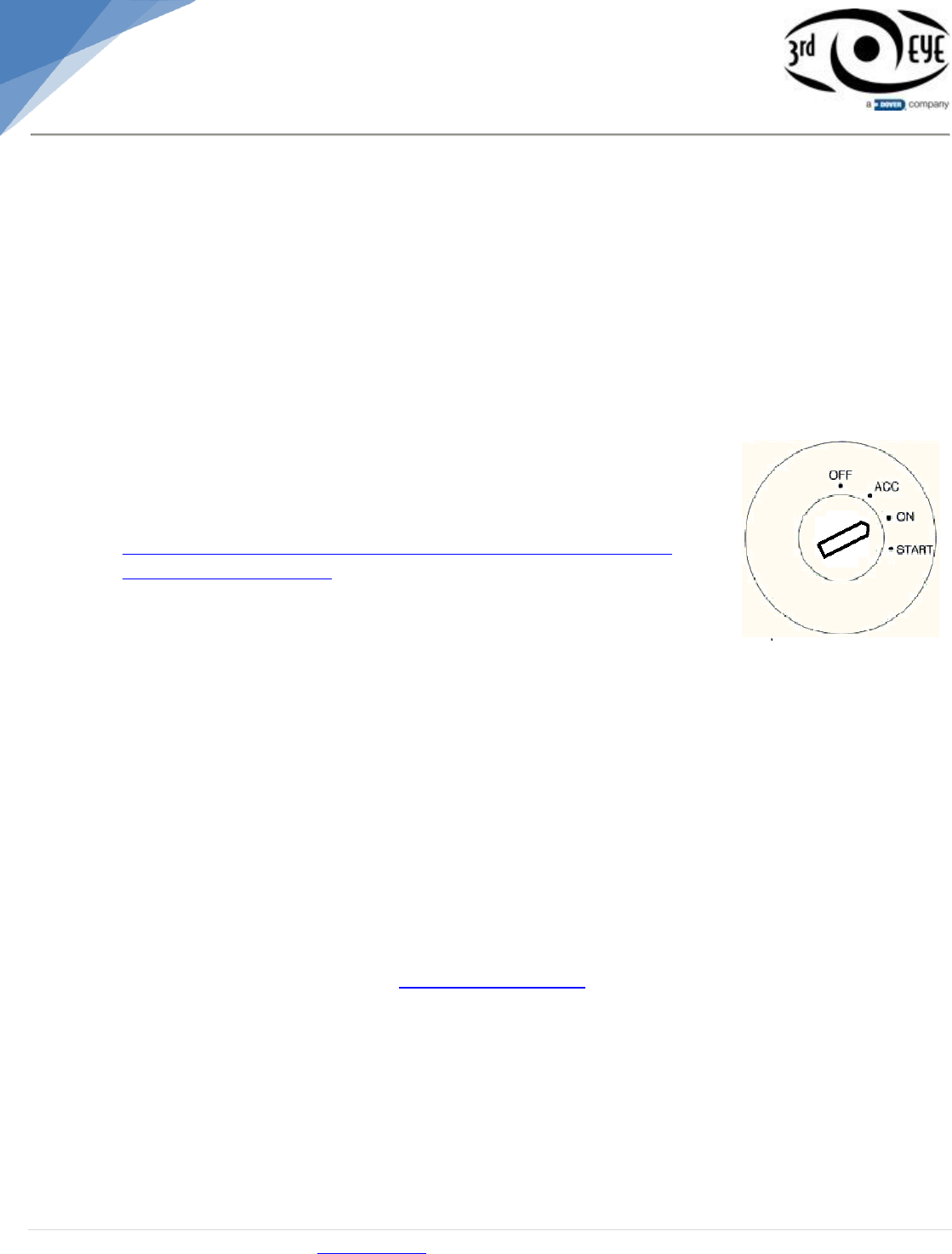
Note: A true ignition source will only show 12v when the key is in the ACC and ON position. 12v will
not be present when the vehicle is cranking.
Using the appropriate size wire tap, install the wire tap to end of orange wire.
Tap the orange wire to the ignition wire that was located.
3 to 4 inches away from the end of orange wire place a zip tie and fasten to existing vehicle harness
to avoid movement and possible loose connections in the future.
Red Wire
The red power wire needs to be connected directly to the battery of the vehicle in order for the 3rd Eye
Unit to maintain a constant 12v source.
Remove the positive battery post clamp.
Using the appropriate ring terminals, crimp a ring terminal to the end of the wire and attach securely
to the battery post clamp.
Re-connect the positive clamp to the positive post.
Secure the wire to an existing positive wire with a zip tie to avoid movement and possible loose
connections in the future.
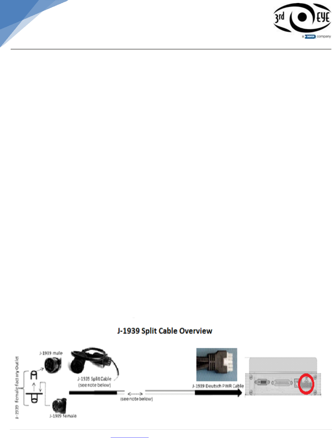
Green & Yellow Wires 9’
Locate the green and yellow braided wires (J1939 Data) on power cable.
Locate the J-1939 Y-Splitter. (See below)
Connect the vehicles J-1939 connector to the stem of the J-1939 Y Splitter. (This is usually in the
upper “dog house” center console area).
There will be a dead end terminating resistor. Unplug the terminating resistor and install the
3EC1939Y-M1 or 3EC1939Y-AUTOCAR cable.
Install the terminating resistor back into the 1939Y cable.
Connect the green & yellow wires from power cable to the green and yellow wires on the J1939-Y
Splitter (color to color) using appropriate connectors.
Once connections have been made, do a “U” loop on the green and yellow wires and zip tie both
ends to give the wires stress relief to avoid movement and possible loose connections in the future.
J1939 Diagram
Installation guides available online @ www.awti.com 12 | P a g e
Component Connection
At this point of the installation all components have been mounted and wire connections made.
Next, connect all the components to the UDU in the following order.
o Expansion
o AV Splitter Cable
o HDMI to Monitor
o DVI to WU
o Power Cable
Locate the disconnect switch on the exterior of vehicle (normally near battery)
Turn disconnect switch to ON position.
Turn ignition to ON and RUNNING position.
The 3rd Eye unit normally takes 45-90 seconds to boot up from a “cold
boot”. Allow this amount of time to generate a 3G lock “solid orange”
and GPS lock “solid green”
Once locks are generated, visit
http://awti.3rdeyecam.com/tem/installer/search?t=1da77663-a9b5-
46ae-8cae-f01519d4d67f from your mobile device and follow the steps
provided in the Micro-Site Guide.
Once all the steps have been followed call the
3rd Eye Hotline @ (281) 977-0858 to receive the final “All Systems Up”
confirmation.
Once confirmation has been received, all the panels in the vehicle can be reassembled.
Installation Completion
Complete a vehicle walk-through to make sure all panels have been reassembled correctly.
Check for any loose or extra screws.
Make sure no tools have been left behind.
Make sure all notes and pictures of the install have been uploaded to the micro-site before exiting
vehicle.
This 3rd Eye Cam equipped vehicle is now ready for monitoring.
Additional Information
3rd Eye Cam support is available 24 hours/7 days @ (281) 977-0858 for any 3rd Eye related product
needs. You can also reach us @ drivesupport@awti.net
End of Document