The Loln Electric LEWB0000111 Power Wave Communication Kit User Manual IM10421 Power Wave R450
The Lincoln Electric Company Power Wave Communication Kit IM10421 Power Wave R450
User Manual
Operator’s Manual
POWER WAVE ®R450
Register your machine:
www.lincolnelectric.com/register
Authorized Service and Distributor Locator:
www.lincolnelectric.com/locator
IM10421 | Issue D ate July-17
© Lincoln Global, Inc. All Rights Reserved.
For use with machines having Code Numbers:
12644, 12645, 12712, 12713,
12714, 12715
Need Help? Call 1.888.935.3877
to talk to a Service Representative
Hours of Operation:
8:00 AM to 6:00 PM (ET) Mon. thru Fri.
After hours?
Use “Ask the Experts” at lincolnelectric.com
A Lincoln Service Representative will contact you
no later than the following business day.
For Service outside the USA:
Email: globalservice@lincolnelectric.com
Save for future reference
Date Purchased
Code: (ex: 10859)
Serial: (ex: U1060512345)
THANK YOU FOR SELECTING
A QUALITY PRODUCT BY
LINCOLN ELEC TRIC.
PLEASE EXAMINE CARTON AND EQUIPMENT FOR
DAMAGE IMMEDIATELY
When this equipment is shipped, title passes to the purchaser
upon receipt by the carrier. Consequently, claims for material
damaged in shipment must be made by the purchaser against the
transportation company at the time the shipment is received.
SAFETY DEPENDS ON YOU
Lincoln arc welding and cutting equipment is designed and built
with safety in mind. However, your overall safety can be increased
by proper installation ... and thoughtful operation on your part.
DO NOT INSTALL, OPERATE OR REPAIR THIS EQUIPMENT
WITHOUT READING THIS MANUAL AND THE SAFETY
PRECAUTIONS CONTAINED THROUGHOUT. And, most importantly,
think before you act and be careful.
This statement appears where the information must be followed
exactly to avoid serious personal injury or loss of life.
This statement appears where the information must be followed
to avoid minor personal injury or damage to this equipment.
KEEP YOUR HEAD OUT OF THE FUMES.
DON’T get too close to the arc.
Use corrective lenses if necessary
to stay a reasonable distance
away from the arc.
READ and obey the Safety Data
Sheet (SDS) and the warning label
that appears on all containers of
welding materials.
USE ENOUGH VENTILATION or
exhaust at the arc, or both, to
keep the fumes and gases from
your breathing zone and the general area.
IN A LARGE ROOM OR OUTDOORS, natural ventilation may be
adequate if you keep your head out of the fumes (See below).
USE NATURAL DRAFTS or fans to keep the fumes away
from your face.
If you de velop unusual symptoms, see your supervisor.
Perhaps the welding atmosphere and ventilation system
should be checked.
WEAR CORRECT EYE, EAR &
BODY PROTECTION
PROTECT your eyes and face with welding helmet
properly fitted and with proper grade of filter plate
(See ANSI Z49.1).
PROTECT your body from welding spatter and arc
flash with protective clothing including woolen
clothing, flame-proof apron and gloves, leather
leggings, and high boots.
PROTECT others from splatter, flash, and glare
with protective screens or barriers.
IN SOME AREAS, protection from noise may be appropriate.
BE SURE protective equipment is in good condition.
Also, wear safety glasses in work area
AT ALL TIMES.
SPECIAL SITUATIONS
DO NOT WELD OR CUT containers or materials which previously
had been in contact with hazardous substances unless they are
properly cleaned. This is extremely dangerous.
DO NOT WELD OR CUT painted or plated parts unless special
precautions with ventilation have been taken. They can release
highly toxic fumes or gases.
Additional precautionary measures
PROTECT compressed gas cylinders from excessive heat,
mechanical shocks, and arcs; fasten cylinders so they cannot fall.
BE SURE cylinders are never grounded or part of an
electrical circuit.
REMOVE all potential fire hazards from welding area.
ALWAYS HAVE FIRE FIGHTING EQUIPMENT READY FOR
IMMEDIATE USE AND KNOW HOW TO USE IT.
WARNING
CAUTION
Safety 01 of 04 - 06/15/2016
SECTION A:
WARNINGS
CALIFORNIA PROPOSITION 65 WARNINGS
Diesel Engines
Diesel engine exhaust and some of its constituents are known
to the State of California to cause cancer, birth defects, and other
reproductive harm.
Gasoline Engines
The engine exhaust from this product contains chemicals known
to the State of California to cause cancer, birth defects, or other
reproductive harm.
ARC WELDING CAN BE HAZARDOUS. PROTECT
YOURSELF AND OTHERS FROM POSSIBLE SERIOUS
INJURY OR DEATH. KEEP CHILDREN AWAY.
PACEMAKER WEARERS SHOULD CONSULT WITH
THEIR DOCTOR BEFORE OPERATING.
Read and understand the following safety highlights. For
additional safety information, it is strongly recommended
that you purchase a copy of “Safety in Welding & Cutting -
ANSI Standard Z49.1” from the American Welding Society,
P.O. Box 351040, Miami, Florida 33135 or CSA Standard
W117.2-1974. A Free copy of “Arc Welding Safety” booklet
E205 is available from the Lincoln Electric Company,
22801 St. Clair Avenue, Cleveland, Ohio 44117-1199.
BE SURE THAT ALL INSTALLATION, OPERATION,
MAINTENANCE AND REPAIR PROCEDURES ARE
PERFORMED ONLY BY QUALIFIED INDIVIDUALS.
FOR ENGINE POWERED
EQUIPMENT.
1.a. Turn the engine off before troubleshooting
and maintenance work unless the
maintenance work requires it to be running.
1.b. Operate engines in open, well-ventilated
areas or vent the engine exhaust fumes outdoors.
1.c. Do not add the fuel near an open flame
welding arc or when the engine is running.
Stop the engine and allow it to cool before
refueling to prevent spilled fuel from
vaporizing on contact with hot engine parts
and igniting. Do not spill fuel when filling
tank. If fuel is spilled, wipe it up and do not start engine until
fumes have been eliminated.
1.d. Keep all equipment safety guards, covers
and devices in position and in good repair.
Keep hands, hair, clothing and tools away
from V-belts, gears, fans and all other
moving parts when starting, operating or
repairing equipment.
1.e. In some cases it may be necessary to remove safety guards to
perform required maintenance. Remove guards only when
necessary and replace them when the maintenance requiring
their removal is complete. Always use the greatest care when
working near moving parts.
1.f. Do not put your hands near the engine fan. Do not attempt to
override the governor or idler by pushing on the throttle control
rods while the engine is running.
1.g. To prevent accidentally starting gasoline engines while turning
the engine or welding generator during maintenance work,
disconnect the spark plug wires, distributor cap or magneto wire
as appropriate.
1.h. To avoid scalding, do not remove the radiator
pressure cap when the engine is hot.
ELECTRIC AND
MAGNETIC FIELDS MAY
BE DANGEROUS
2.a. Electric current flowing through any conductor
causes localized Electric and Magnetic Fields (EMF).
Welding current creates EMF fields around welding cables
and welding machines
2.b. EMF fields may interfere with some pacemakers, and
welders having a pacemaker should consult their physician
before welding.
2.c. Exposure to EMF fields in welding may have other health effects
which are now not known.
2.d. All welders should use the following procedures in order to
minimize exposure to EMF fields from the welding circuit:
2.d.1. Route the electrode and work cables together - Secure
them with tape when possible.
2.d.2. Never coil the electrode lead around your body.
2.d.3. Do not place your body between the electrode and work
cables. If the electrode cable is on your right side, the
work cable should also be on your right side.
2.d.4. Connect the work cable to the workpiece as close as pos-
sible to the area being welded.
2.d.5. Do not work next to welding power source.
SAFETY
Safety 02 of 04 - 06/15/2016
ELECTRIC SHOCK
CAN KILL.
3.a. The electrode and work (or ground) circuits are
electrically “hot” when the welder is on. Do
not touch these “hot” parts with your bare skin or wet clothing.
Wear dry, hole-free gloves to insulate hands.
3.b. Insulate yourself from work and ground using dry insulation.
Make certain the insulation is large enough to cover your full area
of physical contact with work and ground.
In addition to the normal safety precautions, if
welding must be performed under electrically
hazardous conditions (in damp locations or while
wearing wet clothing; on metal structures such as
floors, gratings or scaffolds; when in cramped
positions such as sitting, kneeling or lying, if there
is a high risk of unavoidable or accidental contact
with the workpiece or ground) use the following
equipment:
• Semiautomatic DC Constant Voltage (Wire) Welder.
• DC Manual (Stick) Welder.
• AC Welder with Reduced Voltage Control.
3.c. In semiautomatic or automatic wire welding, the electrode,
electrode reel, welding head, nozzle or semiautomatic welding
gun are also electrically “hot”.
3.d. Always be sure the work cable makes a good electrical
connection with the metal being welded. The connection should
be as close as possible to the area being welded.
3.e. Ground the work or metal to be welded to a good electrical (earth)
ground.
3.f. Maintain the electrode holder, work clamp, welding cable and
welding machine in good, safe operating condition. Replace
damaged insulation.
3.g. Never dip the electrode in water for cooling.
3.h. Never simultaneously touch electrically “hot” parts of electrode
holders connected to two welders because voltage
between the
two can be the total of the open circuit voltage of both
welders.
3.i. When working above floor level, use a safety belt to protect
yourself from a fall should you get a shock.
3.j. Also see It ems 6.c. and 8.
ARC RAYS CAN BURN.
4.a. Use a shield with the proper filter and cover plates to protect your
eyes from sparks and the rays of the arc when welding or
observing open arc welding. Headshield and filter lens should
conform to ANSI Z87. I standards.
4.b. Use suitable clothing made from durable flame-resistant material
to protect your skin and that of your helpers from the arc rays.
4.c. Protect other nearby personnel with suitable, non-flammable
screening and/or warn them not to watch the arc nor expose
themselves to the arc rays or to hot spatter or metal.
FUMES AND GASES
CAN BE DANGEROUS.
5.a. Welding may produce fumes and gases
hazardous to health. Avoid breathing these fumes and gases.
When welding, keep your head out of the fume. Use enough
ventilation and/or exhaust at the arc to keep fumes and gases
away from the breathing zone. When welding hardfacing
(see instructions on container or SDS) or on lead
or cadmium plated steel and other metals or
coatings which produce highly toxic fumes, keep
exposure as low as possible and within applicable
OSHA PEL and ACGIH TLV limits using local
exhaust or mechanical ventilation unless exposure
assessments indicate otherwise. In confined
spaces or in some circumstances, outdoors, a
respirator may also be required. Additional
precautions are also required when welding
on galvanized steel.
5. b. The operation of welding fume control equipment is affected by
various factors including proper use and positioning of the
equipment, maintenance of the equipment and the specific
welding procedure and application involved. Worker exposure
level should be checked upon installation and periodically
thereafter to be certain it is within applicable OSHA PEL and
ACGIH TLV limits.
5.c. Do not weld in locations near chlorinated hydrocarbon vapors
coming from degreasing, cleaning or spraying operations. The
heat and rays of the arc can react with solvent vapors to form
phosgene, a highly toxic gas, and other irritating products.
5.d. Shielding gases used for arc welding can displace air and
cause
injury or death. Always use enough ventilation, especially in
confined areas, to insure breathing air is safe.
5.e. Read and understand the manufacturer’s instructions for this
equipment and the consumables to be used, including the
Safety Data Sheet (SDS) and follow your employer’s safety
practices. SDS forms are available from your welding
distributor or from the manufacturer.
5.f. Also see item 1.b.
SAFETY
Safety 03 of 04 - 06/15/2016
WELDING AND CUTTING
SPARKS CAN CAUSE
FIRE OR EXPLOSION.
6.a. Remove fire hazards from the welding area. If
this is not possible, cover them to prevent the welding sparks
from starting a fire. Remember that welding sparks and hot
materials from welding can easily go through small cracks and
openings to adjacent areas. Avoid welding near hydraulic lines.
Have a fire extinguisher readily available.
6.b. Where compressed gases are to be used at the job site, special
precautions should be used to prevent hazardous situations.
Refer to “Safety in Welding and Cutting” (ANSI Standard Z49.1)
and the operating information for the equipment being used.
6.c. When not welding, make certain no part of the electrode circuit is
touching the work or ground. Accidental contact can cause
overheating and create a fire hazard.
6.d. Do not heat, cut or weld tanks, drums or containers until the
proper steps have been taken to insure that such procedures
will not cause flammable or toxic vapors from substances inside.
They can cause an explosion even though they have been
“cleaned”. For information, purchase “Recommended Safe
Practices for the Preparation for Welding and Cutting of
Containers and Piping That Have Held Hazardous Substances”,
AWS F4.1 from the American Welding Society
(see address above).
6.e. Vent hollow castings or containers before heating, cutting or
welding. They may explode.
6.f. Sparks and spatter are thrown from the welding arc. Wear oil free
protective garments such as leather gloves, heavy shirt, cuffless
trousers, high shoes and a cap over your hair. Wear ear plugs
when welding out of position or in confined places. Always wear
safety glasses with side shields when in a welding area.
6.g. Connect the work cable to the work as close to the welding area
as practical. Work cables connected to the building framework or
other locations away from the welding area increase the
possibility of the welding current passing through lifting chains,
crane cables or other alternate circuits. This can create fire
hazards or overheat lifting chains or cables until they fail.
6.h. Also see item 1.c.
6.I. Read and follow NFPA 51B “Standard for Fire Prevention During
Welding, Cutting and Other Hot Work”, available from NFPA, 1
Batterymarch Park, PO box 9101, Quincy, MA 022690-9101.
6.j. Do not use a welding power source for pipe thawing.
CYLINDER MAY EXPLODE IF
DAMAGED.
7.a. Use only compressed gas cylinders containing
the correct shielding gas for the process used
and properly operating regulators designed for
the gas and pressure used. All hoses, fittings,
etc. should be suitable for the application and
maintained in good condition.
7.b. Always keep cylinders in an upright position securely chained to
an undercarriage or fixed support.
7.c. Cylinders should be located:
• Away from areas where they may be struck or subjected
to physical damage.
• A safe distance from arc welding or cutting operations
and any other source of heat, sparks, or flame.
7.d. Never allow the electrode, electrode holder or any other
electrically “hot” parts to touch a cylinder.
7.e. Keep your head and face away from the cylinder valve outlet
when opening the cylinder valve.
7.f. Valve protection caps should always be in place and hand tight
except when the cylinder is in use or connected for use.
7.g. Read and follow the instructions on compressed gas cylinders,
associated equipment, and CGA publication P-l, “Precautions for
Safe Handling of Compressed Gases in Cylinders,” available from
the Compressed Gas Association, 14501 George Carter Way
Chantilly, VA 20151.
FOR ELECTRICALLY
POWERED EQUIPMENT.
8.a. Turn off input power using the disconnect
switch at the fuse box before working on
the equipment.
8.b. Install equipment in accordance with the U.S. National Electrical
Code, all local codes and the manufacturer’s recommendations.
8.c. Ground the equipment in accordance with the U.S. National
Electrical Code and the manufacturer’s recommendations.
Refer to
http://www.lincolnelectric.com/safety
for additional safety information.
SAFETY
Safety 04 of 04 - 06/15/2016

2
SAFETYPOWER WAVE®R450
REGULATORY STATEMENTS
FCC
FCC ID: 2AJY8-LEWB0000111
This equipment has been tested and found to comply with the
limits for a Class B digital device, pursuant to part 15 of the
FCC Rules. These limits are designed to provide reasonable
protection against harmful interference in a residential
installation. This equipment generates, uses and can radiate
radio frequency energy and, if not installed and used in
accordance with the instructions, may cause harmful inter-
ference to radio communications. However, there is no
guarantee that interference will not occur in a particular
installation. If this equipment does cause harmful interference
to radio or television reception, which can be determined by
turning the equipment off and on, the user is encouraged to
try to correct the interference by one or more of the following
measures:
• Reorient or relocate the receiving antenna.
• Increase the separation between the equipment and receiver.
• Connect the equipment into an outlet on a circuit different
from that to which the receiver is connected.
• Consult the dealer or an experienced radio/TV technician
for help.
This device complies with part 15 of FCC rules. Operation is
subject to the following two conditions:
1. This device may not cause harmful interference.
2. This device must accept any interference received,
including interference that may cause undesired
operation.
Change or modifications that are not expressly approved by
the manufacturer could void the user's authority to operate
the equipment.
To comply with FCC RF exposure limits for general population
/ uncontrolled exposure, the antenna(s) used for this
transmitter must be installed to provide a separation distance
of at least 20cm from all persons and must not be operating in
conjunction with any other antenna or transmitter, except in
accordance with FCC multi-transmitter product procedures.
Industry Canada
IC: 22017-LEWB0000111
This device complies with Industry Canada license-exempt
RSS standard(s). Operation is subject to the following two
conditions:
1. This device may not cause interference, and
2. This device must accept any interference, including inter-
ference that may cause undesired operation of the device.
This equipment complies with RSS-102 radiation exposure
limits set forth for an uncontrolled environment. This
equipment should be installed and operated with minimum
distance 20 cm between the radiator and your body.
This radio transmitter (IC: 22017-LEWB0000111) has been
approved by Industry Canada to operate with the antenna
types listed below with the maximum permissible gain
indicated. Antenna types not included in this list, having a gain
greater than the maximum gain indicated for that type, are
strictly prohibited for use with this device.
Antenna Type: mono-pole 0.8 dBi
Le présent appareil est conforme aux CNR d’Industrie Canada
applicables aux appareils radio exempts de licence.
L’exploitation est autorisée aux deux conditions suivantes:
1) l’appareil ne doit pas produire de brouillage;
2) l’appareil doit accepter tout brouillage radioélectrique
subi, même si le brouillage est susceptible d’en
compromettre le fonctionnement.
Cet équipement est conforme aux limites d'exposition de
rayonnement d'IC RSS-102 déterminées pour un
environnement non contrôlé.
Cet équipement devrait être installé et actionné avec la
distance minimum 20 cm entre le radiateur et votre corps.
Le présent émetteur radio (IC: 22017-LEWB0000111) a été
approuvé par Industrie Canada pour fonctionner avec les
types d'antenne énumérés ci-dessous et ayant un gain
admissible maximal. Les types d'antenne non inclus dans
cette liste, et dont le gain est supérieur au gain maximal
indiqué, sont strictement interdits pour l'exploitation de
l'émetteur.
Le type d'antenne : mono-pole 0.8dBi

ELECTROMAGNETIC
COMPATIBILITY (EMC)
Products displaying the CE mark are in conformity with European
Community Council Directive of 15 Dec 2004 on the approximation
of the laws of the Member States relating to electromagnetic
compatibility, 2004/108/EC. It was manufactured in conformity with
a national standard that implements a harmonized standard: EN
60974-10 Electromagnetic Compatibility (EMC) Product Standard for
Arc Welding Equipment. It is for use with other Lincoln Electric
equipment. It is designed for industrial and professional use.
All electrical equipment generates small amounts of electromagnetic
emission. Electrical emission may be transmitted through power
lines or radiated through space, similar to a radio transmitter. When
emissions are received by other equipment, electrical interference
may result. Electrical emissions may affect many kinds of electrical
equipment; other nearby welding equipment, radio and TV reception,
numerical controlled machines, telephone systems, computers, etc.
Warning: This Class A equipment is not intended for use in
residential locations where the electrical power is provided by the
public low-voltage supply system. There may be potential difficulties
in ensuring electro-magnetic compatibility in those locations, due to
conducted as well as radiated disturbances.
The user is responsible for installing and using the welding
equipment according to the manufacturer’s instructions.
If electromagnetic disturbances are detected then it shall be the
responsibility of the user of the welding equipment to resolve the
situation with the technical assistance of the manufacturer. In some
cases this remedial action may be as simple as earthing (grounding)
the welding circuit, see Note. In other cases it could involve
constructing an electromagnetic screen enclosing the power source
and the work complete with associated input filters. In all cases
electromagnetic disturbances must be reduced to the point where
they are no longer troublesome.
Note: The welding circuit may or may not be earthed for safety
reasons. Follow your local and national standards for installation and
use. Changing the earthing arrangements should only be authorized
by a person who is competent to assess whether the changes will
increase the risk of injury, e.g., by allowing parallel welding current
return paths which may damage the earth circuits of other
equipment.
Before installing welding equipment the user shall make an
assessment of potential electromagnetic problems in the
surrounding area. The following shall be taken into account:
a) other supply cables, control cables, signaling and telephone
cables; above, below and adjacent to the welding equipment;
b) radio and television transmitters and receivers;
c) computer and other control equipment;
d) safety critical equipment, e.g., guarding of industrial equipment;
e) the health of the people around, e.g., the use of pacemakers
and hearing aids;
f) equipment used for calibration or measurement;
g) the immunity of other equipment in the environment. The user
shall ensure that other equipment being used in the
environment is compatible. This may require additional
protection measures;
h) the time of day that welding or other activities are to be carried
out.
The size of the surrounding area to be considered will depend on the
structure of the building and other activities that are taking place.
The surrounding area may extend beyond the boundaries of the
premises.
Welding equipment should be connected to the public supply system
according to the manufacturer’s recommendations. If interference
occurs, it may be necessary to take additional precautions such as
filtering of the system. Consideration should be given to shielding
the supply cable of permanently installed welding equipment, in
metallic conduit or equivalent. Shielding should be electrically
continuous throughout its length. The shielding should be connected
to the welding power source so that good electrical contact is
maintained between the conduit and the welding power source
enclosure.
The welding equipment should be routinely maintained according to
the manufacturer’s recommendations. All access and service doors
and covers should be closed and properly fastened when the
welding equipment is in operation. The welding equipment should
not be modified in any way except for those changes and
adjustments covered in the manufacturer’s instructions. In
particular, the spark gaps of arc striking and stabilizing devices
should be adjusted and maintained according to the manufacturer’s
recommendations.
The welding cables should be kept as short as possible and should
be positioned close together, running at or close to the floor level.
Bonding of all metallic components in the welding installation and
adjacent to it should be considered. However, metallic components
bonded to the work piece will increase the risk that the operator
could receive a shock by touching these metallic components and
the electrode at the same time. The operator should be insulated
from all such bonded metallic components.
Where the workpiece is not bonded to earth for electrical safety, nor
connected to earth because of its size and position, e.g., ship’s hull
or building steelwork, a connection bonding the workpiece to earth
may reduce emissions in some, but not all instances. Care should be
taken to prevent the earthing of the workpiece increasing the risk of
injury to users, or damage to other electrical equipment. Where
necessary, the connection of the workpiece to earth should be made
by a direct connection to the workpiece, but in some countries
where direct connection is not permitted, the bonding should be
achieved by suitable capacitance, selected according to national
regulations.
Selective screening and shielding of other cables and equipment in
the surrounding area may alleviate problems of interference.
Screening of the entire welding installation may be considered for
special applications.

INSTALLATION............................................................................................................................................. SECTION A
TECHNICAL SPECIFICATIONS..................................................................................................................................... A-1
LIFTING ............................................................................................................................................................ A-5
STACKING ............................................................................................................................................................ A-5
TILTING ............................................................................................................................................................ A-5
INPUT AND GROUND CONNECTIONS.......................................................................................................................... A-5
MACHINE GROUNDING...............................................................................................................................................A-5
HIGH FREQUENCY PROTECTION................................................................................................................................. A-5
FCC REGULATORY STATEMENT................................................................................................................................. A-5
INPUT CONNECTION.................................................................................................................................................. A-6
INPUT FUSE AND SUPPLY WIRE CONSIDERATIONS.....................................................................................................A-6
INPUT VOLTAGE SELECTION...................................................................................................................................... A-6
RECOMMENDED WORK CABLE SIZES FOR ARC WELDING.......................................................................................... A-9
GENERAL GUIDELINES ............................................................................................................................................. A-9
CABLE INDUCTANCE AND ITS EFFECTS ON WELDING.............................................................................................. A-10
REMOTE SENSE LEAD SPECIFICATIONS................................................................................................................... A-10
VOLTAGE SENSING CONSIDERATIONS FOR MULTIPLE ARC SYSTEMS...................................................................... A-12
CONTROL CABLE CONNECTIONS............................................................................................................................. A-14
OPERATION ................................................................................................................................................SECTION B
POWER-UP SEQUENCE.............................................................................................................................................. B-1
DUTY CYCLE ............................................................................................................................................................ B-1
GRAPHIC SYMBOLS THAT APPEAR ON THIS MACHINE OR IN THIS MANUAL............................................................... B-1
PRODUCT DESCRIPTION............................................................................................................................................ B-2
RECOMMENDED PROCESSES AND EQUIPMENT......................................................................................................... B-2
PROCESS LIMITATIONS............................................................................................................................................. B-2
EQUIPMENT LIMITATIONS..........................................................................................................................................B-2
CASE FRONT CONTROLS ......................................................................................................................................... B-3
CASE BACK CONTROLS ............................................................................................................................................ B-4
COMMON WELDING PROCEDURES............................................................................................................................ B-5
DEFINITION OF WELDING MODES.............................................................................................................................. B-5
BASIC WELDING CONTROLS...................................................................................................................................... B-5
SMAW (STICK) WELDING........................................................................................................................................... B-6
GTAW (TIG) WELDING............................................................................................................................................... B-6
CONSTANT VOLTAGE WELDING................................................................................................................................. B-6
PULSE WELDING........................................................................................................................................................B-6
DIGITAL DISPLAY....................................................................................................................................................... B-8
NAVIGATING THE USER CONFIGURATION MENU......................................................................................................... B-8
CONFIGURING AN ADDITIONAL DISPLAY.................................................................................................................... B-9
FRONT ETHERNET PORT SETTINGS......................................................................................................................... B-10
REAR ETHERNET PORT SETTINGS............................................................................................................................B-10
WI-FI SETTINGS.......................................................................................................................................................B-10
BLUETOOTH SETTINGS............................................................................................................................................ B-10
WI-FI STATUS INDICATOR LIGHT..............................................................................................................................B-11
BLUETOOTH STATUS INDICATOR LIGHT................................................................................................................... B-11
OPTIONS / ACCESSORIES.............................................................................................................................SECTION C
MAINTENANCE............................................................................................................................................. SECTION D
ROUTINE MAINTENANCE............................................................................................................................................D-1
PERIODIC MAINTENANCE...........................................................................................................................................D-1
CALIBRATION SPECIFICATION....................................................................................................................................D-1
TROUBLESHOOTING......................................................................................................................................SECTION E
DIAGRAMS .................................................................................................................................................SECTION F
Parts List ......................................................................................................................... parts.lincolnelectric.com
Content/details may be changed or updated without notice.
For most current Instruction Manuals, go to parts.lincolnelectric.com.
4
TABLE OF CONTENTS
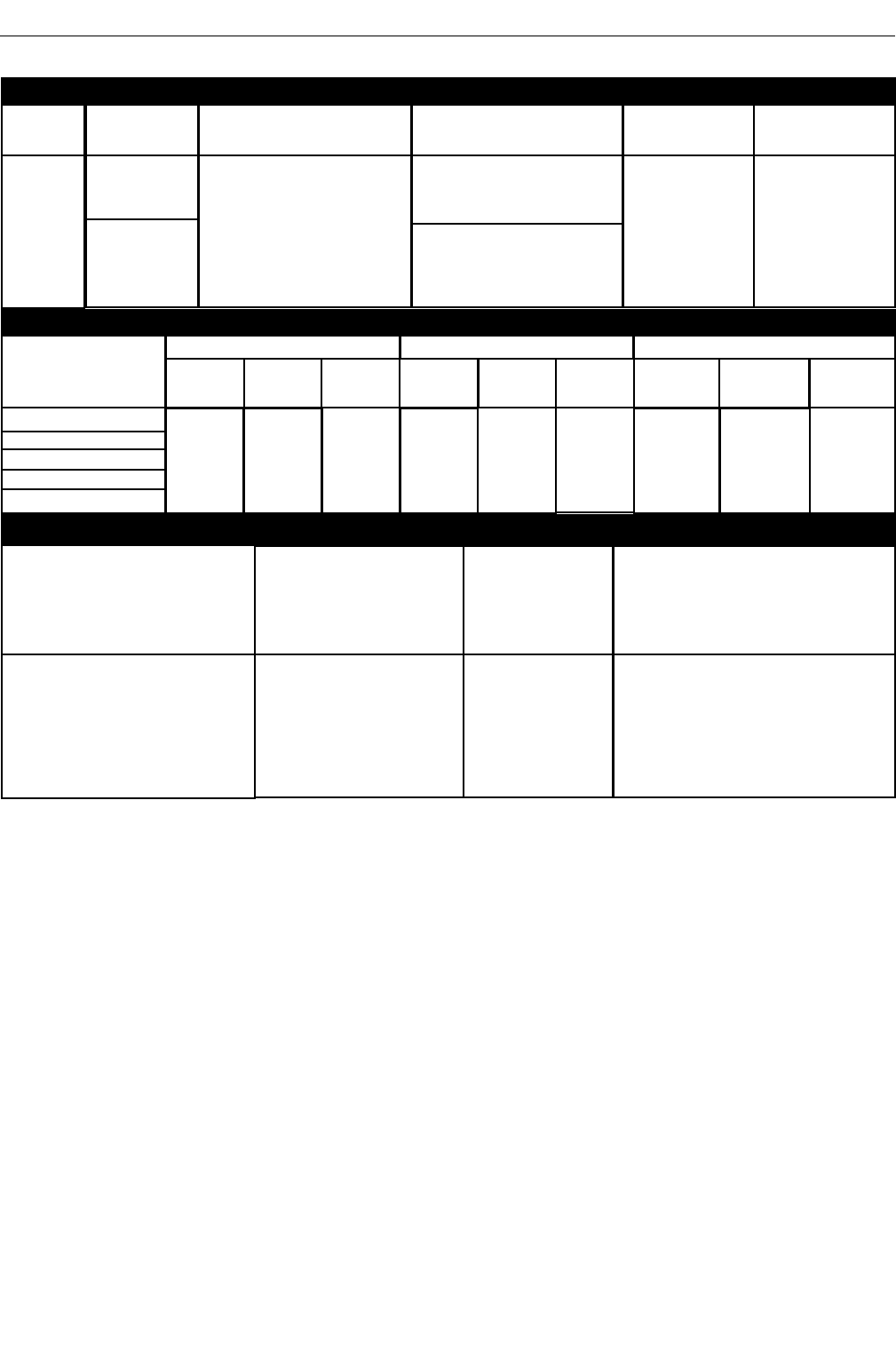
TECHNICAL SPECIFICATIONS - POWER WAVE®R450
RECOMMENDED INPUT WIRE AND FUSE SIZES 1
INPUT
VOLTAGE / PHASE/
FREQUENCY
200-208/3/50/60
230/3/50/60
380-415/3/50/60
460/3/50/60
575/3/50/60
TIME DELAY FUSE
OR BREAKER 2
AMPERAGE
100
90
60
45
35
CORD SIZE 3
AWG SIZES
(mm2)
4 (21)
4 (21)
8 (10)
8 (10)
10 (7)
MAXIMUM INPUT
AMPERE RATING AND
DUTY CYCLE
80A, 40%
73A, 40%
41A, 40%
37A, 40%
29A, 40%
RATED OUTPUT
POWER SOURCE-INPUT VOLTAGE AND CURRENT
Model
K3451-1
K3451-2
Duty Cycle
40% rating
100% rating
450 Amps
36.5 Volts
550 Amps
41.5 Volts
500 Amps
39 Volts
INPUT
VOLTAGE/PHASE/
FREQUENCY
200-208/3/50/60
230/3/50/60
380-415/3/50/60
460/3/50/60
575/3/50/60
Input Amperes
80/73/41/37/29
60/54/31/27/21
Idle Power
500 Watts Max.
(fan on)
Power Factor @
Rated Output
.95
Input Voltage ± 10%
208/230/400*460/575
50/60 Hz
(includes 380V to 415V)
Idle power is less than 50 watts when in Hibernation mode4
1. Based on U.S. National electrical Code
2. Also called " inverse time" or "thermal / magnetic" circuit breakers; circuit breakers that have a delay in tripping action that
decreases as the magnitude of the current increases
3. Type SO cord or similar in 30°C ambient at effective current rating of unit.
4. If supported by the robotic controller software version.
A-1
INSTALLATIONPOWER WAVE®R450
GMAW
40% 60% 100%
GTAW-DC
450 Amps
38 Volts
550 Amps
42 Volts
500 Amps
40 Volts
40% 60% 100%
450 Amps
28 Volts
550 Amps
32 Volts
500 Amps
30 Volts
40% 60% 100%
SMAW
POWER WAVE®R450
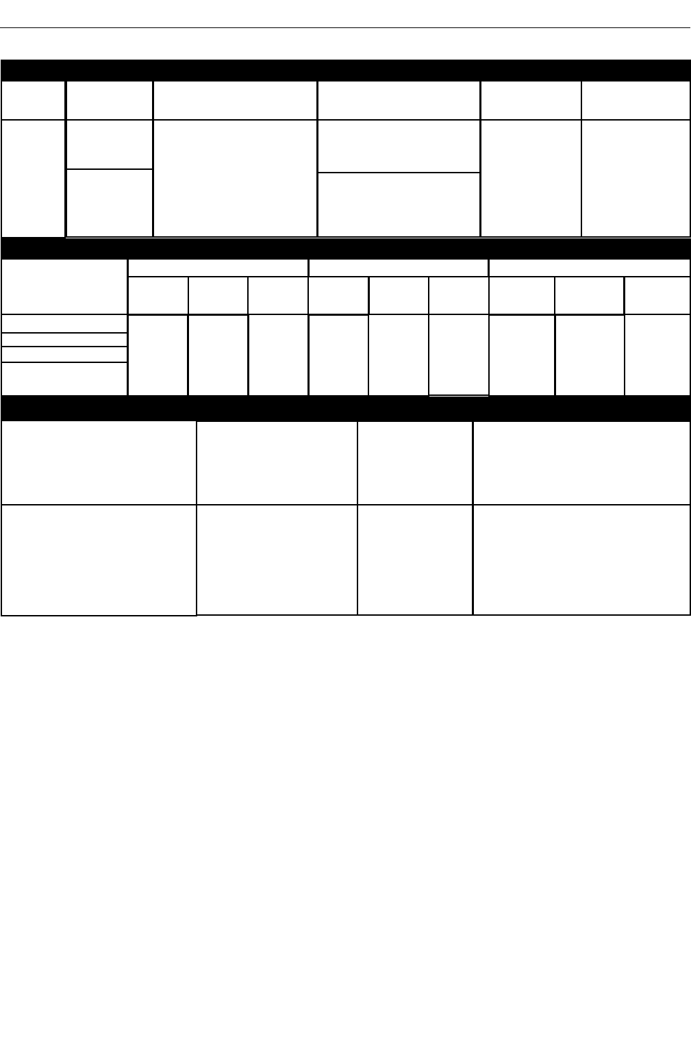
TECHNICAL SPECIFICATIONS - Power Wave®R450 CE
RECOMMENDED INPUT WIRE AND FUSE SIZES 1
INPUT
VOLTAGE / PHASE/
FREQUENCY
230/3/50/60
380-415/3/50/604.
460/3/50/604.
575/3/50/60
TIME DELAY FUSE
OR BREAKER 2
AMPERAGE
90
60
45
35
CORD SIZE 3
AWG SIZES
(mm2)
4 (21)
8 (10)
8 (10)
10 (7)
MAXIMUM INPUT
AMPERE RATING AND
DUTY CYCLE
73A, 40%
41A, 40%
37A, 40%
29A, 40%
RATED OUTPUT
POWER SOURCE-INPUT VOLTAGE AND CURRENT
Model
K3455-1
K3455-2
Duty Cycle
40% rating
100% rating
450 Amps
36.5 Volts
550 Amps
41.5 Volts
500 Amps
39 Volts
INPUT
VOLTAGE/PHASE/
FREQUENCY
230/3/50/60
380-415/3/50/60
460/3/50/60
575/3/50/60*
Input Amperes
73/41/37/29
59/31/27/21
Idle Power
300 Watts Max.
(fan on)
Power Factor @
Rated Output
.95
Input Voltage ± 10%
230/400*460/575
50/60 Hz
(includes 380V to 415V)
Idle power is less than 50 watts when in Hibernation mode5
* For voltages higher than 460V or applications outside the European union replace input cord with properly rated cable.
1. Based on U.S. National electrical Code
2. Also called " inverse time" or "thermal / magnetic" circuit breakers; circuit breakers that have a delay in tripping action that
decreases as the magnitude of the current increases
3. Type SO cord or similar in 30° C ambient at effective current rating of unit.
4. Supplied K3389-1 input cord for these input applications only. For all others consult chart and connect per electrical code.
5. Is supported by the robotic controller software version.
A-2
INSTALLATION
GMAW
40% 60% 100%
GTAW-DC
450 Amps
38 Volts
550 Amps
42 Volts
500 Amps
40 Volts
40% 60% 100%
450 Amps
28 Volts
550 Amps
32 Volts
500 Amps
30 Volts
40% 60% 100%
SMAW
A-3
INSTALLATIONPOWER WAVE®R450
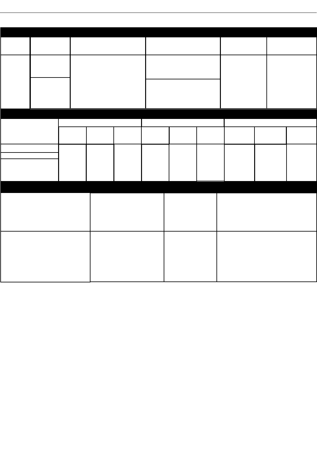
TECHNICAL SPECIFICATIONS - POWER WAVE®R450 CCC
RECOMMENDED INPUT WIRE AND FUSE SIZES 1
INPUT
VOLTAGE / PHASE/
FREQUENCY
380-415/3/50/60
460/3/50/60
575/3/50/60
TIME DELAY FUSE
OR BREAKER 2
AMPERAGE
60
45
35
CORD SIZE 3
AWG SIZES
(mm2)
8 (10)
8 (10)
10 (7)
MAXIMUM INPUT
AMPERE RATING AND
DUTY CYCLE
41A, 40%
37A, 40%
29A, 40%
RATED OUTPUT
POWER SOURCE-INPUT VOLTAGE AND CURRENT
Model
K3456-1
Duty Cycle
40% rating
100% rating
450 Amps
36.5 Volts
550 Amps
41.5 Volts
500 Amps
39 Volts
INPUT
VOLTAGE/PHASE/
FREQUENCY
380-415/3/50/60
460/3/50/60
575/3/50/60
Input Amperes
41/37/29
31/27/21
Idle Power
500 Watts Max.
(fan on)
Power Factor @
Rated Output
.95
Input Voltage ± 10%
400*460/575
50/60 Hz
(includes 380V to 415V)
Idle power is less than 50 watts when in Hibernation mode4
1. Based on U.S. National electrical Code
2. Also called " inverse time" or "thermal / magnetic" circuit breakers; circuit breakers that have a delay in tripping action that
decreases as the magnitude of the current increases
3. Type SO cord or similar in 30°C ambient at effective current rating of unit.
4. If supported by the robotic controller software version.
GMAW
40% 60% 100%
GTAW-DC
450 Amps
38 Volts
550 Amps
42 Volts
500 Amps
40 Volts
40% 60% 100%
450 Amps
28 Volts
550 Amps
32 Volts
500 Amps
30 Volts
40% 60% 100%
SMAW

TEMPERATURE RANGES
HEIGHT
22.45 in ( 570 mm)
MODEL
K3451-1, K3451-2,
K3455-1, K3455-2,
K3456-1
WIDTH
14.00in ( 356 mm)
DEPTH
24.80in ( 630mm)
WEIGHT
150 lbs (68 kg)*
OPERATING TEMPERATURE RANGE
Environmentally Hardened: -4°F to 104°F (-20C to 40C)
STORAGE TEMPERATURE RANGE
Environmentally Hardened: -40°F to 185°F (-40C to 85C)
PROCESS
GMAW
GMAW-Pulse
FCAW
GTAW-DC
SMAW
OUTPUT RANGE (AMPERES)
40-550A
5-550A
OCV (Uo)
Mean Peak
60V 73V
24V 36V
60V 63V
WELDING PROCESS
A-4
INSTALLATIONPOWER WAVE®R450
IP23 155º(F) Insulation Class
*Weight does not include input cord.
PHYSICAL DIMENSIONS
TECHNICAL SPECIFICATIONS - ALL MODELS
INSTALLATION
SAFETY PRECAUTIONS
Read this entire installation section before you start installation.
ELECTRIC SHOCK can kill.
• Only qualified personnel should perform
this installation.
• Turn the input power OFF at the
disconnect switch or fuse box before
working on this equipment. Turn off the input power to
any other equipment connected to the welding system
at the disconnect switch or fuse box before working on
the equipment.
• Do not touch electrically hot parts.
• Always connect the POWER WAVE
®
R450 grounding
lug to a proper safety (Earth) ground.
sELECt suItaBLE LOCatIOn
The POWER WAVE®R450 will operate in harsh environments.
Even so, it is important that simple preventative measures are
followed in order to assure long life and reliable operation.
• The machine must be located where there is free circulation
of clean air such that air movement in the back, out the sides
and bottom will not be restricted.
• Dirt and dust that can be drawn into the machine should be
kept to a minimum. The use of air filters on the air intake is
not recommended because normal air flow may be restricted.
Failure to observe these precautions can result in excessive
operating temperatures and nuisance shutdown.
• Keep machine dry. Shelter from rain and snow. Do not place
on wet ground or in puddles.
• Do not mount the POWER WAVE®R450 over combustible
surfaces. Where there is a combustible surface directly under
stationary or fixed electrical equipment, that surface shall be
covered with a steel plate at least .060” (1.6mm) thick, which
shall extend not less than 5.90” (150mm) beyond the
equipment on all sides.
LIFtIng
Both handles should be used when lifting POWER WAVE®R450.
When using a crane or overhead device a lifting strap should be
connected to both handles. Do not attempt to lift the
POWER WAVE®R450 with accessories attached to it.
staCkIng
The POWER WAVE®R450 cannot be stacked.
tILtIng
Place the machine directly on a secure, level surface or on a
recommended undercarriage. The machine may topple over if this
procedure is not followed.
InPut and grOund COnnECtIOns
Only a qualified electrician should connect the POWER WAVE®
R450. Installation should be made in accordance with the
appropriate National Electrical Code, all local codes and the
information in this manual.
FALLING EQUIPMENT
can cause injury.
• Lift only with equipment of adequate
lifting capacity.
• Be sure machine is stable when lifting.
• Do not operate machine while suspended when lifting.
MaChInE grOundIng
The frame of the welder must be grounded. A ground terminal
marked with a ground symbol is located next to the input power
connection block.
See your local and national electrical codes for proper grounding
methods.
hIgh FrEQuEnCy PrOtECtIOn
Locate the POWER WAVE®R450 away from radio controlled
machinery. The normal operation of the POWER WAVE®R450
may adversely affect the operation of RF controlled equipment,
which may result in bodily injury or damage to the equipment.
FCC rEguLatOry statEMEnt
This equipment has been tested and found to comply with the
limits for a Class B digital device. For FCC ID number see the
complete regulatory statement at the beginning of this manual.
WARNING
WARNING
A-5
INSTALLATIONPOWER WAVE®R450
Only a qualified electrician should connect
the input leads to the POWER WAVE®R450.
Connections should be made in accor-
dance with all local and national electrical
codes and the connection diagrams. Failure to do so
may result in bodily injury or death.
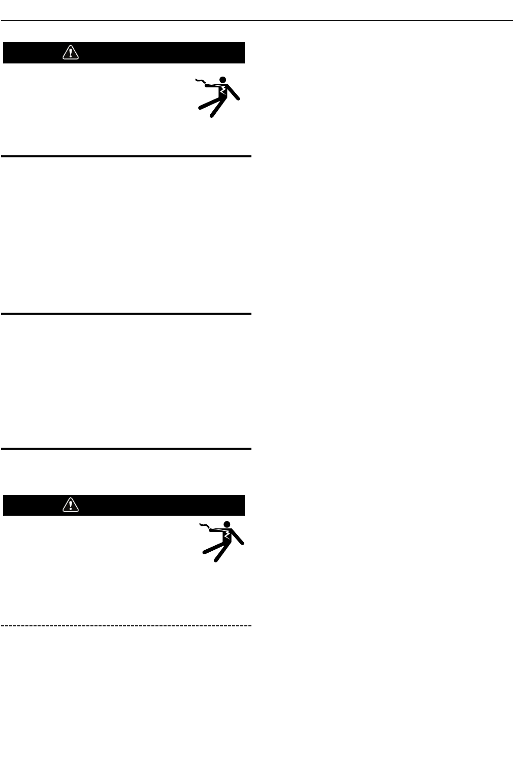
InPut COnnECtIOn
(See Figure A.1)
Use a three-phrase supply line. A 1.40 inch diameter access hole
with strain relief is located on the case back. Route input power
cable through this hole and connect L1, L2, L3 and ground per
connection diagrams and National Electric Code. To access the
input power connection block, remove three screws holding the
access door to the side of the machine.
ALWAYS CONNECT THE POWER WAVE GROUNDING LUG (LOCATED
AS SHOWN IN FIGURE A.1) TO A PROPER SAFETY (EARTH)
GROUND.
InPut FusE and suPPLy WIrE COnsIdEratIOns
Refer to Specification Section for recommended fuse, wire sizes
and type of the copper wires. Fuse the input circuit with the
recommended super lag fuse or delay type breakers (also called
"inverse time" or "thermal/magnetic" circuit breakers). Choose
input and grounding wire size according to local or national
electrical codes. Using input wire sizes, fuses or circuit breakers
smaller than recommended may result in "nuisance" shut-offs
from welder inrush currents, even if the machine is not being used
at high currents.
InPut VOLtagE sELECtIOn
The POWER WAVE®R450 automatically adjusts to work with
different input voltages. No reconnect switch settings are required.
The POWER WAVE®R450 ON/OFF switch is
not intended as a service disconnect for this
equipment. Only a qualified electrician
should connect the input leads to the
POWER WAVE®R450. Connections should be made in
accordance with all local and national electrical codes
and the connection diagram located on the inside of the
reconnect access door of the machine. Failure to do so
may result in bodily injury or death.
WARNING
WARNING
A-6
INSTALLATIONPOWER WAVE®R450
On some models, toroids are on the power cord. When replacing
the power cord, it is important to put the toroids on the new power
cord in the same location and with the same number of turns.
A-7
INSTALLATIONPOWER WAVE®R450
POWER CONNECTION BLOCK
INPUT CORD STRAIN RELIEF
CONNECT EACH PHASE OF A THREE-PHASE
CONDUCTOR HERE
GROUND CONNECTION
CONNECT GROUND LEAD PER LOCAL
AND NATIONAL ELECTRIC CODE
ROUTE INPUT CORD
THROUGH RELIEF AND
TWIST NUT TO TIGHTEN
INPUT POWER
ACCESS DOOR
FIGURE A.1 for K3451-1, K3451-2, K3456-1
CONNECT EACH PHASE OF A
THREE-PHASE CONDUCTOR
HERE
INPUT POWER
ACCESS DOOR
INPUT CORD
STRAIN RELIEF
CE FILTER
GROUND CONNECTION
CONNECT GROUND
LEAD PER LOCAL AND
NATIONAL ELECTRIC CODE
ROUTE INPUT CORD THROUGH
RELIEF AND TWIST NUT TO TIGHTEN
FIGURE A.1 - for K3455-1 & K3455-2
A-8
INSTALLATIONPOWER WAVE®R450
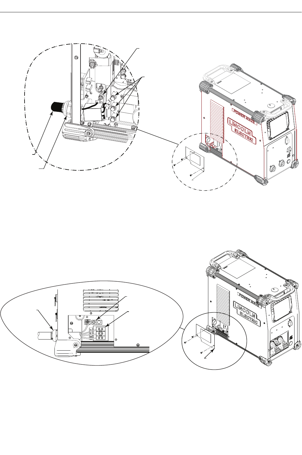
GMAW (MIG) WELDING
An ArcLink compatible wire feeder is recommended for Mig weld-
ing. Refer to Figure A.3 for the connection details.
FIGURE A.3
Avoid excessive lengths and
do not coil excess cable
Ethernet
Control
Cable
Remote Sense Lead
Work Cable
Work Piece
Electrode Cable
Water
Feeder
Dress Out
Kit
Flowmeter
Torch
rECOMMEndEd WOrk CaBLE sIZEs FOr arC
WELdIng
Connect the electrode and work cables between the appropriate
output studs of the POWER WAVE®R450 per the following
guidelines:
• Most welding applications run with the electrode being
positive (+). For those applications, connect the electrode
cable between the wire drive feed plate and the positive (+)
output stud on the power source. Connect a work lead from
the negative (-) power source output stud to the work piece
• When negative electrode polarity is required, such as in some
Innershield applications, reverse the output connections at
the power source (electrode cable to the negative (-) stud,
and work cable to the positive (+) stud).
Negative electrode polarity operation WITHOUT use of a
remote work sense lead (21) requires the Negative
Electrode Polarity attribute to be set. See the Remote
Sense Lead Specification section of this document for
further details.
For additional Safety information regarding the electrode and work
cable set-up, See the standard “SAFETY INFORMATION” located in
the front of this Instruction Manual.
gEnEraL guIdELInEs
•
Select the appropriate size cables per the “Output Cable
Guidelines” below.
Excessive voltage drops caused by
undersized welding cables and poor connections often result
in unsatisfactory welding performance. Always use the
largest welding cables (electrode and work) that are practical,
and be sure all connections are clean and tight.
Note: Excessive heat in the weld circuit indicates undersized
cables and/or bad connections.
• Route all cables directly to the work and wire feeder, avoid
excessive lengths and do not coil excess cable.
Route the
electrode and work cables in close proximity to one another
to minimize the loop area and therefore the inductance of the
weld circuit.
• Always weld in a direction away from the work (ground)
connection.
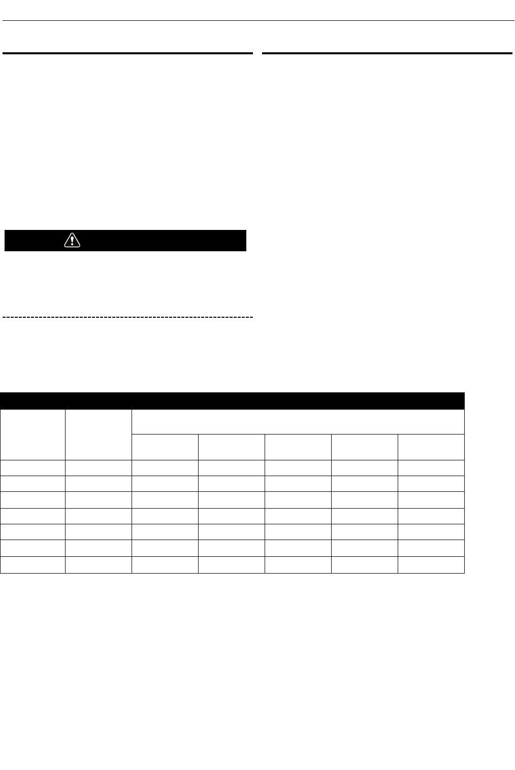
Table A.1 shows copper cable sizes recommended for different
currents and duty cycles. Lengths stipulated are the distance from
the welder to work and back to the welder again. Cable sizes are
increased for greater lengths primarily for the purpose of
minimizing cable drop.
CAUTION
A-9
INSTALLATIONPOWER WAVE®R450
** Tabled values are for operation at ambient temperatures of 104°F (40°C) and below. Applications above 104°F (40°C) may require cables larger
than recommended, or cables rated higher than 167°F (75°C).
TABLE A.1 - RECOMMENDED CABLE SIZES - RUBBER COVERED COPPER - RATED 167°F (75°C)**
AMPERES PERCENT DUTY
CYCLE
CABLE SIZES FOR COMBINED LENGTHS OF ELECTRODE AND WORK CABLES
0 TO 50 FT. 50 TO 100 FT. 100 TO 150 FT. 150 TO 200 FT. 200 TO 250 FT.
200 100 2 2 2 1 1/0
250 100 1 1 1 1 1/0
300 100 2/0 2/0 2/0 2/0 3/0
400 100 3/0 3/0 3/0 3/0 4/0
450 100 3/0 3/0 4/0 4/0 2-3/0
500 60 2/0 2/0 3/0 3/0 4/0
550 40 2/0 2/0 3/0 3/0 4/0
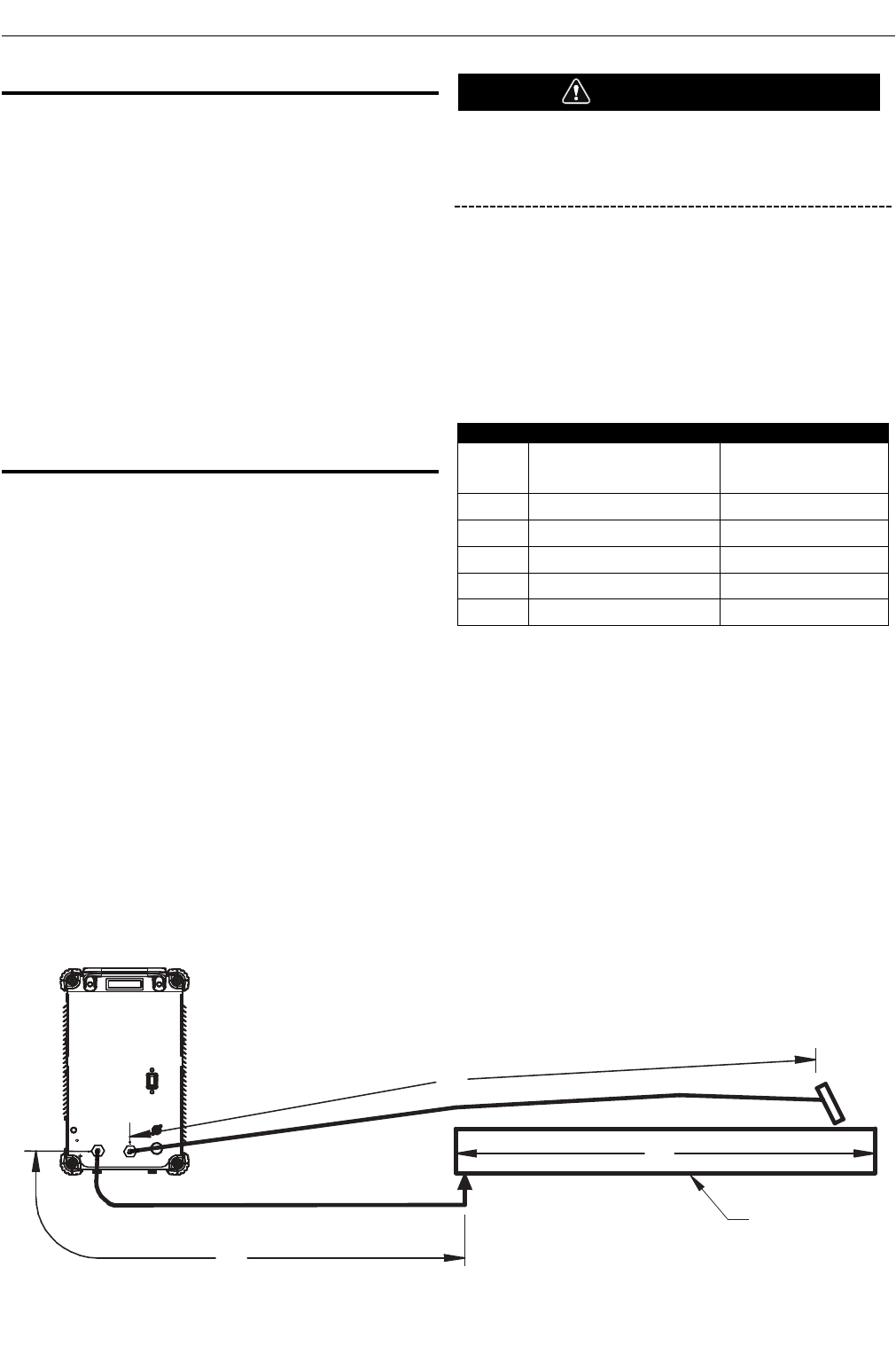
CaBLE InduCtanCE and Its EFFECts On
WELdIng
Excessive cable inductance will cause the welding performance to
degrade. There are several factors that contribute to the overall
inductance of the cabling system including cable size, and loop
area. The loop area is defined by the separation distance between
the electrode and work cables, and the overall welding loop
length. The welding loop length is defined as the total of length of
the electrode cable (A) + work cable (B) + work path (C) (See
Figure A.5).
To minimize inductance always use the appropriate size cables,
and whenever possible, run the electrode and work cables in close
proximity to one another to minimize the loop area. Since the most
significant factor in cable inductance is the welding loop length,
avoid excessive lengths and do not coil excess cable. For long
work piece lengths, a sliding ground should be considered to keep
the total welding loop length as short as possible.
rEMOtE sEnsE LEad sPECIFICatIOns
Voltage Sensing Overview
The best arc performance occurs when the POWER WAVE®R450
has accurate data about the arc conditions.
Depending upon the process, inductance within the electrode and
work cables can influence the voltage apparent at the studs of the
welder, and have a dramatic effect on performance. Remote
voltage sense leads are used to improve the accuracy of the arc
voltage information supplied to the control pc board. Sense Lead
Kits (K940-xx) are available for this purpose.
The POWER WAVE®R450 has the ability to automatically sense
when remote sense leads are connected. With this feature there
are no requirements for setting-up the machine to use remote
sense leads. This feature can be disabled through the Weld
Manager Utility (available at www.powerwavesoftware.com) or
through the set up menu (if a user interface is installed into the
power source).
If the auto sense lead feature is disabled and remote
voltage sensing is enabled but the sense leads are
missing or improperly connected extremely high welding
outputs may occur.
General Guidelines for Voltage Sense Leads
Sense leads should be attached as close to the weld as practical,
and out of the weld current path when possible. In extremely
sensitive applications it may be necessary to route cables that
contain the sense leads away from the electrode and work
welding cables.
Voltage sense leads requirements are based on the weld process
(See Table A.2)
(1) The electrode voltage sense lead (67) is automatically enabled by the weld
process, and integral to the 5 pin ArcLink control cable (K1543-xx).
(2) When a work voltage sense lead (21) is connected the power source will auto-
matically switch over to using this feedback (if the auto sense feature is
enable).
(3) Negative polarity semi-automatic process operation WITHOUT use of a remote
work sense lead (21) requires the Negative Electrode Polarity attribute to be set.
(4) STT requires an STT or Advanced Module.
CAUTION
TABLE A.2
Process Electrode Voltage Sensing (1)
67 lead
Work Voltage Sensing (2)
21 lead
GMAW 67 lead required 21 lead optional
(3)
GMAW-P 67 lead required 21 lead optional
(3)
STT467 lead required 21 lead required
FCAW 67 lead required 21 lead optional
(3)
GTAW Voltage sense at studs Voltage sense at studs
FIGURE A.5
B
A
C
WORK
POWER
WAVE
R450
A-10
INSTALLATIONPOWER WAVE®R450

Electrode Voltage Sensing
The remote ELECTRODE sense lead (67) is built into the ArcLink
control cable and is always connected to the wire drive feed plate
when a wire feeder is present. Enabling or disabling electrode
voltage sensing is application specific, and automatically
configured by the active weld mode.
If the auto sense lead feature is disabled and the weld
polarity attribute is improperly configured extremely high
welding outputs may occur.
Work Voltage Sensing
While most applications perform adequately by sensing the work
voltage directly at the output stud, the use of a remote work
voltage sense lead is recommended for optimal performance. The
remote WORK sense lead (21) can be accessed through the four-
pin voltage sense connector located on the control panel by using
the K940 Sense Lead Kit. It must be attached to the work as close
to the weld as practical, but out of the weld current path. For more
information regarding the placement of remote work voltage
sense leads, see in this section entitled "Voltage Sensing
Considerations for Multiple Arc Systems."
Negative Electrode Polarity
The POWER WAVE®R450 has the ability to automatically sense
the polarity of the sense leads. With this feature there are no set-
up requirements for welding with negative electrode polarity. This
feature can be disabled through the Weld Manager Utility
(available at www.powerwavesoftware.com) or through the set up
menu (if a user interface is installed into the power source).
CAUTION
A-11
INSTALLATIONPOWER WAVE®R450
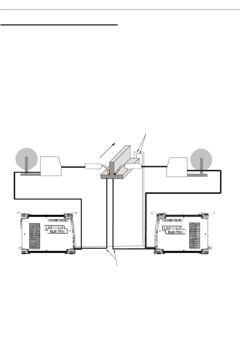
VOLtagE sEnsIng COnsIdEratIOns FOr
MuLtIPLE arC systEMs
Special care must be taken when more than one arc is welding
simultaneously on a single part. Multiple arc applications do not
necessarily dictate the use of remote work voltage sense leads,
but they are strongly recommended.
If Sense Leads ARE NOT Used:
• Avoid common current paths. Current from adjacent arcs can
induce voltage into each others current paths that can be
misinterpreted by the power sources, and result in arc inter-
ference.
If Sense Leads ARE Used:
• Position the sense leads out of the path of the weld current.
Especially any current paths common to adjacent arcs. Current
from adjacent arcs can induce voltage into each others current
paths that can be misinterpreted by the power sources, and
result in arc interference.
• For longitudinal applications, connect all work leads at one end
of the weldment, and all of the work voltage sense leads at the
opposite end of the weldment. Perform welding in the direction
away from the work leads and toward the sense leads.
(See Figure A.6)
DIRECTION
OF TRAVEL
CONNECT ALL
WORK LEADS AT
THE BEGINNING
OF THE WELD.
CONNECT ALL SENSE
LEADS AT THE END
OF THE WELD.
FIGURE A.6
A-12
INSTALLATIONPOWER WAVE®R450