The Nielsen 001 CONSUMER SHOPPING MONITORING SYSTEM User Manual REVISIONS
The Nielsen Co. CONSUMER SHOPPING MONITORING SYSTEM REVISIONS
Users Manual
REVISIONS
LTR DESCRIPTION DATE APPROVED
1 ECO 006600 TJV
This document is set up for two-sided copying. Printing single-sided produces blank pages.
REVISION 1
SHEET All
AUTHENTICATION Installation Instructions
PREPARED BY DATE for In-Store Tracking
Fred Martensen
Rafael Alonso
Lore Eargle
08/07/2008 SHEET
1 of 24
NMR#
403-2338-018
Copyright © 2008. The Nielsen Company. All rights reserved.
This page intentionally left blank.

Installation Guide for In-Store Tracking
Contents
1. Introduction ........................................................................................................................................... 1
1.1. Purpose ..................................................................................................................................... 1
1.2. Background................................................................................................................................ 2
1.3. Description................................................................................................................................. 3
2. Related Documents .............................................................................................................................. 4
3. Operational Specifications .................................................................................................................... 5
3.1. Shelf Transmitter Module .......................................................................................................... 5
3.2. Shelf Receiver Module .............................................................................................................. 5
3.3. Cart Module ............................................................................................................................... 6
3.4. Checkout/Repeater Module.......................................................................................................6
4. Required Parts and Tools ..................................................................................................................... 7
Tools Required for Installation................................................................................................... 7
5. FCC....................................................................................................................................................... 8
6. Installation Procedures ......................................................................................................................... 9
6.1. Installing the Shelf Transmitter Module: .................................................................................... 9
6.2. Installing the Shelf Receiver Module with Battery/Communications Pack ..............................12
6.3. Installing the Cart Module........................................................................................................ 14
6.4. Installing the Checkout/Repeater Module ............................................................................... 16
7. Verification Test .................................................................................................................................. 17
7.1. Required Parts......................................................................................................................... 17
7.2. Test Procedure ........................................................................................................................ 17
8. Troubleshooting .................................................................................................................................. 18
403-2338-018 i

Installation Guide for In-Store Tracking
List of Figures
Figure 1. Module Interactions ....................................................................................................................... 2
Figure 2. Zone Layout 1 ................................................................................................................................ 3
Figure 3. Shelf Transmitter and its Battery Unit............................................................................................ 5
Figure 4. Shelf Receiver and its Battery/COM Unit ...................................................................................... 5
Figure 5. Cart Module ................................................................................................................................... 6
Figure 6. Checkout/Repeater Module ........................................................................................................... 6
Figure 7. Positions as Viewed from the End ................................................................................................. 9
Figure 8. Shelf Transmitter with Screws Removed....................................................................................... 9
Figure 10. Installed Shelf Transmitter ......................................................................................................... 11
Figure 11. Installed Shelf Transmitter and Battery Unit .............................................................................. 11
Figure 12. Installed Shelf Receiver ............................................................................................................. 12
Figure 13. Installed Shelf Receiver ............................................................................................................. 12
Figure 14. Installed Battery Pack/COM Unit ............................................................................................... 13
Figure 15. Back plate mounted on shopping cart ....................................................................................... 14
Figure 16. Correct placement of Cart Module between thick cart rails ....................................................... 15
Figure 17. Wrong placement of Cart Module straddling thick cart rails ...................................................... 15
Figure 18. Checkout/Repeater Module Attached with Zip Ties .................................................................. 16
Figure 19. Checkout/Repeater Module--Wall Mount .................................................................................. 16
Figure 20. Battery Unit for Shelf Transmitter .............................................................................................. 18
List of Tables
Table 1. Parts Required for Installation......................................................................................................... 7
ii 403-2338-018

Installation Guide for In-Store Tracking
1. Introduction
Nielsen In-Store is a global measurement service designed to help marketing
professionals better understand how to reach and influence consumers in retail
environments. Nielsen In-Store measures consumer exposure to in-store marketing
vehicles, including television, radio, shelf talkers, digital signage, and other point-of-
purchase displays.
1.1. Purpose
This document provides installation instructions on installing four modules in the In-
Store Tracking system:
• Shelf Transmitter Module and Battery Pack
• Shelf Receiver Module and Battery Pack/COM Module
• Cart Module
• Checkout/Repeater Module
It does not cover installation of the In-Store Unit (ISU).
403-2338-018 1
Installation Guide for In-Store Tracking
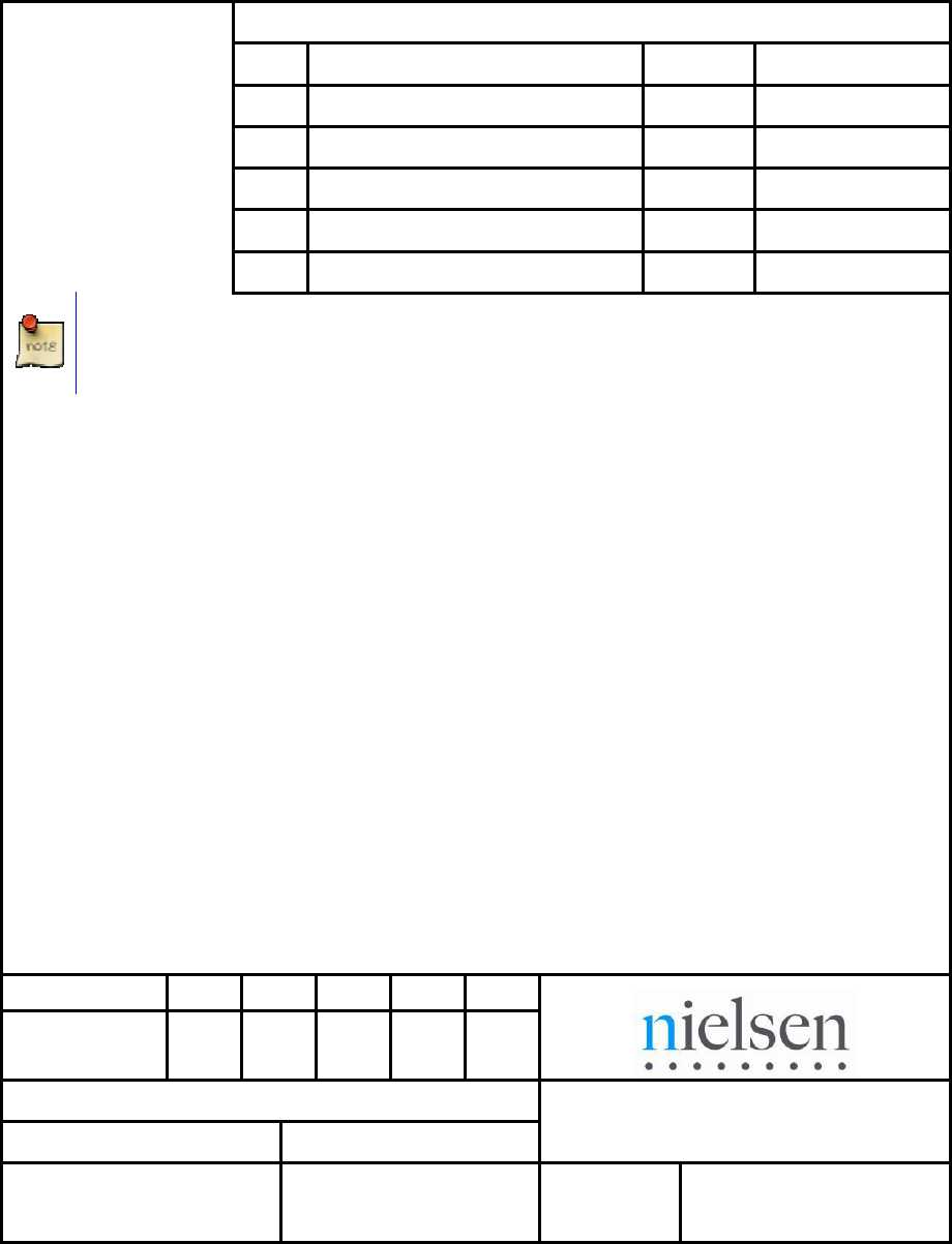
1.2. Background
The In-Store Tracking system consists of several devices that transmit and receive
signals throughout a store and send counting information to a PC known as the In-
Store Unit (ISU). Each module that is battery-operated has a built-in alert system
which informs the ISU when the battery is approaching the end of its charge.
Figure 1. Module Interactions
See the diagram provided with the installation kit for specifics on setting up a
specific store.
2 403-2338-018

Installation Guide for In-Store Tracking
1.3. Description
In-Store Operations divides a store floor plan is into zones of interest, typically aisles
and end caps. They designate the placement of the equipment throughout the store.
The marked-up floor plan shows the location for each Shelf Transmitter, as
designated by its unique ID, and assigns the transmitters throughout the store to
achieve the desired granularity. The carts are fitted with Cart Modules. As a Cart
Module passes a Shelf Transmitter, the Cart Module timestamps and captures the
unique ID of the Shelf Transmitter.
Acting solely as a bridge, the Checkout/Repeater Module relays the data to a 900
MHz RF modem that links to the In-Store Unit (ISU), a Linux-based PC located in the
office of the retail store. The ISU transmits the captured data from the store and
sends this data to the Back Office. [Note: In Europe and other locations, the
Checkout/Repeater Module transmits at 2.4 GHz.]
Figure 2. Zone Layout 1
403-2338-018 3

Installation Guide for In-Store Tracking
2. Related Documents
• In-Store Tracking Device Diagram
• System Diagram
4 403-2338-018
Installation Guide for In-Store Tracking
3. Operational Specifications
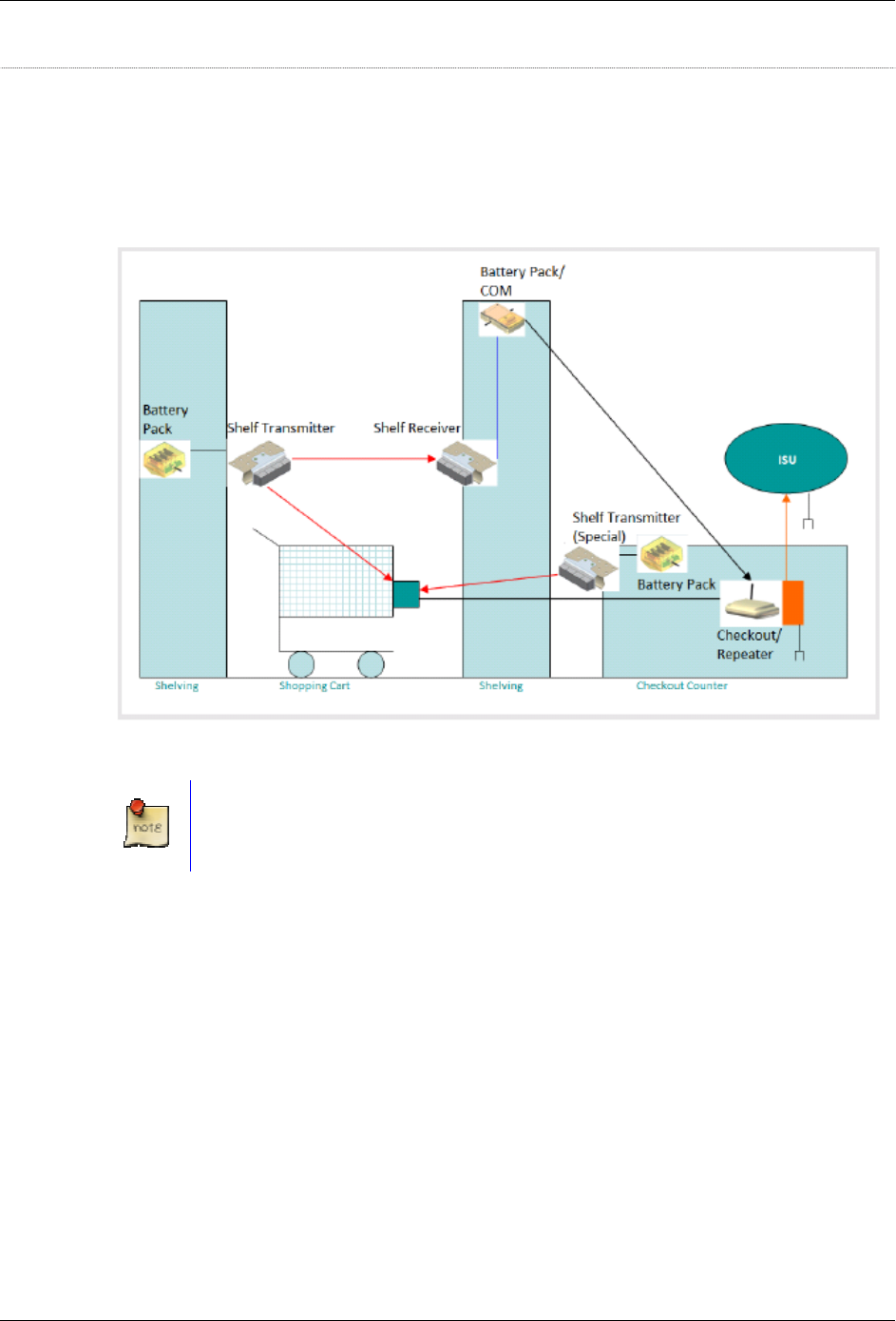
3.1. Shelf Transmitter Module
Shelf Transmitter (Tx) Module—located on shelves throughout a retail store. Each
has a separate Battery Unit and transmits two infrared (IR) beams, a tracking and a
counting beam.
Figure 3. Shelf Transmitter and its Battery Unit
• The counting beam points across to the Shelf Receiver Module mounted on the
self edge on the same aisle opposite the Shelf Transmitter Module.
• The tracking beam has a unique ID that identifies its location within the store. It
points downward so that a Cart Module can detect the beam as the cart passes
it.
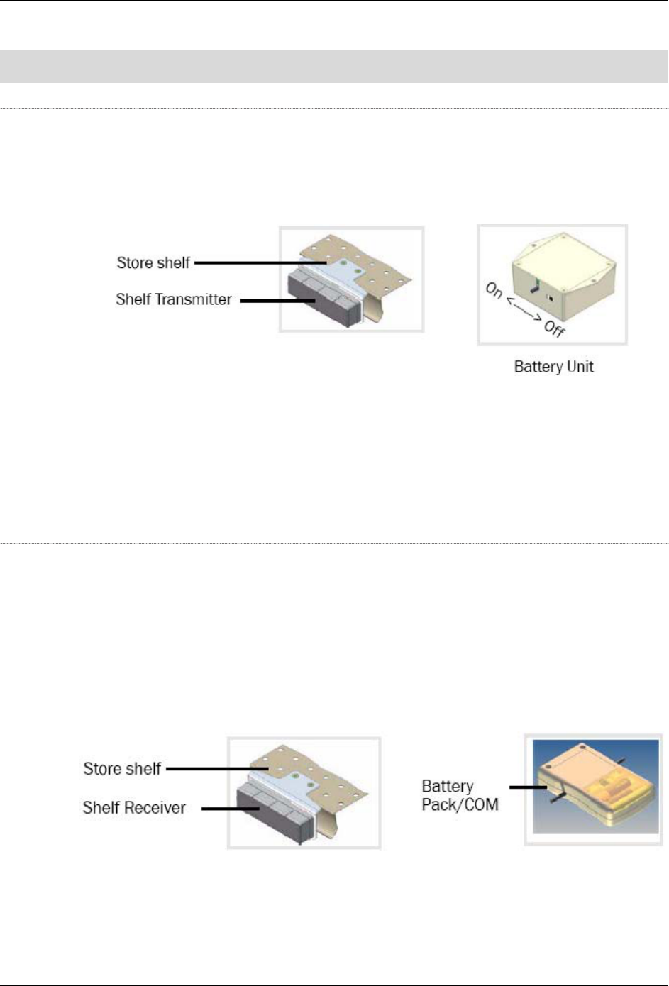
3.2. Shelf Receiver Module
Shelf Receiver (Rx) Module—located on a store shelf opposite a Shelf Transmitter
Module, it looks just like the transmitter except that it has a flat Battery-Pack/COM
Module attached to it. The Receiver has two IR sensors that receive transmissions
from the Shelf Transmitter across the aisle. The receiver counts traffic and detects
the direction of travel. It uses an RF transmitter (802.15.4) to report traffic to the
Checkout/Repeater Module. When its sensors are triggered, its MCU receives an
interrupt, and it checks the status of its two IR sensors.
Figure 4. Shelf Receiver and its Battery/COM Unit
• If both sensors are triggered, no one is crossing.
403-2338-018 5
Installation Guide for In-Store Tracking
• If one sensor is on and the other is off, one trip is captured. It records the
direction and timestamp stored in the buffer.
• When its buffer is full or after a preset interval, whichever occurs first, the Shelf
Receiver and Battery Pack/COM Module sends the received data to the ISU.
3.3. Cart Module
The Cart Module is mounted on shopping carts. This module receives and stores the
IR IDs transmitted from the Shelf Transmitter Modules. It uses an RF transmitter
(802.15.4) to report traffic to the Checkout/Repeater Module. When its buffer is full or
at a preset interval, it sends the data to the ISU through the Checkout/Repeater
Module. The Cart Module consists of the following:
• IR receiver
• Micro controller
• Radio frequency transmitter
Figure 5. Cart Module
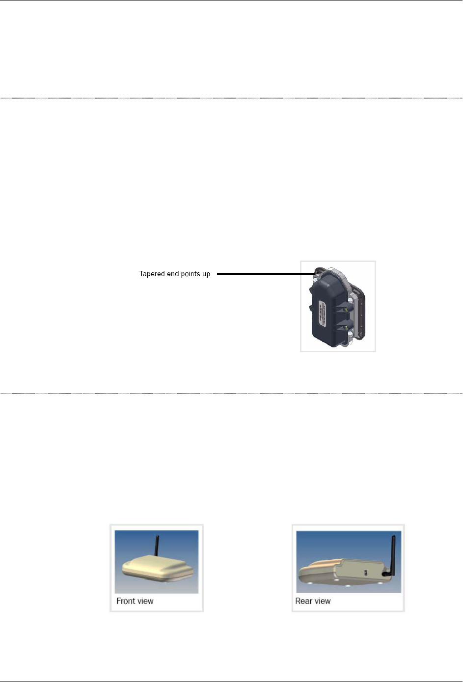
3.4. Checkout/Repeater Module
The Checkout/Repeater Module is located throughout the store. It is wall-powered. It
uses RF (802.15.4) to receive data from the Shelf Receiver and Cart Modules. Using
an attached (off-the-shelf) 900 MHz RF transmitter module, it forwards data to the
ISU. [In Europe and other locations, it transmits at 2.4 GHz.] The Checkout/Repeater
simply receives data from either the Shelf Receiver Module or the Cart Module via
RF (802.15.4) and forwards the data to the ISU via the 900 Mhz (or 2.4 GHz) RF
transmitter module.
Figure 6. Checkout/Repeater Module
6 403-2338-018
Installation Guide for In-Store Tracking
4. Required Parts and Tools
Table 1. Parts Required for Installation
Item Part #
Alcohol wipes 006-1251-000
Cart Module 501-2227-000
Fastener, 3M™ Dual Lock™ reclosable 269-0083-000
Module, Checkout/Repeater 501-1508-000
Module, Shelf Receiver (Rx) with Battery
Pack/Communications (COM) Unit
501-1509-000
Module, Shelf Transmitter (Tx) 501-1510-000
Nut, hex with cap 272-0031-000
Screws, #8 =32x1/2” 062-0310-000
Screws, #8-32x3/4” 062-0317-000
Screw, #8x1” 062-0316-000
Tape, double-stick 269-0072-000
Tie wrap, 4”, thick 267-0017-001
Tie wrap, 4”, thin 267-0001-001
Tie wrap anchor, 1” pressure-sensitive
adhesive
267-0015-000
Tools Required for Installation
• Ladder, 6-foot
• Ladder, 12-foot
• Pliers
• Scissors
• Screwdriver, #1 Phillips
• Screwdriver, #2 Phillips
• Utility cart
• Wire cutters
403-2338-018 7

Installation Guide for In-Store Tracking
5. FCC
FCC0003729381WHR001
This device complies with Part 15 of the FCC Rules. Operation is subject to the
following two conditions: (1) this device may not cause harmful interference, and (2)
this device must accept any interference received, including interference that may
cause undesired operation.
Modular Approval: The antenna(s) used for this transmitter must be installed to
provide a separation distance of at least 20 cm from all persons and must not be co-
located or operating in conjunction with any other antenna or transmitter. End-users
and installers must be provided with antenna installation and transmitter operating
conditions for satisfying RF exposure compliance.
Changes or modifications not expressly approved by the party responsible for
compliance could void the user's authority to operate the equipment.
8 403-2338-018
Installation Guide for In-Store Tracking
6. Installation Procedures
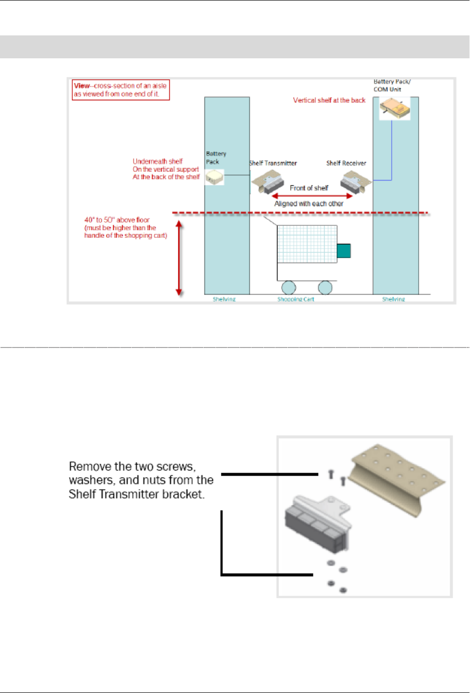
Figure 7. Positions as Viewed from the End
6.1. Installing the Shelf Transmitter Module:
1. The module arrives with the power off. To turn the unit on, while looking at the
unit from the top, slide the switch toward the cable.
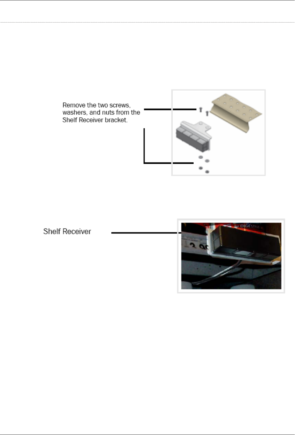
2. Do the following:
Figure 8. Shelf Transmitter with Screws Removed
403-2338-018 9
Installation Guide for In-Store Tracking
3. Using the screws, washers, and nuts, attach the unit to a shelf in a position with
these characteristics:
o With the black, plastic housing facing toward the aisle.
o 40” to 50” above the floor, which should be barely higher (and never lower)
than the handle of a store shopping cart.
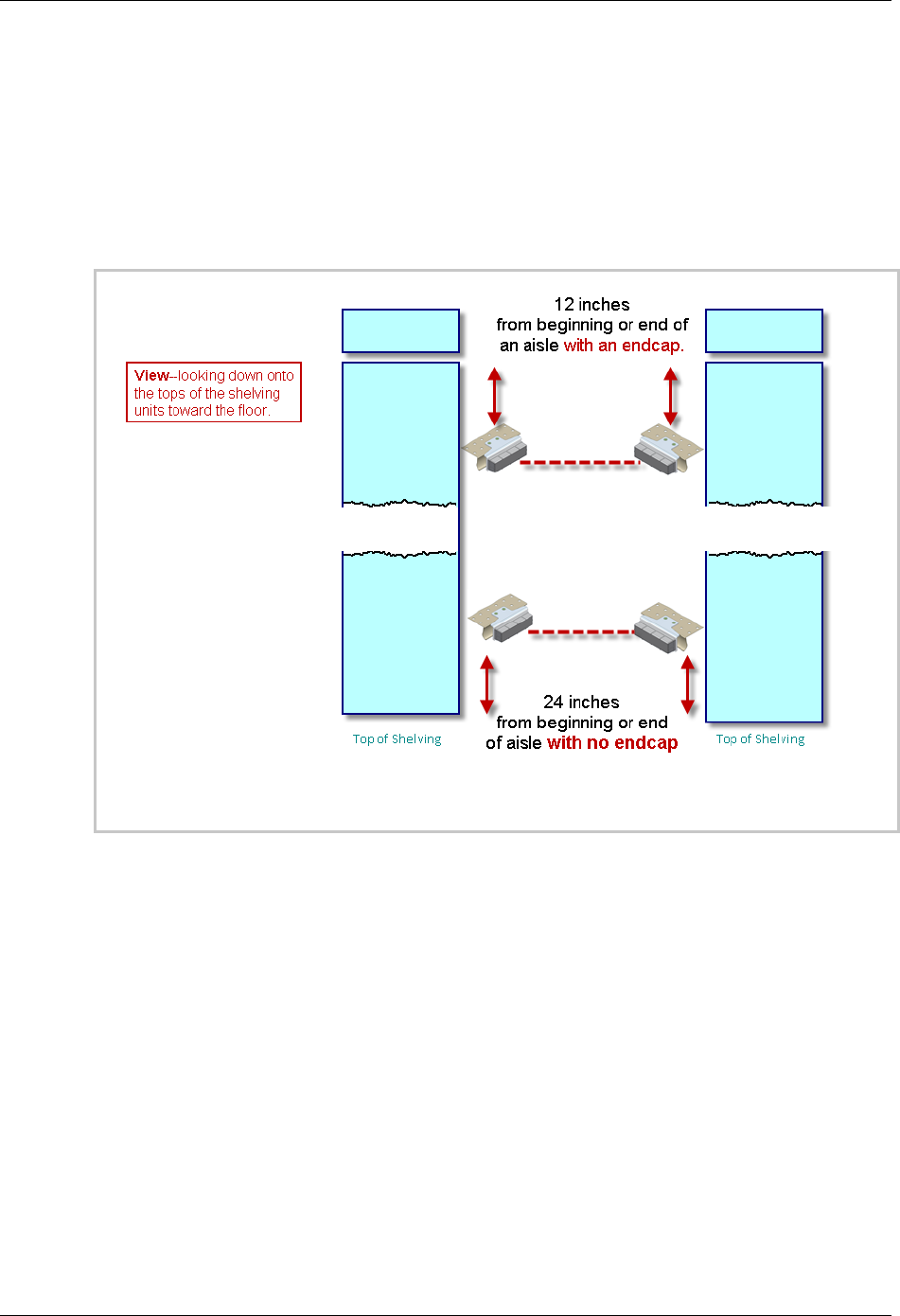
o For shelving with an endcap—a minimum of 12 inches from the shelf end.
o For shelving with no endcap—a minimum of 24 inches from the shelf end.
Figure 9. Positions as Viewed from Above
o Away from any shelf space that would be used for store products and yet with
a clear line of sight to the position where you will place the receiver.
o If either the Transmitter or the Receiver has to be placed higher, select the
Transmitter as the higher one.
o If the assigned location does not let you properly align the two modules
because of shelf design or product layout, adjust the horizontal placement of
the Transmitter and Receiver as necessary within the aisle.
10 403-2338-018
Installation Guide for In-Store Tracking
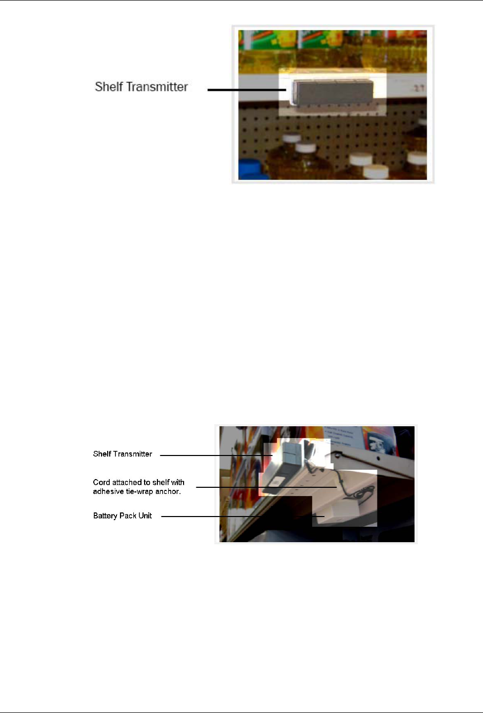
Figure 10. Installed Shelf Transmitter
4. Route the cord between the transmitter and the battery pack unit so that it is
hidden beneath the shelves and behind the supports.
5. Plug into header P1.
6. Using alcohol wipes, clean the areas where you will place the tie wrap anchors
and reclosable fasteners.
7. So the cord cannot easily be disturbed or removed, attach it to the shelving with
pressure-sensitive adhesive tie wrap anchors.
8. Attach the battery unit to the shelving with reclosable fasteners in the following
way:
o On the upright for the shelf.
o Away from store products.
o With the switch accessible.
Figure 11. Installed Shelf Transmitter and Battery Unit
403-2338-018 11
Installation Guide for In-Store Tracking
6.2. Installing the Shelf Receiver Module with
Battery/Communications Pack
1. The module arrives with the power off. To turn the unit on, while looking at the
unit from the top, slide the switch toward the cable.
2. Do the following:
Figure 12. Installed Shelf Receiver
3. Using the screws, washers, and nuts, attach the receiver unit so the black plastic
housing is in line with the transmitter unit across the aisle.
Figure 13. Installed Shelf Receiver
o With the black, plastic housing facing toward the aisle.
o 40” to 50” above the floor, which should be barely higher (and never lower)
than the handle of a store shopping cart.
o Away from any shelf space that would be used for store products and yet with
a clear line of sight to the position where you placed the Transmitter.
o If either the Transmitter or the Receiver has to be higher than the other,
select the Transmitter as the higher one.
4. Using alcohol wipes, clean the areas where you will place the tie wrap anchors
and reclosable fasteners.
5. Attach the cord to the shelving with pressure-sensitive adhesive tie wrap anchors
so it cannot easily be disturbed or removed.
12 403-2338-018
Installation Guide for In-Store Tracking
6. Route the cord between the receiver and the Battery Pack/COM Module so that it
is hidden beneath the shelves and behind the supports.
7. Plug the cable into P1.
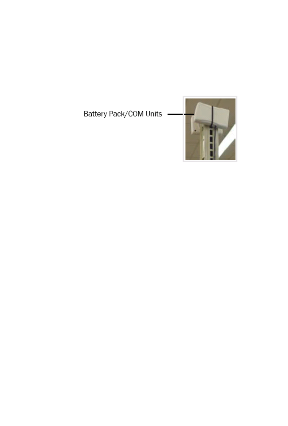
8. Place the Battery Pack/COM Module as follows:
o On the upright above the top shelf.
o Away from store products.
o With the antenna pointing up and away from the shelving.
Figure 14. Installed Battery Pack/COM Unit
9. Attach the Battery Pack/COM Module to the upright with reclosable fasteners.
403-2338-018 13
Installation Guide for In-Store Tracking
6.3. Installing the Cart Module
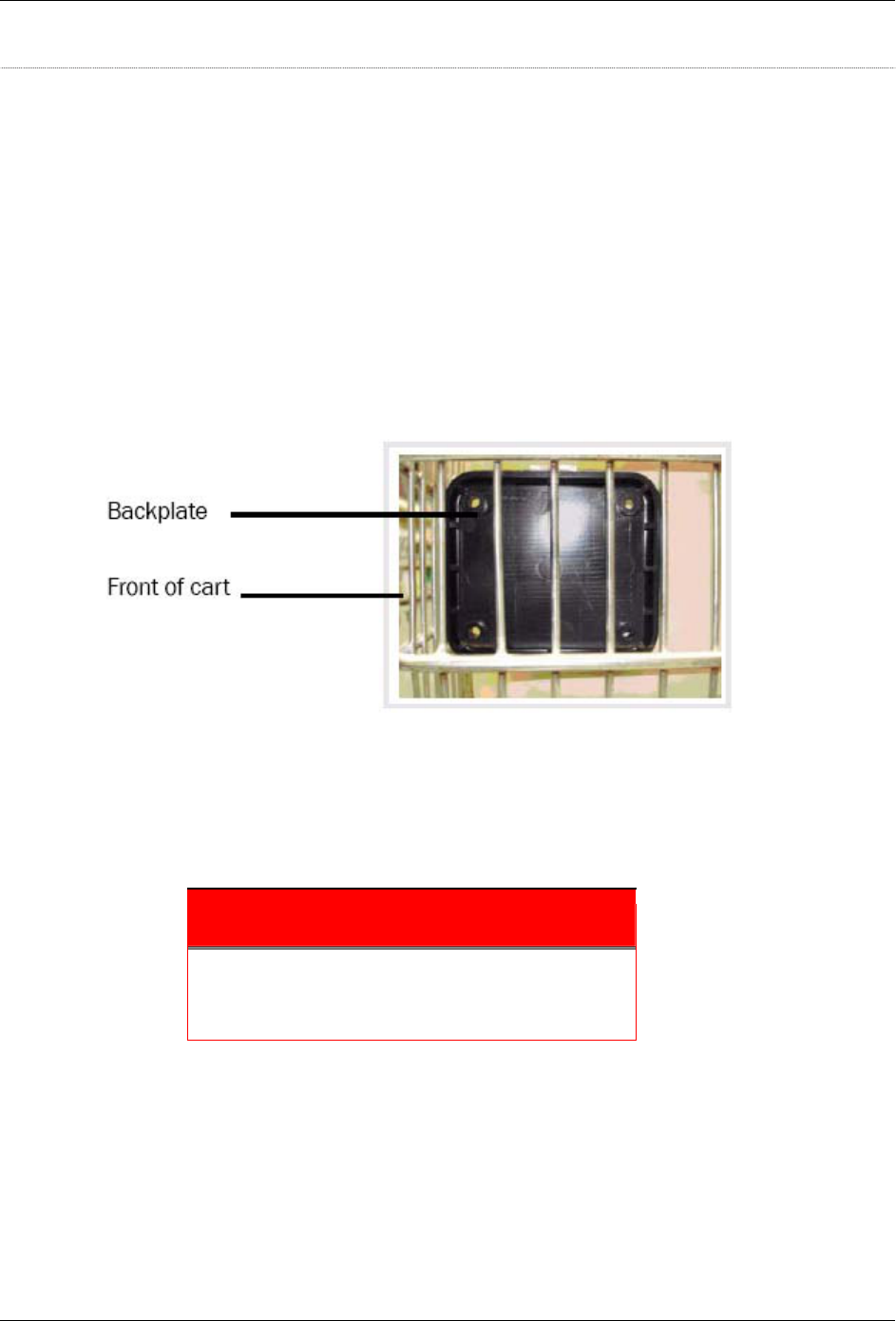
1. Position the back plate so it and the cart module meet the following criteria:
• Back plate—inside the front panel of the cart.
• Cart module—outside the front panel of the cart.
• Both—
o In the lowest section of the front panel and low enough that the module is
protected from coming into contact with another cart when the cart is
stacked or pushed into a corral
o Not near any of the corners on the front of the cart.
o In an area wide enough for the holes in the back plate to be unobstructed.
Figure 15. Back plate mounted on shopping cart
2. Insert the appropriate (long enough) machine screw through the back-plate and
through the corresponding hole in the module and into the hex nut cap. The cap
should fit into the hole in the module enclosure.
3. Secure the machine screw to the hex nut cap.
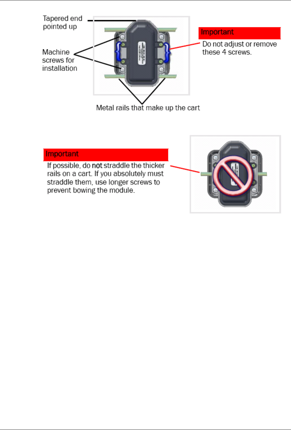
Important
Position the cart module so the tapered end points up
and, if possible, so it is between the thicker rails on the
shopping cart.
14 403-2338-018
Installation Guide for In-Store Tracking
Figure 16. Correct placement of Cart Module between thick cart rails
Figure 17. Wrong placement of Cart Module straddling thick cart rails
4. Repeat until the 4 machine screws are secure. If a machine screw is not long
enough, try one that is ¼” to 1“ longer.
5. Once all machine screws are in place, fully tighten the screws, but do not over-
tighten.
403-2338-018 15

Installation Guide for In-Store Tracking
6.4. Installing the Checkout/Repeater Module
1. Determine a location that does the following:
• Fulfills the assignment on the schematic.
• Provides electrical power to the Checkout/Repeater Module.
2. Using alcohol wipes, clean the areas where you will place the reclosable
fasteners.
3. Attach the module with reclosable fasteners.
4. Ensure the antenna is pointing up.
If the best location is the brackets for a drop ceiling, attach the module with zip
ties.
Figure 18. Checkout/Repeater Module Attached with Zip Ties
Figure 19. Checkout/Repeater Module--Wall Mount
16 403-2338-018

Installation Guide for In-Store Tracking
7. Verification Test
7.1. Required Parts
The parts needed to verify the installation are:
Item
Camera (digital or cell phone)
7.2. Test Procedure
To verify the installation:
1. Aim the lens at the transmitter as though you are taking a photo.
2. Look through the view finder for a flashing LED.
3. To see the other LED, hold the camera so the lens is at a 45° angle to the
transmitter.
4. Look through the view finder for a flashing LED.
403-2338-018 17
Installation Guide for In-Store Tracking
8. Troubleshooting
Each device has a unique serial number, part number, and device ID programmed in
flash at the factory. The Checkout/Repeater Module has an additional IRID
programmed.
When new devices are needed, verify with Back Office that the ID is not in use at the
given installation site.
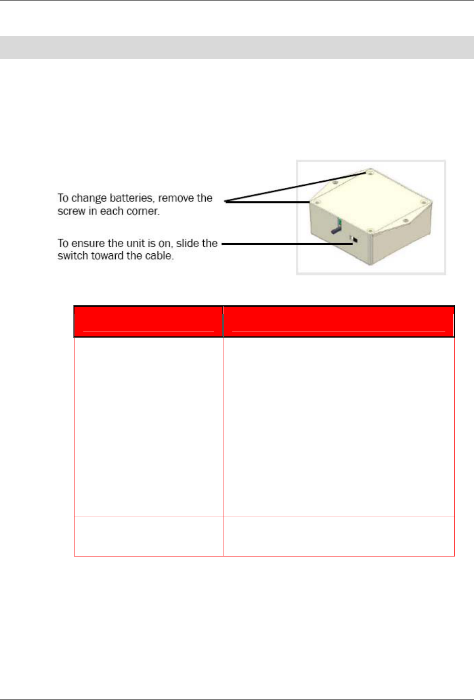
Figure 20. Battery Unit for Shelf Transmitter
If… Do this:
The LED on the Transmitter
Module does not flash in a
camera view finder
Check that the switch is set to on.
a. To turn the unit on, while looking at the unit
from the top, slide the switch toward the
cable.
b. If you decide that the unit was on and is
now off, wait 30 seconds before moving the
switch again.
Check that the cord is firmly attached at both
ends.
Check that the cable is not damaged.
Ensure the batteries are firmly seated.
Ensure all batteries are installed.
Any of the other equipment is
not working
Contact the Operations team.
18 403-2338-018

Installation Guide for In-Store Tracking
Glossary
C
Cart Module Tracking device located on a shopping cart.
Checkout/
Repeater Module
Located at or near the checkout counter, it forwards data from either the
Shelf Receiver or the Cart Modules. In the United States, it contains (off-the-
shelf) 900MHz radio frequency transceiver. In Europe, it contains a 2.4 GHz
transceiver.
I
Installation Module Infrared ID Receiver (for device installation assistance).
IR Infrared.
ISU In-Store Unit - In-Store Personal Computer.
R
RF Radio Frequency.
S
Shelf Receiver Module Counting device located on the shelf opposite the Shelf Transmitter Module.
It includes a Battery/Communications Unit.
Shelf Transmitter Module Dual-purposed module used as a transmitter device for counting/tracking
and, in a special configuration, to signify the end of a shopping trip.
U
uC Micro controller.
403-2338-018 19

Installation Guide for In-Store Tracking
This page intentionally left blank.
20 403-2338-018