The Q Track QT-644-TAG Indoor Location Tag Transmitter User Manual
The Q-Track Corporation Indoor Location Tag Transmitter
User Manual
SafeSpotTM Installation & Configuration
Q0504@G SafeSpot Manual.docx
A. System overview - The SafeSpotTM collision avoidance
system alerts workers to the potential for a vehicle collision around
blind spots and corners.
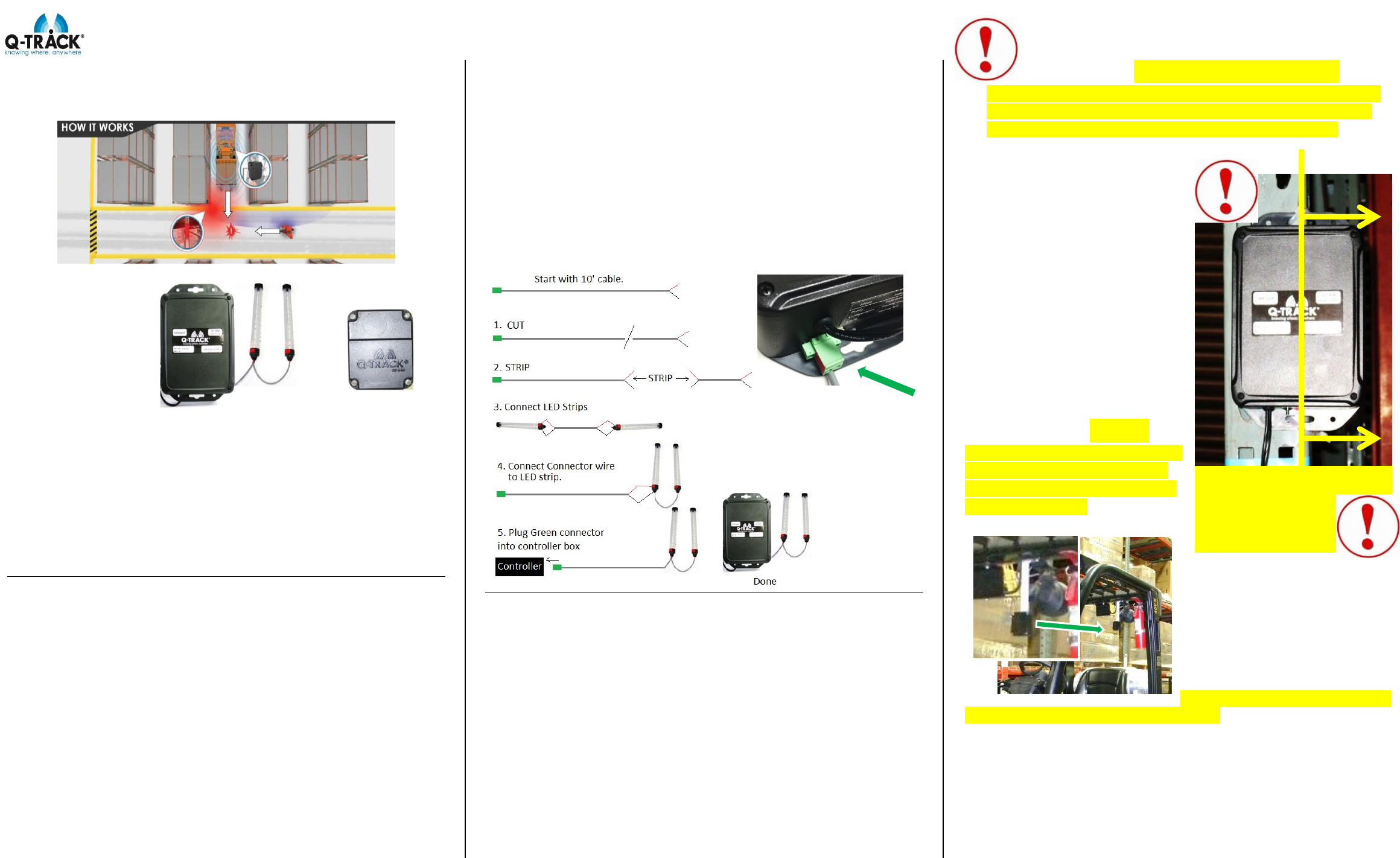
The image at the
right shows the
Controller box,
alarm Warning Light
strips, and the Tag,
respectively.
The Controller box
and light strips
mount to a vertical beam (typically a warehouse rack). There are
two lights to allow viewing from 2 directions. The transmitting Tag
mounts to a forklift or vehicle. When the Tag is detected by the
controller box, the warning light will flash until the Tag is no longer
detected. The detection distance is factory set to detect a Tag
around 25 feet away from the Controller.
You can set the detect range manually as described below. You
can also set the Warning Lights to flash or steady ON. The user
can also select a different output device.
B. Initial Installation
1. Warning Lights – Mount the Warning Light strips slightly
below eye level where pedestrians can see them more easily. Light
strips should be installed facing two directions.
See image on back of sheet. Prepare LED Light Strips prior to
mounting.
1. Connect the light strips together. To do this: determine how
much wire you need between light strips. Cut desired length from
the supplied 10’ (3m) cable. Strip and install cable between LED
Strips. Red tape indicates positive terminal. Connect red to red and
black to black.
2. Connect the set of lights to the light controller box. To do this,
use remaining wire to connect to one of the LED strips. Insert the
red wire from the connector wire in the same hole as the other red
wire from the LED strip. Tighten screw to secure both red wires into
LED strip. Then insert the black connector wire in the same hole as
the other black wire from the LED strip. Tighten screw to secure
both black wires into LED strip.
To install the light strips, peel the clear protective strip from the
Velcro and attach Velcro to beam or post.
If additional wire length is needed, use 2 conductor 22 ga (0.65mm)
jacketed cable meeting UL 2596 or EU Low Voltage Directive
2006/95/EC.
Plug in and screw down the green connector to the bottom of the
Controller.
Q-Track Corp. FCC ID: VJ3-QT-644-TAG. This device complies with Part 15 of the
FCC Rules. Operation is subject to the following two conditions: (1) this device may
not cause harmful interference, and (2) the device must accept any interference
received, including interference that may cause undesired operation. Caution:
Changes or modifications not expressly approved by the party responsible for
compliance could void the user's authority to operate the equipment.
Q-Track Corporation; Model: QT-644; IC: 10503A-TXTAG644.
This device complies with Industry Canada license-exempt RSS standard(s).
Operation is subject to the following two conditions: (1) this device may not cause
interference, and (2) this device must accept any interference, including
interference that may cause undesired operation of the device. This product
meets the applicable Industry Canada technical specifications.
Cet appareil est conforme à Industrie Canada une licence standard RSS exonérés
(s). Son fonctionnement est soumis aux deux conditions suivantes: 1. Cet appareil
ne doit pas provoquer d'interférences 2. Cet appareil doit accepter toute
interférence reçue, y compris les interférences pouvant provoquer un
fonctionnement indésirable de l'appareil. Ce produit est conforme aux
spécifications d'Industrie Canada.
2. Controller - IMPORTANT: For best system
accuracy, offset the Controller as far to the right from the
post as possible. Don’t mount the Controller with metal
behind its right half. Q-Track label must be upright.
Locate the Controller near
available power. The Controller
is supplied with a 9’ (2.7m) cord.
Mount on a vertical metal beam,
rail, or post as shown with user-
supplied screws or cable ties.
Offset brackets are included in
case ambient noise causes
false alarms.
Mount at target height of 7’
Do not wrap wires around unit.
Note: The Controller is fully
insulated so a grounded outlet is
not necessary. The power cord
features a NEMA 1-15P Polarized
plug.
3. Tag - Tags are
required on every vehicle in the
protected area. You must use
the supplied mounting bracket
to mount the Tag.
To mount the Tag, select a clear
area near the top rear of the
vehicle and use a screw to
secure the Tag mounting
bracket. In most cases, a bolt
from an existing light can be
used.
Important! The Tag nameplate
MUST face to the front of the vehicle.
The Tags must be wired to the vehicle power system such that the
Tag is powered ONLY WHEN THE VEHICLE IS ON. The Tag has
no on/off switch – The Tag should always be on when the vehicle
power is on. The supply voltage is 10 VDC to 24 VDC @ 150 mA.
The RED lead is positive. There is a switch and LED indicator on
the top of the Tag – if the Tag is on, the LED will light only when
you press the switch.
OFFSET FROM
METAL
SafeSpotTM Installation & Configuration
Q0504@G SafeSpot Manual.docx
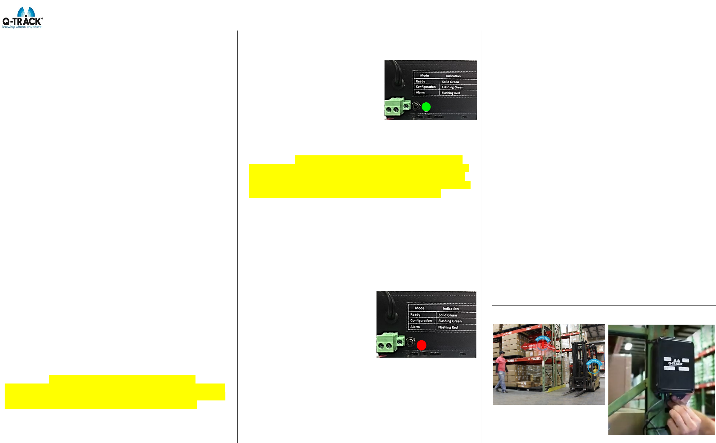
C. Initial System Power Up and Test – After following the
steps above the Safe Spot system is now ready to power up and
test.
Power the vehicle off (Tag will be off). Plug the Controller into a wall
socket. The green status LED should light. Now turn on the power
for the Tag vehicle. Press the button on the Tag -- its LED should
light only as long as the button is pressed (confirms tag is on).
The controller is factory-set to trigger (ALARM) when the Tag is
brought to within about 25 feet (the warning lights should flash red
and the LED on the bottom of the controller should light red).
Separate the controller and tag by more than about 25 feet, and the
warning lights should stop flashing.
Move the tag back and forth from about 25 feet to turn the Warning
Lights on and off a few times to convince yourself how the system
is responding.
If this works and you are satisfied with the trigger distance,
then the Safe Spot is ready to go.
D. Reconfiguring the Trigger Range and Warning Light
modes.
1. Configuring the Trigger Distance – The trigger
distance has been factory set to approximately 25 feet. We have
found 25 feet to be an optimal distance but you can change it if you
wish. The maximum range is about 40 feet, but you may find the
accuracy somewhat less. In this case you may have to experiment
with several settings to get the response you need. The Safe Spot
can also be set to trigger at as little as 20 feet. If you try to set it to
less than 20 feet, it will revert to 20 feet. We have found 20 feet to
be the minimum distance that gives the driver and the pedestrian
sufficient time to react
2. Procedure for Reconfiguring the Trigger Distance
a. IMPORTANT! For tamper prevention, this
procedure must be performed within 5 minutes of power-up. If
a change is needed after that time, you must restart the power-
up timer by unplugging and re-plugging the Controller.
b. Power the Tag-equipped vehicle and move it to the
desired alarm distance (between 20 and 40 feet).
c. Press and hold the button at the bottom of the
Controller. After about 5 seconds, the green status LED will cycle
through slow green flashing to fast green flashing. Release the
button while fast flashing green, then
press and release it one more time. If
the light does not flash, unplug the unit and try
again. You may have to hold the button longer
The Controller is now calibrated to the
desired distance and the status LED
will be lit solid green again. The tag
should now be sitting right at the trigger
threshold.
The Warning Lights should start blinking RED when the Tag moves
within range. IMPORTANT! Test this by moving the vehicle to
all possible avenues of approach and ensure the light triggers.
If the light fails to trigger in any direction, you MUST calibrate
the system to longer distances to assure that it always triggers
at the minimum distance for each avenue of approach.
3. Light Configuration – You can configure the Warning
Lights to either flash or stay on constantly when triggered. The
factory default is flashing. If you prefer the warning lights stay
constant on, follow this procedure:
a. Plug in the Controller. Make sure the rest of this
procedure is completed before the 5-minute turn-on timer expires.
b. Move the Tag close enough to trigger the Controller
(ALERT mode).
c. Press and hold the
button until the status LED flashes
fast red (about 5 seconds).
d. Release the button,
then briefly press it one more time.
The warning lights will turn off for
about 5 seconds, then turn back on
solid.
You can repeat this procedure to
alternatively make the Warning Lights flash again.
4. Additional Lights and Alarms – The green jack for
the Warning Lights can support a maximum of 4 warning lights, or
other customer load, to a maximum of ½ amp. Q-Track offers an
audible siren.
E. Troubleshooting – The status LED on the bottom of the
Controller unit is helpful in determining what the unit is doing.
No light – the Controller is unpowered.
Solid Green – Controller in normal operation, waiting for
trigger event
Solid Red – Controller in ALARM mode (triggered).
Flashing Fast Green – Controller in distance configuration
mode. Press button one more time to set trigger distance.
Flashing Fast Red – controller in warning light configuration
mode. Press button one more time to set Warning Light to flashing
or solid.
Problems you may encounter:
1. Status LED not lit: The Controller is not powered on. Check
the AC power supply.
2. Status LED solid red, but Warning Lights not lit. Wiring
problem to the Warning Lights. Either open-circuited or
connected in reverse. Check red to positive and black to
negative.
3. System Alarms, but Tag not turned on. Another source is
triggering the controller. Plug the Controller into an AC
socket that is far away and try again. Contact Q-Track and
describe the problem further.
Factory RESET: If you attempt to change the configuration of the
distance trigger or the warning light, and believe the settings may
have become scrambled, you can RESET the Controller to its
factory settings: Unplug the Controller. While pressing the button,
plug in the Controller and wait 15-17 seconds before releasing the
button. (Be sure green light is on when button is released). The
Controller is now in as-shipped configuration.
F. Example Installation
Customer Support: 256-489-0075