The Sapling HPB1 914 TO 928 MHz FREQUENCY HOPPING TRANSCEIVER MODULE User Manual Install Manual
The Sapling Company, Inc 914 TO 928 MHz FREQUENCY HOPPING TRANSCEIVER MODULE Install Manual
Contents
- 1. Install Manual
- 2. Users Manual
Install Manual
SMA 1000 Network Repeater
The Sapling Company, Inc.
1633 Republic Road
Huntingdon Valley, PA 19006
215.322.6063 P.
215.322.8498 F.
www.sapling-inc.com
Installation Manual V1

The Sapling Company, Inc.
1633 Republic Road
Huntingdon Valley, PA 19006
215.322.6063 P.
215.322.8498 F.
www.sapling-inc.com
2
Table of Contents
Mounting Instructions
Instructions 3
Wiring Instructions
Instructions 4
Setting Up The Network Repeater
Initial Setup 5
Web Interface
Login 6
Clock Settings 7
Network Settings 8
Network Servers 9
Clock Status 10
Daylight Saving Time 11
Email Alerts 12
Support
Frequently Asked Questions 13
Troubleshooting 13
FCC
FCC Wants You to Know 14
SMA 1000 Series Network Repeater
The Sapling Company, Inc.
1633 Republic Road
Huntingdon Valley, PA 19006
215.322.6063 P.
215.322.8498 F.
www.sapling-inc.com
3
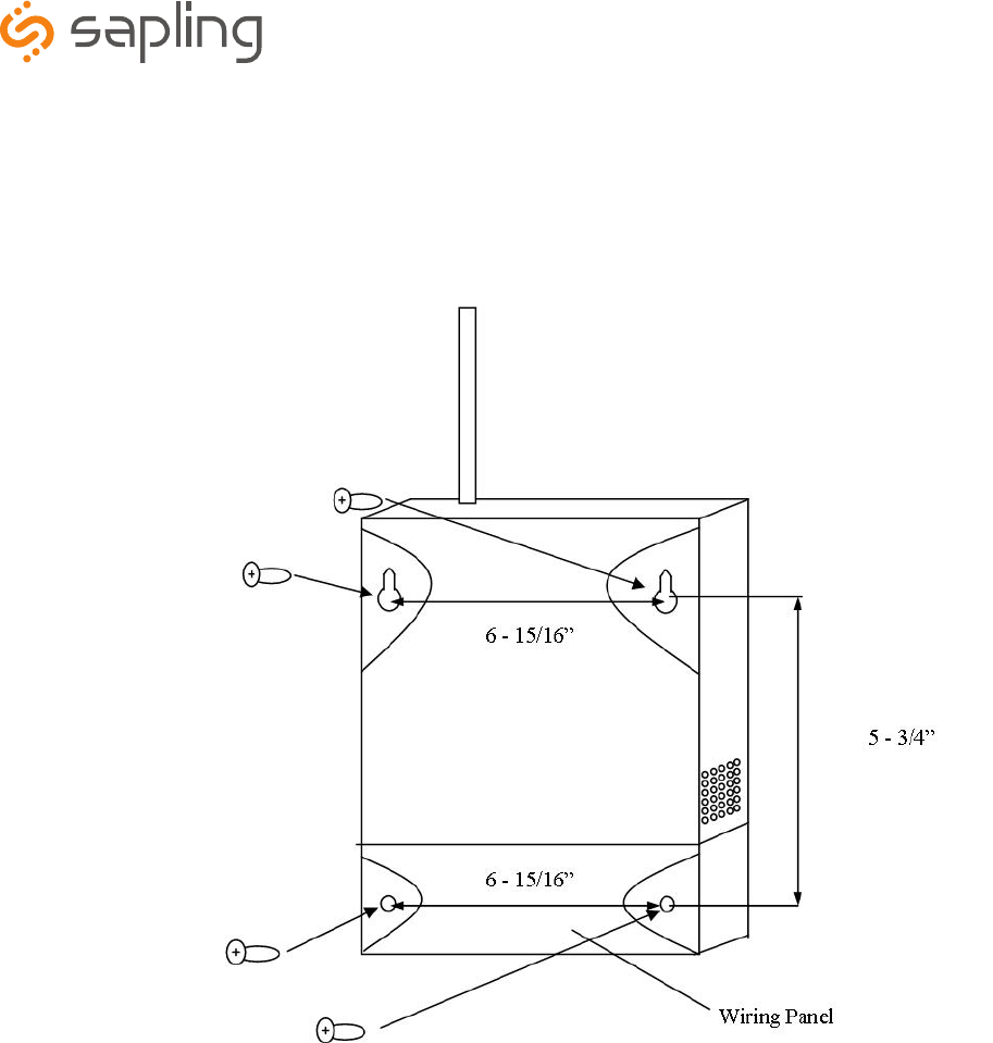
1. Remove the cover of the wiring panel.
2. Mark the four drilling points on the wall based on the drawing above.
3. Drill the holes for the anchors supplied in the mounting kit at the designated markings from step 1.
4. Install the four anchors in the holes that were just drilled.
5. Install the first two screws in the top holes leaving 1/8” of the thread exposed.
6. Line up the top key slots over the screws and lock the master clock into place.
7. Install the bottom screws through the wiring access panel and tighten into place.
8. After all wiring is complete, re-install the wiring panel cover.
Mounting Instructions

The Sapling Company, Inc.
1633 Republic Road
Huntingdon Valley, PA 19006
215.322.6063 P.
215.322.8498 F.
www.sapling-inc.com
4
Wiring Information
Blue Yellow/
Green
Brown
White Green Black
L2 Neutral
Ground
L1 Hot
120VAC @ .2 amp
Europe
USA
The Sapling Company, Inc.
1633 Republic Road
Huntingdon Valley, PA 19006
215.322.6063 P.
215.322.8498 F.
www.sapling-inc.com
5
Setting up the Network Repeater
Initial Setup
1. The Network Repeater is set up to use DHCP by default. Once the Network Repeater is plugged into the switch/router, it will try to get an IP
address automatically.
2. If DHCP is not being used, and a static IP or crossover connection is preferred, then a jumper must be installed on the main board in the
following orientation:
Top View
RJ45 Jack
↓
Jumper must be on
both middle pins for
static IP
3. Static IP - If using a static IP, the IP address will be defaulted to 192.168.0.123. Go to a web browser and type in 192.168.0.123 to load
the web interface. Once this is done, follow the instructions on page 8 to find the Network Settings page. Turn off DHCP and enter the new IP
address and click submit. Then power down the Network Repeater, remove the jumper, and reboot the Network Repeater. To access the web
interface, type in the new IP address in the web browser.
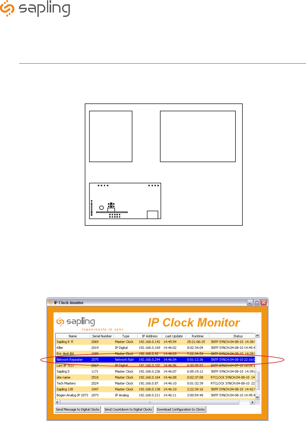
DHCP - If DHCP is being utilized, load the Sapling Monitor software on a PC that is connected to the network. Launch the Monitor.exe file
and follow step 4.
4. Locate the Network Repeater by searching under the “Type” heading. Once it’s located, double click on it to open its web interface.
↓
The Sapling Company, Inc.
1633 Republic Road
Huntingdon Valley, PA 19006
215.322.6063 P.
215.322.8498 F.
www.sapling-inc.com
6
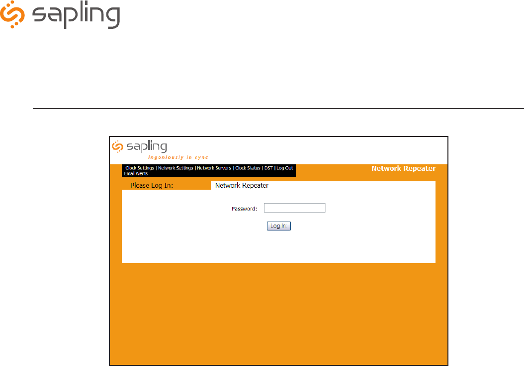
q Password - Type in the password in this field to access the Network Repeater’s Web Interface. The default password
is 6063.
w Log In - Click this button after the password is entered.
Web Interface
Login
q
w
The Sapling Company, Inc.
1633 Republic Road
Huntingdon Valley, PA 19006
215.322.6063 P.
215.322.8498 F.
www.sapling-inc.com
7
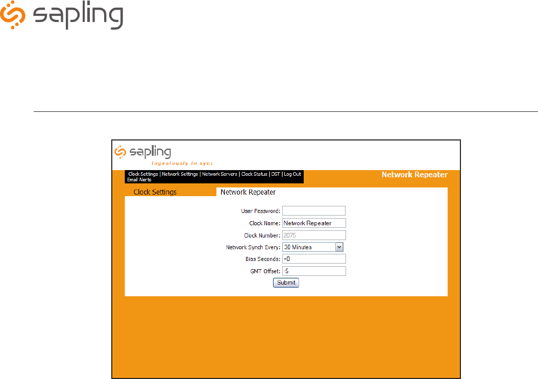
q User Password - To reset the password, type in the new one in this field and click Submit.
w Clock Name - Change the name of the device in this field and click Submit.
eClock Number - This is a read only option. The serial number of the clock is displayed.
rNetwork Synch Every - This option allows the user to set how often the Network Repeater synchronizes to the master
clock.
tBias Seconds - This option offsets the time on the clocks while still receiving an input. This value should match the
value used on the SMA Series Master Clock to ensure synchronized time.
yGMT Offset - This option sets the offset from Greenwich Mean Time. This value should match the value used on the
SMA Series Master Clock to ensure synchronized time.
uSubmit - This button, when clicked, will save and activate all settings on the Clock Settings page.
Web Interface
Clock Settings
q
w
q
w
e
r
t
y
u
The Sapling Company, Inc.
1633 Republic Road
Huntingdon Valley, PA 19006
215.322.6063 P.
215.322.8498 F.
www.sapling-inc.com
8
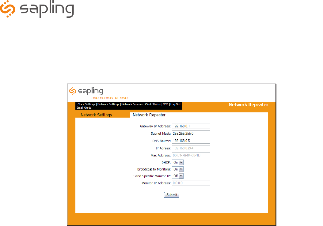
q Gateway IP Address - This field is where the IP address of the Gateway is inserted.
w Subnet Mask - This field sets the Subnet Mask being used.
eDNS Router - This field allows for the DNS router address to be set.
r IP Address - This field will display the IP address that was given by the DHCP server. If DHCP is disabled, then the user will be able to
set the clock’s IP address.
t MAC Address - This read only option is the clock’s physical address.
y DHCP- This setting allows the user to choose whether the clock is on a DHCP server or not.
u Broadcast to Monitors -This setting allows the clock to send out its data in broadcast mode.
i Send Specific Monitor IP - This setting allows the clock to send the IP address to the monitor program through a gateway.
o Monitor IP Address - This field sets the IP address that the clock will use to send it to a particular gateway or subnet.
a Submit - This button, when pressed, clears all of the settings that were changed.
Web Interface
Network Settings
q
w
q
w
e
r
t
y
u
q
w
e
r
t
y
u
i
o
a
The Sapling Company, Inc.
1633 Republic Road
Huntingdon Valley, PA 19006
215.322.6063 P.
215.322.8498 F.
www.sapling-inc.com
9
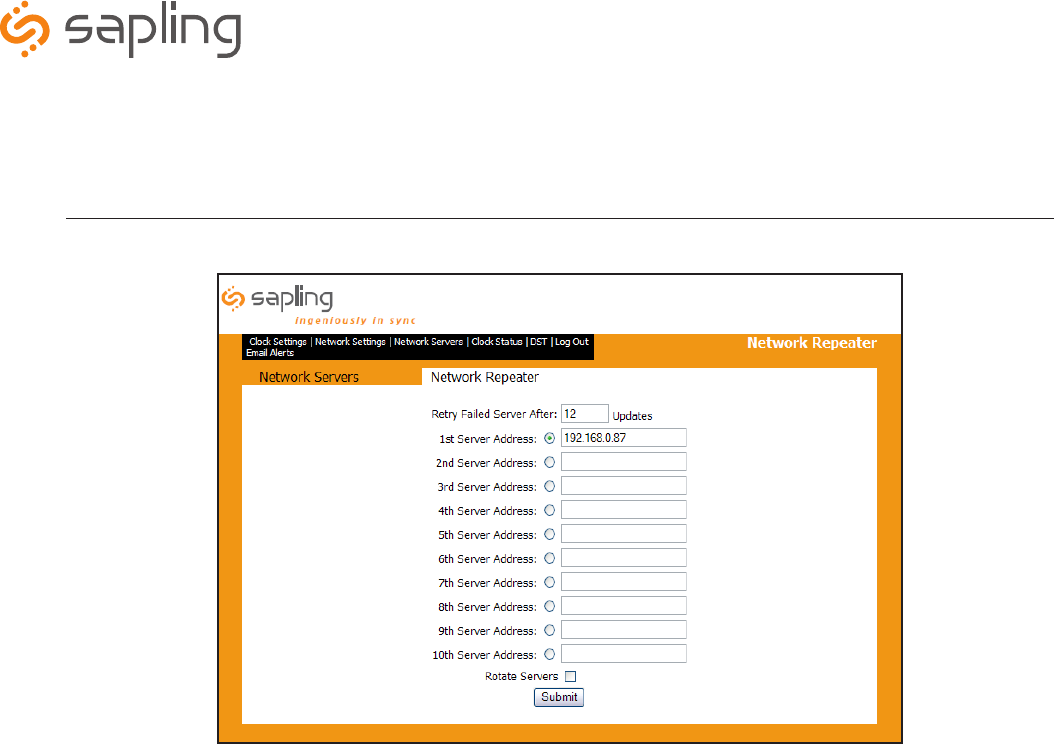
q Retry Failed Server After x Updates - This field will allow the user to set how often it attempts to connect to a server
that has not communicated with the clock. The Network Repeater will only try to synchronize to a SMA Series Master Clock.
w Server Addresses - This field is where the user will enter what IP address that the SMA Series Master Clock is located
for synchronization. The Network Repeater will NOT synchronize to any other time servers but the SMA Series Master
Clock.
eRotate Servers - Not applicable.
r Submit - This button, when clicked, will save all changes on the Network Settings page.
Web Interface
Network Servers
q
w
q
w
e
r
t
y
u
q
w
e
r
t
y
u
i
o
a
q
w
e
r
The Sapling Company, Inc.
1633 Republic Road
Huntingdon Valley, PA 19006
215.322.6063 P.
215.322.8498 F.
www.sapling-inc.com
10
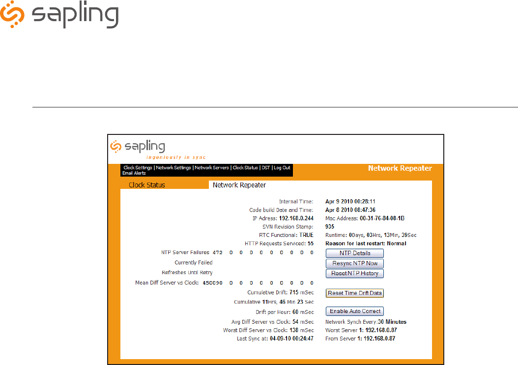
q NTP Details - This button, when clicked, provides additional details about the NTP synchronization.
w Resync NTP Now - This button, when clicked, forces a synchronization with the NTP server.
eReset NTP History - This button, when clicked, resets all the data in the NTP Details window.
r Reset Time Drift Data - This button, when clicked, resets the statistics of the time drifts.
t Enable Auto Correct - This button, when clicked, will calculate the drifts if the NTP Server is synced greater than every 15 minutes. It
will automatically try to correct the time based on the drift statistics.
Web Interface
Clock Status
q
w
q
w
e
r
t
y
u
q
w
e
r
t
y
u
i
o
a
q
w
e
r
t
The Sapling Company, Inc.
1633 Republic Road
Huntingdon Valley, PA 19006
215.322.6063 P.
215.322.8498 F.
www.sapling-inc.com
11
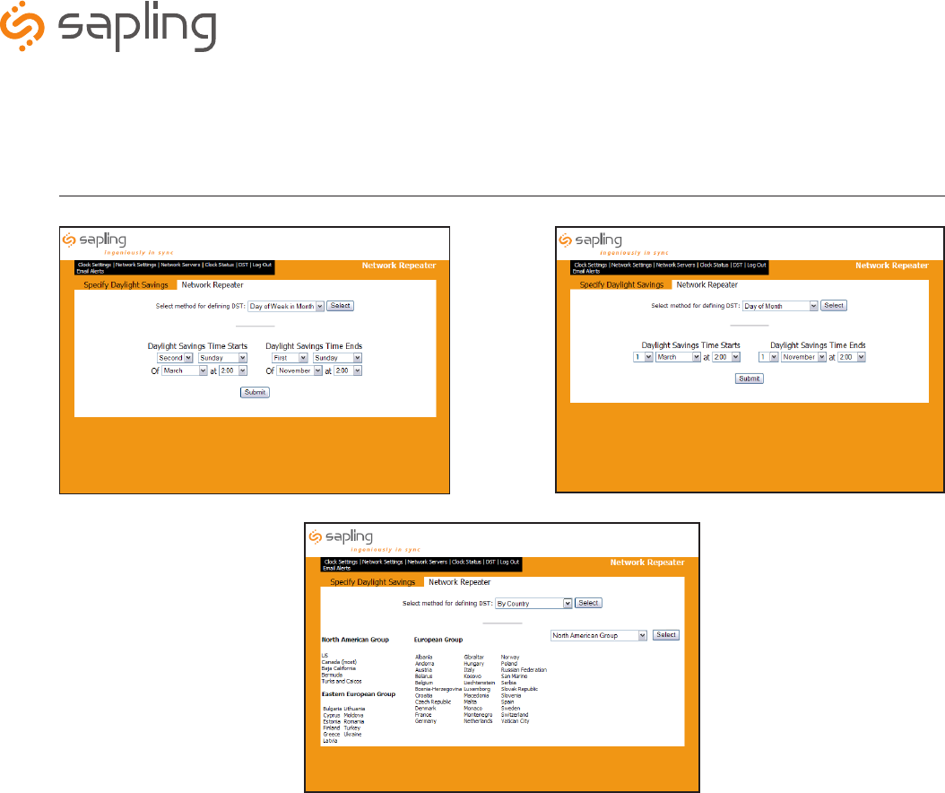
q Day of Week in Month DST Option - This Daylight Saving Time setting is used when the clock is to change time on
the specific day, month and time. This method is typically used in some international countries. Once the option is
selected, click Submit to confirm.
w Day of Month DST Option - This Daylight Saving Time option is used when the clock is to change on a specific day of
the month. Once the option is selected, click Submit to confirm.
eSelecting DST by Country Option - This Daylight Saving Time option is used when the clock is to change time based
on what country its located in. Select the pre-defined group that best fits which DST setting is desired.
IMPORTANT: In order to synchronize correctly with the SMA Series Master Clock, use the same setting as the SMA
Series Master Clock that is being used as the primary time source.
Web Interface
Daylight Saving Time
q
w
q w
e
The Sapling Company, Inc.
1633 Republic Road
Huntingdon Valley, PA 19006
215.322.6063 P.
215.322.8498 F.
www.sapling-inc.com
12
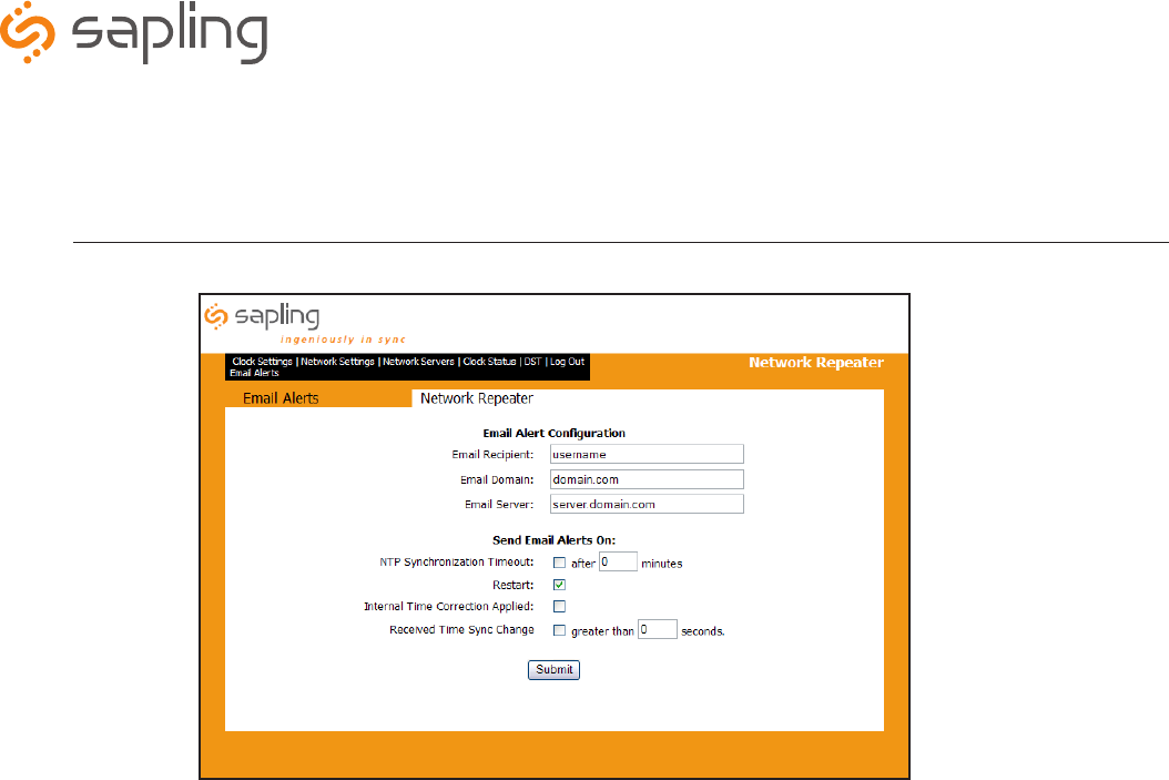
q Email Recipient - This field is where the user name of the email recipient will be inserted. Do not enter the domain and suffix.
(correct: johnsmith) (incorrect: johnsmith@domain.com)
w Email Domain - This field is where the user will enter the domain name of the email server. (i.e. domain.com)
eEmail Server - This field is where the email server address will be placed. (i.e. server.domain.com
r Email Alert: NTP Synchronization Timeout - When checked, this will send an alert when the clock hasn’t received a time
synchronization.
t Email Alert: Restart - When checked, this will send an alert when the clock has been reset.
y Email Alert: Internal Time Correction Applied - When checked, this will send an alert when the clock time has been changed
(only applies if receiving NTP sync greater than every 15 minutes.
u Email Alert: Received Time Sync Change - When checked, this will send an alert when time that is synchronized is greater than x
seconds.
i Submit - This button, when clicked, will save all changes on the Email Alerts page.
Web Interface
Email Alerts
q
w
e
r
t
y
u
i

The Sapling Company, Inc.
1633 Republic Road
Huntingdon Valley, PA 19006
215.322.6063 P.
215.322.8498 F.
www.sapling-inc.com
13
Frequently Asked Questions
Where is the best location for the Network Repeater to be mounted?
Usually, the hallway is the best location because it is mostly open space in typical applications.
How far can the Network Repeater transmit the wireless signal?
The Transceiver can transmit up to 2000 meters in open space.
Will the Repeater have interference from cordless or cellular phones?
No, because with Sapling’s innovative frequency-hopping technology, interference will not occur. The repeater switches frequencies automatically
when the receiver and transmitter is open, thus interference is avoided.
Can analog wireless clocks be combined with digital wireless clocks?
Absolutely. The analog and digital wireless clocks are designed to work together, whether the clocks are running on battery (analog wireless clock
only), 24 volts or 110 volts.
My power source is 220 volts. Can the Network Repeater be powered on that voltage?
Yes, the Repeater can work on 110 volts/50-60 Hz or 220 volts/50-60 Hz.
How often does the Network Repeater send the wireless signal?
The Network Repeater sends out the signal once a minute.
Can the Network Repeater receive time from other devices besides the Sapling SMA Series Master Clock?
No, the Network Repeater only receives time from the SMA Series Master Clock.
Troubleshooting
The clocks aren’t receiving the signal. What should I do?
Make sure that the Repeater is in a place where the signal can be transmitted in open space.
What should I do if the Repeater is not powering up?
Measure the voltage between pins L1 & L2. The voltmeter should read 85 - 135 VAC between the hot and the neutral.
What do I do if I cannot get an IP address from the DHCP server and want to use a static IP instead?
See page 5 for instructions on setting the Network Repeater to use a static IP address.
Support

The Sapling Company, Inc.
1633 Republic Road
Huntingdon Valley, PA 19006
215.322.6063 P.
215.322.8498 F.
www.sapling-inc.com
14
This equipment has been tested and found to comply with the limits for a Class B digital device, pursuant to Part 15 of the FCC
rules. These limits are designed to provide reasonable protection against harmful interference in a commercial installation.
This equipment generates, uses and can radiate radio frequency energy and, if not installed and used in accordance with the
instructions, may cause harmful interference to radio communications. However, there is no guarantee that interference will
not occur in a particular installation. If this equipment does cause harmful interference to radio or television reception, which
can be determined by turning the equipment off and on, the user is encouraged to try to correct the interference by one or
more of the following measures:
a) Reorient or relocate the receiving antenna.
b) Increase the separation between the equipment and receiver.
c) Connect the equipment to an outlet on a circuit different from which the receiver is connected.
d) Consult the dealer or an experienced radio/TV technician.
FCC WARNING
Modifications not expressly approved by the manufacturer could void the user authority to
operate the equipment under FCC Rules.
Note: This equipment must be installed by professional installers only. For precautionary measures, FCC requires a minimum
distance of 15cm from the clock to constant human physical exposure. The antenna has a maximum gain of 2dB.
This device complies with part 15 of the FCC Rules. Operation is subject to the following two conditions: (1) This device may not cause harmful
interference, and (2) this device must accept any interference received, including interference that may cause undesired operation.
NOTE: THE MANUFACTURER IS NOT RESPONSIBLE FOR ANY RADIO OR TV INTERFERENCE CAUSED BY UNAUTHORIZED MODIFICATIONS TO THIS
EQUIPMENT. SUCH MODIFICATIONS COULD VOID THE USER’S AUTHORITY TO OPERATE THE EQUIPMENT.
FCC Wants You to Know