The Sapling SAL002 SAL-2 SERIES WIRELESS CLOCK User Manual USERS MANUAL
The Sapling Company, Inc SAL-2 SERIES WIRELESS CLOCK USERS MANUAL
UserManual.wiki
>
The Sapling
>
SAL002 User Manual
USERS MANUAL
Navigation menu
Upload a User Manual
Namespaces
Wiki Guide
HTML
PDF
Info
Views
User Manual
Discussion / Help
Navigation
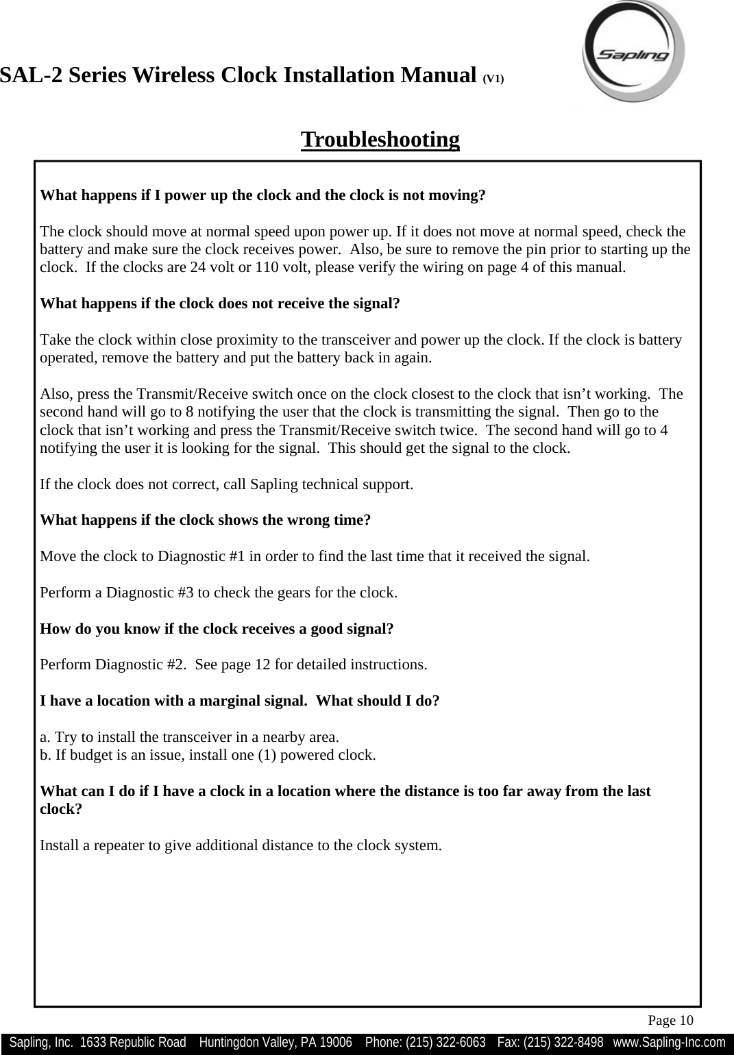
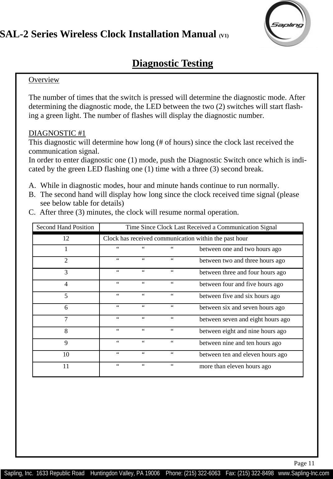
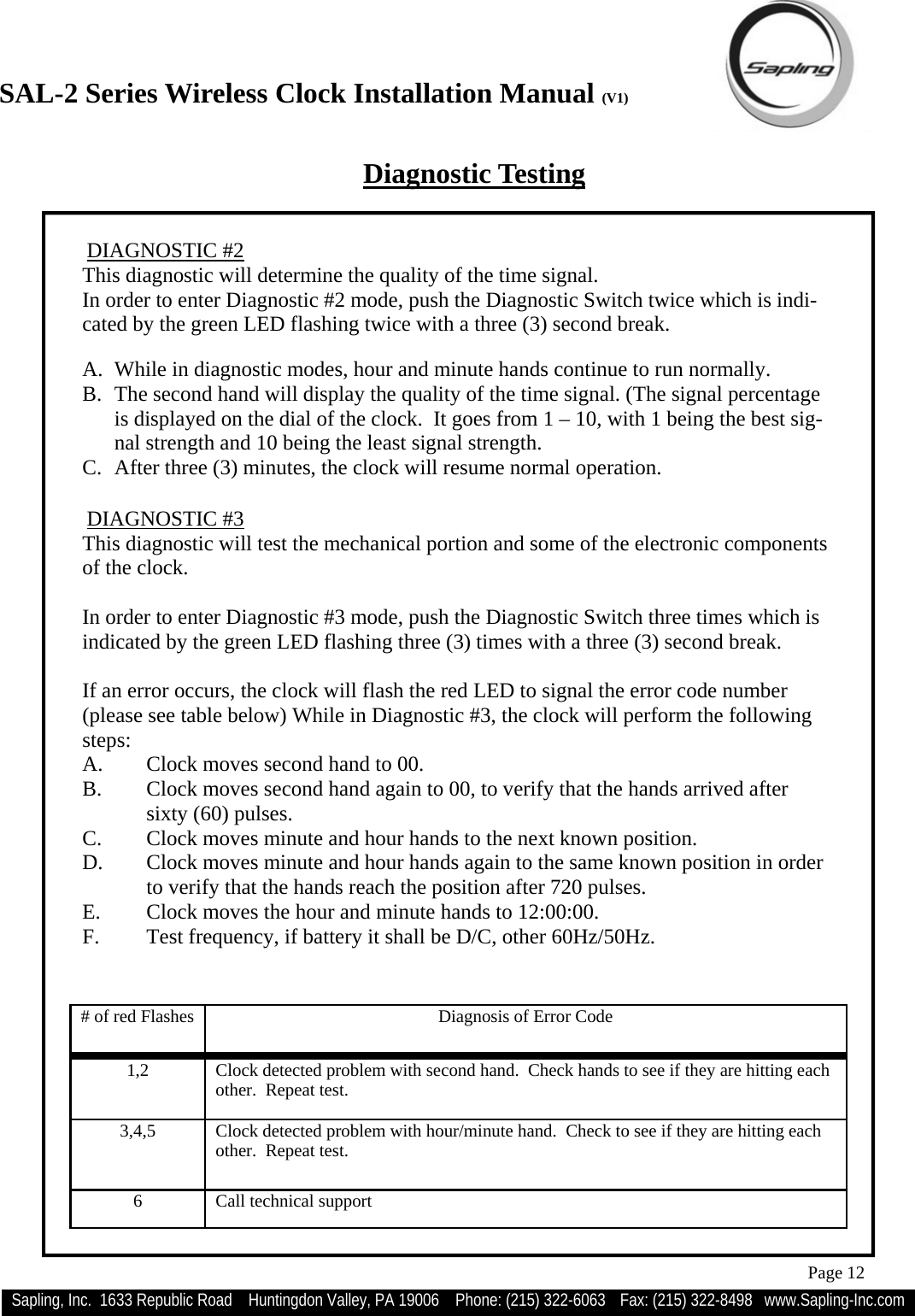
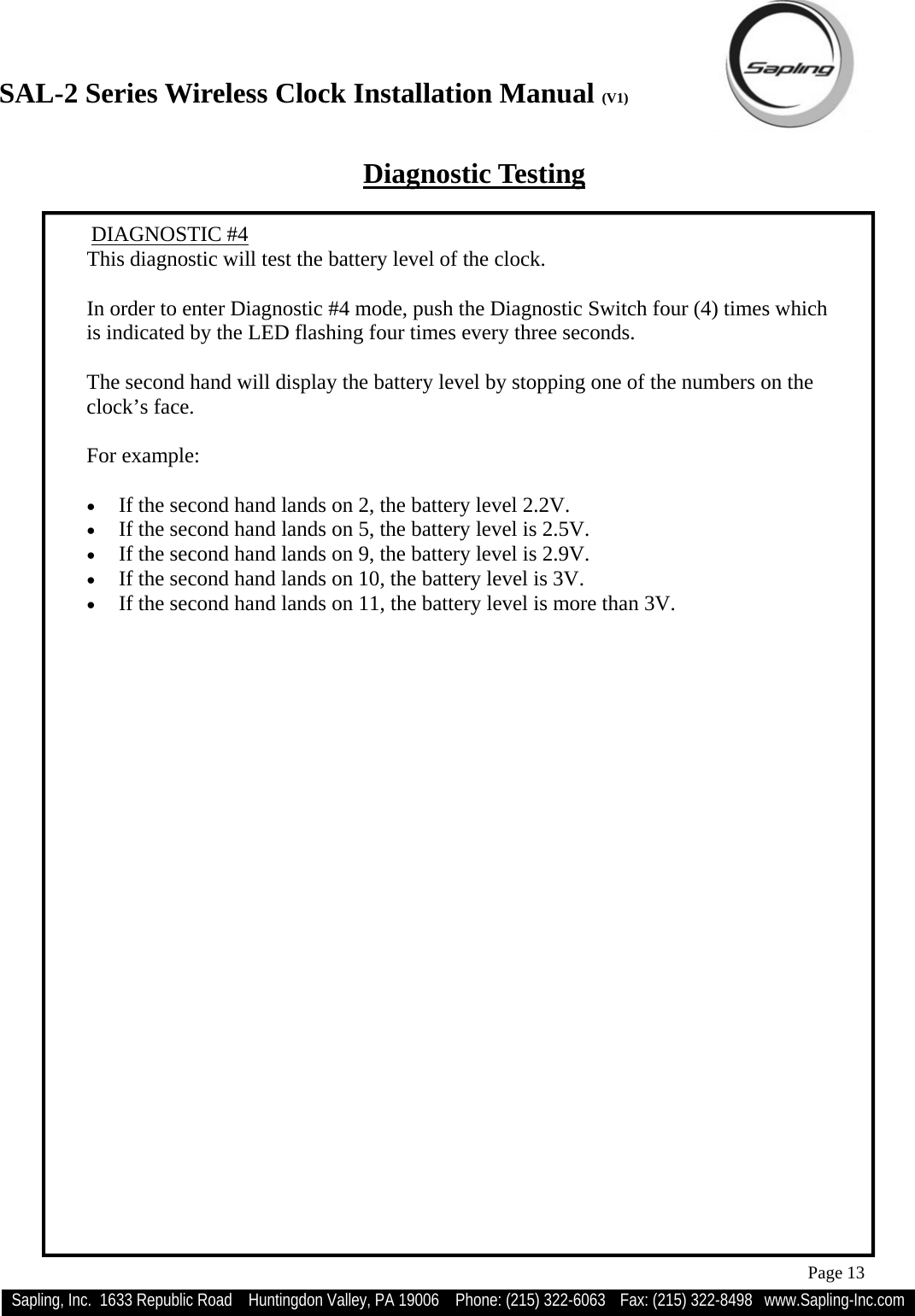
![SAL-2 Series Wireless Clock Installation Manual (V1) Sapling, Inc. 1633 Republic Road Huntingdon Valley, PA 19006 Phone: (215) 322-6063 Fax: (215) 322-8498 www.Sapling-Inc.com Page 9 Frequently Asked Questions What battery size do I use for the wireless clock? The batteries required are two (2) “D” cell battery. The recommended battery type is “Duracell: Procell [D] size”. Will the clock cause interference with any of my other wireless devices? No, the SAL Series wireless clock works on 915 - 928 MHz frequency-hopping technology. The clock switches frequencies automatically when the receiver and transceiver is open, thus interfer-ence is avoided. Is there any advantage to a powered clock system as opposed to a battery operated system, assuming a single transceiver is in the building? The powered wireless clock receives and transmits every minute and in locations where the signal is marginal, the likelihood of receiving a signal increases because of the frequent transmission rate. What is the advantage of having multiple transceivers on a powered clock system? Assuming the distances between the clocks is sufficient to receive the signal with an analog clock, there is no advantage of multiple transceivers on a powered system. How long does it take for the clock to receive a signal? Upon power up of the clock, the receiver will be turned on for a ten (10) minutes until the signal is acquired. If the user wishes to manually look for the signal, press the Transmit/Receive switch twice on the movement. Can the clocks be set manually to display the correct time at installation (as a temporary measure until the master clock is installed)? SAL clocks can NOT be set manually.](https://usermanual.wiki/The-Sapling/SAL002/User-Guide-1136976-Page-9.png)