The Watt Stopper d b a Qmotion 140704 ZigBee RFIC User Manual
Qmotion Incorporated ZigBee RFIC
User Manual

1
PRELIMINARY
ZigBee Pro Honeycomb Automated Shade
Operation Manual
Revision A
12/29/2015

2
PRELIMINARY
TO OUR CUSTOMER
It is our mission to bring you a high quality product that fits our high standards for in-
novation, beauty and simplicity. To do so we have released our Second Generation QMo-
tion® Automated Roller Shade to bring you a great shade experience. This design has many
features that you may or may not have noticed that will make your shade more reliable and
ready for our future development plans.
If this is your first time purchasing QMotion® shades, we invite you to view our first
time setup document located at the web address below:
http://qmotionshades.com/support.php
QMotion® Customer Service
Contact us Monday-Friday 8:00a.m. – 6:00p.m. (U.S. Central Time)
1-877-849-6070

3
PRELIMINARY
Table of Contents
ZigBee Pro Specifications ……………………………………………………………….…………………...#
ZigBee Coordinator/Router Programming Instructions..……………………………….………………….#
ZigBee Honeycomb Cellular Shade Programming Instructions...………………………….…………….#
ZigBee Remote Programming Instructions... ……………………………………………….……………..#
Glossary………….……………………………………………………………………….……………………#
Revision History... ……………………………………………………………………….……………………#
4
PRELIMINARY
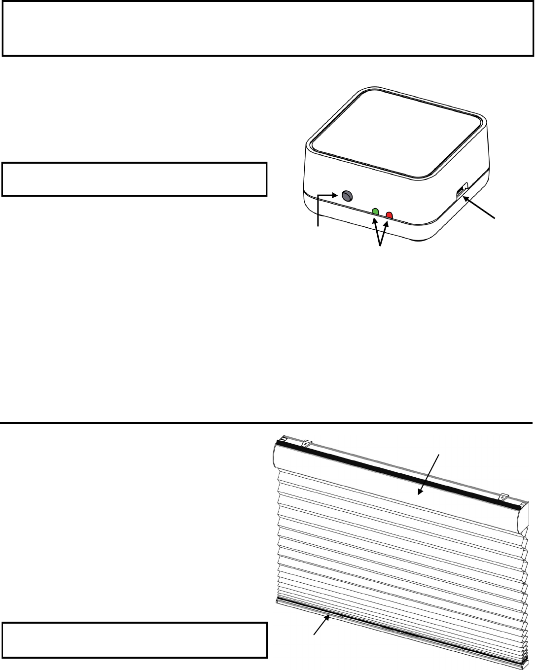
ZigBee Coordinator / Router Programming Instructions
CREAT A NEW NETWORK (Coordinator)
1. POWER the COORDINATOR/ROUTER by connecting
__the power supply using the MICRO USB cable provided
2. PRESS and HOLD the NETWORK button until the
__GREEN LED illuminates (GREEN LED illumination
__indicates the network is active)
Network
Button
Micro USB
Port
JOIN AN EXISTING NETWORK (Router)
1. PRESS the NETWORK button on the NETWORK
__COORDINATOR or any ROUTER already connected to
__the coordinator network
__(RED LED will pulsate on all coordinator/routers present
__on the coordinator network when open to joining)
2. PRESS the NETWORK button on the ROUTER that will
__join the coordinator network
__(GREEN LED will illuminate when connected to the
__coordinator network)
QMotion ZigBee
Coordinator/Router
This first device that establishes the network is designated
as the NETWORK COORDINATOR
LEAVE A NETWORK (Router)
1. PRESS the NETWORK button on the ROUTER three (3)
__times quickly
__(GREEN LED will turn OFF when not connected to a
__network)
READ AND UNDERSTAND EACH SECTION BEFORE PERFORMING REQUIRED STEPS
Refer to appropriate user manual whenever a QMotion Coordinator/Router is NOT USED to establish the coordinator
network. Instructions for allowing Routers and End Devices to join the coordinator network will vary by manufacturer.
LED
JOIN A NETWORK (Honeycomb Shade)
1. REMOVE the FASCIA cover to expose the battery holder
2. PULL the BATTERY TAB or POWER CYCLE the shade
__(See POWER CYCLE section)
3. TUG the shade hembar 10-20 inches
__(Shade will JOG in response)
The shade is now joined to the coordinator network.
The GREEN LED on networked devices will FLASH for 1
second when a new device joins the coordinator network
Fascia Cover
Hembar
ZigBee Honeycomb
Shade
ZigBee Honeycomb Programming
Instructions
5
PRELIMINARY
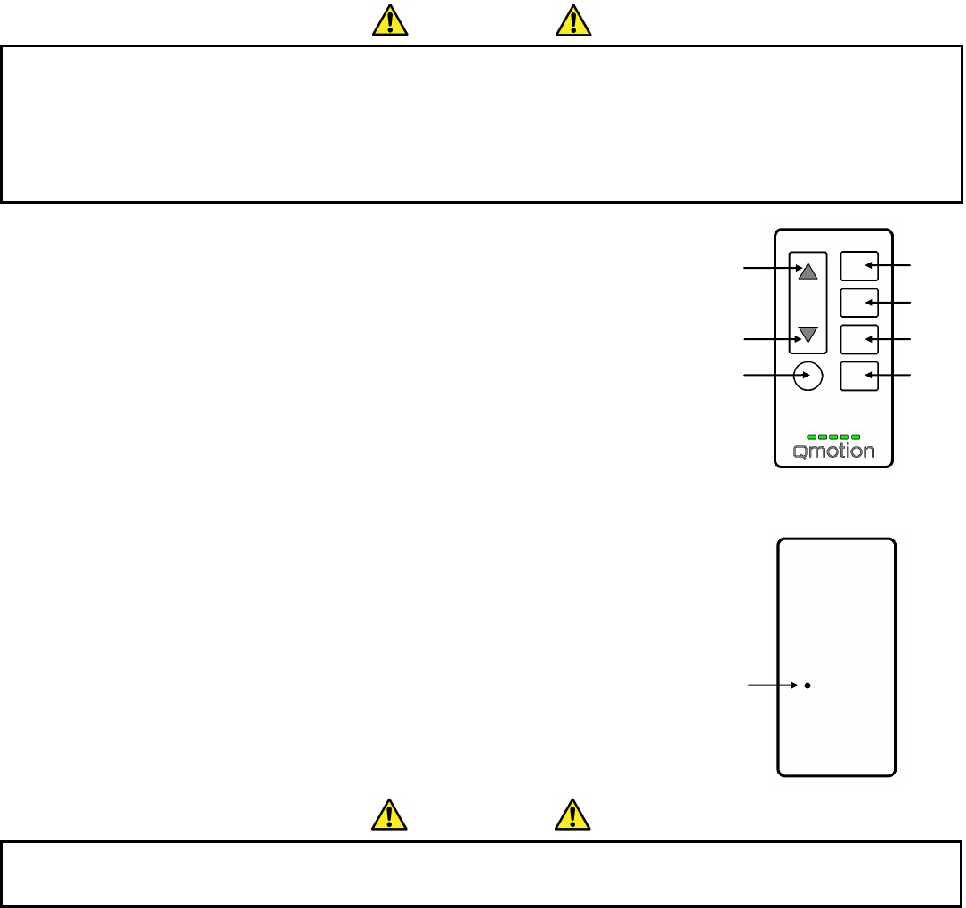
ZigBee Remote Programming Instructions
12345
CH
Front
Back
UP
DOWN
CHANNEL
20%
40%
60%
80%
PROGRAM
Pin Hole
READ AND UNDERSTAND EACH SECTION BEFORE PERFORMING REQUIRED STEPS
Most programming instructions start with the shade in the upper limit position. If a remote is paired to the shade, pushing
the UP button will send the shade to the Upper Limit Position. If no remote is paired to the shade, remove the Honey-
comb fascia, slide out the motor and battery holder and push the shade up manually. Replace the motor and fascia.
JOG is a short up then down shade movement.
IMPORTANT
FIRST TIME SETUP
1. INSTALL SHADE following appropriate installation instructions
2. Remove battery enclosure cover and pull the plastic battery tab
3. On power-up the shade automatically enters PAIRING / LEARN MODE
4. Use a paperclip to PRESS the PROGRAM button on back of the remote
(The channel LEDs will scroll back and forth when in program mode)
5. PRESS and HOLD the UP button until Shade moves downward
PAIRING / LEARNING NEW REMOTES (or Channel)
(Must start using paired remote with shade at Upper Limit Position)
STEPS 1- 3 use paired remote
1. Use a paperclip to PRESS the PROGRAM button on back of the remote
(The channel LEDs will scroll back and forth when in program mode)
2. PRESS and HOLD the UP button until Shade moves downward
3. TUG the shade 6-10 inches (Shade will JOG in response)
STEPS 4- 6 use unpaired remote
4. PRESS the CHANNEL button until desired Channel is lit by GREEN LED
5. Use a paperclip to PRESS the PROGRAM button on back of the remote
(The channel LEDs will scroll back and forth when in program mode)
6. PRESS the UP button (Shade will move to Upper Limit Position in response)
SETTING UPPER AND LOWER LIMITS / LEARNING A NEW POSITION
1. PRESS the (UP, DOWN, or PERCENT) button that will be programmed (Shade will move to selected position)
2. PRESS and HOLD the same (UP, DOWN, or PERCENT) button until shade JOGS
3. TUG shade 6-10 inches (Shade will JOG in response)
4. ADJUST shade to desired position ( Use UP/DOWN buttons or manually adjust shade by hand)
5. PRESS and HOLD the same (UP, DOWN, or PERCENT) button (Shade will JOG when learned)
IMPORTANT
Lower Limit Position must be set prior to using the PERCENT positions (20%, 40%, 60%, 80%). These positions are
calculated based on the Lower Limit Position of the shade.
6
PRELIMINARY
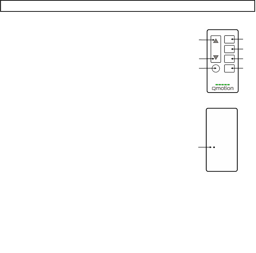
12345
CH
Front
Back
UP
DOWN
CHANNEL
20%
40%
60%
80%
PROGRAM
Pin Hole
DELETE / UNLEARN A REMOTE (or Channel)
(Shade at Upper Limit Position)
1. Use a paperclip to PRESS the PROGRAM button on back of the remote
(The channel LEDs will scroll back and forth when in program mode)
2. PRESS and HOLD the UP button until Shade moves downward
3. TUG the shade 6-10 inches (Shade will JOG in response)
4. PRESS the CHANNEL button until desired Channel is lit by GREEN LED
5. Use a paperclip to PRESS the PROGRAM button on back of the remote
(The channel LEDs will scroll back and forth when in program mode)
6. PRESS the DOWN button
(Shade will JOG, move to Upper Limit Position, and then JOG again)
SPECIAL LEARN COMMAND
(Must use an unpaired remote with shade at Upper Limit Position)
1. Use a paperclip to PRESS the PROGRAM button on the back of the remote
(The channel LEDs will scroll back and forth when in program mode)
2. PRESS and HOLD the CHANNEL button until the shade moves
3. TUG the shade 6-10 inches (The shade will JOG in response)
4. Use a paperclip to PRESS the PROGRAM button on the back of the remote
(The channel LEDs will scroll back and forth when in program mode)
5. PRESS the UP button
(The shade will travel to the Upper Limit Position to confirm learn command)
BATTERY CHANGE / POWER CYCLE
1. REMOVE the FASCIA cover to expose the battery holder
2. REPLACE batteries with a new set of fresh D-Cell Alkaline batteries
3. POWER CYCLE is performed by removing a single battery, and then tugging the shade 5 inches
4. INSERT batteries and REPLACE FASCIA cover
FACTORY (MASTER) RESET (Will remove ALL paired remotes, EXCEPT remote and channel used during reset)
(Shade at Upper Limit Position)
1. Use a paperclip to PRESS the PROGRAM button on back of the remote
(The channel LEDs will scroll back and forth when in program mode)
2. PRESS and HOLD the DOWN button until shade moves downward
3. TUG the shade 6-10 inches (Shade will JOG in response)
4. Use a paperclip to PRESS the PROGRAM button on back of the remote
(The channel LEDs will scroll back and forth when in program mode)
6. PRESS the UP button (Shade will move to Upper Limit Position in response)
READ AND UNDERSTAND EACH PROGRAMMING SECTION BEFORE PERFORMING REQUIRED STEPS

7
PRELIMINARY
Fascia
The removable covering that hides the internal shade components and battery holder.
Long Tug
Tug shade hembar more than 2 inches. A long tug will cause the shade to stay at the position
it was tugged to. Two long tugs done within 10 seconds of each other will send the shade to
the upper limit position.
Micro Tug
Tug shade hembar up to 1 inch. A micro tug will send the shade to the next highest position
Short Tug
Tug shade hembar 1 to 2 inches. A short tug will send the shade to the upper limit position
Hardstop
A hardstop is the mechanical means by which the shade identifies the maximum upper limit.
ZigBee Coordinator
The coordinator establishes the network, and there is exactly one per network. (Cannot be
battery powered)
ZigBee End Device
End Devices cover a wide range of products including QMotion Battery Operated Shades.
These devices do not relay data, but consume less power allowing for battery operation.
ZigBee Router
Routers act as intermediate nodes within the network, relaying data between devices.
Routers also act as ranger extenders to the network. (Cannot be battery powered)
Glossary

8
PRELIMINARY
Revision History
Revision A - 12/29/15
FCC
Warning: Changes or modifications to this device not expressly approved by QMotion® Incorporated -Advanced Shad-
ing Systems could void the user’s authority to operate the equipment.
NOTE: This equipment has been tested and found to comply with the limits for a Class B digital device, pursuant to
Part 15 of the FCC Rules. These limits are designed to provide reasonable protection against harmful interference in a
residential installation. This equipment generates, uses, and can radiate radio frequency energy and, if not installed
and used in accordance with the instructions, may cause harmful interference to radio communications. However,
there is no guarantee that interference will not occur in a particular installation. If this equipment does cause harmful
interference to radio or television reception, which can be determined by turning the equipment off and on, the user is
encouraged to try to correct the interference by one or more of the following measures:
• Reorient or relocate the receiving antenna.
• Increase the separation between the equipment and receiver.
• Connect the equipment into an outlet on a circuit different from that to which the receiver is connected.
• Consult the dealer or an experienced radio/TV technician for help.
RF Exposure
This equipment complies with FCC radiation exposure limits set forth for an uncontrolled environment. This equipment
should be installed and operated with minimum distance 20cm between the radiator and your body. This transmitter
must not be co-located or operating in conjunction with any other antenna or transmitter.
INDUSTRY CANADA
This device complies with Industry Canada licence-exempt RSS standard(s). Operation is subject to the following two
conditions: (1) this device may not cause interference, and (2) this device must accept any interference, including inter-
ference that may cause undesired operation of the device.
Le présent appareil est conforme aux CNR d'Industrie Canada applicables aux appareils radio exempts de licence.
L'exploitation est autorisée aux deux conditions suivantes: (1) l'appareil ne doit pas produire de brouillage, et (2)
l'utilisateur de l'appareil doit accepter tout brouillage radioélectrique subi, même si le brouillage est susceptible d'en
compromettre le fonctionnement.
RF Exposure
Cet équipement est conforme aux limites ďexposition aux radiations dans un environnement noncontrôlé. Cet équipe-
ment doit être installé et utilisé à distance minimum de 20cm entre le radiateur et votre corps. Cet émetteur ne doit pas
être co-localisées ou opérant en conjunction avec tout autre antenne ou transmetteur.