The Watt Stopper d b a Qmotion EX11059 Qmotion Qconnect User Manual 11 0364 Exhibit Cover
HomeRun Holdings Corp. Qmotion Qconnect 11 0364 Exhibit Cover
Manual

5015 B.U. Bowman Drive Buford, GA 30518 USA Voice: 770-831-8048 Fax: 770-831-8598
Certification Exhibit
FCC ID: X6P-EX11059
IC: 8832A-EX11059
FCC Rule Part: 15.231
IC Radio Standards Specification: RSS-210
ACS Report Number: 11-0364.W06.11.A
Manufacturer: HomeRun Holdings
Model: Q0244
Manual

Qmotion Qconnect
Operating Guide
Instructions

Qmotion Qconnect
HomeRun Holdings Corporation
3400 Copter Road
Pensacola, FL 32514
Phone 877.849.6070 • Fax 850.208.3404
Qmotion@homerunholdings.com

Table of Contents
INTRODUCTION....................................................................... 1
REGULATORY STATEMENTS ................................................ 1
PRECAUTIONS STATEMENT.................................................. 3
CHECKING SUPPLIED ACCESSORIES.................................. 4
IDENTIFYING THE PARTS ...................................................... 5
CONNECTOR PIN OUT............................................................ 6
ASSEMBLY............................................................................... 9
MOUNTING INSTRUCTIONS................................................... 9
LED ACTIVITY .......................................................................... 9
ROTARY SELECTOR............................................................... 9
THEORY OF OPERATION ..................................................... 11
INTERFACE CABLE OPTIONS.............................................. 12
SELECTING THE INTERFACE (RS232, RS485, DRY
CONTACT).............................................................................. 13
RS232 OPERATION ............................................................... 14
RS485 OPERATION ............................................................... 16
DRY CONTACT OPERATION ................................................ 18
APPENDIX - A – button code list ........................................... 19

QCONNECT INSTRUCTIONS
1
INTRODUCTION
omerun Holdings Qmotion Qconnect is a multifunctional device. It uses
Qmotion RF technology and both dry contact and serial interfaces to act as
a shade controller in your installation. This manual will guide you through
the setup and understanding of your Qconnect functions. Once installed,
your Qmotion Qconnect can be used to control various types of Qmotion shades.
FCC COMPLIANCE
Warning: Changes or modifications to this device not expressly approved by
HomeRun Holdings Corp. could void the user’s authority to operate the
equipment.
Note: This equipment has been tested and found to comply with the limits for a
Class B digital device, pursuant to Part 15 of the FCC Rules. These limits are
designed to provide reasonable protection against harmful interference in a
residential installation. This equipment generates, uses, and can radiate radio
frequency energy and, if not installed and used in accordance with the instructions,
may cause harmful interference to radio communications. However, there is no
guarantee that interference will not occur in a particular installation. If this
equipment does cause harmful interference to radio or television reception, which
can be determined by turning the equipment off and on, the user is encouraged to
try to correct the interference by one or more of the following measures:
• Reorient or relocate the receiving antenna.
• Increase the separation between the equipment and the receiver.
• Connect the equipment into an outlet on a circuit different from that to which
the receiver is connected.
• Consult the dealer or an experience radio/TV technician for help.
Intr
o
H

QCONNECT INSTRUCTIONS
2
INDUSTRY CANADA COMPLIANCE
Under Industry Canada regulations, this radio transmitter may only operate using
an antenna of a type and maximum (or lesser) gain approved for the transmitter by
Industry Canada. To reduce potential radio interference to other users, the
antenna type and its gain should be so chosen that the equivalent isotropically
radiated power (e.i.r.p.) is not more than that necessary for successful
communication.
Conformément à la réglementation d'Industrie Canada, le présent émetteur radio peut fonctionner
avec une antenne d'un type et d'un gain maximal (ou inférieur) approuvé pour l'émetteur par
Industrie Canada. Dans le but de réduire les risques de brouillage radioélectrique à l'intention
des autres utilisateurs, il faut choisir le type d'antenne et son gain de sorte que la puissance
isotrope rayonnée équivalente (p.i.r.e.) ne dépasse pas l'intensité nécessaire à l'établissement d'une
communication satisfaisante.
This radio transmitter, Model: Q0244, has been approved by Industry Canada to
operate with types listed below with the maximum permissible gain and required
antenna impedance for each antenna type indicated. Antenna types not included in
this list, having a gain greater than the maximum indicated for that type, are strictly
prohibited for use with this device.
Le présent émetteur radio (identifier le dispositif par son numéro de certification ou son numéro
de modèle s'il fait partie du matériel de catégorie I) a été approuvé par Industrie Canada pour
fonctionner avec les types d'antenne énumérés ci-dessous et ayant un gain admissible maximal
et l'impédance requise pour chaque type d'antenne. Les types d'antenne non inclus dans cette
liste, ou dont le gain est supérieur au gain maximal indiqué, sont strictement interdits pour
l'exploitation de l'émetteur.
Approved antenna: TA040130 433MHz RP-SMA swivel antenna, 50Ω, 2.5dBi
Note to regulatory agencies: The above number is the antenna manufacturer’s part
number. We, HomeRun Holdings, will be replacing this part number with our internal
HRH part number in the published manuals that shall reference the antenna
manufacturer’s part number. We have not created our part number for this yet.
This device complies with Industry Canada license-exempt RSS standard(s).
Operation is subject to the following two conditions: (1) this device may not cause
interference, and (2) this device must accept any interference, including
interference that may cause undesired operation of the device.
Le présent appareil est conforme aux CNR d'Industrie Canada applicables aux appareils radio
exempts de licence. L'exploitation est autorisée aux deux conditions suivantes : (1) l'appareil ne
doit pas produire de brouillage, et (2) l'utilisateur de l'appareil doit accepter tout brouillage
radioélectrique subi, même si le brouillage est susceptible d'en compromettre le fonctionnement.

QCONNECT INSTRUCTIONS
3
PRECAUTIONS STATEMENT
• Do not let the Qmotion Qconnect get wet. Keep the Bridge away from rain and sea water.
Letting the Bridge get wet may cause the unit to malfunction, and sometimes this
malfunction cannot be repaired.
• Never leave the Qconnect exposed to temperatures above 120°F (55°C), such as in
an attic or under direct sunlight.

QCONNECT INSTRUCTIONS
4
Checking supplied accessories
Check that the following accessories are supplied with your Qmotion Qconnect.
1
2
3
1 WRG05F-050A AC power adapter.
2 TA040130 433MHz RP-SMA swivel antenna.
Note: If a new antenna is needed it must be
ordered from HomeRun Holdings Corporation
to ensure continued compliance with FCC and
Industry Canada.
3 B1360048 Wall mount kit.
5
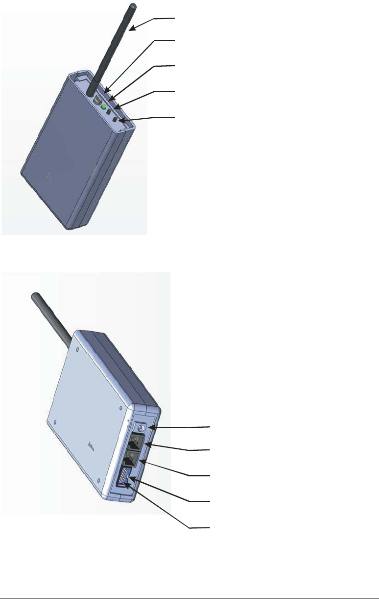
Identifying the parts
Antenna
Rotary Selector
Status LED
UP button
DOWN button
Power Input
RS485 Output
RS232/RS485 Input
Dry Contact Input
RS485 Termination
6
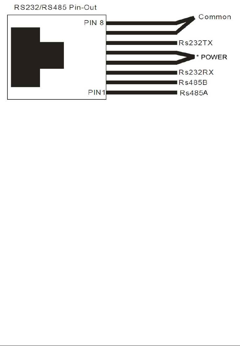
CONNECTOR PIN OUT
The Qmotion Qconnect has two RJ45 connectors and one 10 pin keyed male header.
The pin out description is as follows:
The RJ-45 connector is shown tab side down
*NOTE: optional. Power to the Qmotion Qconnect can be supplied on pins 4/5 and
7/8. By providing 5-9VDC positive on pins 4 and 5 and power ground on pins 7 and
8 the Qmotion Qconnect can powered by the CAT5 cable. The power supplied on
the RS485 input is daisy-chained on the RS485 output jack. In this way multiple
Qmotion Qconnect devices can be powered without the need for the connection of
the external power supply. The power supply used to provide power over CAT5
should be sized based on the number of Qmotion Qconnect devices connected on the
same run. Supply sizing for multiple bridges should allow for 1W at 5V for each
Qmotion Qconnect.
7
NOTE: The Qmotion Qconnect does not operate on “standard” power over Ethernet
schemes. Do not attempt to connect the Qmotion Qconnect to any Ethernet device.
Do not attempt to connect the Qmotion Qconnect to any POE (power over Ethernet)
device. Doing so, may damage the Qmotion Qconnect and/or the external Ethernet
or POE device. To power the Qmotion Qconnect over the RJ45 (RS485) interface,
you must follow the optional power instructions listed above.
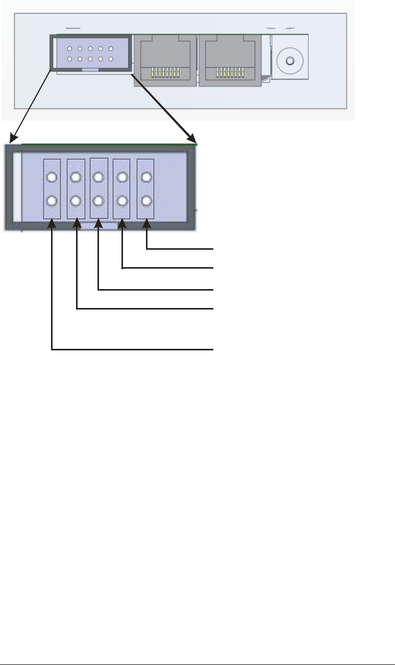
8
Bit1
bit2
bit3
bit4
termination
The Contact Interface consists of a 10pin 0.100” pitch male header that is keyed.
The Contact interface allows for sensing contact closure as commands for sending out
RF commands. Please refer to the Dry Contact Interface Section for details on
commands. The bit pairs indicated above (bit1 thru bit4) can be used individually or in
combinations to make 16 different dry contact events.
The outermost pair of pins (nearest the edge of the Qmotion Qconnect) is used to
enable the RS485 internal terminator. When daisy-chaining multiple Bridges together
using the RS485 interface, the first device (usually the initiator, PC interface, controller)
will have termination enabled, and only the last physical device in the daisy chain will
have termination enabled. For instance if three Qmotion Qconnect devices are daisy
chained together, only the last Bridge on the chain will have the terminator enabled.
A suitable mating connector such as WSW Components AWP10-7540-T-R or
equivalent may be used to interface the Qconnect Dry Contact Jack.

9
ASSEMBLY
To use your Qmotion Qconnect it is necessary to attach the supplied swivel RP-
SMA antenna. To attach the antenna, carefully align the antenna connector with
the antenna base and screw the antenna on in a clock wise direction. Do not over
tighten the antenna.
MOUNTING INSTRUCTIONS
The Qmotion Qconnect can be mounted to a wall or such by using the supplied
wall mount kit. The wall mount kit is designed to allow easy removal of the
Bridge.
Mount the wall mount kit adapter using suitable anchors for the wall material.
For best results, do not mount the Qmotion Qconnect on a metal or metal
containing wall. For best results, mount the bridge with the antenna pointing up
in the highest location possible near the group or bank of shades to be controlled.
LED ACTIVITY
The Qmotion Qconnect LED indicates the following:
While externally powered:
A solid red light indicates the bridge is in RS-232 mode.
A solid green light indicates the bridge is in RS-485 mode.
A solid amber light indicates the bridge is in Dry-Contact mode.
While battery powered:
Pushing the down button will cause the light to turn red while it is transmitting.
Pushing the up button will cause the light to turn green while it is transmitting.
Holding both buttons together will cause the light to turn amber indicating the
special function command is being transmitted.

10
ROTARY SELECTOR
The Qmotion Qconnect Rotary Selector is used for two functions.
When external power is absent from the Qmotion Qconnect, the Rotary selector is
used to pick one of 15 unique groups (or addresses) to lean to each Qmotion powered
shade. By selecting the group (address) with the Rotary selector and then pressing the
UP and DOWN buttons, it is possible to learn and control a Qmotion powered shade
manually with the Qmotion Qconnect. Please refer to the learning mode instructions
that come with your Qmotion shade to enter the proper learning modes.
When external power is present on the Qmotion Qconnect, the Rotary selector is used
to uniquely identify the Bridge on a daisy chain of Bridges connected with RS485
communication protocol. When using RS232 protocol, the Rotary selector is not
utilized and has no functionality.

11
THEORY OF OPERATION
The Qmotion Qconnect is a part of HomeRun Holdings Qmotion RF controls. The
Qmotion Qconnect is ideal for any residential or commercial setting where a serial
interface or dry contact interface is required to integrate with a third party automation
system. This is done through a RS485 or RS232 connection or a dry contact
connection with an external control system such as a PC or automation system.
Integration of the Qmotion Qconnect requires custom programming on the part of
the third party control system. The third party control system must implement the
serial protocol commands as defined later in this manual in order to send commands to
the Qmotion Qconnect. The Qmotion Qconnect receives the serial or dry contact
commands and translates them into Qmotion RF commands.
The Qmotion Qconnect has two modes of operation. A battery mode, and an always
powered mode (via supplied adapter, or optional serial power).
The battery mode of the Qmotion Qconnect is used to allow portability of the device
without needing cables. This mode is useful for setting up new shades and groupings
of shades. The Qmotion Qconnect has two push buttons, UP and DOWN. These
buttons are used for learning new shades and for testing shades locally. These buttons
are not functional when the Qmotion Qconnect is externally powered. The internal
battery of the Qmotion Qconnect should last several years if used as intended for the
training and testing of new shades. The serial interfaces and the dry contact interface
are not functional in battery mode.
The always powered mode (via supplied adapter, or optional serial power) is the
predominant way in which the Qmotion Qconnect will be used. In this mode the
serial interfaces and the dry contact interface are available. To use this mode it is
necessary to first setup your Qmotion shades to be trained/learned to the Qmotion
Qconnect (refer to battery mode above). The interface for normal operation must be
selected before attempting to control the Qmotion Qconnect with either of the serial
interfaces or the dry contact interface. The interface mode selection is described later
in this document.

12
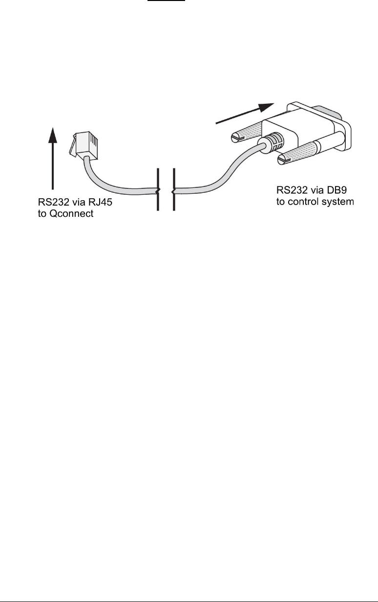
INTERFACE CABLE OPTIONS
The Qmotion Qconnect utilizes standard RJ-45 connector for both the RS232 and
RS485 interfaces. The pin-out of the signals for the RS232 connection and the RS485
connection is described in the RJ-45 pin out diagram earlier in this document. The
Qmotion Qconnect is not an Ethernet device, yet for daisy chaining multiple
Qconnect devices, standard CAT5 patch cables may be used. For connecting the
Qconnect to an external control system, a custom cable will usually be needed in order
to bring the control signals from the control system to the Qconnect. Please refer the
RJ-45 pin out diagram earlier in this document. There are two RJ-45 jacks on the
Qconnect. One is labeled “RS232/RS485 IN” and one labeled “RS485 OUT”.
The RS232/RS485 IN jack is used for making connection to a third party control
system. Either the RS232 or RS485 protocol can be used on this jack, but not both at
the same time. The RS485 OUT jack is used to daisy chain multiple Qconnect devices
together.
The DRY CONTACT header is used for making connection with external dry
contact sources such as Normally Open Relays or Normally Open Switches. A
temporary closure of any combination of bits 1 thru 4 (refer to diagram) is decoded by
the Qconnect as a request for the corresponding button code to be transmitted by the
Qconnect.

13
SELECTING THE INTERFACE (RS232, RS485, DRY CONTACT)
The Qconnect Bridge comes from the factory set for RS232 operation.
To change the mode to RS485, follow these steps:
a) Unplug the power supply
b) Hold the DOWN button
c) Still holding the DOWN button plug the power supply back in
To change the mode to Dry Contact, follow these steps:
d) Unplug the power supply
e) Hold the UP button
f) Still holding the UP button plug the power supply back in
To change the mode to RS232, follow these steps:
g) Unplug the power supply
h) Turn the rotary switch to ‘0’
i) Plug the power supply back in

14
RS232 OPERATION
The Qmotion Qconnect RS232 interface uses the following settings:
9600 BAUD, 8 Data Bits, 1 Stop Bit, No Parity
A communication packet consists of the following data:
15 channel ID’s.
Button code 0-F
LRC checksum
Each packet command to the bridge should include
a) SOF
b) Length
c) Type
d) Command ID
e) 0x00 (reserved)
f) Channel ID
g) Button Code
h) Checksum
Field Description
SOF Start Of Frame. Used for synchronization and is equal to 0x01
Length Number of bytes in the frame, exclusive SOF and Checksum. The
host application is responsible for entering the correct length field.
Type Used to distinguish between unsolicited calls and immediate
responses (not callback). The request (REQ) is equal to 0x00 and
response (RES) is equal to 0x01.
Reserved 0x00 .
Command ID
0x01: Request product info;
0x02: Factory Reset sets the channel address values back to factory values;
0x03: Request Address Information, returns the value of the requested
channel;
0x04: Assign Address Information, assigns a value to selected channel address;
0x05: Emit Button Code, sends a command to the shades
Channel ID Unique channel ID 0x01 – 0x0F for the selection of a particular
Channel (serial) to be transmitted via 433Mhz RF.

15
Button Code Unique button code ID 0x01 – 0x0F for the activation of a shade
function. (see appendix A for list of valid button codes)
Checksum LRC checksum used to check for frame integrity. Checksum
calculation includes the Length, Type, Command ID,0x00, Channel ID, Button
Code fields. The Checksum is a XOR checksum with an initial checksum value of
0xFF.

16
RS485 OPERATION
The Qmotion Qconnect RS485 interface uses the following settings:
9600 BAUD, 8 Data Bits, 1 Stop Bit, No Parity
A communication packet consists of the following data:
15 channel ID’s.
15 interface ID’s
Button code 0-F
LRC checksum
The baud rate for RS232 and RS485 operation will be, 4800 baud, 8 data bits, 1
stop bit, No parity
Each packet command to the bridge should include
a) SOF
b) Length
c) Type
d) Command ID
e) Interface ID
f) Channel ID
g) Button Code
h) Checksum
Field Description
SOF Start Of Frame. Used for synchronization and is equal to 0x01
Length Number of bytes in the frame, exclusive SOF and Checksum. The
host application is responsible for entering the correct length field.
Type Used to distinguish between unsolicited calls and immediate
responses (not callback). The request (REQ) is equal to 0x00 and
response (RES) is equal to 0x01.
Command ID
0x01: Request product info;
0x02: Factory Reset sets the channel address values back to factory values;
0x03: Request Address Information, returns the value of the requested
channel;
0x04: Assign Address Information, assigns a value to selected channel address;
0x05: Emit Button Code, sends a command to the shades

17
Interface ID Unique interface ID 0x01 – 0x0F for the selection of particular
Addressed bridge device on RS485 chain.
Channel ID Unique channel ID 0x01 – 0x0F for the selection of a particular
Channel (serial) to be transmitted via 433Mhz RF.
Button Code Unique button code ID 0x01 – 0x0F for the activation of a shade
function. (see appendix A for list of valid button codes)
Checksum LRC checksum used to check for frame integrity. Checksum
calculation includes the Length, Type, Command ID, Interface ID, Channel ID,
Button Code fields. The Checksum is a XOR checksum with an initial checksum
value of 0xFF.

18
DRY CONTACT OPERATION
The dry contact interface allows for external contact closures such as those from relay
contacts to initiate RF commands.
The Qmotion Qconnect has four (4) pairs of male header pins which can be used to
wire in contact control signals. The dry contact interface provides it’s own source
power for making contact closure determination. A low impedance path established
by an external switch or relay can be sensed by the Bridge and will initiate an RF
command equivalent to the binary value of the contact input. For instance a contact
closure of the input pins associated with “bit1” will cause binary button code 0001 (1
Decimal, 0x01 hex) to be transmitted. Contact closure of the input pins “bit3” and
“bit1” will cause binary button code 0101 (5 decimal, 0x05 hex) to be transmitted.
Please refer to APPENDIX A for button code values.

19
APPENDIX - A – button code list
FUNCTION BUTTON CODE
(DECIMAL)
BUTTON CODE
(HEX)
BUTTON_STOP 0 0x00
BUTTON_UP 1 0x01
BUTTON_DOWN 2 0x02
BUTTON_FUNCTION1 3 0x03
BUTTON_SETPOINTA 4 0x04
BUTTON_FUNCTION2 5 0x05
BUTTON_PRESET1 6 0x06
BUTTON_PRESET2 7 0x07
BUTTON_SETPOINTB 8 0x08
BUTTON_PRESET3 9 0x09
BUTTON_PRESET4 10 0x0A
BUTTON_PRESET5 11 0x0B
BUTTON_SETPOINTC 12 0x0C
BUTTON_PRESET6 13 0x0D
BUTTON_PRESET7 14 0x0E
BUTTON_RESERVED 15 0x0F

20
Revisions
Rev. 0.1 B. Garcia 10/5/2011 initial release
Rev. 0.2 B. Garcia 10/6/2011 corrections/additions
Rev. 0.3 B. Garcia 10/6/2011 additions
Rev. 0.4 J. Watts 10/6/2011 additions
Rev. 0.5 J. Watts 10/6/2011 additions