The Watt Stopper MRDS10 Wireless Touchscreen Controller User Manual USERS MANUAL
The Watt Stopper, Inc. Wireless Touchscreen Controller USERS MANUAL
Contents
- 1. OPERATING MANUAL
- 2. USERS MANUAL
USERS MANUAL
Status LED Indicator
The LED can display one of three co lo rs: green, ye l l ow (amber, a
combination of red and green), or red. The co lor can be co n stant, or
can flash at one of three ra tes to further distinguish re p o r te d
conditions. To determine the flash ra te, count the number of fla s h e s
in 5 seco n d s :
5 fla s h e s. . . . . . . . . . . . . . . . . . . . . . . . . . . . . . . . . . . . . . . . . . . . . . . . . . . . . . . . . . . . . . . . . . . . . . . . . . . . . . . . .1 Hz
10 fla s h e s. . . . . . . . . . . . . . . . . . . . . . . . . . . . . . . . . . . . . . . . . . . . . . . . . . . . . . . . . . . . . . . . . . . . . . . . . . . . . . .2 Hz
15 fla s h e s. . . . . . . . . . . . . . . . . . . . . . . . . . . . . . . . . . . . . . . . . . . . . . . . . . . . . . . . . . . . . . . . . . . . . . . . . . . . . . .3 Hz
MRDS10 LED Indications are as fo l l ow s :
C o l o r B e h a v i o r M e a n i n g
n o n e O f f D e v i c e is not powe r ed or is in “sle e p ”
m o d e .
G r e e n On, not fla s h i n g D e v i c e is powe red, has a house ID,
o p e rating normally.
G r e e n Flashing @ 2 Hz During binding, dev i c e is excluded, but
can be added.
Ye l l ow On, not fla s h i n g D ev i c e does not have a house ID.
Ye l l ow Flashing @ 2 Hz D ev i c e is part of a binding pro c e s s, either
G r oup or Room. Binding was sta r ted by
some other dev i ce and must be sto p p e d
on the other dev i ce .
Ye l l ow Flashing @ 3 Hz D ev i c e is the master of a binding
p r o ce s s. Binding was sta r ted on this
d ev i ce and must stop on this dev i ce .
R e d Flashing @ 2 Hz D e v i c e has enco u n te red an erro r. An
i n valid command was atte m p te d .
Caution: Battery Vo l tage is Low ~ 10s
every 1-2 minute s
R e d Flashing 3 Hz Shutting down To u c h s c r een due to low
b a t t ery co n d i t i o n
APPLICATION ASSISTANCE
The wire le s s network may co n tain a variety of wire l e s s dev i c e s .
I n structions for installation, binding operations, and use are
included with the re l evant wire l e s s dev i c es. Application support
i n f ormation and installation guides for Watt Sto p p e r / L e g ra n d
w i r e le s s network dev i c es are ava i l a b le at www. w a t t s to p p e r. c o m .
SPECIFICATIONS
UL and cUL Liste d
Power Supply / C h a r ger (MRDP10)
Input Vo l ta g e . . . . . . . . . . . . . . . . . . . . . . . . . . . . . . . . . . . . . . . . . . . . . .1 2 0 VAC, 0.15A, 60 Hz
Output Vo l t a g e . . . . . . . . . . . . . . . . . . . . . . . . . . . . . . . . . . . . . . . . . . . . . . . . . . . . . . . . 8VDC, 600mA
To u c h s c r een (MRDS10)
Input (charging) Vo l t a g e . . . . . . . . . . . . . . . . . . . . . . . . . . . . . . . . . . . . . . . . .8VDC, 600 mA
DESCRIPTION
The MRDS10 To u c h s c r een is a Top Dog™ wire le s s network House,
Room and Group level co n t r o l le r. It has a 2-co lor LCD touch panel
d i s p l a y.
The To u c h s c r een can be opera ted with power supplied by the
MRDP10 wall-mount charger, the optional MRDC10 ta b le - to p
c h a rger, or it can be te m p o ra r i ly re m o ved from the power supply to
be used as a porta b le hand-held dev i c e .
Top Dog™ Wireless Communication
Watt Stopper wire l e ss dev i c es use radio signals to co m m u n i ca te with
each other to co n t rol lighting and other types of electric loads in
s e le c ted areas. These wire l e ss dev i ces use the 900MHz band fo r
high-speed co n t rol co m m u n i cation. Using the Watt Sto p p e r ’s ow n
“ f r e q u e n c y - a g i le” Top Dog™ te c h n o logy, these wire l e ss dev i ces avo i d
i n t e r fe r e n ce with other 900MHz dev i c es, such as co rd l e s s phones
and baby monito rs .
OPERATION
The MRDS10 To u c h s c r e e n is a house level scene co n t r o l le r.
The MRDP10 is included with the MRDS10 package. It is a wall-
m o u n t ed power supply and battery charger for the To u c h s c r een. The
To u c h s c r een can be used while attached to the MRDP10, or it can be
te m p o ra r i l y re m oved from the MRDP10 and used as a porta b l e
handheld dev i ce. The To u c h s c r een should be returned to a MRDP10
or MRDC10 power supply to re c h a rge its batte r i e s .
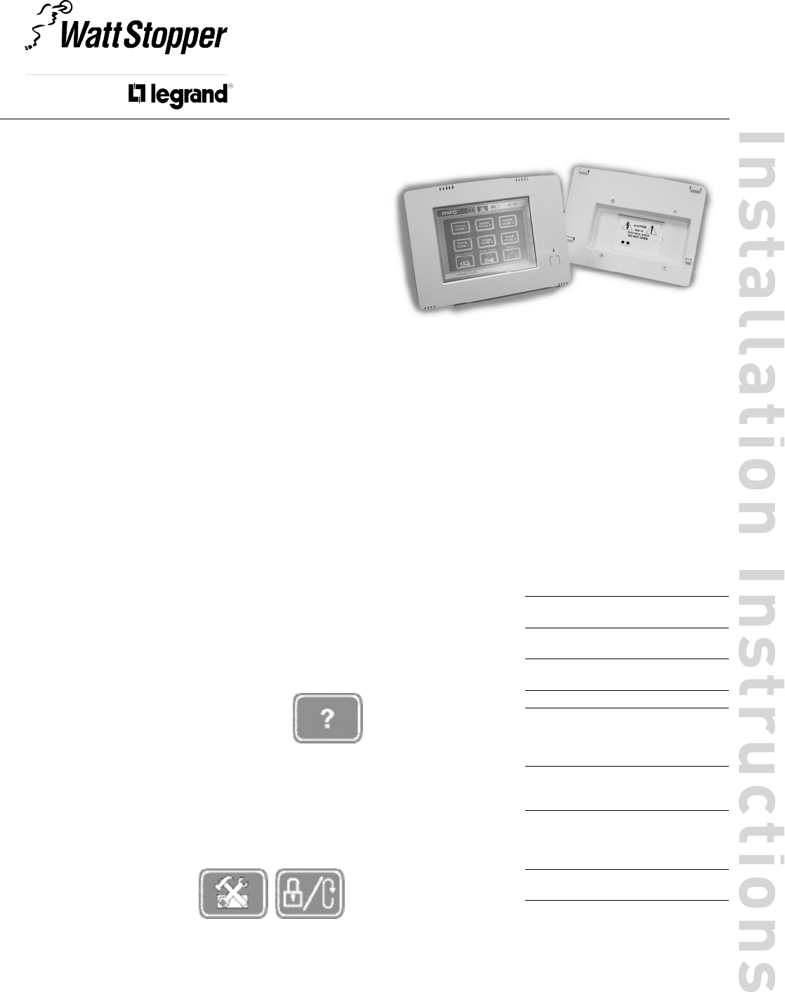
Human Interface
The primary human inte r fa ce on the MRDS10 is the To u c h s c re e n .
The menus and co n t rol functions are acce s sed by
touching the labels and icons on the screen. The
To u c h s c r een has a help system built into each page.
To acce ss help and information about a particular
page, pre s s the question mark button at the top of any
p a g e .
The MRDS10 also uses a multi-co lor LED (gre e n / a m b e r / red) to
i n d i c a te dev i ce status. Dire c t ly below the LED there is a single push-
b u t t on. Momenta r i ly pre s s this button to wake up the dev i c e when in
p ower save mode. This button also acts as a software reset (re b o o t )
function when held for a period of 10 seconds. When this is done the
fa c tory default co n t ra st and brightness settings are re s to red. No
other setup information is alte r ed.
To reset the unit to a fa c to r y
d e f ault sta te, the user must use
the To u c h s c reen to go into the
setup menu and perform this
function in the Lock/Reset page .
Power Fail Memory
A f ter a power fa i l u re, all wire l e ss dev i c es auto m a t i c a l l y return to the
sta te that they we re in immediate ly prior to lo s s of powe r. All
co n fi g u r ation and scene co n t rol information is pre s e r ved.
M R D S 1 0
W i re l e s s To u c h s c r een Contro l ler with
wall-mount power supply & charg e r
WALL-MOUNT POWER SUPPLY INSTALLATION
The MRDP10 can be insta l led in a user occupied space within radio ra n g e
of the wire l e s s network dev i ces. It must be insta l led in acco rd a n ce with
national and lo cal ele c t r i cal codes by qualified pers o n n e l .
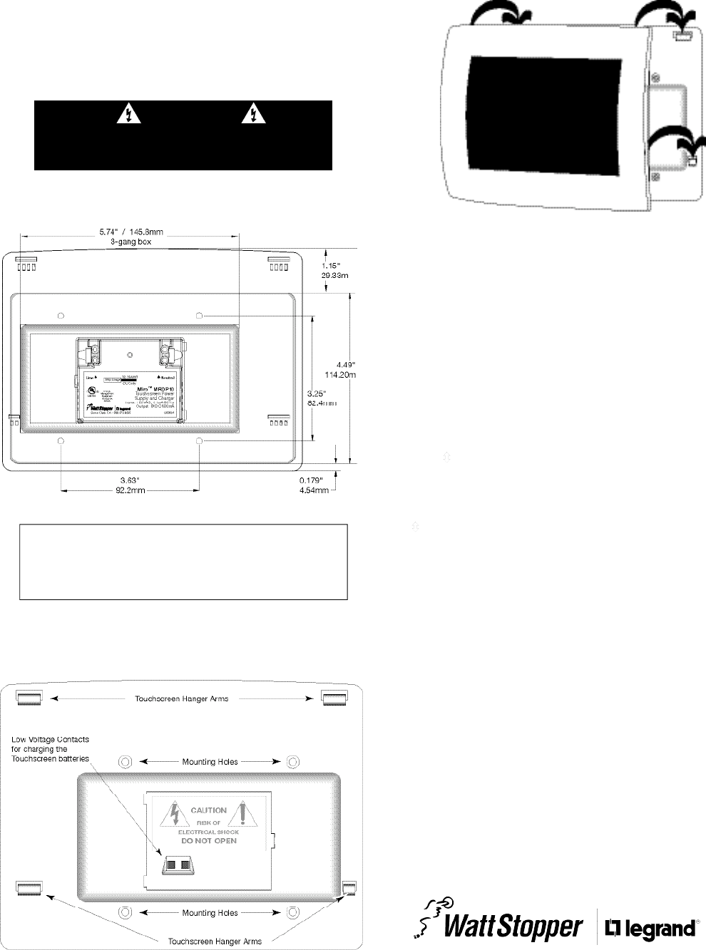
The MRDP10 housing is designed for installation in a 3-gang ele c t r i c al box
using four mounting holes on the unit. Radio co m m u n i cation cannot be
g u a ra n teed if the unit is mounted in a metallic ele c t r i cal enclo s u re.
1 . C o m p le te the physical installation and binding of all other wire le s s
d ev i c es in the network.
2 . Shut off the circuit bre a k e r.
3 . I n s tall a 3-gang (minimum) ele c t r i cal wall box in a lo cation co n v e n i e n t
to the system user.
Back of MRDP10
4 . W i re the MRDP10 to the 120VAC supply circuit using the NEUTRAL and
LINE terminals as indica ted on the back of the MRDP10.
5 . S e c u re the MRDP10 to the ele c t r i c al wall box using the 4 mounting hole
s c rew lo c a t i o n s .
Front of MRDP10
Do not lo c a te the MRDP10 close to any dev i ce that may ca u s e
i n t e r fe re n c e or behind large metal objects that can block ra d i o
re ception. Avoid flu o r e s c ent light fix t u r es, TV sets, co m p u te rs ,
re f r i g e ra to rs, microw a ve ovens, range hoods, safes, etc .
CAUTION
TURN THE POWER OFF AT THE CIRCUIT
BREAKER BEFORE INSTALLING THE MRDP10.
2800 De La Cruz Bouleva rd, Santa Clara, CA 95050
Te c h n i cal Support: 800.879.8585 • 972.578.1699
w w w. w a t t s to p p e r. c om 05988r1 09/2005
FCC NOTICE
This equipment has been te s ted and found to co m p ly with the limits
for a Class B digital dev i c e, pursuant to part 15 of the FCC Rule s .
These limits are designed to provide re a s o n a b le pro tection against
harmful inte r fe re n c e in a residential installation. This equipment
g e n e ra tes, uses and can ra d i a te radio frequency energy and, if not
i n sta l l ed and used in acco rd a n c e with the instructions, may ca u s e
harmful inte r fe re n c e to radio co m m u n i c ations. However, there is no
g u a ra n tee that inte r fe re n c e will not occur in a particular insta l l a t i o n .
If this equipment does cause harmful inte r fe re n ce to radio or
te levision re c eption, which can be determined by turning the
equipment off and on, the user is enco u r aged to try to co r rect the
i n t e r fe re n c e by one or more of the fo l lowing measure s :
• Reorient or re lo ca t e the re c eiving ante n n a .
•I n c rease the separation between the equipment and re c e i ve r.
• Connect the equipment into an outlet on a circuit diffe r ent fro m
that to which the re ce i ver is co n n e c te d .
• Consult the dealer or an ex p e r i e n ced radio/TV technician for help.
Caution: Any changes or modifications to this dev i ce not ex p l i c i t ly
a p p r oved by Watt Sto p p e r / L e g rand could void your authority to
o p e ra te this equipment.
6 . Hang the To u c h s c reen from the To u c h s c r een Hanger Arms on the fro n t
of the MRDP10. Once yo u ’ re sure that the hanger arms are in all 4 slo t s
of the To u c h s c reen, lightly push dow n w a rd on the To u c h s c reen frame to
e n s u r e that the Low Vo l t age Contacts make connection to the
To u c h s c r een battery co n t a c t s .
7 . The status LED lights ye l l ow, indicating that the unit is ready fo r
co n fi g u r ation. See SET HOUSE ID in this manual.
SET HOUSE ID
All Watt Stopper Top Dog wire l e ss dev i c es insta l led in the same syste m
m u st acquire the same unique House ID befo re use. This pro ce s s is
k n own as house binding. Each wire l e ss dev i ce is bound to all other
w i r e le s s dev i c es in the house. If you are not familiar with the binding
p r o c e ss for the dev i c es in your installation, please rev i ew the Insta l l a t i o n
Guide, or individual installation instructions provided with the dev i ce s .
The House ID binding gives the To u c h s c r een the same House ID as the
re st of the wire le s s network.
1 . M a k e sure all dev i ces are insta l l ed and energized and all group, house,
and room bindings are co m p le t e. Make sure that every other wire le s s
d ev i ce LED is green and the MRDS10 is ye l low (amber).
2 . P re s s on any p r ev i o u s ly bound d ev i ce until its LED flashes amber
(about 2 seco n d s ) .
3 . Verify that the LED on the MRDS10 starts flashing green. This sets the
House ID to match the other dev i c es in the house.
4 . Return to the same prev i o u s ly bound d ev i ce used in step 2 and pre s s
until its LED changes to solid green (about 2 seconds). All dev i ce
LEDs including the MRDS10 should now be solid gre e n .