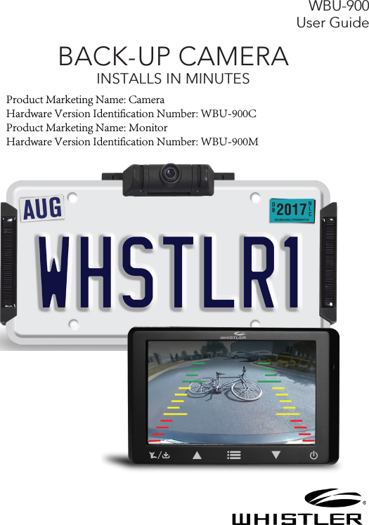
The Whistler Group BU01M BACK-UP CAMERA(Monitor) User Manual

The Whistler Group BACK-UP CAMERA(Monitor)

User Manual

WBU-900 User GuideBACK-UP CAMERA INSTALLS IN MINUTESProduct Marketing Name: CameraHardware Version Identification Number: WBU-900CProduct Marketing Name: MonitorHardware Version Identification Number: WBU-900M
2WelcomeThank you for choosing a Whistler product. We are dedicated to providing products that represent both quality and value. Please read the User Guide carefully before using this product. If you have additional questions, please visit the FAQ page on our website at www.whistlergroup.comor call Toll Free (800) 531-0004 / Tel (479) 273-6012, 8am to 5pm CT, Monday through Friday to speak to a Customer Service Representative.The Back-Up Camera displays images behind the vehicle, and can be used when backing up or anytime you need to view behind the vehicle even when the vehicle is in park.INTRODUCTION
3Features• 4.3" Color monitor with backlit capacitive touch buttons• Weatherproof camera with 110° viewing angle• Solar Cells for extended battery life• Modular design can be placed above or below your licenseplate• Adjustable vertical camera tilt angle• Suction Cup with adjustable arm for windshield ordashboard mounting• Dash Disk provides smooth surface for suction cup to bedash mounted• Back-up assist guidelines• Image Rotation / MirroringFEATURES
4FEATURES1. Monitor2. Camera3. Solar cell4. Solar cell5. Suction cup mount6. Dash disk7. Tie wraps8. License back-plate9. 4 Long screws (Domestic)10. 4 Long screws (Import)11. 2 Short Machine screws12. 2 Machine nuts13. 2 Cushions14. 4 Adhesive disks15. 4 Adhesive strips16. 4 Cable tie mount17. 4 Spacers18. Power cord19. USB cord12 3 45 687910 1112 13 14 15 16171819
5CHARGING CAMERA ASSEMBLYThe Camera under normal use, will maintain a charge with exposure to sunlight. A battery status indicator is provided on the monitor when the camera is in use. If you’re storing your vehicle in a garage for more than a one month, or are otherwise not exposing the Camera to sunlight on a regular basis, you may need to recharge it via the Micro USB charge port.To recharge the Camera:1. If attached to vehicle, please remove.2. Connect the supplied USB cord to the Micro USB port ofthe camera assembly.3. Plug the USB cable into any standard USB charger with anoutput rating of 500ma or higher.4. Charge 4 to 5 hours if the battery was completely depleted5. Once charged, Re-install the Camera assembly to yourvehicle.NOTE: It is recommended to fully charge your Camera before installing on the vehicle.Tips to optimize the solar charge:1. Be sure that the solar panels are are clean, and dust/dirt-free.2. Park in a location where the sun is or will be shining directlyon the solar panels for at least 1-2 hours a day.3. One hour of good sunlight daily offsets the daily powerconsumption of the Camera.
6NoticeSome states or local governments may have regulations or laws that restrict the use of anything that might impair the clear view of a license plate. Check local laws for complianceThese instructions are only meant as a general guide due to the number of different makes and models of vehicles.1. Remove license plate from vehicle and place on top ofthe supplied license backplate.2. Insert 2 short machine screws into 2 of the mounting holesand finger tighten 2 machine nuts onto them in order tohold the plates together for steps 3 thru 6.3. Apply an adhesive strip to each of the solar panel basesand two adhesive strips to the camera base as shownbelow.4. Peel the backing from the adhesive strips on the solarpanel bases and carefully slide onto each side (left andright) of the plate assembly being careful not to makecontact with the adhesive until the base is fully inserted.ASSEMBLY / INSTALLATION
7ASSEMBLY / INSTALLATION5. With the solar mounts centrally positioned, apply pressureto set the adhesive tape.6. Peel the backing from the adhesive strips on the camerabase and carefully slide onto the long edge of the licenseplate assembly positioned centrally between the licenseplate mounting holes.7. Remove the 2 short machine screws and nuts used earlierand set aside.8. Apply the 4 adhesive disks to the flat side on each of the4 spacers.9. Peel the backing from the adhesive disks and apply onespacer over each license plate mounting holes.10. Apply pressure to set the adhesive tape.
811. Reinsert the 2 short machine screws into the 2 holes ifthese are not used to attach to your vehicle, insert themachine nuts, then tighten.12. If needed, 2 cushions are provided to protect yourvehicle. Attach to the back of the spacers containing themachine nuts.13. Connect the solar panel connectors to the matingconnectors from the main camera housing and placethe tie wrap adhesive pads as shown. Use 2 tie wraps toneatly hold the cables in place and cut the excess lengthof the tie wrap if desired.14. Attach the assembly to the vehicle with the appropriatelicense plate mounting screws for your vehicle type.NOTE: Domestic and Import license plate screws are included and should be compatible with the vast majority of vehicles. Should your vehicle require a special diameter or thread, please consult your dealer. ASSEMBLY / INSTALLATION
9ASSEMBLY / INSTALLATIONThe camera angle should be adjusted to provide an optimal view of objects behind the vehicle. 15. Adjust the camera angle as required:•To adjust the camera angle, tilt the camera to the correctangle.•The camera should be adjusted to a horizontal positionrelative to the ground, so as to provide optimal view ofobjects behind the vehicle.•Carefully tighten the 2 screws ½ turn to prevent thecamera angle from moving during vibrations from driving.16. Find a mounting surface inside the vehicle for the monitorwhere it can be easily seen, and does not obstruct yourvision when driving.NOTE: To maximize the effectiveness of the suction mount, the mounting location surface temperature should be between 50° and 100°F. Avoid application below 50°F.NOTE: Before permanently mounting the monitor, test the reception of the camera signal in several selected locations within easy reach as one may have better reception than another. If mounting to the dashboard, the dash disk must be used to ensure a smooth surface for the   suction cup to attach.
10ASSEMBLY / INSTALLATION17. Clean and dry the mounting surface before applyingsuction cup or dash disk.18. Press the suction mount against the mounting surface andpush the suction lock lever down. Make sure it is attachedsecurely.19. Slide the monitor onto the monitor arm. The monitorangle can be adjusted by loosening the monitor angleadjustment knobs, tilting the monitor, then tightening theknobs.20. Plug the monitor cigarette lighter/accessory socket powercord into a 12-volt DC power port.
11Testing the System1. With power applied to the monitor, the button backlightwill illuminate to indicate the monitor is ON and inStandby mode.2. The Blue LED will blink briefly to indicate that it isattempting to communicate with the camera. Whenconnected to the camera, the blue LED will turn solid.It may take a moment for the camera to begin sendingthe video information, allow time for the image to bedisplayed.3. The Image is set to time out in 30 seconds however ifyou wish to shut the image off manually, touch the multi-function button anytime that video is present to stopthe video transmission and put the camera back into itspower conserve mode.4. If 12-volt DC power port is live all the time, to shut thebutton backlight off, touch and hold the   button for 3seconds. The monitor retains this setting and must beturned back on in order to receive video. This can bedone easily with a touch of the   button. Standby isconfirmed when the button backlight remains ON.NOTE: If Monitor has been shut off with   button, removing the power source and reapplying will not turn your monitor on as the OFF function is stored in Memory and the unit must be turned ON with a touch of the   button. NOTE: If using a switched 12-volt DC Power port, it is not necessary to power off the monitor unless you do not wish to receive an image automatically with the starting of your vehicle.OPERATION
125. If your 12-volt DC power port is switched on with yourignition, the unit will automatically request an imagefrom the backup camera each time you start your vehicle.When the vehicle is shut off, power is removed from themonitor and the button backlight will shut off.6. Route and secure all wires as needed.OPERATION
13FUNCTIONFunctions of the Touch Buttons (left to right)         : Touch to enable or cancel the transmitter; Touch for 3 seconds to turn on/off the backup assist lines. Touch to select a corresponding function. : Touch to move to or adjust a corresponding function : Touch to enable/cancel the menu.: Touch to move to or adjust a corresponding function. : Touch briefly to turn on, Touch and hold for 3 seconds to turn on/off.Adjusting Monitor Settings:1. Touch the  button to bring up the   Options.2. Touch  or  arrow to scroll through the different functions.3. Touch the  button to enter the function.4. Touch the   button to increase or the   button todecrease settings.5. To change the view on the screen, scroll to Rotation thentouch the   button to select 1 of 4 image rotations.  (It is best to have a video image displayed when making this selection)6. To exit, touch the  button or wait for the 15 second timer to exit automatically.7. To turn the guidelines On or Off, with an image on thedisplay, touch the   button for 3 seconds then release.
14MONITOR SETTINGSMenu Operations: Enter the main Menu Interface   and 4 options are available including Image Parameters, Image Rotation, Code Pairing and Software Information. Press   and   to select corresponding option, and then touch the   button to enter the option:Image Parameters (Brightness, Contrast, Color) Setting Interface are shown above:
15MONITOR SETTINGSBrightness/Contrast/Color Settings are similar. Take Brightness as an example, when Brightness is chosen, press   or   on the interface to adjust the brightness as shown above:Select “Image Rotation”, and then touch the   button to rotate or mirror the image. (It is best to have a video image displayed when making this selection).Select “Code Pairing”, and touch the   button to enter Code Pairing Mode; then, power on the camera by connecting the solar cell cables to finish the Code Pairing.NOTE: When it’s connected with the receiver for the first time, the Code Pairing operation is required. Please select the option “Code Pairing” from the receiver, and it will reveal “PAIR ICON”. Then, please connect the transmitter with solar panels, and the transmitter will enter Code Pairing mode. After the Code Pairing operation, “OK” will appear on PAIR ICON of the receiver to indicate the successful pairing. In this case, the receiver can receive corresponding image information.Select “Software Information”, and touch the   button to display the software version information.
16INFORMATIONBattery Icon is on the top left corner of the monitor, and indicates the relative capacity of the built-in lithium battery when a video image is present.Signal strength of the received image is on the top right corner of the monitor when a video image is present.The Camera and Video Transmitter: The Camera / Video transmitter is equipped with the built-in rechargeable lithium battery and is connected with two solar panels that trickle charge the built-in lithium battery when sunlight is available to minimize or eliminate the need for needing to manually recharge during the year. A USB charging port is provided to initially charge the battery prior to mounting on your vehicle as well as to recharge if needed. Your rechargeable battery when fully charged will last for several months of average use with NO SUNLIGHT (avg use is defined as 4~6 times per day). With the addition of sunlight, the solar cells will charge your battery thereby extending the cameras ability to provided usage day after day and month after month without requiring you to recharge it manually.When the Monitor is turned ON, or when the button backlight is ON and the   button is touched, a wake-up signal is sent to the camera and upon seeing this signal, it will awake the camera and transmitter in order to send an image to the monitor for 30 seconds, and then enter the Sleep Mode again.
17TROUBLESHOOTINGIf the monitor does not turn on when power is applied:•Check to make sure the power source is active (if yourcigarette lighter is switched with vehicle ignition, your monitor will only work when the vehicle is running or the key in the ON position).•Check to make sure the fuse and power cord are inworking order•With power applied to the monitor, touch the powerbutton.If the monitor does not display images within a few seconds of pressing the   button:•The battery in the camera may be depleted and requirerecharging.•The signal may be weak due to positioning of the cameraand monitor (try reposition the monitor to another location).If the video image is poor:•Check that the camera lens is clean from road grime,snow, or ice.If the image appears shake when the vehicle is moving: •Check the camera mounting screws to the vehicle andretighten if needed.•Check the camera tilt adjustment and retighten thescrews if loose. If the video image does not last 30 seconds:•Recharge the battery in the camera.
18DISCLAIMERThe Whistler Digital Wireless Backup Camera is intended to assist responsible drivers, but it does not relieve a driver from full responsibility for the operation of the vehicle. It is the driver’s sole responsibility to avoid contact with any objects, animals, or persons. By mounting and/or using the Whistler Digital Wireless Backup Camera, you agree that you are solely responsible for the operation of your vehicle and that The Whistler Group is not responsible for any property damage, personal injury, or loss of life that may result from the operation of your vehicle.Notice to Drivers in California and Minnesota:State law prohibits drivers in California and Minnesota from using suction mounts on their windshields while operating motor vehicles. Other dashboard mounting options should be used. (See California Vehicle Code Section 26708(a); Minnesota Statutes 2005, Section 169.71).Notice:Some states or local governments may have regulations or laws that restrict the use of anything that might impair the clear view of a license plate. Check local laws for compliance.
19CleaningDo not clean or wipe the Back-Up Camera with solvents or chemical materials. If necessary, remove dirt or stains using a soft cloth dampened with a mild detergent solution.Fuse Replacement1. Turn the cap on the tip of the power plug counterclockwise(no tools needed).2. Remove the cap, center pin and fuse.3. Replace the fuse with a new 1-amp fuse.4. Replace the center pin and cap. Turn the cap clockwise.DisposalThe Back-Up Camera is designed to provide years of service. The Back-Up Camera should be recycled or safely disposed of at a local recycling center. Examples of places that will accept items like this are: county or municipal recycling drop-off centers or scrap metal dealers.CARE AND MAINTENANCE
20FCC INFORMATIONIMPORTANT: FCC (Federal Communications Commission) requirements state that changes or modifications not expressly approved by Whistler could void the user’s authority to operate the equipment.THIS DEVICE COMPLIES WITH PART 15 OF THE FCC RULES. OPERATION IS SUBJECT TO THE FOLLOWING TWO CONDITIONS: (1) THIS DEVICE MAY NOT CAUSE HARMFUL INTERFERENCE, AND (2) THIS DEVICE MUST ACCEPT ANY INTERFERENCE RECEIVED, INCLUDING INTERFERENCE THAT MAY CAUSE UNDESIRED OPERATION.Note: This equipment has been tested and found to comply with the limits for a Class B digital device, pursuant to part 15 of the FCC Rules. These limits are designed to provide reasonable protection against harmful interference in a residential installation. This equipment generates, uses and can radiate radio frequency energy and, if not installed and used in accordance with the instructions, may cause harmful interference to radio communications. However, there is no guarantee that interference will not occur in a particular installation. If this equipment does cause harmful interference to radio or television reception, which can be determined by turning the equipment off and on, the user is encouraged to try to correct the interference by one or more of the following measures:—Reorient or relocate the receiving antenna.—Increase the separation between the equipment and receiver.—Connect the equipment into an outlet on a circuit different from that to which the receiver is connected.—Consult the dealer or an experienced radio/TV technician for help.NOTE:   THE GRANTEE IS NOT RESPONSIBLE FOR ANY CHANGES OR MODIFICATIONS NOT EXPRESSLY APPROVED BY THE PARTY RESPONSIBLE FOR COMPLIANCE. SUCH MODIFICATIONS COULD VOID THE USER’S AUTHORITY TO OPERATE THE EQUIPMENT. RF warning statement:The device has been evaluated to meet general RF exposure requirement. To maintain compliance with FCC's RF exposure guidelines, this equipment should be installed and operated with a minimum distance of 20cm between the radiator and your body.
21SPECIFICATIONSCAMERAOperational Current (when transmitting): <220mAPixels: 640 x 480View Angle: 110° Image Sensor: 1/4“ CMOS VGAImage Quality: Max 25 fps.TRANSMITTERFrequency: 2409.75 ~ 2472.75MHzRF transmission distance: >328 ft. (>100 m)Operation/storage temperature: 14° to 122°F (-10° to 50°C)MONITORLCD display screen size: 4.3 in.Power cord fuse: 1AOperational Current: <250mAEffective Pixels: 480 x 272Working temperature: -10 to +50C
22WARRANTY INFORMATIONConsumer WarrantyThis Whistler product is warranted to the original purchaser for a period of one (1) year from the date of original purchase against all defects in materials and workmanship, when purchased from an authorized Whistler retailer. This limited warranty is void if the unit is abused, misused, modified, installed improperly, or if the housing and/or serial numbers have been removed. There are no express warranties covering this product other than those set forth in this warranty. All express or implied warranties for this product are limited to one (1) year. Whistler is not liable for damages arising from the use, misuse, or operation of this product including but not limited to loss of time, inconvenience, loss of use of your product or property damage caused by your product or its failure to work, or any other incidental or consequential damages including personal injury.DO NOT RETURN ITEM TO STORE WHERE PURCHASED.For warranty information, contact Whistler Customer Service at Toll Free (800)531-0004 / Tel (479)273-6012Representatives are available to answer your questionsMonday - Friday from 8:00 a.m. to 5:00 p.m. CT
23WARRANTY INFORMATIONService Under WarrantyDuring the warranty period, defective units will be repaired or replaced (with the same or a comparable model), at Whistler’s option, without charge to the purchaser when returned prepaid, with dated proof of purchase to the address below. Units returned without dated proof of purchase will be considered out of warranty and therefore are not covered by the described Limited Warranty. (Refer to Service Out-of-Warranty section.)Due to the specialized equipment necessary for testing Whistler products, there are no authorized service centers other than Whistler. When returning a unit for service under warranty, please follow these instructions:1.  Ship the unit in the original carton or in a suitable sturdyequivalent, fully insured, with return receipt requested to:Whistler Repair Dept.1412 South 1st St.Rogers, AR. 72756Please allow 3 weeks turnaround time.
24WARRANTY INFORMATIONIMPORTANT: Whistler will not assume responsibility for loss or damage incurred in shipping. Therefore, please ship your unit insured with return receipt requested. CODs will not be accepted!2.  Include with your unit the following information, clearlyprinted:•Your name and physical street address for shipping (noPO Boxes),  a daytime telephone number, and an emailaddress (if applicable).•A detailed description of the problem (e.g.,“device willnot  power ON”).•A copy of your dated proof of purchase or bill of sale.3.  Be certain your unit is returned with its serial number.Units without serial numbers are not covered underwarranty.IMPORTANT: To validate that your unit is within the warranty period, make sure you keep a copy of your dated proof of purchase. For warranty verification purposes, a copy of your dated store receipt must accompany any Whistler product sent in for warranty work.
25Service Out-Of-WarrantyUnits will be repaired at “out-of-warranty” service rates when:•The unit’s original warranty has expired.•A dated proof of purchase is not supplied.•The unit has been returned without its serial number.•The unit has been misused, abused, modified, installedimproperly, or had its housing removed.The minimum out-of-warranty service fee for your Whistler product is $65.00. If you require out of warranty service, please return your unit as outlined in the section “Service Under Warranty” along with a cashier’s check or money order in the amount of $65.00. Payment may also be made by MasterCard, VISA or American Express. Personal checks are not accepted.In the event repairs cannot be covered by the minimum service fee, you will be contacted by a Whistler technical service specialist who will outline options available to you.WARRANTY INFORMATION
26IMPORTANT: When returning your unit for service, be certain to include a daytime telephone number and an email address (if applicable).Customer ServiceIf you have questions concerning the operation of your Whistler product, or require service during or after the warranty period, please call Customer Service at Toll Free (800)531-0004 Tel (479)273-6012Representatives are available to answer your questions Monday - Friday from 8:00 a.m. to 5:00 p.m. (CT) or visit the FAQs at www.whistlergroup.comWARRANTY INFORMATION
27IC Warning:This device complies with Industry Canada licence-exempt RSS standard(s). Operation is subject to the following two conditions: (1) this device may not cause interference, and (2) this device must accept any interference, including interference that may cause undesired operation of the device.Le présent appareil est conforme aux CNR d'Industrie Canada applicables aux appareils radio exempts de licence. L'exploitation est autorisée aux deux conditions suivantes : (1) l'appareil ne doit pas produire de brouillage, et (2) l'utilisateur de l'appareil doit accepter tout brouillage radioélectrique subi, même si le brouillage est susceptible d'en compromettre le fonctionnement.               RF warning statement:The device has been evaluated to meet general RF exposure requirement. To maintain compliance with RSS-102 — Radio Frequency (RF) Exposure guidelines, this equipment should be installed and operated with a minimum distance of 20cm between the radiator and your body.le dispositif de a été évalués à répondre général rf exposition exigence. pour maintenir la conformité avec les directives d'exposition du RSS-102 - Radio Fréquence (RF), ce matériel doit être installé et exploité à une distance minimale de 20 cm entre le radiateur et votre corps.
CORPORATE HEADQUARTERS1716 SW Commerce Dr. Ste. 8Bentonville, AR  72712Toll Free (800) 531-0004TEL (479) 273-6012   www.whistlergroup.comCUSTOMER RETURN CENTER1412 South 1st St.Rogers, AR 72756Email: info@whistlergroup.comP/N  06M17 © 2017 The Whistler Group, Inc.

Navigation menu