The Whistler Group MCRX Receiver User Manual wihd maual
The Whistler Group Receiver wihd maual
Manual

Wireless In Helmet Dis
p
la
y
Whistler introduces the W.I.H.D., the Wireless In Helmet Display, a companion product
for the Motorcycle Radar Detector – Cruisader. The Cruisader has a built in Radio
Frequency (R.F.) transmitter, which broadcasts detector alerts to the helmet receiver. The
helmet receiver contains a small, alert LED which flashes at a rate indicative of the signal
strength.
Important: FCC requirements state that changes or modifications not expressly approved
by Whistler could void the user’s authority to operate the equipment.
Operation
1. Slide the switch to the On position. The LED will blink several times.
2. Insert the W.I.H.D. under the helmet earpiece cushion with the flexible, LED boom
extended towards and near the peripheral vision of your eye. DO NOT place it directly in
front of the eye.
3. Each time the Cruisader is turned on, the W.I.H.D. LED will blink as a
communication link test.
4. Any button press on the Cruisader will be confirmed by a flash of the W.I.H.D. LED.
5. During a radar encounter, the flash rate of the W.I.H.D. LED is indicative of the signal
strength of the received signal.
6. A LONG flash of the LED indicates a Low Battery condition. This flash will be
repeated every 15 minutes.
FCC ID: HSXMCRX
This device complies with Part 15 of the FCC Rules. Operation
is subject to the following two conditions: (1) This device may
not cause harmful interference, and (2) This device must accept
any interference received, including interference that may cause
undesired operation.
Specifications
· Dimensions: 2.1” x 1.3” x 0.6” · LED color: Red
· Weight: 1.2 oz · Frequency: 433.92 MHz
· Power Requirements: (2) CR2450, lithium, coin cells · Low Battery Indicator
· LED Boom length: 5.5” · On/Off Switch
· Battery Life: Approximately x hours
(Please refer to Cruisader Owner’s Manual for Warranty Information)
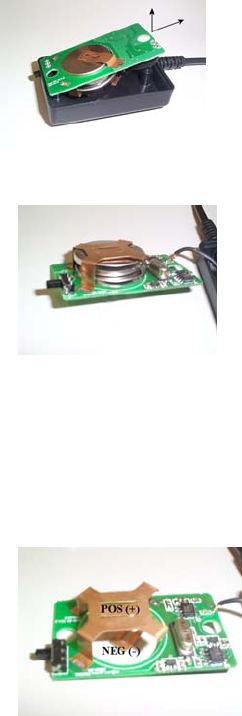
Battery Replacement
1. Remove the screws from the rear cover.
2. Remove the rear cover.
3. Raise the LED end of the printed circuit board and slide it towards the LED to clear the
switch from the housing.
4. Raise the switch end of the printed circuit board to allow access to the batteries.
5. Remove the assembly from the housing.
6. Slide the top battery away from the slide switch and remove. Raise the lower battery
upward to clear the hole in the printed circuit board and slide it in a similar fashion.
7. Insert the replacement battery 1 with the (-) contact into the hole in the printed circuit
board. Insert replacement battery 2 (+) contact up, onto the top of battery 1. Replace the
assembly into the housing in a reverse manner.