Thermo Products Pride Burner 100N Users Manual This Page Contains Various Warnings Found Throughout The Highboy And Counterflow Condensing Gas Furnace Manual. Ple
125n to the manual c5d195a5-d0f5-4bf6-a230-0561dfb1d3d0
2015-02-03
: Thermo-Products Thermo-Products-Thermo-Pride-Burner-100N-Users-Manual-461605 thermo-products-thermo-pride-burner-100n-users-manual-461605 thermo-products pdf
Open the PDF directly: View PDF ![]() .
.
Page Count: 67
TWO STAGE CONDENSING GAS FURNACE
INSTALLATION AND OPERATION MANUAL
MODELS:
FOR USE WITH NATURAL GAS OR LP GAS (PROPANE)
CHX3-75N CDX3-75N
CHX3-100N CDX3-100N
CHX3-125N CDX3-125N
: IF YOU DO NOT FOLLOW THE SAFETY PRECAUTIONS BELOW AND IN THIS
MANUAL, A FIRE OR EXPLOSION MAY RESULT CAUSING PROPERTY DAMAGE, PERSONAL
INJURY, OR LOSS OF LIFE.
DO NOT STORE OR USE GASOLINE OR OTHER FLAMMABLE VAPORS AND LIQUIDS IN THE
VICINITY OF THIS OR ANY OTHER APPLIANCE.
WHAT TO DO IF YOU SMELL GAS:
• DO NOT TRY TO LIGHT ANY APPLIANCE.
• DO NOT TOUCH ANY ELECTRICAL SWITCH; DO NOT USE ANY PHONE IN YOUR BUILDING.
• LEAVE THE BUILDING IMMEDIATELY.
• IMMEDIATELY CALL YOUR GAS SUPPLIER FROM A NEIGHBOR’S PHONE. FOLLOW THE GAS
SUPPLIER’S INSTRUCTIONS.
• IF YOU CANNOT REACH YOUR GAS SUPPLIER; CALL THE FIRE DEPARTMENT.
INSTALLATION AND SERVICE MUST BE PERFORMED BY A QUALIFIED INSTALLER, SERVICE
AGENCY OR THE GAS SUPPLIER. (REFERRED TO IN THESE INSTRUCTIONS AS A QUALIFIED
HEATING CONTRACTOR).
PLEASE READ THESE INSTRUCTIONS PRIOR TO INSTALLATION, INITIAL FIRING, AND BEFORE
PERFORMING ANY SERVICE OR MAINTENANCE. THESE INSTRUCTIONS MUST BE LEFT WITH
THE HOMEOWNER AND SHOULD BE RETAINED FOR FUTURE REFERENCE BY QUALIFIED
SERVICE PERSONNEL.
THERMO PRODUCTS, LLC.
BOX 217
NORTH JUDSON, IN 46366
PHONE: (574) 896-2133 MADE IN USA
MG-1035
ECN 5222-MA 110815
All installations and services must be performed by qualified service personnel.
I. SAFETY INFORMATION
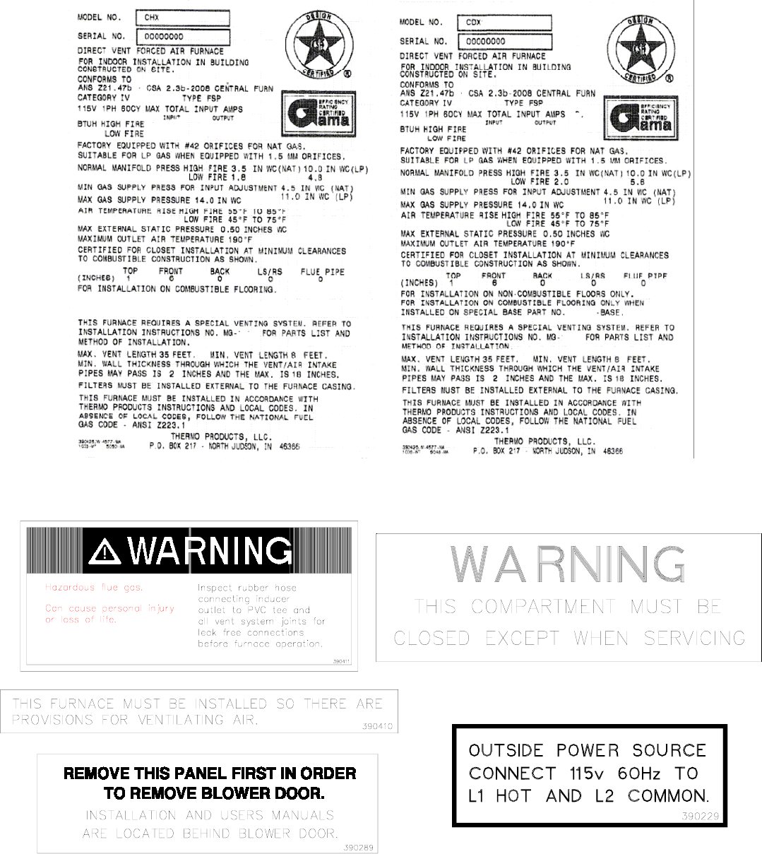
This and the following page contain reproductions of the various warning and instruction labels placed on
the Thermo Pride Two Stage Condensing Gas Furnaces. Please read and comply with the contents of
these labels.
i
All installations and services must be performed by qualified service personnel.
This and the previous page contain reproductions of the various warning and instruction labels placed on
the Thermo Pride Two Stage Condensing Gas Furnaces. Please read and comply with the contents of
these labels.
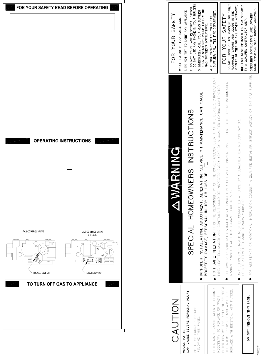
The following safety information should be read, understood, and followed by the installer.
WARNING: If you do not follow these instructions exactly, a
fire or explosion may result causing property damage,
personal injury or loss of life.
390540
1. Set thermostat to lowest setting, and, if equipped, set the operating
mode to "COOL" or "OFF".
2. If service is to be performed, turn off all electric power to the
appliance.
3. To turn off gas control valve, remove the burner compartment cover.
4. Move the gas control switch to the "OFF" position.
5. Replace the burner compartment cover.
1. STOP! Read the safety information above on this label.
2. Set the thermostat to the lowest setting.
3. Turn off all electric power to the appliance.
4. This appliance is equipped with a hot surface igniter that
automatically lights the burner. Do not try to light the burner by
hand.
5. Move the gas control switch to the "OFF" position.
6. Wait five (5) minutes to clear out any gas. Then smell for gas,
including near the floor or ground. If you smell gas, STOP! Follow
"B" in the safety information above on this label. If you don't smell
gas, go to the next step.
7. Move the gas control switch to the "ON" position.
8. Turn on all electric power to the appliance.
9. Set thermostat to desired setting, and, if equipped, set the operating
mode to "HEAT".
10.If appliance will not operate, follow the instructions "To Turn Off
Gas To Appliance" and call your service technician or gas supplier.
A. This appliance does not have a pilot. It is equipped with a hot
surface igniter that automatically lights the burner. Do not try to
light the burner by hand.
B. BEFORE OPERATING smell all around the appliance area for gas.
Be sure to smell next to the base of unit because some gas is
heavier than air and will settle on the floor or ground.
WHAT TO DO IF YOU SMELL GAS
? Do not try to light any appliance.
? Do not touch any electric switch; do not use any phone in your
building.
? Immediately call your gas supplier from a neighbor's phone.
Follow the gas supplier's instructions.
? If you cannot reach your gas supplier, call the fire department.
C. Use only your hand to move the gas control switch. Never use tools.
If the switch will not move by hand, don't try to repair it, call a
qualified service technician. Force or attempted repair may result in
a fire or explosion.
D. Do not use this appliance if any part has been underwater.
Immediately call a qualified service technician to inspect the
appliance and to replace any part of the control system and any gas
control which has been underwater.
ii
All installations and services must be performed by qualified service personnel.
1. Use only with type of gas approved for this furnace. Refer to furnace rating plate.
2. Connect this furnace to an approved vent system only. Combustion products must be carried
outdoors. Refer to Section III, D thru H, of this manual.
The following pages contain various warnings and cautions found throughout the Thermo Pride
Highboy and Dual Poise Two Stage Condensing Gas Furnace Manual. Please read and comply
with the statements below.
: This furnace is not to be used for temporary heating of buildings or structures under
construction.
: These high efficiency condensing furnaces are not certified for and shall not be
vented into a standard or any type of chimney.
: These furnaces may not be common vented with any other appliance.
: The vent and air intake elbows must be kept away from bushes, shrubs or any
vegetation that may restrict the flow of flue products. It must also be kept clear of any leaves,
weeds or other combustible materials. Keep the vent hood clear of snow. Avoid locating the
terminals in areas where standing water or condensate drippage may be a problem.
: This CHX3/CDX3 furnace has been designed to be installed as a direct vent system.
The failure to install the vent/air intake system as specified in these instructions will void the heat
exchanger warranty and may result in property damage, personal injury or loss of life.
: Outside combustion air must not come from an area that is directly adjacent to a
pool, hot tub or spa. Measures should be taken to prevent the entry of corrosive chemicals or
vapors to the combustion and ventilation air supply. Such chemicals include but are not limited to
chlorinated and/or fluorinated hydrocarbons such as found in refrigerants, aerosol propellants,
dry cleaning fluids, degreasers and removers. Other harmful compounds may come from
bleaches, air fresheners or mastics. Vapors from such products can form acid compounds when
burned in a gas flame. Should acid compounds form in your furnace; it may reduce the life of the
furnace.
: Because of the potential of odorant fade, a gas leak may not be detected by smell. If
this furnace is installed below grade, contact your gas supplier for a gas detector.
: Turn off power to furnace before it is placed into service. The gas piping system
must have been leak tested by a qualified heating contractor.
: It may be necessary to purge the air out of the gas line for initial start-up of the
furnace after installation. This should be done by a qualified heating contractor. If excessive gas
escapes when purging the gas supply at the union, allow the area to ventilate for at least 15
minutes before attempting to start the furnace. LP gas is especially dangerous because the
specific gravity of LP gas allows it to accumulate at floor level at a dangerous concentration. For
remainder of operating instructions, reference Users Information Manual.
: Heat exchanger oil will burn off on initial firing creating an unpleasant odor. To
prevent this odor from occurring more than once, it is suggested that:
1. A window(s) be opened.
2. The thermostat set at highest setting.
3. The furnace remain running at conditions 1&2 for 30 minutes or until odor has dissipated.
iii
All installations and services must be performed by qualified service personnel.
: The CHX3/CDX3 furnace models are sealed combustion design, which does not
require an air shutter adjustment (air shutters are not used) for proper flame characteristics.
Burner box access cover must always be secured with all screws in place and tightened before
operating furnace.
: Personal injury or property damage could result from repair or service of this
furnace by anyone other than a qualified heating contractor. Only the homeowner/user routine
maintenance described in the Users Information Manual may be performed by the user.
iv

All installations and services must be performed by qualified service personnel.
INDEX
SECTION BEGINNING PAGE
I. SAFETY INFORMATION i
II. FURNACE SPECIFICATIONS 1
III. GENERAL INSTALLATION 6
A. CODES AND CLEARANCES 6
B. FURNACE LOCATION 7
B1.CDX3 HORIZONTAL APPLICATION 7
C. REPLACING EXISTING FURNACE FROM A COMMON VENT 9
D. GENERAL REQUIREMENTS FOR VENTING CHX3/CDX3 9
E. SIDEWALL VENTING 11
E1. SINGLE PIPE (SIDEWALL) VENTING OPTION 15
F. INSTALLATION OF OUTSIDE VENT/AIR INTAKE TERMS. 15
G. CONNECTING FURNACE TO ROOF VENT/AIR TERMS. 17
H. CONNECTING FURNACE TO VENT/AIR INTAKE TERMS. 18
I. CONDENSATE DRAIN LINE & TRAP ASSY. 23
J. GENERAL GAS PIPING 26
J1. REQUIREMENTS AND SIZING OF DUCTWORK 27
K. FILTERS 30
L. WIRING 32
IV. STARTING THE UNIT 36
A. SEQUENCE OF OPERATIONS 36
B. INITIAL START-UP 39
C. MEASURING AND ADJUSTING HEAT INPUT RATE 70
D. FURNACE CHECKOUT PROCEDURE 47
V. INSTALLER’S INSTRUCTIONS TO USER 47
VI. TROUBLESHOOTING 48
APPENDIX – A REPLACEMENT PARTS LIST 55
APPENDIX – B WIRING DIAGRAMS 59
WARRANTY 61
v

All installations and services must be performed by qualified service personnel.
II. FURNACE SPECIFICATIONS
CHX3 SERIES
MODEL NO. CHX3-75 CHX3-100 CHX3-125
BTU/HR INPUT (High fire/ Low fire) 75,000 / 52,000 100,000 /
70,000 125,000 /
87,500
BTU/HR OUTPUT (High fire/ Low fire) 71,000 / 49,000 95,000 / 66,000 115,000 /
82,000
HEIGHT OF CASING 44-1/4” 44-1/4” 44-1/4”
WIDTH OF CASING 17” 21” 24”
DEPTH OF CASING 27-1/2” 27-1/2” 27-1/2”
WARM AIR OUTLET 15 x 18 19 x 18 22 x 18
RETURN AIR INLET 25 x 16 25 x 16 25 x 16
DIA. OF FLUE 2” 3” 3”
DIA. OF COMBUSTION
AIR INTAKE 2” 3” 3”
CFM from .2” & .5” w.c.
EXTERNAL STATIC PRESSURE COOLING COOLING COOLING
@COOLING TAP A 1000 1200 1400
@COOLING TAP B 800 1000 1200
@COOLING TAP C 1200 1400 1600
@COOLING TAP D 1400 1600 2000
HEATING HEATING HEATING
@HEATING TAP A (High fire/Low fire) 931 / 760 1243 / 1015 1556 / 1270
TEMPERATURE RISE 70 / 60 70 / 60 70 / 60
BLOWER MOTOR HP .5 .75 1
POWER CHOKES - 2.65 Mh 2.1 Mh
LARGEST RECOMMEDED
AIR CONDITIONER 3.5 Ton 4 Ton 5 Ton
SIZE OF FILTERS 24-3/4” x 15-3/4” 24-3/4” x 15-3/4” 24-3/4” x 19-3/4”
NOTES:
1. BTU output based on annual fuel utilization efficiency rated by manufacturer.
2. On all outlet and inlet dimensions, the first dimension is width.
3. To permit largest recommended air conditioning (at .5 static pressure), selection of the highest motor speed is
required.
1

All installations and services must be performed by qualified service personnel.
CDX3 SERIES
MODEL NO. CDX3-75 CDX3-100 CDX3-125
BTU/HR INPUT (High fire / Low fire) 75,000 / 56,250 100,000 /
75,000 125,000 /
93,750
BTU/HR OUTPUT (High fire / Low fire) 71,000 / 52,000 94,000 / 69,000 116,000 /
87,000
HEIGHT OF CASING 46-1/4” 46-1/4” 46-1/4”
WIDTH OF CASING 17” 21” 24”
DEPTH OF CASING 27-1/2” 27-1/2” 27-1/2”
WARM AIR OUTLET 15 x 18 19 x 18 22 x 18
RETURN AIR INLET 15 x 22 19 x 22 22 x 22
DIA. OF FLUE 2” 3” 3”
DIA. OF COMBUSTION
AIR INTAKE 2” 3” 3”
CFM from .2” & .5” w.c.
EXTERNAL STATIC PRESSURE COOLING COOLING COOLING
@COOLING TAP A 1000 1200 1400
@COOLING TAP B 800 1000 1200
@COOLING TAP C 1200 1400 1600
@COOLING TAP D 1400 1600 2000
HEATING HEATING HEATING
@HEATING TAP C (High fire / Low
fire) 1012 / 826 1340 / 1094 1673 / 1366
TEMPERATURE RISE 65 / 60 65 / 60 65 / 60
BLOWER MOTOR HP .5 .75 1
POWER CHOKES - 2.65Mh 2.1Mh
LARGEST RECOMMEDED
AIR CONDITIONER 3.5 Ton 4 Ton 5 Ton
SIZE OF FILTERS 21-3/4” x 14”(2) 21-3/4” x 14”(2) 21-3/4” x 14”(2)
NOTES:
1. BTU output based on annual fuel utilization efficiency rated by manufacturer.
2. On all outlet and inlet dimensions, the first dimension is width.
3. To permit largest recommended air conditioning (at .5 static pressure), selection of the highest motor
speed is required.
4. Electrical characteristics at 115 volts, 60 Hz., 1 phase (less than 15 amps. for all models).
5. All specifications are subject to change without notice.
2
All installations and services must be performed by qualified service personnel.
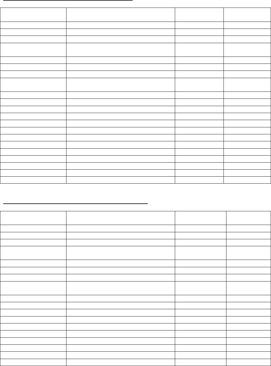
INSTALLATION PARTS PACKAGES – CHX3-75
PARTS PACKAGE
#S00S4413 DESCRIPTION PART # QUANTITY
2-3/8” ID radiator hose 410017 1
Thermostat lead bushing 350750 1
PVC trap assembly 320816 1
#8 x ¾ coated TEK screws for
mounting trap & inlet/outlet collars 300283 4
11/16” OD x 1/2” ID vinyl tubing 410060 24”
2 x 4 electrical J-box 350024 1
2 x 4 electrical J-box cover 350020 1
#8 x ½ TEK screws for
mounting 2 x 4 J-box 300208 2
#10-32 x ½ green ground screw 300109 1
#10-32 hex nut 300110 1
3/16” dia. star washer 300270 1
Grounding instructions MG-966 1
Wire nut 300132 2
3” stainless steel hose clamp 300276 2
J-box wire bushing 350016 1
Drain hose grommet 350446 1
Spring clamp, 11/16” 300299 3
Installation notice MG-987 1
PVC tee assembly, 2” dia. 320818 1
CPVC XPVC adapter 320833 1
Gas Conversion Kit AOPS7682 1
INSTALLATION PARTS PACKAGES – CHX3-100-125
PARTS PACKAGE
#S00S4414/4415 DESCRIPTION PART # QUANTITY
2-3/8” ID radiator hose 410017 1
Thermostat lead bushing 350750 1
PVC trap assembly 320816 1
#8 x ¾ coated TEK screws for
mounting trap & inlet/outlet collars 300283 4
11/16” OD x ½” ID vinyl tubing 410060 24”
2 x 4 electrical J-box 350024 1
2 x 4 electrical J-box cover 350020 1
#8 x ½ TEK screws for
mounting 2 x 4 J-box 300208 2
#10-32 x ½ green ground screw 300109 1
#10-32 hex nut 300110 1
3/16” dia. star washer 300270 1
Grounding instructions MG-966 1
Wire nut 300132 2
3” stainless steel hose clamp 300276 2
J-box wire bushing 350016 1
Drain hose grommet 350446 1
Spring clamp, 11/16” 300299 3
Installation notice MG-987 1
3
All installations and services must be performed by qualified service personnel.
PVC tee assembly, 2 x 3” dia. 320817 1
CPVC XPVC adapter 320833 1
Gas Conversion Kit AOPS7683/7419 1
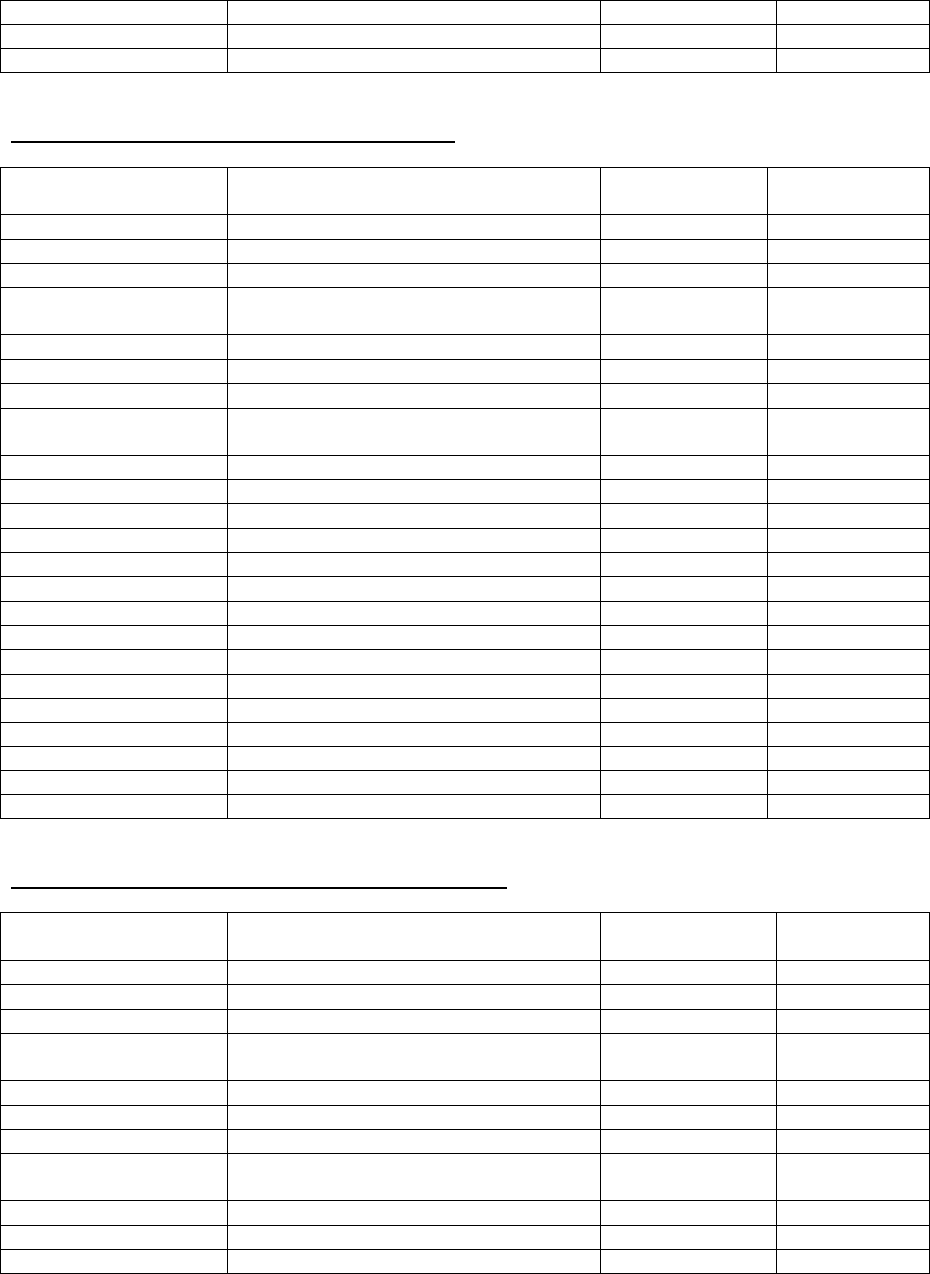
INSTALLATION PARTS PACKAGES – CDX3-75
PARTS PACKAGE
#S00S4416 DESCRIPTION PART # QUANTITY
2-3/8” ID radiator hose 410017 1
Thermostat lead bushing 350750 1
PVC trap assembly 320816 1
#8 x ¾ coated TEK screws for
mounting trap & inlet/outlet collars 300283 6
11/16” OD x ½” ID vinyl tubing 410060 24”
2 x 4 electrical J-box 350024 1
2 x 4 electrical J-box cover 350020 1
#8 x ½ TEK screws for
mounting 2 x 4 J-box 300208 2
#10-32 x ½ green ground screw 300109 1
#10-32 hex nut 300110 1
3/16” dia. star washer 300270 1
Grounding instructions MG-966 1
Wire nut 300132 2
3” stainless steel hose clamp 300276 2
J-box wire bushing 350016 1
Drain hose grommet 350446 1
Spring clamp, 11/16” 300299 3
Installation notice MG-987 1
PVC tee assembly, 2” dia. 320819 1
Pipe 2” dia. PVC 15” 14401 1
Bracket 14406 1
CPVC XPVC adapter 320833 1
Gas Conversion Kit AOPS7682 1
INSTALLATION PARTS PACKAGES – CDX3-100-125
PARTS PACKAGE
#S00S4381 DESCRIPTION PART # QUANTITY
2-3/8” ID radiator hose 410017 1
Thermostat lead bushing 350750 1
PVC trap assembly 320816 1
#8 x ¾ coated TEK screws for
mounting trap & inlet/outlet collars 300283 4
11/16” OD x 1/2” ID vinyl tubing 410060 24”
2 x 4 electrical J-box 350024 1
2 x 4 electrical J-box cover 350020 1
#8 x ½ TEK screws for
mounting 2 x 4 J-box 300208 2
#10-32 x ½ green ground screw 300109 1
#10-32 hex nut 300110 1
3/16” dia. star washer 300270 1
4

All installations and services must be performed by qualified service personnel.
Grounding instructions MG-966 1
Wire nut 300132 2
3” stainless steel hose clamp 300276 2
J-box wire bushing 350016 1
Drain hose grommet 350446 1
Spring clamp, 11/16” 300299 3
Installation notice MG-987 1
PVC tee assembly, 2 x 3” dia. 320817 1
PVC tee assembly, 2” dia. 320819 1
Pipe 2” dia. PVC 15” 14401 1
Bracket 14406 1
Reducer 2” x 3” PVC 320067 1
CPVC XPVC adapter 320833 1
Gas Conversion Kit AOPS7683/7419 1
5
All installations and services must be performed by qualified service personnel.
III. GENERAL INSTALLATION
These Category Type IV furnaces are shipped completely assembled and wired (internally). See the
Dealer Receiving and Freight Claim Procedure Section of the price guide for parts shortage or damage.
The furnace and duct system must be adjusted to obtain a temperature rise of 55°F to 85°F through the
furnace after installation. (See rating label located on side panel inside the furnace vestibule). The
installation must conform with local codes, or in the absence of local codes, with the National Fuel Gas
Codes (ANSI Z223.1 or latest edition) and with these instructions.
: This furnace is not to be used for temporary heating of buildings or structures under
construction.
Many of the chemicals used during construction, when burned, form acid bearing condensate that can
substantially reduce the life of the heat exchanger.
It is recommended that a commercially available CO alarm be installed in conjunction with any fossil fuel
burning appliance. The CO alarm shall be installed according to the alarm manufacturer’s installation
instructions and be listed in accordance with latest edition of the UL Standard for Single and Multiple
Station Carbon Monoxide Alarms, UL 2034, or the CSA International Standard, Residential Carbon
Monoxide Alarming Devices, CSA 6.19.
A. CODES AND CLEARANCES
The following items must be considered when choosing the size and location of the furnace.
1. All local codes and/or regulations take precedence over the instructions in this manual and should be
followed accordingly. In the absence of local codes, installation must conform with these instructions,
regulations of the National Fire Protection Association, provisions of National Electrical Code
(ANSI/NFPA70 or latest edition), and the National Fuel Gas Code (ANSI Z223.1 or latest edition).
2. The BTU output capacity of the furnace proposed for installation should be based on a heat loss
calculation made according to the manuals provided by the Air Conditioning Contractors of America
(ACCA) or ASHRAE.
3. MINIMUM CLEARANCES TO COMBUSTIBLE MATERIALS
TABLE 1
MODEL NO. FROM SIDES OF
FURNACE & REAR FRONT TOP OF
PLENUM FROM THE
FLUE OR VENT SIDE OF
PLENUM
CHX3-75 0 IN. 6 IN. 0 IN. 0 IN. 1 IN.
CHX3-100 0 IN. 6 IN. 0 IN. 0 IN. 1 IN.
CHX3-125 0 IN. 6 IN. 0 IN. 0 IN. 1 IN.
CDX3-75 0 IN. 6 IN. 0 IN. 0 IN. 1 IN.
CDX3-100 0 IN. 6 IN. 0 IN. 0 IN. 1 IN.
CDX3-125 0 IN. 6 IN. 0 IN. 0 IN. 1 IN.
The CHX3-75, 100 and 125 furnaces may be installed on combustible flooring. The furnace shall not be
installed directly on carpeting, tile or other combustible material other than wood flooring.
The CDX3-75, 100 and 125 furnaces are to be installed on non-combustible flooring only. The non-
combustible floor bases model no. 50 DA base for CDX3-75 model no. 100 CA base for the model no.
CDX3-100 and model no. 125 CA base for CDX3-125 are available for the counterflow furnaces to allow
their installations on combustible flooring.
6

All installations and services must be performed by qualified service personnel.
These furnaces may be installed in an alcove or in a closet if the minimum clearances to combustible
construction (listed previously) are met. The CDX3 series furnaces may be installed in an attic or crawl
space. Refer to section III, B1 of this installation manual.
The minimum clearances are listed for fire protection. Clearance for servicing the front of the furnaces
and to all points on the furnace requiring access must be 24”*.
*For horizontal furnace installation, refer to section III, B1 of this installation manual.
Equipment must be installed in accordance with regulations of the National Board of Fire
Underwriters. Authorities having jurisdiction should be consulted before installations are made.
B. FURNACE LOCATION
: These high efficiency condensing furnaces are not certified for and shall not be
vented into a standard or any type of chimney.
The following shall be considered for locating the furnace:
1. For best performance locate the furnace so that it is centralized with respect to the duct system and
as near as possible to a floor drain since condensate drainage must be provided.
2. Place the unit so that proper venting can be achieved, with a minimum number of elbows, in accord
with the instructions in this manual.
3. The furnace must be located on a level, dry surface. The furnace must be installed so that the
electrical components are protected from water. If the area becomes wet or damp at times, the
furnace should be raised above the floor using a concrete base, bricks, patio blocks, etc.
NOTICE: Ensure furnace is level after installation to ensure proper drainage and operation.
4. This furnace must be connected to a drain in accordance with these instructions. If it is not practical
to connect the unit to a drain, a condensate pump must be used and can be ordered as an
accessory, part number 350225. If an acid neutralizer kit is required by local code or the customer, it
is available under part number 320095.
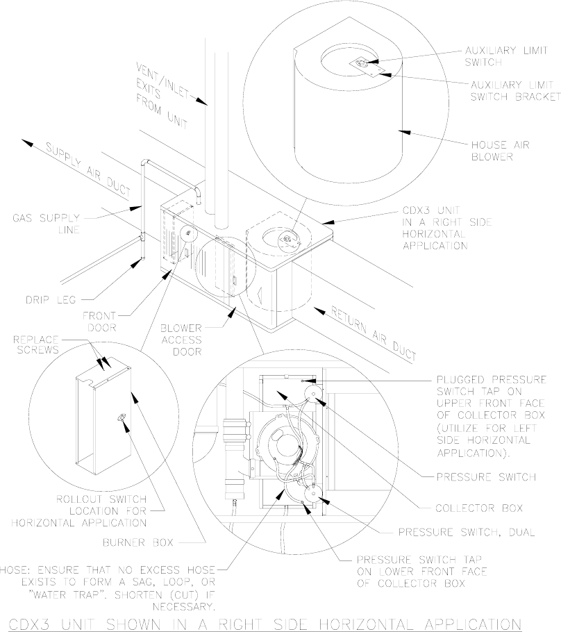
B1. CDX3 HORIZONTAL APPLICATION
The CDX3-75, 100, and 125 furnaces may be installed in a horizontal position by placing the furnace on
the left or right side (as viewed from the front in the upright position).
For left or right horizontal applications of the CDX3 series units, the rollout switch located on the burner
box must be moved to the pre-punched mounting holes on the side of the burner box. Screws are
provided in pre-punched holes at the required limit location. Remove these screws and use them to
mount the limit to new location. Utilize previously removed limit mounting screws to fill voided holes at
previous limit location (See Figure 1).
For a right side horizontal application of the CDX3 series units, the hose from the single tap pressure
switch (top switch) is already connected correctly (See Figure 1).
For a left side horizontal application of the CDX3 series units, the hose from the single tap pressure
switch (bottom switch) must be moved to the lower front tap on the face of the collector box. Use the
black cap removed from this tap to plug the original pressure switch tap.
7
All installations and services must be performed by qualified service personnel.
NOTE: The hose, when moved, must be shortened (cut) to ensure that no excess hose exists to cause a
sag, loop, or "water trap".
For a right side horizontal application of the CDX3 series units, the auxiliary limit switch located on the
right side of the house air blower must be moved to the bracket on the opposite (left) side of the blower
(See Figure 1).
NOTE: When the CDX3 is installed as horizontal unit, it is imperative that the auxiliary limit switch and
bracket be located on the upper side of the house air blower; the burner rollout switch located on the
burner box be relocated to the side of the burner box; and that the hose from the single tap pressure
switch be connected to the lower tap on the front of the collector box (See Figure 1).
Figure 1
8

All installations and services must be performed by qualified service personnel.
The horizontal furnace installation should be on a service platform large enough to allow for proper
clearances on all sides and service access to the front of the furnace (See Table 1). If the furnace is
suspended, it must be supported at both ends and in the middle with clearance allowed for removal of
both access doors. Gas supply line contact is only permissible between lines formed by the intersection
of the top and two sides of the furnaces casing and the building joists, studs, or framing (See Figure 1).
Equipment must be installed in accordance with regulations of the National Board of Fire
Underwriters and the National Fuel Gas Code. Authorities having jurisdiction should be consulted
before installations are made.
C. Replacing An Existing Furnace From A Common Vent
: These furnaces may NOT be common vented with any other appliance.
D. General Requirements For Venting Models CHX3 / CDX3
The CHX3 / CDX3 furnace venting system must be installed by a qualified service person in
accordance with local installation codes and these instructions. In the absence of applicable local
codes, conform to the National Fuel Gas Code, NFPA 54 /ANSI Z223.1-2002, or latest edition
thereof.
Installation shall, at least, conform to the following requirements.
1. The exhaust vent / combustion air intake terminations specified by Thermo Products, in this
manual, shall be used.
2. All plastic pipe and pipe fittings sourced to complete the exhaust vent and air intake
systems shall be constructed of rigid PVC (polyvinyl chloride) thermoplastic. All
components shall have a wall thickness equivalent to Schedule 40 series materials.
In addition, all sourced PVC components shall be listed by a nationally recognized testing agency
(e.g. NSF, UL, etc.) as conforming to one (1) or more of the following design standards.
PVC Pipe Designation Design Standard
Cellular Core ASTM-F891
DWV (Drain-Waste-Vent) ASTM-D2665
Schedule 40 ASTM-D1785
3. The exhaust vent pipe and combustion air pipe shall be at least as large as the exhaust vent / air
intake pipe specified by Thermo Products. Size reduction is never permissible. The required
exhaust vent / air intake pipe sizes are:
• nominal 2-inch diameter IPS, Schedule 40 series, PVC thermoplastic pipe, for models
CHX3-75 & CDX3-75, or
• nominal 3-inch diameter IPS, Schedule 40 series, PVC thermoplastic pipe, for models
CHX3-100 / -125 & CDX3-100 / -125.
4. The furnace model series CHX3 / CDX3 shall not be common vented with any other appliance,
including those burning solid fuels.
9

All installations and services must be performed by qualified service personnel.
5. All horizontal runs of exhaust vent pipe shall slope upward at least ¼ inch per foot from the outlet
of the furnace (for model CHX3), or the outlet of the drain tee (for the model CDX3), to the vent
termination, beyond the outside wall. This slope will permit proper drainage of the condensate.
Horizontal runs of air intake pipe shall slope downward at least ¼ inch per foot from the outlet of
the last elbow or last horizontal run, before exiting the wall, to the intake termination beyond the
outside wall. This slope will permit proper drainage of any precipitation that enters the intake
pipe.
6. The exhaust vent pipe shall be supported at every joint (no more than 4-feet between supports)
to prevent pipe blockage due to condensate trapped at a local low point, or sag, in the vent
system.
7. The maximum permissible length of piping (consisting of a combination of straight pipe and a
corresponding number of elbows) permitted is:
• 75 equivalent feet, for the exhaust vent system, and
• 70 equivalent feet, for the combustion air intake system.
8. The maximum quantity of Schedule 40 series, type DWV thermoplastic pipe elbows allowed in
each system is listed in Table 2. When counting pipe elbows, all elbows used in the exhaust vent
or combustion air intake systems must be considered. This includes all elbows, or equivalent
pipe fittings, used inside the furnace jacket in addition to those used to construct the termination.
Furthermore, a credit of 5-feet of straight pipe may be taken for each elbow, up to maximum of
three (3) elbows, which is dropped from the maximum permissible number for each system.
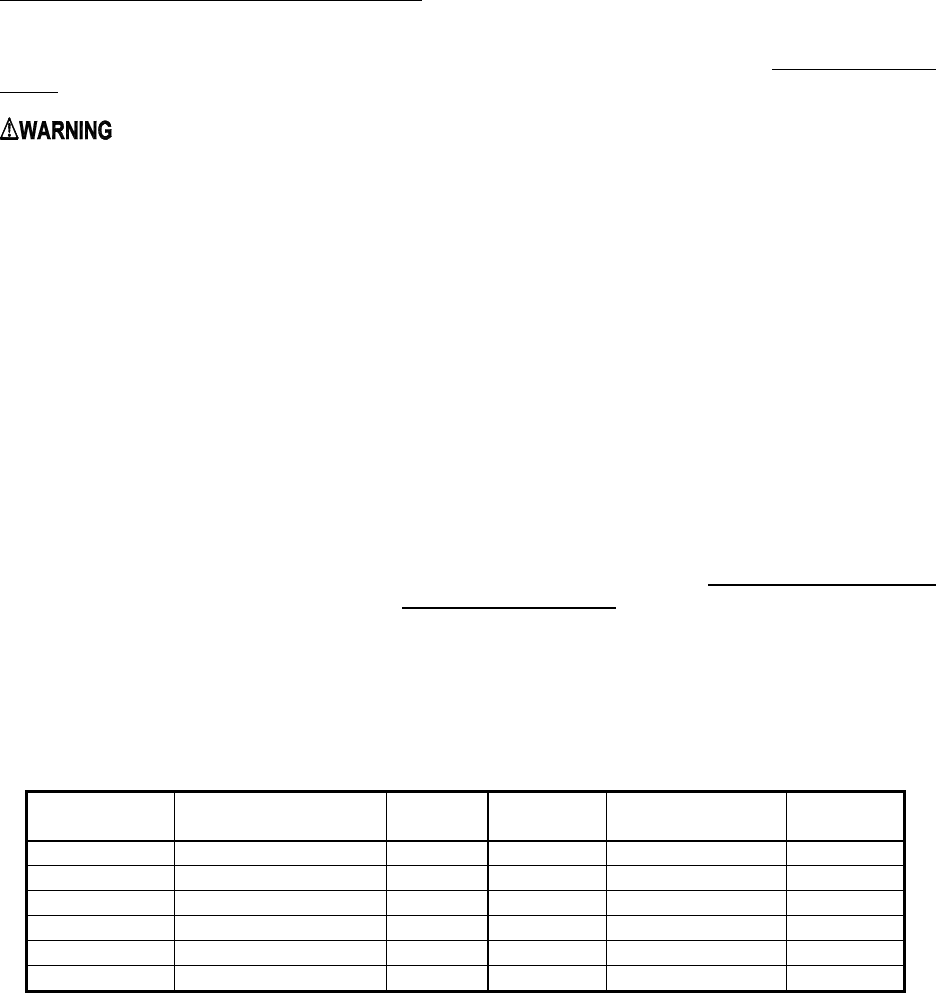
Table 2: Maximum Permissible Exhaust Vent and Combustion Air Intake Lengths When Using the
Maximum Quantity of Elbows
Thermoplastic
Pipe Vent Size
(Nominal)
2 in. Diameter IPS
3 in. Diameter IPS
Furnace Model Exhaust or
Intake
Straight
Pipe Length
(ft.)
Maximum Qty.
of Exhaust
Elbows 1, 2
Maximum
Qty. of Intake
Elbows 2
Exhaust or
Intake
Straight Pipe
Length (ft.)
Maximum Qty.
of Exhaust
Elbows 1, 2
Maximum
Qty. of Intake
Elbows 2
CHX3 / CDX3-75 35 8 7 - - -
CHX3 / CDX3-100
CHX3 / CDX3-125 Not Permitted
35
8
7
Superscripts:
1 The drain tee supplied with the model series CHX3 / CDX3 furnaces is considered
equivalent to one (1), 90° elbow.
2 Two (2) 45° elbows can be substituted for one (1), 90° elbow.
Care should be taken to design the shortest possible intake and exhaust systems. Each system
should contain as few elbows as possible to insure the satisfactory operation of the furnace.
However, system length should never be less than 8 ft of pipe with two (2), 90 deg. elbows.
For best overall operation of the combustion system, we recommend the actual equivalent
lengths for both the constructed intake and the exhaust systems have approximately the same
value.
9. Use a saw designed to cut thermoplastic pipe. All cuts should be made at right angles to the pipe
wall. Smooth jagged edges and remove all burrs and strings. All pipe joints must utilize
standard PVC Schedule 40 series, DWV type elbows, couplings, and fittings. Clean all pipe
surfaces at connections using a fine abrasive material or approved PVC cleaner (primer). Secure
10
All installations and services must be performed by qualified service personnel.
all pipe joints using suitable permanent PVC pipe solvent cement. Joints are NOT to be made by
simply gluing raw edges of butted together vent pipe.
The piping joints inside the furnace vestibule should be sealed with a silicone caulk, rather than
pipe cement, to allow for disassembly and removal of piping, if necessary, during maintenance.
NOTICE: DO NOT use silicone caulk to seal the pipe sleeve or coupling to the metal air
intake collar on the burner box. Securing the sleeve or coupling to the collar using a screw
is sufficient.
10. Vent connections shall be checked for leakage with the furnace induced draft blower running and
with the vent termination blocked. Use a mild soap and water solution to check for leaks.
11. Vent pipe passing through an unheated space shall be insulated with 1-inch thick, foil-faced
fiberglass insulation, or equivalent, to prevent freezing of condensate within the pipe.
12. No clearance is required from the outer surface of the thermoplastic piping to combustible
materials for fire hazard prevention.
13. Thermo Products does not require screens be installed in the exhaust vent and air intake piping.
However, optional stainless steel screens are available from Thermo Products, should the
homeowner request them.
NOTICE: The CHX3 / CDX3 furnace models may be vented either through the sidewall or the roof.
For sidewall instructions, continue to the following section. For roof venting, refer to Section III G, of
this manual.
E. Direct Venting Through a Sidewall
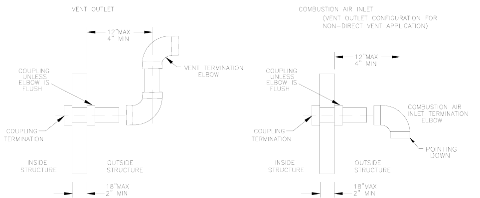
1. Vent and combustion air pipes may pass through a maximum wall thickness of 18 inches. The
minimum wall thickness is 2 inches. Referring to Figure 2, the maximum distance from the outer
wall to the center of the elbow is 12 inches.
Figure 2: Proper Direct Vent Terminations (RH & LH views) and Vent Termination Only w/o
Outside Combustion Air Intake (RH view).
11
All installations and services must be performed by qualified service personnel.
NOTICE: If exterior sidewall building materials are subject to degradation from contact with flue gases or
moisture, a minimum 24-inch diameter shield shall be fabricated from stainless steel or UV-resistant
plastic sheet. The protective shield shall be installed around the vent pipe on the outside wall.
2. The exhaust vent termination elbow shall be installed in accordance with these instructions and
any applicable local codes. Refer to Figures 2 and 3 for typical examples of proper terminations.
a. The exhaust vent termination must be installed in the same atmospheric pressure zone (i.e.
on the same wall) as the air intake termination.
b. The bottom edge of the vent termination elbow must be installed at least 12-inches above the
outlet of intake termination elbow.
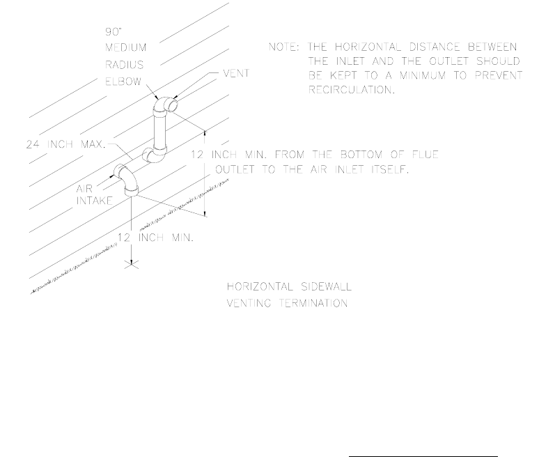
c. The horizontal distance between the inlet and exhaust terminations should be minimized,
when possible, and should never exceed 24-inches.
d. The vent and intake systems should utilize the same numbers of elbows and approximately
the same length of straight pipe to reach the outside termination.
Figure 3: Typical Relative Locations of Direct Vent Terminations When Sidewall Venting.
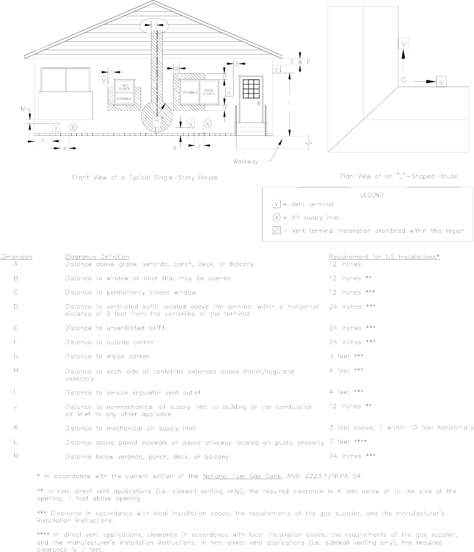
3. Exhaust Vent Terminal Location Clearance Requirements
a. The vent terminal shall be located at least 3-feet above any forced air inlet located within 10-
feet. Refer to Figure 4 for a depiction of the required minimum clearances between vent
terminations and building features according to the National Fuel Gas Code (NFGC).
b. The vent terminal shall be at least 12-inches below, 12-inches horizontally from, or 12-inches
above, any door, window, or gravity air inlet into a building. The bottom of the vent terminal
shall be located at least 12-inches above grade.
c. The vent terminal shall not be located:
• over public walkways or over an area where wetting of surfaces by condensate, or water
vapor, could create a nuisance or hazard,
12
All installations and services must be performed by qualified service personnel.
• near soffit vents, crawl space vents, or other areas where condensate or water vapor
could create a nuisance, hazard, or cause property damage, and
• where wetting of components by condensate, or water vapor, could be detrimental to the
operation of pressure regulators, relief valves, or any other equipment.
d. The vent terminal shall be installed a minimum of 14-inches from any obstruction and 3-feet
from an inside corner of an L-shaped structure.
13
All installations and services must be performed by qualified service personnel.
Figure 4: NFGC Minimum Clearances Between the Vent Terminal and Various Building Features
Vent Terminal Location Guidelines
14

All installations and services must be performed by qualified service personnel.
: Bushes, shrubs, or any vegetation that may restrict the flow of flue products
must be kept away from vent and air intake terminations. Terminations must also be kept
clear of any leaves, weeds, combustible materials, snow, and ice build-up. Avoid locating
the vent terminal over areas where dripping of condensate, or small pools of acidic
condensate, could create a problem.
In addition to following any local code requirements, when possible, utilize the guidelines below in
locating the vent terminal to help insure trouble-free operation of a sidewall vented furnace:
• Avoid locating the vent terminal on a wall facing prevailing winds and wide-open areas. When
impractical, choose a location that protects the vent from strong winds, such as behind a
fence or hedge.
• In geographical areas with considerable snowfall, it is advisable to locate the vent terminal
much higher than the minimum 12-inches above ground to prevent blockage by snow
accumulation or drifting.
• The vent and combustion air terminations shall be checked periodically, at least at the start of
each heating season, for restriction or blockage from foreign material in the exhaust vent or
in the air intake piping. Clean the air intake and vent terminations when necessary.
E1. Single-Pipe (Sidewall) Venting Option
NOTICE: When possible, we recommend all model series CHX3 / CDX3 furnaces be installed
to utilize outside combustion air. The use of outside combustion air usually results in the
most energy efficient, nuisance free, and long-lived operation of the furnace.
NOTICE: Heat exchanger failure accelerated by contaminated combustion air will void the
furnace heat exchanger limited lifetime warranty.
This furnace may be horizontally, i.e. sidewall, vented using an exhaust vent pipe alone without
drawing in outside combustion air. When single-pipe, sidewall venting a furnace, combustion air is
drawn from the indoor space. This type of installation is not classified as a direct vent installation.
However, the same exhaust venting guidelines apply as for a direct vent installation, except the
exhaust termination will be similar to the air intake of the "two- pipe", direct vent installation. Refer to
depictions of proper intake terminal installations in Figures 2 and 3. Referring to the left-hand (LH)
sketch in Figure 2, vent termination will consist of one (1), 90° elbow, opening downward.
When indoor air is used for combustion, measures should be taken to prevent drawing in corrosive
chemicals vapors or gases with the combustion air supply. Such chemicals include, but are not
limited to, chlorinated and/or fluorinated hydrocarbons such as found in refrigerants, aerosol
propellants, dry cleaning fluids, degreasers and removers. Other harmful compounds may come from
bleaches, air fresheners or mastics. Vapors from such products can form reactive acid producing
chemical species when burned in a gas flame. The life of the furnace could be reduced should acidic
compounds form within the furnace.
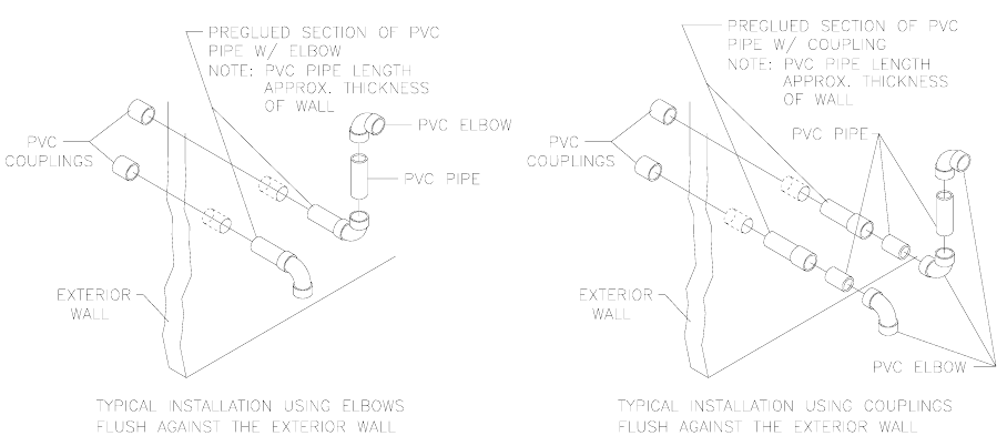
F. Installation Of Outside Exhaust / Intake Terminations
1. After determining appropriate installation locations (suitable locations must observe all
clearances specified in this manual), mark and cut two (2) holes in the outside wall of the
following sizes for the outdoor terminal(s),
a. 2-3/8 inch diameter, for furnace models CHX3 / CDX3-75, or
b. 3-1/2 inch diameter, for the furnace models CHX3 / CDX3-100 and CHX3 / CDX3-125.
15
All installations and services must be performed by qualified service personnel.
2. Measure and cut two (2), 2-inch diameter thermoplastic pipes 1-1/2 inches longer than the depth
of the wall. Cutting the pipe longer leaves a ¾ inch connection allowance at both ends of the
pipe. (For 3-inch diameter PVC pipe, leave a 3-inch allowance for end connections). Using PVC
pipe cement, glue a PVC elbow or coupling fitting to one (1) end of each pipe.
Before inserting the pipe through the wall, mark the other end of the pipe so the elbow orientation
can be determined. Also, if a protective shield (refer to Section E., passage 1. of this manual) will
be used on the exterior surface of the wall, it should be installed at this time. From the inside,
glue a coupling fitting to each pipe, using PVC pipe cement, while being careful to maintain the
proper orientation of the termination elbow(s). Complete the assembly of the outlet and inlet as
shown in Figure 5, making sure that the spacing between the inlet and outlet complies with that
noted in Figure 3.
Figure 5: Typical Sidewall Vent and Air Intake Termination Construction Details
3. Finish the vent installation by caulking the annulus to seal around the two (2) holes where the
thermoplastic pipes pass through the wall.
4. To prevent foreign material, insects, or small animals from entering the pipes, an optional vent or
intake terminal (stainless steel) screen is available from Thermo Products, 3”-part no. 320226, 2”-
part# 320219.
5. Optional Direct Vent Terminations
Three optional vent kits are available for direct vent terminations, refer to Figure 6.
• The concentric vent kits (Thermo Products p/n AOPS7488 & AOPS7489) provide a means
for the vent and intake to be installed through a single opening in the roof or exterior wall. Kit
p/n AOPS7488 requires a 4” inch diameter hole and is used on furnace models CHX3/CDX3-
75. Kit p/n AOPS7489 requires a 5” inch diameter hole and is used on furnace models
CHX3/CDX3-100 &125.
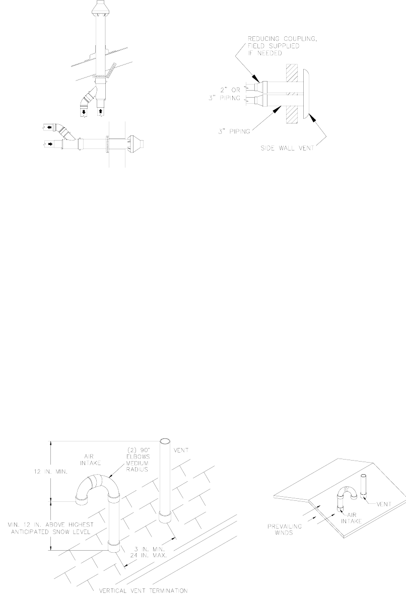
• The sidewall vent cap (Thermo Products part no. 370191) is a cover installed over the
exhaust vent and air intake pipes on the exterior of the building. For horizontal sidewall vent
applications only. This kit may be used on any size furnace in the CHX3/CDX3 family.
16
All installations and services must be performed by qualified service personnel.
Install these optional kits according to the instructions provided with each kit. The location and
clearance requirements are identical to those of the standard vent terminations described in this
manual.
370191
SIDE WALL VENT KIT
VERTICAL
HORIZONTAL
AOPS7488 / AOPS7489
CONENTRIC VENT KIT
Figure 6: Optional Direct Vent Kits for the CHX3 / CDX3 Model Series of Furnaces
G. Connecting The Furnace To Roof Exhaust / Intake Terminations
If it is not desirable, or feasible, to vent the furnace through a sidewall, it may be vertically vented
through the roof. Installation shall conform to the following guidelines, which are illustrated in
Figure 6A, below.
1. The outlet of the exhaust vent and the inlet of the combustion air intake, i.e. the terminations,
shall be a minimum of 12-inches above highest anticipated snow level.
2. The exhaust vent outlet must be installed a minimum of 12-inches above the air intake inlet.
3. Where exposed to prevailing winds, the combustion air intake shall be installed upwind of the
vent outlet.
4. The exhaust vent and combustion air intake can be a minimum of 3-inches and a maximum
of 24 inches apart.
NOTICE: When the vent termination is installed correctly, a draft should NOT be present in
the system during the furnace off-cycle.
Figure 6A: Typical Rooftop Vent and Air Intake Termination Construction Details
17
All installations and services must be performed by qualified service personnel.
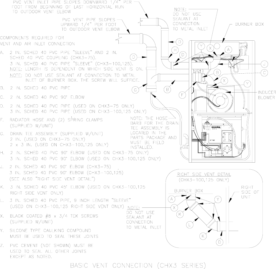
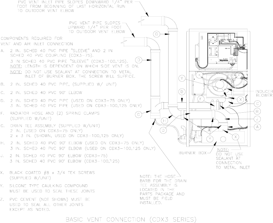
H. Exhaust / Intake Piping And Condensate Drain Connections At Furnace
1. Figures 6B, 7, and 8 follow depicting typical exhaust vent and air intake connections for the
furnace model series CHX3 and the CDX3, respectively, as well as a list of required parts to
correctly install each system.
Figure 6B: Required Exhaust Vent and Air Intake Piping for CHX3 Furnace
18
All installations and services must be performed by qualified service personnel.
Figure 7: Required Exhaust Vent and Air Intake Piping for CDX3 Furnace in Downflow
Applications
19
All installations and services must be performed by qualified service personnel.
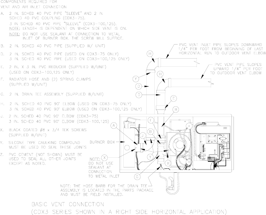
Figure 8: Required Exhaust Vent and Air Intake Piping for CDX3 Furnace in Horizontal
Applications.
2. Connecting The Exhaust Vent To The Inducer
a. Slip the end of the 2-inch diameter PVC elbow (for the model CDX3 in horizontal
applications, the 2-inch diameter PVC tee assembly) over the outlet of the inducer blower
assembly. Measure the length of 2-inch diameter thermoplastic pipe needed to clear the
furnace side casing, while allowing for installation of a 2-3/8 inch length of reinforced rubber
hose, used as a coupling, within the casing of the furnace. Cut the measured lengths of 2-
inch diameter PVC pipe being sure to allow a sufficient length of pipe for connections. Refer
to Figures 9, 10 and 11 for assembly details.
NOTICE: For the model CDX3-75, a length of 2-inch diameter PVC pipe and a 2-inch
diameter PVC tee assembly are supplied with each furnace. For the models CDX3-100 and
CDX3-125, a 3-inch x 2-inch diameter PVC reducer is also supplied.
NOTICE: For models CDX3-100 and CDX3-125 used in horizontal applications,
immediately transition from 2-inch to 3-inch diameter pipe by installing the 3-inch x 2-inch
diameter PVC reducer just outside the furnace casing. The remainder of the venting system
20
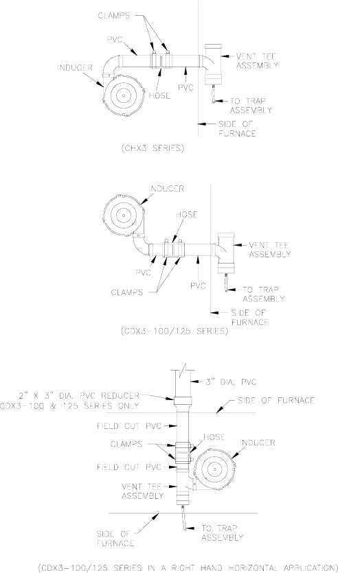
All installations and services must be performed by qualified service personnel.
leading away from the furnace must be composed of 3-inch diameter PVC pipe and pipe
fittings only. Refer to item E in Figure 8.
b. After preparation of the internal 2-inch diameter PVC pipe sections, put a thin bead of a ter )
the
ernal Vent Piping Arrangement for the Furnace Model Series CHX3.
Figure 10: Typical Internal Vent
100 / -
Figure 11: Typical Internal Vent
100 / -
c. Using PVC cement, glue the pre-cut 2-inch di
silicone rubber type sealant around the outlet flange of the inducer. Slip the 2-inch diame
PVC elbow (for the model series CDX3 in horizontal applications, a 2-inch diameter PVC tee
over the inducer outlet flange. Drive one (1) #8 x 3/4 inch sheet metal screw with black
protective coating (supplied with furnace) through the elbow and into the outlet flange of
inducer to secure the elbow in place.
Figure 9: Typical Int
Piping Arrangement for the
Furnace Model Series CDX3-
125.
Piping Arrangement for the
Furnace Model Series CDX3-
125 in RH Horizontal Applications.
ameter thermoplastic pipe, from step (a) above,
to the 2-inch diameter PVC elbow (for the model series CDX3 in horizontal applications, the
2-inch diameter PVC tee). Couple the drain tee assembly to the pre-cut 2-inch diameter PVC
pipe using the reinforced rubber hose and the two (2) band clamps supplied.
21

All installations and services must be performed by qualified service personnel.
NOTICE: All PVC thermoplastic pipe must be supported beginning directly over the
exhaust vent tee assembly, then every 4-feet thereafter, and at every joint. Trial fit the
entire exhaust vent and air intake piping systems, making sure the slope and length of the
piping are correct, before permanently assembling the pipe components.
If the vent piping is run through an unconditioned space, it must be insulated with 1-inch
thick, foil-faced fiberglass insulation, or an equivalent product.
3. Connecting The Combustion Air Intake Piping
: Outside combustion air must NOT be drawn from an area directly adjacent to
a pool, hot tub or spa. Measures should be taken to prevent the entry of corrosive
chemicals or vapors into the combustion air supply. Such chemicals include, but are not
limited to, chlorinated and/or fluorinated hydrocarbons such as found in refrigerants,
aerosol propellants, dry cleaning fluids, degreasers and removers. Other harmful
compounds may come from bleaches, air fresheners or mastics. Vapors from such
products can form reactive acid producing chemical species when burned in a gas flame.
Should acidic compounds form in the furnace they may significantly reduce the useful life
of the furnace.
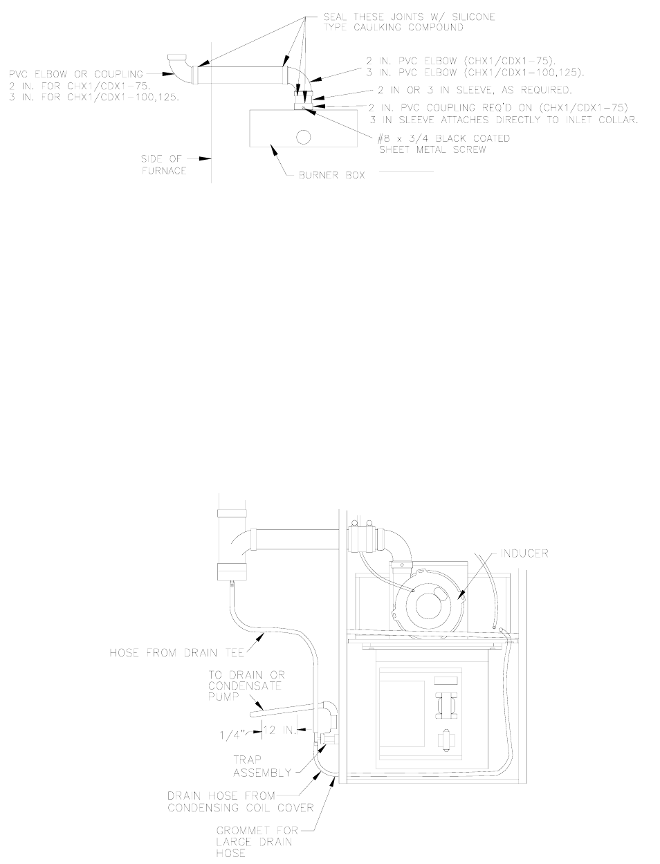
a. For the models CHX3 / CDX3-75, install a 2-inch PVC elbow with sleeve and coupling (for
models CHX3 / CDX3-100 & -125, a 3-inch PVC elbow with sleeve) on the inlet of the burner
box. Measure the length of pipe needed to clear the casing. Be sure to allow sufficient length
to account for insertion of the pipe into the elbow at the burner box and the elbow, or coupling
fitting, on the end. Cut the pipe to length.
b. After preparation of the thermoplastic pipe, drive one (1) #8 x 3/4 inch sheet metal screw with
black protective coating (supplied with furnace) through the PVC coupling, or sleeve, into the
metal collar of the burner box to secure the piping in place.
NOTICE: DO NOT apply silicone rubber type sealant or PVC cement to the joint at the
thermoplastic piping connection to the metal burner box collar. Attach the PVC elbow
to the sleeve and then to the coupling where required, using silicone rubber type
sealant, refer to Figure 12.
c. Insert the precut 2-inch (or 3-inch) thermoplastic pipe into the elbow at the burner box and to
the elbow, or coupler, just outside the furnace using a silicone rubber type sealant. To
properly make these seals, run a thin bead of silicone type sealant around the circumference
of the PVC pipe, about 3/8 inch from either end. Insert the straight pipe section into the
appropriate couplings and elbows and rotate 1/4 turn. Silicone rubber type sealants remain
pliable after the initial setup period has passed allowing for relatively easy disconnection of
the air intake system, should the burner assembly require removal at a later date, refer to
Figure 12.
NOTICE: When applying silicone sealants, ensure that no excess sealant is pushed
into the inside opening of the pipe. This may cause flow restriction within the piping. If
possible, always apply the sealant to the male component of the piping joint.
22
All installations and services must be performed by qualified service personnel.
DO NOT! SILICONE OR SEAL
THIS CONNECTION IN
ANYWAY. MUST BE LOOSE
FIT WITH LEAKAGE BETWEEN
PVC AND METAL COLLAR.
Figure 12: Typical Internal Air Intake Piping Arrangement for All Furnace Models
d. After trial fitting the entire combustion air intake system, use a PVC cement to glue all
connections in place, except the length of pipe between the combustion air fitting on the
burner box and the first fitting.
e. If the combustion air piping is installed in a warm, humid place, such as a laundry room or above a
suspended ceiling, it must be insulated with a 1-inch thick, foil-faced fiberglass insulation, or an
equivalent product, to help prevent the outside surface of the pipe from sweating.
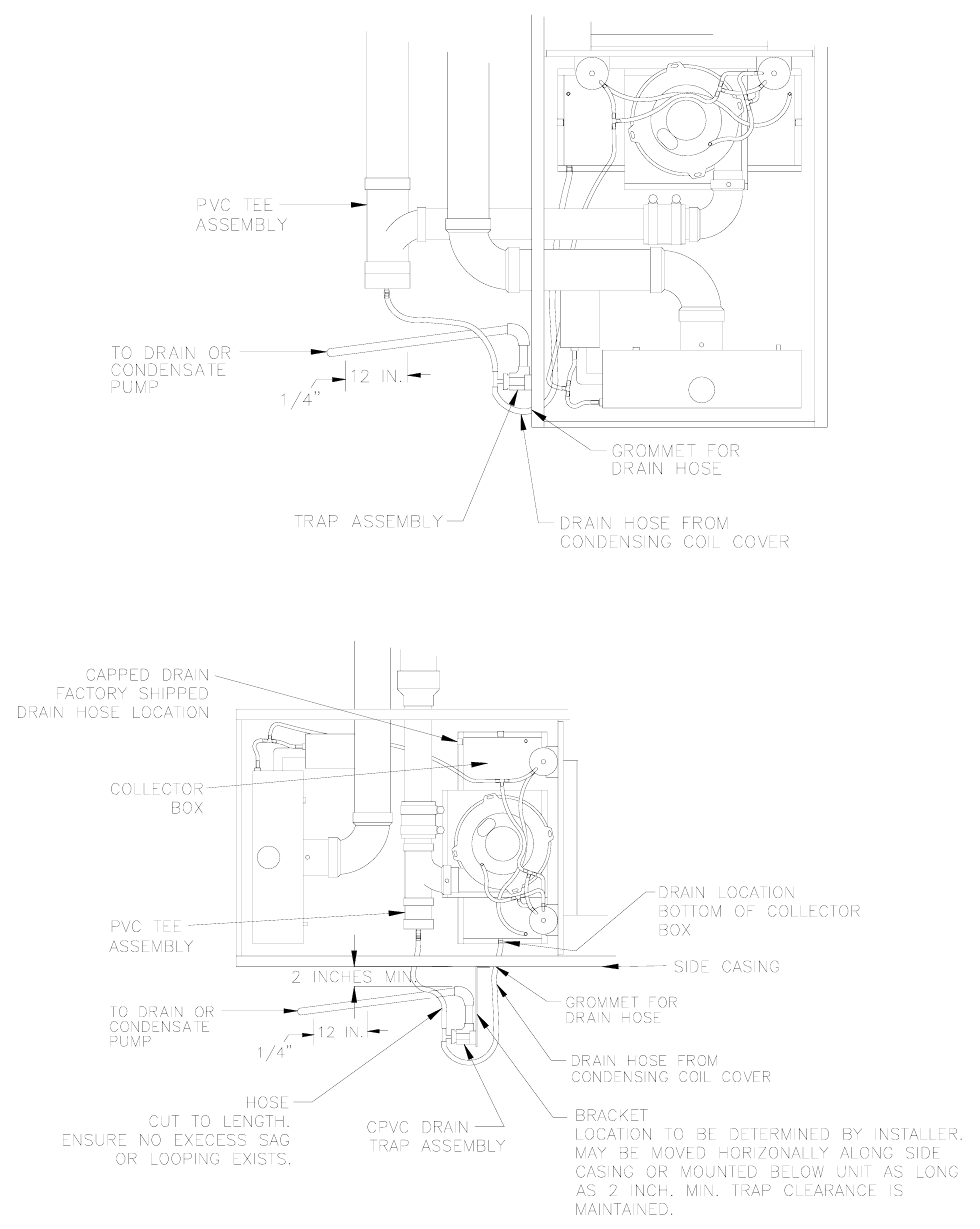
I. CONDENSATE DRAIN LINE AND TRAP ASSEMBLY
1. The following diagrams show the typical drain and trap connection for a CHX3 and CDX3 furnace.
Figure 14. TRAP ASSEMBLY MOUNTED ON CHX3
23
All installations and services must be performed by qualified service personnel.
Figure 15. TRAP ASSEMBLY MOUNTED ON CDX3
Figure 16. TRAP ASSEMBLY MOUNTED ON CDX3 RIGHT SIDE HORIZONTAL INSTALLATION
24

All installations and services must be performed by qualified service personnel.
2. Determine on which side of furnace the condensate disposal line is to be run (NOTICE: On
CHX3/CDX3’s this must be the same side as the flue outlet or bottom of unit). Attach the condensate
trap to the furnace casing using the #8x3/4” sheet metal screws provided in the parts package. Pilot
holes are provided on both sides of the casing for mounting.
NOTE: When the CDX3 series unit is used in a horizontal application, the drain hose from the
collector box will require a location change from it's factory shipped connection. A knockout has
been provided in the unit side casing for the drain hose to exit. The connection change can be
accomplished as follows: Refer to Figure 16.
a) Locate and disconnect the drain hose at the collector box from its factory shipped connection
location.
b) Locate and uncap the drain at the bottom (as it is oriented) of the collector box.
c) Connect the drain hose from step a to the uncapped bottom drain from step b.
d) Cap the previous drain connection from step a with the existing cap removed in step b.
3. Attach the drain hose (11/16” diameter clear tubing) from the front (CHX3) or bottom (CDX3) of the
condensing coil cover plate to one side of the PVC tee provided in the trap assembly. Secure the
drain hose (11/16” o.d. tubing) with the silver clamp provided in the parts package. Be careful to route
the tubing through the proper hole in the furnace casing using the Heyco bushing provided. While
making all connections with the clear tubing, be careful to route the tubing in a manner to prevent
kinking or abrasion of the tubing.
4. Measure the drain hose (11/16” o.d. clear tubing) provided and remove any extra length, making sure
that the hose has sufficient length not to kink or otherwise be restricted once installed. Attach the
drain hose (11/16” o.d. clear tubing) to the other side of the condensate trap tee. On CHX3/CDX3’s,
this hose is shipped in the parts package and it will be necessary to attach the other end to the PVC
drain tee assembly (see Figure 15). Use the silver clamp(s) provided in the parts package to secure
all connections.
5. Install field supplied 1/2” CPVC drain pipe and elbows using CPVC cement to reach a nearby drain. A
minimum 1/4” per foot downward slope toward the drain must be maintained. The drain line must be
water tight, supported and secured so that it can’t be moved. The length of the drain must be kept as
short as possible.
IMPORTANT: If an air conditioning condensate drain line is combined with the furnace condensate drain
line, it must have a separate trap ahead of the joint connection.
6. If a drain is not readily available or is above the trap outlet level on the furnace or the drain line
cannot be sloped downward its full length to the drain, then a condensate pump (part #350225) can
be ordered from the factory. Follow the pump manufacturers installation instructions.
7. The furnace condensate is slightly acidic with a pH of 3.5. Cola drinks with a pH of 3.1 are actually
more acidic. If local codes require a neutralizing kit, the kit may be ordered using part no. 320095.
Instructions included with the neutralizing kit must be followed for its proper installation.
8. The condensate piping in the furnace and the drain system must be flushed out at the start of every
heating season. This will assure trouble free operation and will keep the acidity level well above 3.4
pH.
To flush the condensate drain system, turn off power to the furnace at the electrical disconnect switch
and turn the thermostat to the lowest setting.
25
All installations and services must be performed by qualified service personnel.
Remove the 11/16” diameter clear tubing from the coil drain nipple and run tap water into the open end of
the tubing. This should keep the drain system clean. Replace the tubing by pushing it firmly onto the
nipple. Make sure the spring clamp is returned to the original position to prevent leaks. If any of the
electrical controls are exposed to water, dry with a soft cloth and wait 24 hours before operating the
furnace. Set the room thermostat to the desired temperature and restore electrical power to the furnace.
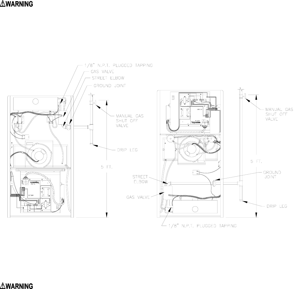
J. GENERAL GAS PIPING
: Because of the potential of odorant fade, a gas leak may not be detected by smell. If
this furnace is installed below grade, contact your gas supplier for a gas detector.
1. Left and right gas supply piping - These furnaces are set-up to be gas piped through either the left or
right side by using a street elbow and a straight pipe. For the purposes of service, it is recommended
that the gas union be located inside the furnace, when possible.
Figure 18
2. A drip leg must be used on both LP and natural gas installations prior to the furnace in order to trap
oil, condensate and other impurities which might otherwise lodge in the gas valve or plug the burner
orifice. A drip leg shall be provided at the outlet of the gas meter when there is excessive
condensation between the gas meter and the furnace. Failure to install a drip leg may void the limited
warranty on the furnace.
: All gas piping must be leak tested using a soap and water solution (when the gas is
turned on) following the procedure outlined in Section III, J, of this manual. A final test for gas
leakage must be made after purging the gas line (refer to Section IV, B, of this manual). This test
must be conducted with the unit operating and should include the furnace piping and gas valve.
Never use an open flame to check for a gas leak.
26
All installations and services must be performed by qualified service personnel.
: Care must be taken not to wet electronic components during leak test. Wetting the
primary ignition module may damage its circuitry and cause a hazardous situation. Dry moisture
from all leads and terminals if wetting occurs. Wait at least 24 hours for the circuit to fully dry
before energizing the burner circuit.
J1. REQUIREMENTS AND SIZING OF DUCT WORK
The duct system must be sized and installed by a qualified installer or service person, following the
design standards of the Air Conditioning Contractors of America (ACCA) or ASHRAE.
1. When it is located in the same room as the furnace, a return air register must be installed a minimum of
20 feet away from the furnace.
2. The return air duct shall also be sealed to the furnace and also terminate outside of the furnace space,
if supply ducts carry circulated air to areas outside the space containing the furnace.
3. The return air duct system must equal the supply air duct system in its capabilities. Use a supplier's
catalog for proper sizing of outlet and return air registers and grills to ensure that they meet the CFM
requirements of the run to which they are connected.
4. If the furnace is used in connection with an air conditioning evaporator coil, the furnace must be
installed parallel with or on the upstream side of the coil, to prevent condensation in the heat exchanger.
If the evaporator coil is installed with a parallel flow arrangement, dampers or other means to control flow
of air should be installed to prevent chilled air from entering the furnace. If such a device is manually
operated, it must be equipped with a means to prevent operation of either the furnace or air conditioner
unless it is in the full heat or cool position.
We recommend that the outlet duct be equipped with a removable access panel to allow for visual
inspection of the heat exchanger to check for leakage or to allow for insertion of a probe sampler in the
air stream. This removable access cover should be attached to ensure there is no air leakage.
5. The duct system shall be sized for the maximum CFM requirement of the installation whether it is for
heating or cooling. Two common rules for heating and cooling follow:
A. 400 CFM (1200 BTU's) per ton of cooling is required.
B. 14 CFM of heating per 1000 BTU's of furnace output based on its steady state efficiency and a 55° to
85° temperature rise.
EXAMPLE: Heating output of a furnace is 100,000 BTU/HR
100,000 BTU x 14 cfm = 1400 CFM
1000 BTU
Air conditioning installed is 4 tons x 400 CFM = 1600 CFM or 48,000 BTU’s. NOTE: The duct system
must be sized for the larger CFM requirement for cooling. If only 3 tons 36,000 BTUs of cooling x 400
CFM = 1200 CFM was installed, the duct would have to be sized for the 1400 Cfm heating requirement.
27
All installations and services must be performed by qualified service personnel.
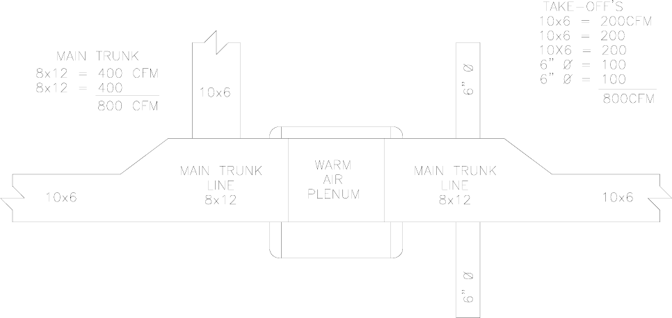
Figure 18A
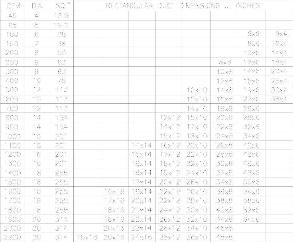
All trunk lines, take-offs, registers and grill-free areas must be figured when determining the air handling
capacity of a duct system. One can obtain the necessary duct system size by utilizing the chart below.
(For example, see Figure 18A.) Use a supplier’s catalog for proper sizing of outlet and return air registers
to insure that the register will meet the CFM requirements of the run to which it is connected.
The main trunk lines, take offs, registers and grills of the supply return air duct system must have an
adequate square inch area to move the desired CFM in order to achieve proper movement. The following
chart shows the CFM air handling capability based on a 0.1” SP loss in the supply duct system. The total
external static pressure should not exceed .2 inches water column.
28
All installations and services must be performed by qualified service personnel.
DUCT SIZES FOR HOMES, QUIET OFFICES, OR SIMILAR INSTALLATIONS
TABLE 2A
Each of the system components (trunk lines, take offs, runs and register and grill-free areas) must be
properly sized and matched together to ensure the necessary air handling capacity of a duct system. A
12" x 8" duct with a 400 CFM capacity for example will not flow 400 CFM if the register(s) to which it
connects only flow a total of 200 CFM.
The speed of the blower motor may have to be changed to obtain the proper 55°F to 85°F temperature
rise for heating when an air conditioning coil is installed. This depends on the static resistance of an
individual duct system and the size of the air conditioner.
29
All installations and services must be performed by qualified service personnel.
K. FILTERS
1. CHX3 MODELS: HIGHBOYS
It is necessary to cut the return air opening in the bottom or side casing depending upon the needs of the
specific installation.
NOTICE: If your CHX3 will require air delivery above 1800 CFM, it is advisable that both sides, a
combination of 1 side and the bottom, or the bottom only be used for return air. (If a return is cut in the
bottom, it should be as large as the return opening in the equivalent CDX3 model. (See specification
sheet in beginning of this manual).
This CHX3 furnace has been factory supplied with a high quality re-usable filter rated for air velocities up
to 600 ft/min. An optional Thermo Products filter rack assembly (part no. AOPS7547 for CHX3-75 thru
100 and AOPS7375 for CHX3-125) is available which is sized for the filter provided.
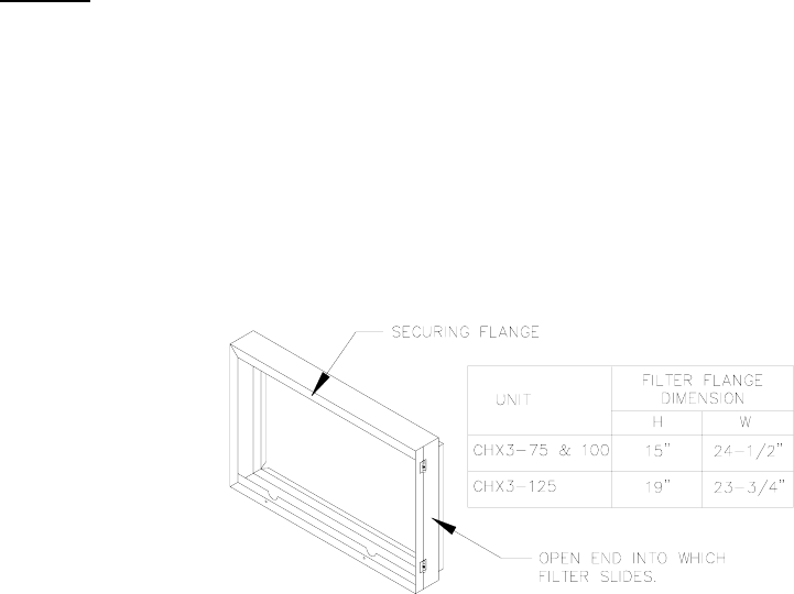
If an optional Thermo Pride filter rack AOPS7547 (figure 19) is used with the furnace, it will serve as a
template to scribe a mark for the return air opening on the casing. Place the filter rack on the casing one
inch up from the bottom of the furnace and centered from side to side. Place the securing flange against
the casing for locating the return air opening.
Figure 19
PLEASE NOTE: While scribing the return air opening, the filter rack can be held into position by tape or
similar means.
Position the open end of the filter rack so that it is accessible for filter replacement. Once the filter rack is
positioned correctly, scribe a line along the inside of the securing flange of the filter rack on three of the
sides. To scribe a line on the fourth side, on the open end, use the open end support for a guide.
Remove the filter rack and cut the return air opening in the casing. Now the filter rack can be permanently
attached to the furnace with screws or pop-rivets along the securing flange.
Connect the return plenum to the filter rack and slide the filter into place.
2. CDX3 MODELS: COUNTERFLOWS
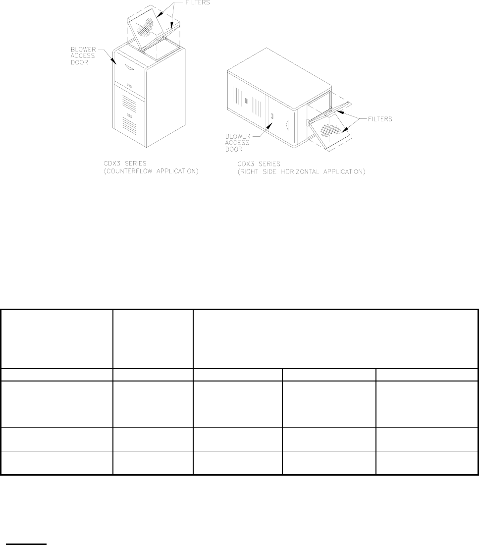
This CDX3 furnace has been factory supplied with two high quality reusable filters rated at 600 ft/min.
These filters are designed to be mounted on the return air plenum opening on the top of the furnace in
the double “vee” style rack provided (see Figure 20). If feasible, it is recommended that slits be cut in the
return front to allow for easier access of the filters.
30
All installations and services must be performed by qualified service personnel.
Figure 20
3. USE OF NON-THERMO PRIDE FILTER RETENTION MEANS
If a method other than the Thermo Pride filter rack is selected for retention of the filter and/or use of a
different filter type is desired, see Table 3 for minimum size guidelines for selecting a filter system for the
CHX3 or CDX3 furnaces.
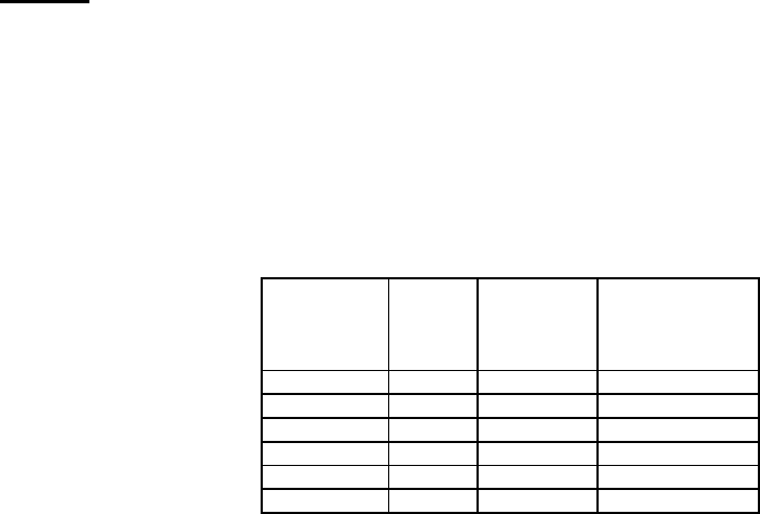
MINIMUM FILTER AREA REQUIRED (LENGTH X WIDTH, SQ. IN.)
TABLE 3
FILTER TYPE MAXIMUM
RATE
AIR VELOCITY
Required CFM / (Filter Velocity Rating x 144) = min. filter
(in2)
FURNACE MODEL
CHX3,CDX3-75 CHX3,CDX3-100 CHX3,CDX3-125
*THERMO
PRODUCTS
SUPPLIED
PERMANENT FILTER
600 FT./MIN. 254 IN.2* 328 IN.2* 402 IN.2*
STANDARD
PERMANENT FILTER 500 FT./MIN. 304 IN.2394 IN.2484 IN.2
DISPOSABLE TYPE
FILTER 300 FT./MIN. 506 IN.2656 IN.2804 IN.2
* The Thermo Products supplied filter can be cut to size to fit other filter retention systems as long as the
minimum size requirement is met. NOTICE: Any internal stiffeners used in the filter must not be removed,
although they can be cut to size as needed.
NOTICE: The filter areas in table 3 are the minimum areas required based on the CFM generated by
the furnace for standard heating speeds only. The following formula can be used to determine the
minimum filter area required for cooling if the unit is equipped with cooling. This value should then be
compared to the value shown in table 3 and the larger of the two should then be used for determining the
minimum filter area required for that installation.
31

All installations and services must be performed by qualified service personnel.
FORMULA:
(tons of cooling) x (400 CFM per ton) (144 square inches per foot) = filter area sq.inches
(max. air velocity of filter from table 3 for the filter type) = length x width of
filter in inches
EXAMPLE: If you had a CHX3-100 furnace and 4 tons of cooling and a standard permanent filter.
4 tons x 400 CFM x 144 = 460 square inches for cooling
500
For heating a CHX3-100 needs 394 square inches of filter. The filter system must be designed for the
larger CFM requirement determined for cooling of 460 square inches. A filter would have to be sized so
that the area (length X width) was at least 460 sq. in.
L. WIRING
All wiring shall be performed by a qualified electrician or service person. The wiring must comply with
local codes, the instructions in this manual, and in the absence of codes with the National Electrical Code
(ANSI/NFPA-70 or latest edition).
1. The following items are guidelines to complete the wiring portion of the installations.
a. A separate power supply circuit with over current protection and a disconnect switch must be
provided. The minimum fuse or circuit breaker size is 20 amp.
b. All CHX3 and CDX3 Series furnaces are supplied with a fuse disconnect switch box to be mounted
on the outside surface of the right or left side casing so a fuse disconnect can be mounted on the
furnace. Make the 115 volt supply connection in this junction box. A green screw and a strain relief
are provided in order to connect the power supply ground wire and provide strain relief for the 115
volt power leads from the furnace in the fuse disconnect box. A disconnect switch can be field
mounted on the 2x4 box provided. If not, the disconnect switch must be located reasonably close to
and within sight of the furnace.
NOTICE: The hot surface igniter and operation of this furnace depends on correct polarity. The hot leg of
the supply circuit must be connected to the black line lead and the common leg to the white line lead in
the field mounted junction box. The hot leg must pass through the disconnect switch in all cases to
prevent the hazard of electrical shock when servicing.
IMPORTANT: The furnace must be grounded in accordance with local codes and with the National
Electrical Code (ANSI/NFPA NO. 70 or latest edition) when an external electrical source is utilized.
2. ELECTRONIC AIR CLEANER (EAC) AND HUMIDIFIER INSTALLATION
The ignition module on this furnace has designated terminals to control the operation of an electronic air
cleaner and/or humidifier. These terminals provide line voltage (110-20VAC) for the control of these
accessories. (See Figure 21). NOTICE: It is important to confirm that the operating voltage of the
humidifier or EAC being installed matches the output of this control. If not, a field supplied relay or
transformer may be necessary to provide the proper control and supply voltage for the accessory being
installed. See the manufacturers instructions for the humidifier or EAC for additional instructions.
32
All installations and services must be performed by qualified service personnel.
3. THERMOSTAT CONNECTIONS AND ANTICIPATOR SETTING
NOTICE: For two-stage thermostat wire connectors see wire diagram page 59.
For single-stage thermostat with two-stage operation connect W from thermostat to W1 on control. W2
on control board is not used. Thermostat dip switches S7-1 & S7-2 on control board (Fig. 21) will need to
set at the desired setting per (Table 4B). In this configuration the furnace will light and burn on low fire. If
thermostat has not been satisfied in set delay time for second stage the control will step up to high fire
until thermostat is satisfied. The auto setting will allow the control to calculate the delay for second stage
based on demand. The average calculated duty cycle chart below (Table 4A) shows how the control
calculates staging based on demand.
Table 4A
Average
Calculated
Duty Cycle %
Equals
or is less
than
Low to High
Stage Delay Demand
0 38 12 Min Light
38 50 10 Min Light to Average
50 62 7 Min Average
62 75 5 Min Average to Heavy
75 88 3 Min Heavy Light
88 100 1 Min Heavy
Proper control of the indoor temperature can only be achieved if the thermostat is calibrated to the
heating and/or cooling cycle. A vital consideration of this calibration is related to the thermostat heat
anticipator.
The proper thermostat heat anticipator setting is 0.4 AMPS for furnace operation only. To increase length
of cycle, increase setting of heat scale; to decrease length of cycle, decrease setting of heat scale.
Anticipators for the cooling operation are generally pre-set by the thermostat manufacturer and require no
adjustment.
Anticipators for the heating operation are of two types, pre-set and adjustable. Those that are pre-set will
not have an adjustment scale and are generally marked accordingly.
33
All installations and services must be performed by qualified service personnel.
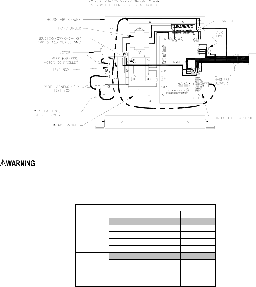
4. BLOWER AND CONTROL PANEL WIRING
Figure 21
: TURN OFF THE ELECTRICAL POWER to the furnace before attempting to
disconnect blower wiring.
Table 4B
Options
S7-1 S7-2 Time
Off Off Off *
On Off 10 Min
Off On Auto
On On 20 Min
S7-3 S7-4 Time
Off Off 90 Sec
Off On 120 Sec *
On Off 150 Sec
On On 180 Sec
S7 DIP Switch
Heat Fan
Off Delay
* Factory Setting / 2 Stage Thermostat setting
Thermostat
Type and
W2 Delay
Switch Settings
34

All installations and services must be performed by qualified service personnel.
Modifications to ECM blower speed settings are done using the S3 and S4 dip switch controls. Thermo
Pride two-stage furnaces are factory shipped at the CFM settings listed below in Table 4C.
2-Stage Blower Settings (from factory)
Table 4C
Unit Control Board
Dip Switch
Settings
Heating
CFM
(low fire)
Heating
CFM
(high fire)
Constant Fan
CFM Cooling
CFM
CDX3-75 SW3 1-4 Off
SW4 1-3 Off
SW4 4 On 885 1012 500 1000
CHX3-75 SW3 1-4 Off
SW4 1-4 Off 760 931 500 1000
CDX3-100 SW3 1-4 Off
SW4 1-3 Off
SW4 4 On 1094 1340 600 1200
CHX3-100 SW3 1-4 Off
SW4 1-4 Off 1015 1243 600 1200
CDX3-125 SW3 1-4 Off
SW4 1-3 Off
SW4 4 On 1366 1673 700 1400
CHX3-125 SW3 1-4 Off
SW4 1-4 Off 1270 1556 700 1400
For adjustments to the Cooling CFM settings, as well as all additional CFM changes, please reference
the dip switch tables listed in the ECM operation manual. (Included with every furnace.)
5. DE-HUMIDIFICATION
The ECM motor in conjunction with the W/R 50V51-843 has a feature to enhance de-humidification in the
cooling mode. In the dehumidify mode the indoor blower motor (ECM) reduces CFM. By reducing airflow
the indoor coil runs colder and thus extracts more moisture from the air.
The W/R 50V51-843 is shipped from the factory with dipswitch S5-2 set to on for system that do not have
a dehumidification connection from the thermostat. For systems using a thermostat that provides
dehumidification option move dip switch S5-2 to “OFF”. With the S5-2 switch in the “OFF” position the air
conditioning fan speed will be reduced 30% from the normal CFM setting when the humidity in the home
is higher than the set point of the dehumidistat.
6. FIELD WIRING AND REPLACING WIRING
Field wiring between the furnace and devices not attached to the furnace shall conform with the
temperature limitation for Type T wire[63°F rise (35°C)] when installed in accordance with the
manufacturer’s instructions. If any of the original factory supplied furnace wiring is replaced or a separate
device other than the thermostat is wired internal to the unit 105°C thermoplastic or equivalent wire must
be used.
35
All installations and services must be performed by qualified service personnel.
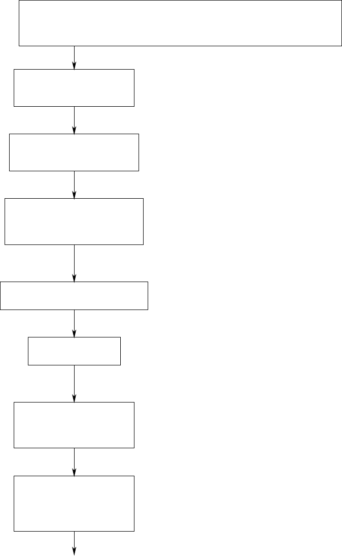
CONTINUOUS SAFE OPERATION CHECK
IF FLAME SIMULATION CONDITION PRESENT OR ROLL-OUT SWITCH
OPENS, SYSTEM ENERGIZES INDUCER FAN FOR 15 SECONDS AND
CIRCULATOR BLOWER AT HEATING SPEED UNTIL SITUATION CORRECTION
AT ANY TIME THE
GAS VALVE IS
NOT ENERGIZED
A. SEQUENCE OF OPERATIONS
THERMOSTAT CALLS FOR
HEAT W1 OR W1 & W2,
CONTACTS CLOSE
LOW FIRE PRESSURE
SWITCHES SENSES ADEQUATE
DIFFERENTIAL PRESSURE,
CONTACTS CLOSE
IV. STARTING THE UNIT
INDUCER REDUCES
TO LOW SPEED
LOW PRESSURE SWITCH
SENSES ADEQUATE
PRESSURE DIFFERENTIAL,
CONTACTS STAY CLOSED
50V51-843 CONTROL
ENERGIZED, INDUCER
ENERGIZED ON HIGH SPEED
PREPURGE IGNITION DELAY,
INDUCER RUNS FOR 15 SECONDS
POWER IS APPLIED TO
THE WHITE RODGERS
SILICON NITRIDE IGNITOR.
IGNITOR WARM-UP IS
17 SECONDS
36
All installations and services must be performed by qualified service personnel.
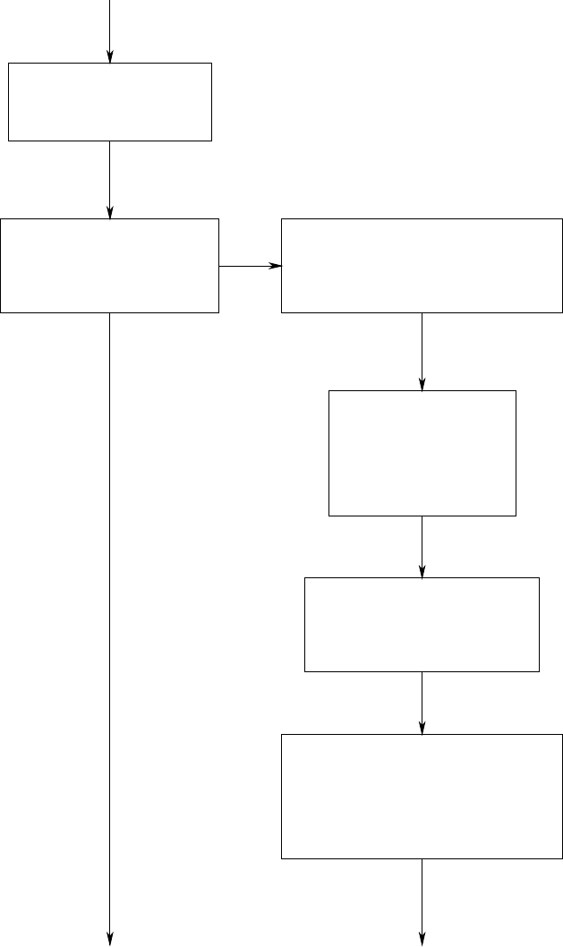
FLAME MUST BE DETECTED
WITHIN 4 SECONDS IF
FLAME IS DETECTED, THE
DELAY-TO-FAN-ON TIME
BEGINS (45 SECONDS)
THE RETRY SEQUENCE
PROVIDES A 60 SECOND
WAIT BEFORE IGNITION
RETRY. RETRY IS
ATTEMPTED WITH A
DIFFERENT VOLTAGE
SETTING.
IF NOT
IF SO
AFTER IGNITOR WARM-UP,
THE 36J54 GAS VALVE IS
ENERGIZED TO OPEN ON
LOW FIRE SETTING
IF FLAME IS NOT DETECTED, THE
GAS VALVE IS DE-ENERGIZED,
THE IGNITOR IS TURNED OFF AND
THE 50V51-843 CONTROL GOES
INTO "RETRY" SEQUENCE
IF IGNITION ATTEMPT IS
UNSUCCESSFUL, ONE MORE
RETRY WILL BE MADE
BEFORE THE 50V51-843
GOES INTO SYSTEM LOCKOUT
IF FLAME IS DETECTED, THEN LOST,
THE 50V51-843 WILL REPEAT THE
INITIAL IGNITION SEQUENCE FOR A
TOTAL OF TEN RECYCLES. AFTER
TEN UNSUCCESSFUL RECYCLE
ATTEMPTS, THE CONTROL WILL
GO INTO SYSTEM LOCKOUT.
37
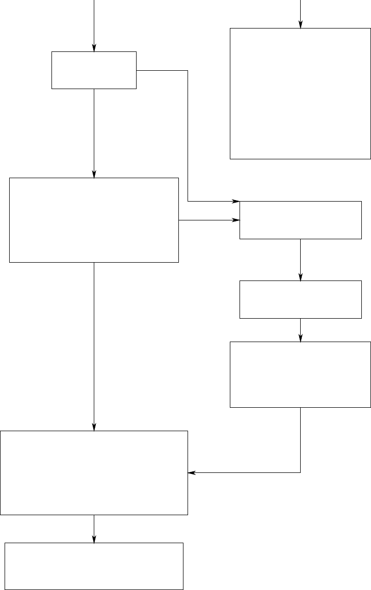
All installations and services must be performed by qualified service personnel.
IF SYSTEM IS IN LOCKOUT,
THE MODULE WILL RESET
ITSELF AFTER 60 MINUTES
OR MAY BE MANUALLY
RESET BY INTERRUPTING
THE POWER TO THE FURNACE
AT THE DISCONNECT OR
INTERRUPTING THE CALL FOR
HEAT AT THE THERMOSTAT.
IF THIS DOES NOT RESTART
THE SYSTEM, REFER TO THE
TROUBLESHOOTING SECTION
OF THIS MANUAL.
AFTER THE DELAY-TO-FAN-OFF
PERIOD ENDS, THE CIRCULATING
AIR FAN AND (OPTIONAL) ELECTRONIC
AIR CLEANER ARE DE-ENERGIZED.
AFTER DELAY-TO-FAN-ON PERIOD
ENDS (45 SECONDS), CIRCULATING
AIR FAN IS ENERGIZED AT LOW
FIRE HEATING SPEED OR HIGH
FIRE IF W2 IS ENERGIZED. THE
(OPTIONAL) ELECTRONIC AIR
CLEANER AND HUMIDIFIER
ARE ENERGIZED.
IF THERMOSTAT
W2 CONTACTS
ARE CLOSED
OTHERWISE
CALL
FOR
HIGH
FIRE
NO CALL
FOR
HIGH FIRE
THERMOSTAT CLOSES W2
CALLING FOR HIGH FIRE
HEATING.
GAS VALVE, INDUCER AND
AIR FAN ARE ENERGIZED
TO HIGH FIRE SETTINGS
WHEN THERMOSTAT W1 IS SATISFIED,
CONTACTS OPEN AND THE GAS
VALVE IS DE-ENERGIZED. AFTER
PROOF OF FLAME LOSS, INDUCER
STARTS 5 SECOND POST PURGE
AND (OPTIONAL) HUMIDIFIER IS
DE-ENERGIZED. THE DELAY-TO-
FAN-OFF PERIOD BEGINS (120 SECONDS)
WHEN THERMOSTAT HAS
SATISFIED W2, CONTACTS
OPEN AND THE GAS VALVE
AND AIR FAN HIGH FIRE
SETTINGS ARE DE-ENERGIZED
AFTER 30 SECOND DELAY.
38
All installations and services must be performed by qualified service personnel.
B. INITIAL START UP:
This furnace does not have a pilot. It is equipped with a hot surface igniter, which automatically lights the
burner. Do not attempt to light the burner by hand. Check the following items before the initial start-up.
1. Check all wiring for loose connections and proper hook up.
2. Leak test gas piping connections.
3. Check all tubing to the pressure switch and drains to make sure they are connected firmly at all their
connection points.
4. Check flue pipe, combustion air inlet and all PVC connections for tightness and to make sure there is
no blockage.
5. Make sure air filter is in place.
6. Make sure the outside vent and air intakes are installed according to instructions and that they are
free from blockage.
7. Make sure that the drain trap is properly connected to the furnace and to the buildings drain system.
OPERATING INSTRUCTIONS:
: Turn off power to furnace before it is placed into service. The gas piping system
must have been leak tested by a qualified heating contractor. (See Section III, J, of these
instructions on the installation of gas piping).
: It may be necessary to purge the air out of the gas line for initial start-up of the
furnace after installation. This should be done by a qualified heating contractor. If excessive gas
escapes when purging the gas supply at the union, allow the area to ventilate for at least 15
minutes before attempting to start the furnace. LP gas is especially dangerous because the
specific gravity of LP gas allows it to accumulate at floor level at a dangerous concentration. For
remainder of operating instructions, reference Users Information Manual.
: Heat exchanger oil will burn off on initial firing creating an unpleasant odor. To
prevent this odor from occurring more than once, it is suggested that:
1. A window(s) be opened.
2. The thermostat be set at highest setting.
3. The furnace remain running at conditions 1&2 for 30 minutes or until odor has dissipated.
39
All installations and services must be performed by qualified service personnel.
C. Measuring And Adjusting Heat Input Rate
DO NOT exceed input rating stamped on furnace nameplate or manufacturer's
recommended burner manifold pressure for orifice size used.
Observe the following precautions when measuring:
A. Burner manifold pressure with a pressure gauge.
1. Close the gas valve (turn the gas control knob to the OFF position) BEFORE removing the:
a. burner manifold pressure tap plug to connect the manometer (or calibrated pressure
gauge)
b. manometer, or gauge, and replacing the pressure tap plug.
2. Shut off the gas supply at the appliance service (manual gas shutoff) valve (or for LP
gases, shut off the gas at the storage tank service valve) BEFORE removing the:
a. gas valve inlet pressure tap plug
b. manometer, or gauge and replacing the inlet pressure tap plug.
3. Perform a gas leakage test at the gas valve inlet and burner manifold pressure tap plugs.
B. Gas flowrate by clocking gas meter.
1. To determine the amount of flow, through the gas meter, due to the operation of the
furnace.
a. Turn off all other appliances and extinguish their pilot flames, if equipped, or
b. Deduct the gas consumption of all other operating appliances from the total meter
reading.
2. Convert the gas flowrate to the heat input rate (in BTUH) as described in step 10 (in the
following section) and compare the value to the heat input rating on the furnace
nameplate.
40
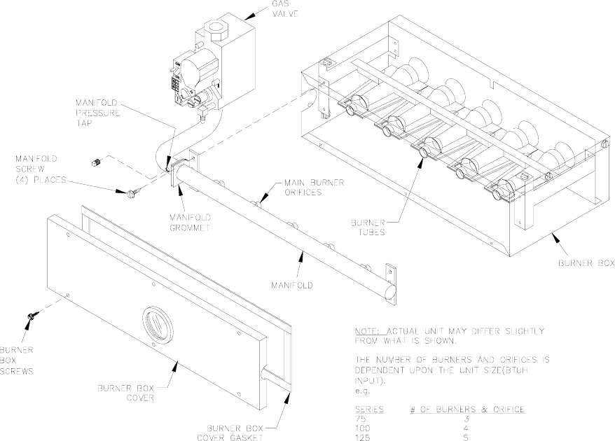
All installations and services must be performed by qualified service personnel.
NOTICE: A U-tube manometer, measuring pressure in inches of water column, is recommended
for all gas pressure measurements. However, an aneroid pressure gauge, in good working
condition, capable of reading pressure changes of 0.05 in. W.G., or less, that was recently
calibrated (within the last year), is a satisfactory alternate. These two (2) devices will be
considered as equivalent and interchangeable. Either device is referred to below as a “pressure
gauge”
NOTICE: This 2-stage gas valve has two separate gas pressure regulators. Checks and
adjustments must be made at both high fire (high adjustment) and low fire (low adjustment).
1. Shut off the gas at the automatic gas control valve (turn gas control switch to the OFF position).
2. Remove the outlet pressure tap plug from gas burner manifold and connect a pressure gauge.
Refer to Figure 22, below.
Figure 22: Exploded View of CDX/CHX Gas Control System
3. Turn on the gas at the automatic gas control valve (turn gas control switch to the ON position).
4. Adjust the room thermostat so the furnace will operate on low fire only.
41

All installations and services must be performed by qualified service personnel.
5. To obtain an accurate manifold gas pressure reading, the main burner must be cycled on and off
several times to stabilize the gas control valve pressure regulator diaphragm.
6. Allow the burner to operate for at least 3 minutes before taking gas pressure readings.
7. Using a pressure gauge, measure the burner manifold gas pressure.
8. If checking the input rate by measuring burner manifold pressure, skip to step 12. If
measuring the input rate using a gas meter, proceed to step 9.
9. Using a clock (or watch) capable of measuring time in seconds, carefully clock the gas meter to
determine the time for one (1) complete revolution of the gas meter dial or reel. At least one (1)
cubic foot of gas flow should be measured. Use Table 6 to determine the main burner gas flow
rate in cubic feet per hour (CFH).
NOTICE: Some gas meters will require more than one (1) cubic foot of gas pass through the
meter for reasons of accuracy. When more than one (1) cubic foot of gas is consumed, divide
the total time by the number of cubic feet for comparison to the figures in Table 6.
10. Compare actual heat input rate with our recommended input (printed on the furnace rating label).
To convert the rating label input rate (given in BTUH) to the equivalent gas flowrate (in CFH), use
the following formula:
()
CFHinflowrategasFuel
ft
BTU
invalueheatinghighergasFuel
B
TU
H
inrateinputHeat
×
⎟
⎟
⎠
⎞
⎜
⎜
⎝
⎛
=
3
)(
or,
()
⎟
⎟
⎠
⎞
⎜
⎜
⎝
⎛
=
3
)(
ft
BTU
invalueheatinghighergasFuel
BTUHinrateinputHeat
CFHinflowrategasFuel
11. If the measured input rate is above, or below, the rating label value by more than 2%, adjust the
manifold gas pressure using the gas control valve pressure regulator to obtain the input rating
within a ± 2% range. Refer to steps 12(a) through 12(d).
12. If the gas pressure is not within the specified low fire manifold pressure range (refer to
Table 5), use the following procedure to adjust the low fire, gas pressure regulator to match the
specified low fire manifold pressure.
a. Remove the regulator cover screw from the gas valve. Refer to Figure 23.
42
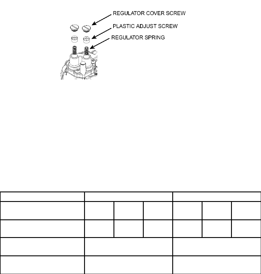
All installations and services must be performed by qualified service personnel.
Figure 23:
b. Turn the inner plastic adjustment screw clockwise to increase, or counterclockwise to
decrease, the gas pressure (and gas flow) to the main burner.
c. Replace the regulator cover screw and tighten it firmly to prevent gas leakage.
d. Referring to Table 5, measure the gas pressure and to confirm it has been adjusted to within
the allowable range. Repeat adjustments (a) through (c), as required.
Table 5 Design Gas Pressures for each Furnace Model Series,
Operating Mode, and Type of Fuel.
Fuel Gas Type Propane Natural
Operating Mode and
Model Series High Fire CHX Low
Fire CDX Low
Fire High Fire CHX Low
Fire CDX Low
Fire
Normal Manifold
Pressure (in. W.G.) 10.0 ± 0.3 4.8 ± 0.3 5.6 ± 0.3 3.5 ± 0.3 1.8 ± 0.3 2.0 ± 0.3
Maximum Gas Supply
Pressure (in. W.G.) 14.0 14.0
Minimum Gas Supply
Pressure (in. W.G.) 11.0 4.5
13. Adjust the room thermostat so the burner will operate on high fire only.
14. To obtain an accurate manifold gas pressure reading, the main burner must be cycled on and off
several times to stabilize the gas control valve pressure regulator diaphragm.
15. Allow the burner to operate for at least 3 minutes before taking gas pressure readings.
16. Using a pressure gauge, measure the burner manifold gas pressure.
17. If checking the input rate by measuring burner manifold pressure, proceed to step 18. If
measuring the input rate by clocking the gas meter, repeat steps 9 through 11, above.
43

All installations and services must be performed by qualified service personnel.
18. If the gas pressure is not within the specified high fire manifold pressure range (refer to
Table 5), repeat steps 12(a) through 12(d), above, adjusting the high fire gas pressure regulator.
If the manifold pressure remains low and it cannot be adjusted into the proper range, the supply
pressure may be too low. Follow these steps.
a. Turn off the gas at the manual gas shutoff valve.
b. Remove the automatic gas control valve inlet pressure tap and attach another pressure
gauge to the inlet tap.
c. Turn on the gas and repeat steps 14 and 15, above.
d. Adjust the upstream (inlet) gas pressure to 14.0 in. W.G., or as close as possible.
e. Using a pressure gauge, measure and adjust the burner manifold gas pressure.
If it is still not possible increase the manifold gas pressure to within the required range, there
is too little gas supply to operate the furnace at full (high fire) input rate under present
conditions. If necessary, consult your gas supplier or qualified heating contractor for
recommendations to alleviate the problem.
19. Turn off the gas at the manual gas shutoff valve (turn handle to the OFF position).
20. Remove all pressure gauges and replace all pressure tap plugs.
21. Go to Checkout Procedure below.
Adjusting Burner Input For Altitudes Above 2000 Feet
Ratings of gas utilization equipment are based on sea level operation and shall not be changed for
operation at elevations up to 2,000 feet (600 m.). For operation at elevations above 2,000 feet
(600 m), equipment ratings shall be reduced at the rate of 4 percent for each 1,000 feet (300 m)
above sea level.
For additional information, refer to the latest edition of the National Fuel Gas Code.
Checking The Burner Flame
c CAUTION: The furnace model series CDX3 and CHX3 are sealed combustion designs that do
not require an air shutter adjustment (air shutters are not used) for proper flame characteristics. The
burner box access cover must always be secured with all screws in place and tightened before
operating furnace.
Once the input rate has been confirmed correct for a specific application, the burner flames should be
checked for proper adjustment.
44
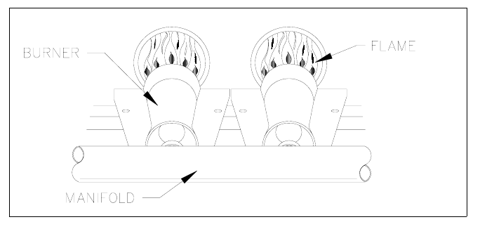
All installations and services must be performed by qualified service personnel.
This furnace is designed not to require any burner adjustment. Burner aeration is fixed in this design.
Burner flames can be seen by looking through the sight glass located on the burner box. Burner
flames should be well-defined, light to medium blue in color, and almost transparent. (refer to Figure
24).
Figure 24: Sketch of Typical Main Burner Flames During Operation
NOTICE: When operating on propane gas, it is not unusual for flames to have yellow or orange
colored tips.
If combustion problems are evident, it may indicate problems with either the furnace air supply or the
vent system. Refer to the installation and maintenance sections of this manual, or contact Thermo
Products at (574) 896-2133.
Checkout Procedure
1. Confirm the furnace exhaust vent and combustion air intake are constructed as outlined in the
installation and service manual. They must not be blocked or otherwise obstructed.
2. Place system in operation and observe at least one (1) complete cycle to ensure all controls are
operating properly. The main burner must light reliably under all conditions.
3. Perform gas leakage test on all gas pipe connections and pressure tap plugs.
45

All installations and services must be performed by qualified service personnel.
TIME (sec.) FLOW (cfh) TABLE 6 - CONVERTING GAS FLOW RATE
40 90
41 88 * For one cubic foot per revolution gas meter dials,
42 86 use Table directly.
44 82
45 80 * For 1/2 cubic foot per revolution gas meter dials:
46 78 1. Determine time for two dial revolutions
47 77 2. Use Table directly
48 75
49 73 * For two cubic foot per revolution gas meter dials:
50 72 1. Determine time for one complete dial revolutions
51 71 2. Divide time by two
52 69 3. Use Table directly
53 68
54 67
55 65
56 64
57 63
58 62
59 61
60 60
62 58
64 56
66 54
68 53
70 51
72 50
74 49
76 47
78 46
80 45
84 43
88 41
92 39
96 38
100 36
105 34
110 33
115 31
120 30
125 29
130 28
135 27
140 26
150 24
160 23
170 21
180 20
46

All installations and services must be performed by qualified service personnel.
D. FURNACE CHECKOUT PROCEDURE
Before any system of gas piping is finally put into service, it shall be carefully tested to assure that it is
gas tight as indicated in the manual.
NOTICE: All controls on the unit should be checked for proper functioning prior to the qualified service
personnel leaving the job site. Specifically the following should be checked:
With furnace in normal heating operation, check to make certain blower will start and stop automatically
under control of integrated fan control.
1. Check safety limit control as follows:
a. Shut off incoming power.
b. Disconnect blower motor leads.
c. Restore power to furnace.
d. Set thermostat above room temperature calling for heat.
e. When temperatures are reached in furnace at limit control setting with blower out of
operation, burner should shut off.
f. Shut off electrical power.
IMPORTANT: Remove blockage or reconnect blower motor and restore power.
2. Make certain thermostat will automatically start and stop furnace.
3. Block the flue pipe gradually with a flat piece of metal, until the pressure switch functions shutting off
the main burners. Note: If the burner was initially operating in high fire, the burner will first reduce
rate to the low fire setting. As the flue becomes more blocked, the pressure switch will function and
completely shut off the main burners.
4. Block the PVC pipe inlet gradually with a flat piece of metal until pressure switch functions shutting off
the main burners. Note: If the burner was initially operating in high fire, the burner will first reduce
rate to the low fire setting. As the flue becomes more blocked, the pressure switch will function and
completely shut off the main burners.
IMPORTANT: Remove flue air inlet blockage when done.
5. Remove the blower compartment access door with the furnace operating. The door interrupt switch is
in the 120 volt circuit and will shut down the entire system. Replace the blower door and the furnace
start-up cycle will begin.
V. INSTALLER'S INSTRUCTIONS TO USER:
After completing the installation, the installer shall inform and/or demonstrate to the homeowner:
1. The location of all the instructions in the furnace and that these instructions and the users information
manual must be kept along with instructions for any accessories in the plastic pouch on the inside of
the furnace.
2. The location and use of the manual gas shut off valve and furnace electrical disconnect switch.
Instruct user to always shut off gas before shutting off electric power.
3. The sequence of operation of the furnace.
4. The correct operation and maintenance of the appliance as outlined in the users information manual.
47
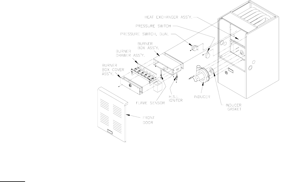
All installations and services must be performed by qualified service personnel.
5. That failure to maintain and operate this furnace in accordance with these instructions could result in
hazardous conditions, bodily injury, property damage and may void the limited warranty on the
furnace.
6. Review with and encourage the user to read the label reproductions and all warnings and instructions
outlined on the front cover and in sections I, II and III of this manual and in the Users Information
Manual.
7. Recommend that the user have a qualified heating contractor inspect the furnace at the start of each
heating season. Inform the user of the frequency of inspection required for reach item in Section III of
the Users Manual.
Figure 25
VI. TROUBLESHOOTING
NOTICE: BEFORE TROUBLESHOOTING, FAMILIARIZE YOURSELF WITH THE START UP AND
CHECKOUT PROCEDURE.
ALL INSTALLATION AND SERVICES MUST BE PERFORMED BY QUALIFIED HEATING
CONTRACTORS.
To assist you in troubleshooting this furnace, it is equipped with an integrated ignition control with
diagnostics. These diagnostics evaluate what control system has experienced a failure and will activate a
flashing light on the control in different sequences to help pinpoint the failure which has occurred.
For your convenience, Thermo Products has installed a sight glass in the blower door of this furnace. The
number of flashes in groups should be observed through this sight glass and recorded before turning off
power to the furnace. Turning off power to the furnace or removing the blower door which is equipped
with a door interlock switch will reset the control. Should this occur, use the fault code retrieval process as
described below.
To retrieve fault codes, push and release the “LAST ERROR” button for more than 1/5 second and less
than 5 seconds. (Control will indicate this period by solid GREEN for 1/5 second to 5 seconds.) The LED
will flash up to five stored fault codes, beginning with the most recent. If there are no fault codes in
48

All installations and services must be performed by qualified service personnel.
memory, the LED will flash two green flashes. The control will flash the most recent error first and the
oldest error last (last in first out). There will be 2 seconds between codes. Solid LED error codes will not
be displayed.
DIAGNOSTIC FEATURES
The 50V51 control used on this furnace continuously monitors its operation and the operation of the
system.
If the sensed failure is in the system (external to the control), the red LED will flash in the following flash-
pause sequences to indicate failure status (each flash will last approximately 0.25 seconds, and each
pause will last approximately 2 seconds):
Red LED Flash (DS1)
1 - flame sensed when no flame should be present
2 - pressure switch stuck closed / inducer error
3 - 1st stage pressure switch stuck open / inducer error
4 - open limit switch
5 - open rollout / aux limit
6 - pressure switch cycle lockout
7 - external lockout (retries)
8 - external lockout (recycles)
9 - grounding or reversed polarity
10 - gas flow with no call for heat
11 - limit switch open – blower failure
12 - ignitor failure
Solid - internal GV error, micro, and frequency check
3 double - 2nd stage pressure switch stuck open / inducer error
The LED will also flash once at power-up.
Amber LED Flash (DS1)
1 – normal call for first stage heat
2 – normal call for second stage heat
3 – W2 present with no W1
4 – Y present with no G call
Rapid – low flame sense current
Green LED indicator (DS2) is present to obtain an estimate of the air flow rate (in CFM) produced by the
house air blower. This LED cycles regularly by providing a constant light, followed by a sequence of
flashes. Each flash can be translated to programmed CFM by using the following:
1 flash per 100(programmed) CFM
: Power must be disconnected before servicing.
49
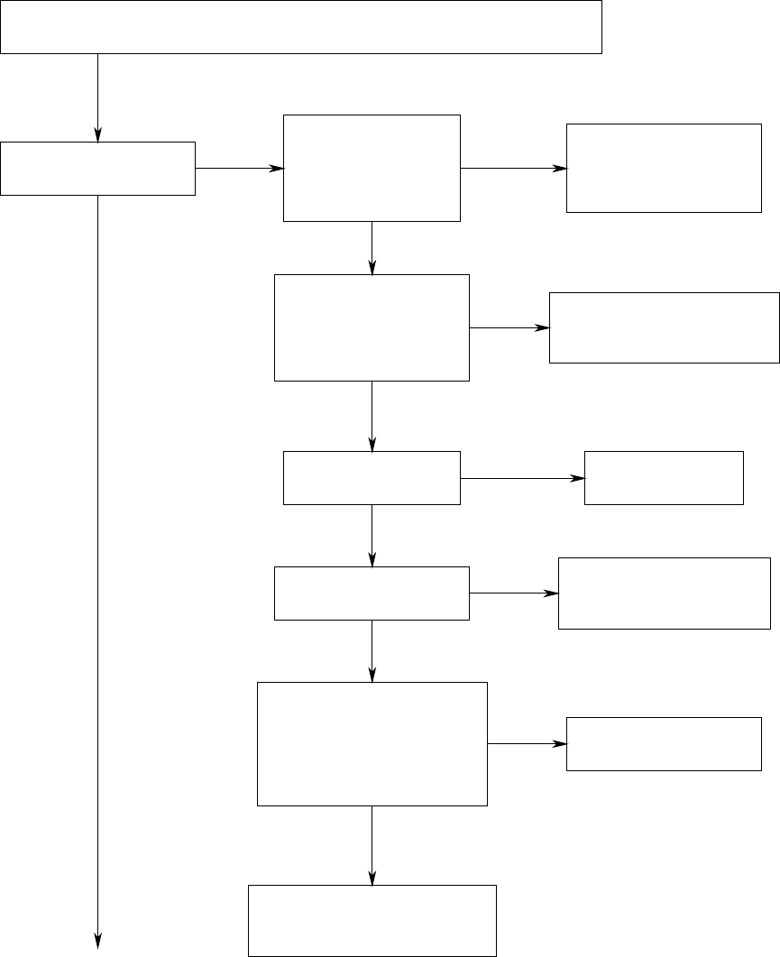
All installations and services must be performed by qualified service personnel.
SET THERMOSTAT TO CALL FOR HEAT
(MAKE CERTAIN ROOM TEMPERATURE IS BELOW THERMOSTAT SETTING)
CHECK INPUT POWER,
DOOR INTERLOCK,
SERVICE SWITCH
AND FUSES
IS THE INDUCER
BLOWER OPERATING?
CHECK 115 VOLT
CONNECTIONS. IF OK,
REPLACE TRANSFORMER
YES
NO
YES
YES
NONO
IS THERE 24V
ACROSS R AND B/C NO
IS THERE 24 VOLTS
ACROSS "R" AND "W1"?
CHECK WIRING TO
THERMOSTAT. IF OK,
REPLACE THERMOSTAT.
YES
NO
CHECK WIRING TO INDUCER
AND IF OK, REPLACE
INDUCER ASSEMBLY.
YES
YES
NO
TROUBLESHOOTING GUIDE
THE SYSTEM IS STARTED BY SETTING THE THERMOSTAT TO CALL FOR
HEAT. THE FOLLOWING SHOULD HELP ESTABLISH THE TYPE OF
MALFUNCTION OR DEVIATION FROM THE NORMAL OPERATION.
NOTE: REFER TO PAGE 48 FOR DEFINITION OF DIAGNOSTIC LEDS.
TO USE THIS DIAGRAM, YOU JUST NEED TO FOLLOW THE INSTRUCTIONS IN THE BOXES.
IS THERE 120 VOLTS
ACROSS "L1" AND
"NEUTRAL" AT THE
50V51-843 CONTROL
MODULE?
IS THERE 24 VOLTS
ACROSS "TH" & "TR"
AT THE INTEGRATED
CONTROL MODEL
50V51-843?
CHECK FUSE ON
W/R 50V51-843
IS THERE LINE VOLTAGE
ACROSS INDUCER POWER
TERMINALS "IND HI" TO
"IND N" OR "IND LO" TO
"IND N" AT THE 50V51-843
CONTROL?
REPLACE THE
50V51-843 CONTROL.
50
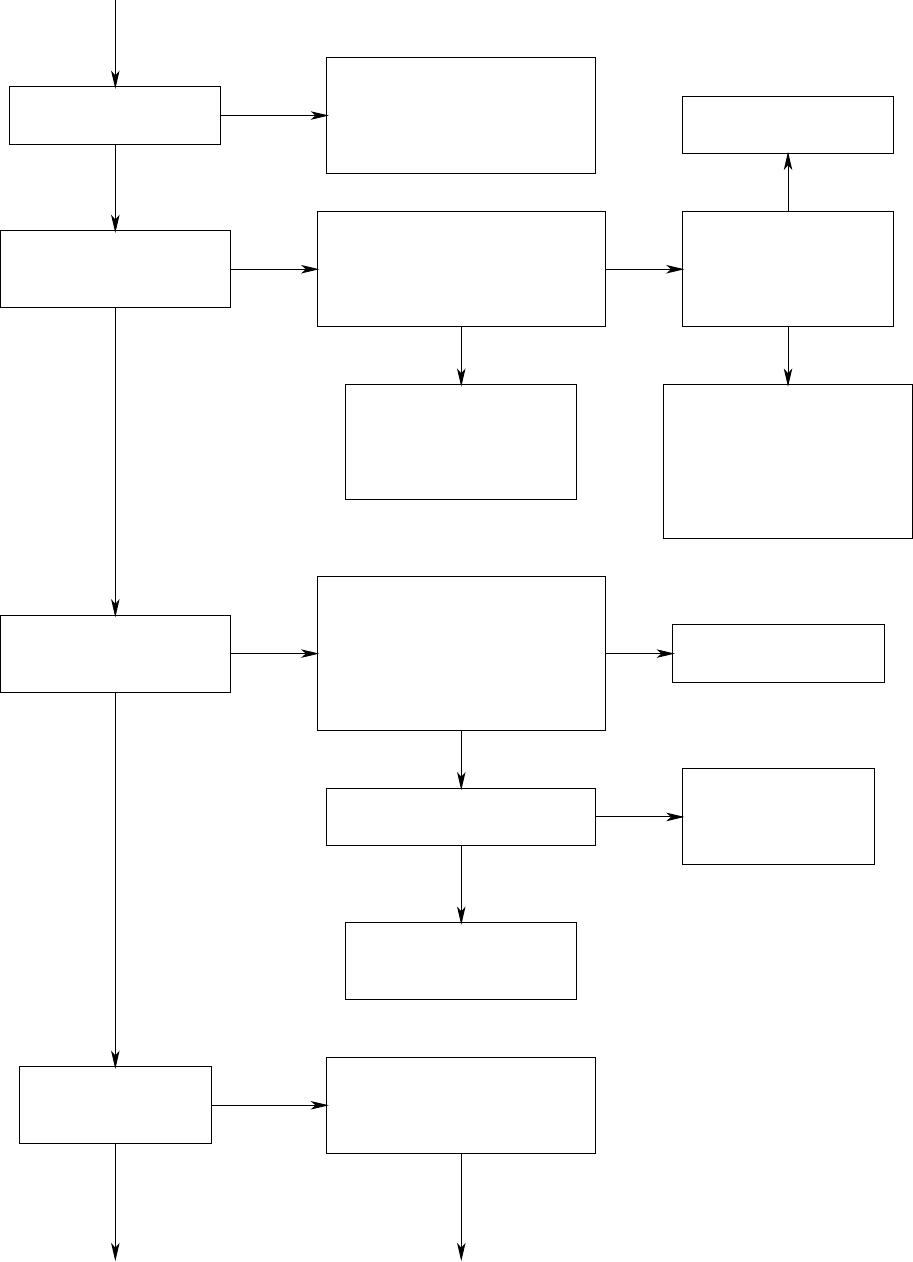
All installations and services must be performed by qualified service personnel.
IS INDUCER RUNNING
ON LOW SPEED?
DOES THE HOT
SURFACE IGNITOR
ENERGIZE AND GLOW?
CHECK WIRING TO HOT
SURFACE IGNITOR AND
IF OK, REPLACE HOT
SURFACE IGNITOR
ASSEMBLY
AFTER HOT SURFACE
IGNITOR WARM-UP,
DOES GAS VALVE OPEN?
NO
NONO
NO
YES
YES
YES
CHECK CONTACTS ON LOW
FIRE PRESSURE SWITCH
AND FOR BLOCKAGE IN FLUE.
IF OK, REPLACE DUAL
PRESSURE SWITCH.
IS THE HIGH LIMIT,
ROLL-OUT LIMIT, AND
AUX LIMIT ON
(CDX MODELS)
SWITCHES CLOSED?
NO
YES
YES
IF HIGH LIMIT OR
AUX LIMIT OPEN CHECK
FOR RESTRICTED
FILTERS OR DUCT WORK
IF ROLL-OUT SWITCH
OPEN INSPECT FLUE FOR
RESTRICTIONS.
NO
CHECK WIRING TO GAS
VALVE AND IF OK,
REPLACE GAS VALVE.
IS COLLECTOR BOX
PRESSURE SWITCH CLOSED?
YES
YES
CHECK DRAIN FOR
BLOCKAGE WATER
TRAPPED IN HOSE,
REPLACE SWITCH.
NO
NO
AFTER GAS VALVE
OPENS, DO THE
BURNERS IGNITE?
YES OK
CHECK FOR PROPER LINE
AND MANIFOLD PRESSURE.
REFERENCE GAS PRESSURE
CHART PAGE 31.
IS THERE VOLTAGE ACROSS
HOT SURFACE IGNITOR
TERMINALS "IGN" & "IGN N"
AT THE 50V51-843 CONTROL
AFTER 17 SECOND PREPURGE?
REPLACE THE
50V51-843 CONTROL.
CHECK ACROSS "MVL" AND
"MV COM" TERMINALS ON
50V51-843 CONTROL FOR 24
VOLTS DURING THE 4 SECOND
FLAME PROVING PERIOD
AFTER IGNITOR WARM-UP.
IS THERE 24 VOLTS?
REPLACE THE
50V51-843 CONTROL.
51
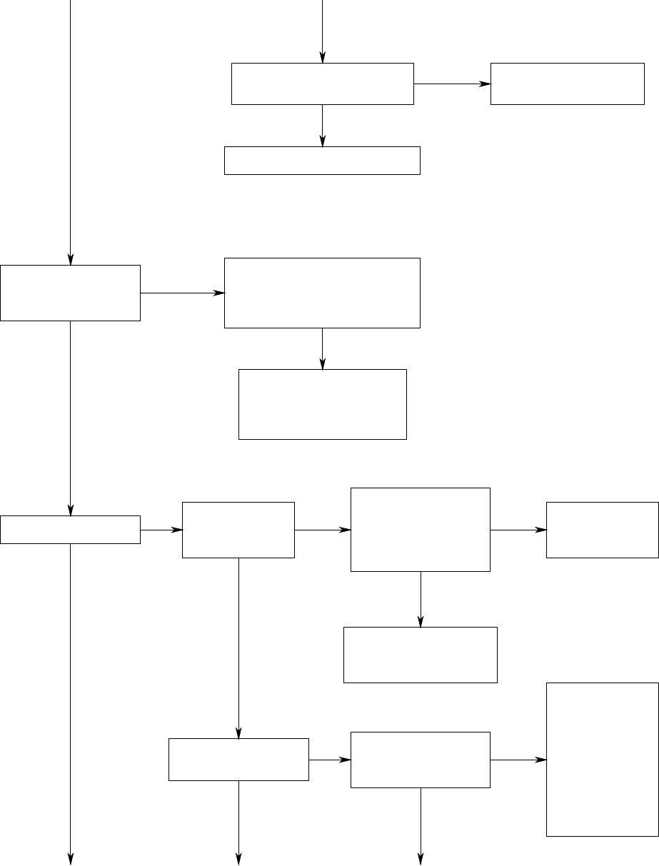
All installations and services must be performed by qualified service personnel.
IS IGNITOR
POSITIONED CORRECTLY? REPOSITION TO
CORRECT LOCATION
CHECK AND CLEAN BURNERS
DO BURNERS STAY
LIT PAST PROOF OF
FLAME CHECK?
IS W2 ENERGIZED? DOES INDUCER
GO TO
HIGH SPEED?
IS THERE LINE
VOLTAGE ACROSS
INDUCER POWER
TERMINALS "IND HI"
TO "IND N"?
REPLACE
THE 50V61-143
CONTROL.
CHECK CONNECTIONS
TO INDUCER. IF OK,
REPLACE INDUCER.
DOES BURNER
STEP TO HIGH FIRE?
IS THE HIGH FIRE
PRESSURE SWITCH
CLOSED?
YES
NO
YES
NO
NO NO
YES
YES
YES
YES YES
NONO
NO
OK
CHECK FLAME PROB2
AND WIRE AND CHECK
POLARITY ON INCOMING
POWER AND GROUND
CHECK
CONTACTS
IN HIGH
FIRE SWITCH
AND FOR
BLOCKAGE IN
FLUE. IF OK,
REPLACE DUAL
PRESSURE
SWITCH.
CHECK FOR PROPER LINE
AND MANIFOLD PRESSURE
REFERENCE GAS
PRESSURE CHART PAGE 31.
52
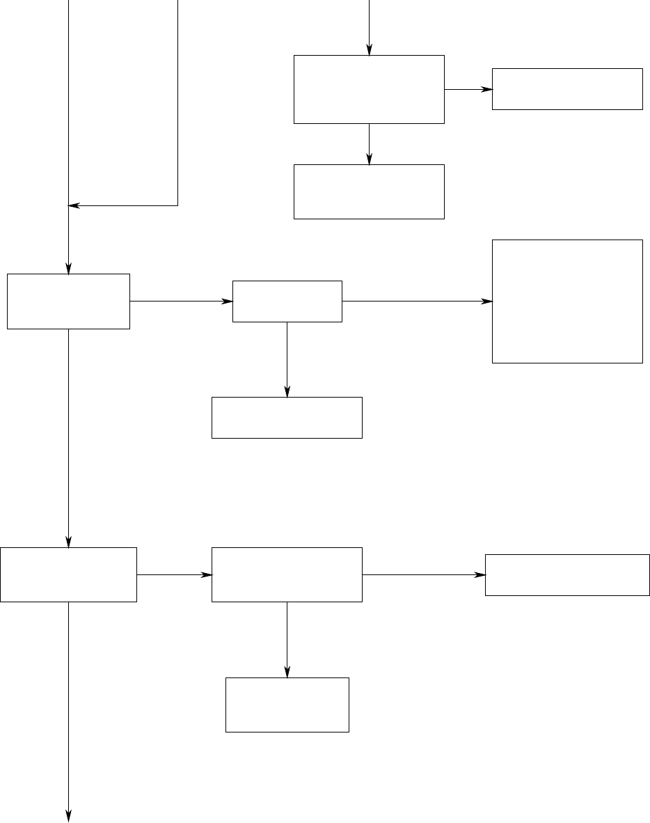
All installations and services must be performed by qualified service personnel.
CHECK CONNECTIONS
TO GAS VALVE. IF OK,
REPLACE GAS VALVE.
IS THE VARIABLE
SPEED AIR FAN
OPERATING?
DOES BLOWER
SPIN FREELY?
CONFIRM IF EITHER
BLOWER WHEEL
IS RUBBING AGAINST
HOUSING OR MOTOR
SHAFT IS SPINNING
FREELY AND REPAIR
OR REPLACE AS
NECESSARY
DOES SYSTEM RUN
UNTIL THERMOSTAT
IS SATISFIED?
CHECK ALL WIRING FOR
LOOSE CONNECTIONS.
NO
NO NO
NONO
YES
YES
YES
YES
YES
REFERENCE ECM
OPERATION MANUAL
IS THERE 24 VOLTS
ACROSS "MVH" AND
"MV COM" ON
50V51-843 CONTROL?
REPLACE THE
50V51-843 CONTROL.
IS LED LIGHT
ON 50V51-843
CONTROL FLASHING?
REFERENCE LED
CHART ON PG. 48
OF THIS MANUAL.
53
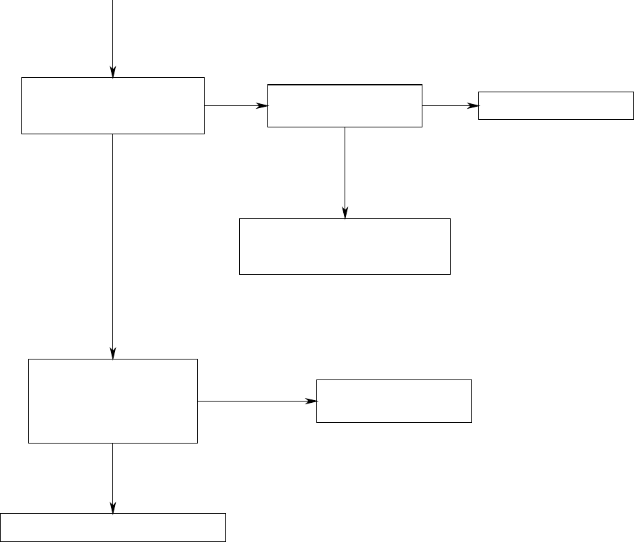
All installations and services must be performed by qualified service personnel.
DOES BURNER SHUT OFF
WHEN THERMOSTAT IS
SATISFIED?
CHECK FOR 24 VOLTS
AT GAS VALVE. REPLACE GAS VALVE
CHECK FOR SHORT IN WIRE TO
THERMOSTAT AND CORRECT
IF NECESSARY.
DOES THE CIRCULATING
AIR BLOWER TURN OFF
AFTER THERMOSTAT IS
SATISFIED WITHIN
120 SECONDS?
TROUBLE SHOOTING COMPLETE
NO NO
YES
YES
YES
NO REFERENCE ECM
OPERATION MANUAL
54
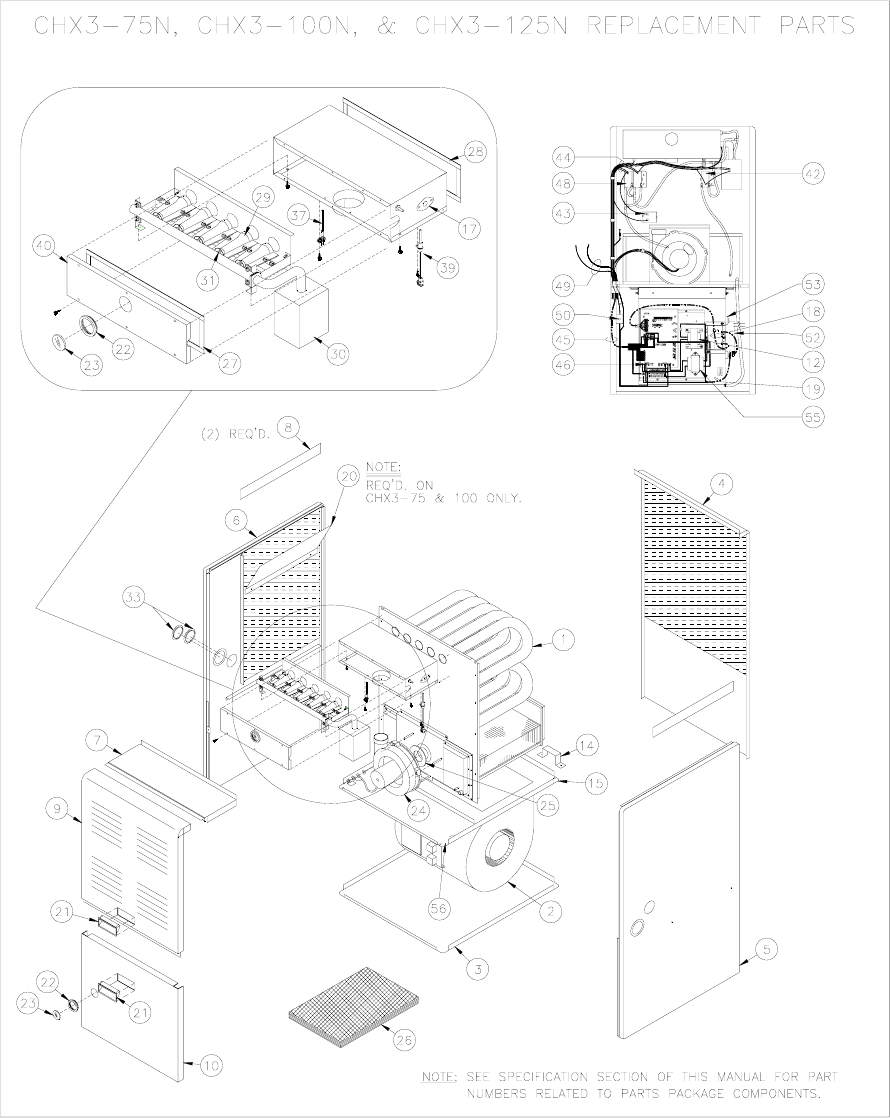
All installations and services must be performed by qualified service personnel.
Appendix –A Replacement Parts List
1. Replacement parts list for CHX3-75, CHX3-100 and CHX3-125.
55
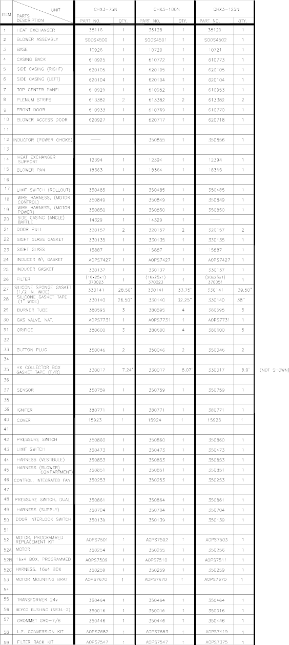
All installations and services must be performed by qualified service personnel.
56
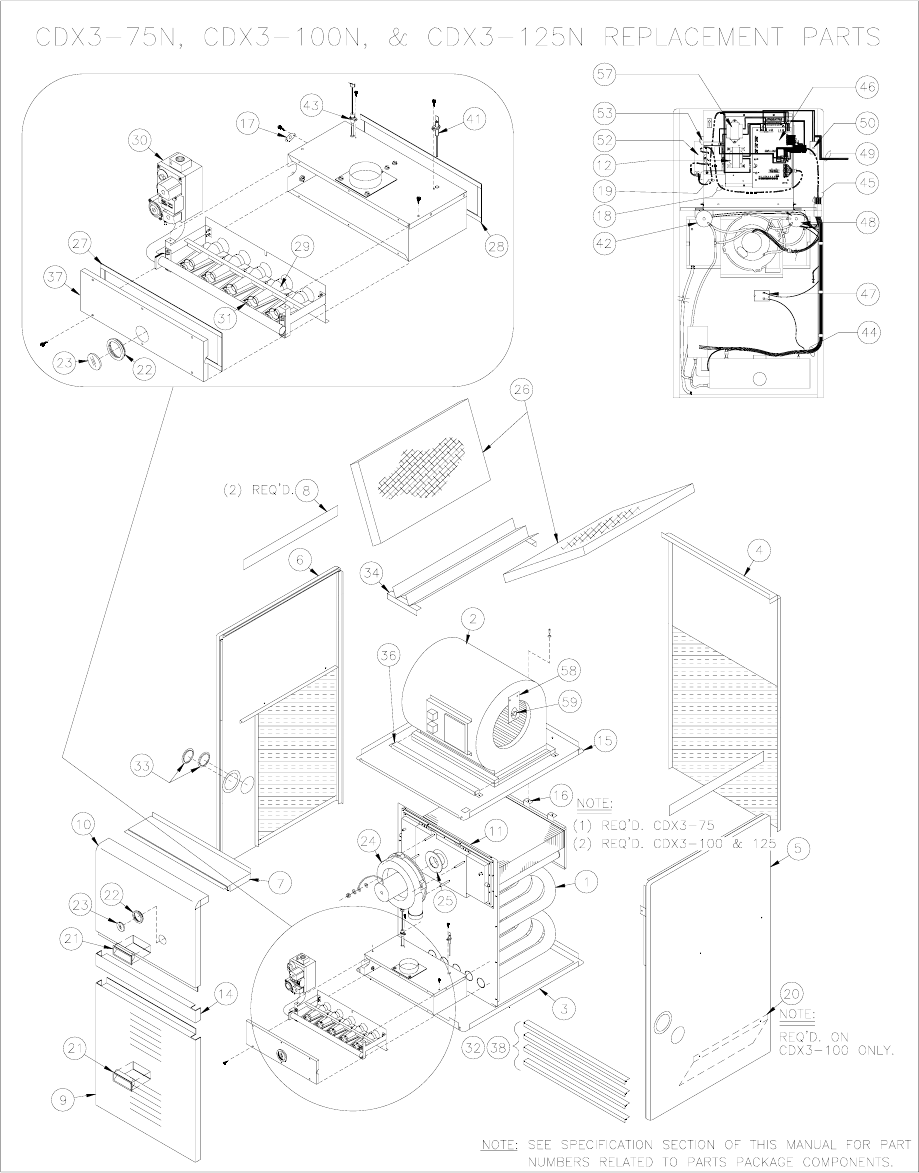
All installations and services must be performed by qualified service personnel.
2. Replacement parts list for CDX3-75, CDX3-100 and CDX3-125.
57
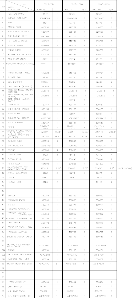
All installations and services must be performed by qualified service personnel. All installations and services must be performed by qualified service personnel.
58
58
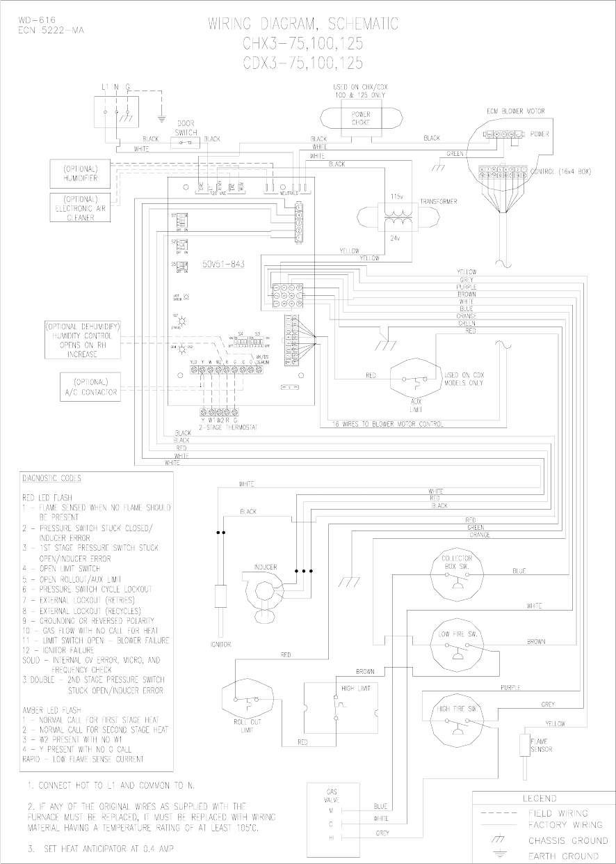
All installations and services must be performed by qualified service personnel.
Appendix – B Wiring Diagrams
59
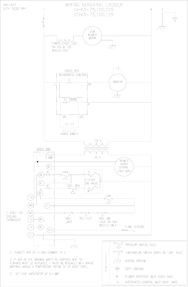
All installations and services must be performed by qualified service personnel. All installations and services must be performed by qualified service personnel.
60
60