Thermo Products Pride Furnace Oh6Fa072D48B Users Manual
OH6FA072DV4B to the manual 6921c182-d4b8-4aa2-b77c-2b439c147012
2015-02-03
: Thermo-Products Thermo-Products-Thermo-Pride-Furnace-Oh6Fa072D48B-Users-Manual-461681 thermo-products-thermo-pride-furnace-oh6fa072d48b-users-manual-461681 thermo-products pdf
Open the PDF directly: View PDF ![]() .
.
Page Count: 78
- MODEL:
- OH6FA072D48B OH6FA072DV4B OH8FA119D60B OH8FA119DV5B
- OH6FA072D48R OH6FA072DV4R OH8FA119D60R OH8FA119DV5R
- OH6FA072D48N OH6FA072DV4N
- CONTENTS
- Model Number Digit
- A
- F
- O
- Table 1: MINIMUM CLEARANCES TO COMBUSTIBLE MATERIALS
- Fig. 2: Proper chimney termination height for pitched roofs
- Fig. 3: Proper chimney termination height for flat roofs
- Fig. 4: Proper insertion of the vent connector in the chimney.
- REDUCTION OF CLEARANCES WITH SPECIFIED FORMS OF PROTECTION:
- ROTATION OF FRONT FLUE ELBOW:
- The OH6 & OH8 may be vented through a standard correctly sized chimney.
- The OH6 & OH8 may also be horizontally vented through a sidewall. Thermo Products has available the Field model FDVS-45/FOVP-415 and FDVS-67/FOVP-615 side wall vent kits for such applications. When installing the sidewall vent kits, outside combustion...
- C. DRAFT REGULATORS:
- Table 3: Suggested Duct Sizes for Homes, Quiet Offices, Or Similar Installations
- Fig. 9: Supply air duct sizing Example
- ROTATION OF FRONT FLUE ELBOW:
- E. Air Filter Mounted External to Furnace:
- Riello 2-stage burner specifications and applications (OH6 ONLY):
- I. OIL TANK AND PIPING:
- A. Inputs
- III. USERS INFORMATION SECTION
- MO-437 printing specifications.pdf
MO-437
ECN 5338-MA 140301 Made IN USA
OIL FIRED FURNACE
INSTALLATION AND OPERATION MANUAL
WITH USERS INFORMATION SECTION
MODEL:
OH6FA072D48B OH6FA072DV4B OH8FA119D60B OH8FA119DV5B
OH6FA072D48R OH6FA072DV4R OH8FA119D60R OH8FA119DV5R
OH6FA072D48N OH6FA072DV4N
OH6FX072DV4R
WARNING: IF THE INFORMATION IN THESE INSTRUCTIONS IS NOT FOLLOWED EXACTLY, A
FIRE OR EXPLOSION MAY RESULT CAUSING PROPERTY DAMAGE, PERSONAL INJURY, OR
LOSS OF LIFE.
DO NOT STORE OR USE GASOLINE OR OTHER FLAMMABLE VAPORS AND LIQUIDS IN THE
VICINITY OF THIS OR ANY OTHER APPLIANCE.
WARNING: IMPROPER INSTALLATION, ADJUSTMENT, ALTERATION, SERVICE, OR
MAINTENANCE CAN CAUSE INJURY OR PROPERTY DAMAGE. REFER TO THIS MANUAL. FOR
ASSISTANCE OR ADDITIONAL INFORMATION CONSULT A QUALIFIED INSTALLER, OR SERVICE
AGENCY.
PLEASE READ THESE INSTRUCTIONS PRIOR TO INSTALLATION, INITIAL FIRING, AND BEFORE
PERFORMING ANY SERVICE OR MAINTENANCE. THESE INSTRUCTIONS MUST BE LEFT WITH
THE USER AND SHOULD BE RETAINED FOR FUTURE REFERENCE BY QUALIFIED SERVICE
PERSONNEL.
THERMO PRODUCTS, LLC.
PO BOX 217
NORTH JUDSON, IN 46366
PHONE: (574) 896-2133

i
CONTENTS
SECTION PAGE
I. SAFETY SECTION 1
A. CODES AND CLEARANCES 3
B. MAKE-UP AIR 4
II. GENERAL INSTRUCTIONS 5
A. CHIMNEY 6
B. VENTING 10
C. DRAFT REGULATORS 11
D. DUCT WORK/AIR CONDITIONING 11
E. AIR FILTER(S) 15
F. LIMIT POSITION AND LOCATION 17
G. BURNER INSTALLATION 18
H. BURNER SPECIFICATIONS AND APPLICATIONS 19
I. OILTANK AND PIPING 22
J. OIL FILTER 23
K. ELECTRICAL WIRIING 23
L. BLOWER SETUP 27
M. BLOWER CONTROLLER INFORMATION FOR PSC MOTOR 35
N. STARTUP PROCEDURES 40
III. USERS INFORMATION SECTION 48
A. OIL SUPPLY 48
B. COMBUSTION AIR SUPPLY 48
C. INSPECTION AREAS 48
D. STARTING THE BURNER 49
E. FILTER CLEANING AND LOCATION 49
IV. INSTALLER'S INSTRUCTIONS TO USER 50
V. DEALER MAINTENANCE 51
A. GENERAL INSPECTION 51
B. HEAT EXCHANGER 52
C. HEAT EXCHANGER CLEANING INSTRUCTIONS 52
D. ELECTRICAL SYSTEM 54
E. SUPPLY/RETURN AIR BLOWER 54
F. SUPPLY/RETURN AIR FILTER 54
G. EXTENDED APPLIANCE SHUTDOWN 55
VI. HOMEOWNER/USER INFORMATION AND ROUTINE MAINTENANCE 56
VII. TROUBLESHOOTING 58
A. DIAGNOSTICS 59
B. CAD CELL CHECK-OUT PROCEDURE 59
VIII. SEQUENCE OF OPERATIONS FLOW CHART 61
IX. TROUBLE SHOOTING FLOW CHART 63
APPENDIX – A
REPLACEMENT PARTS LIST 69
APPENDIX – B
WIRING DIAGRAMS 71

ii
Model Number Digit
1
2
3
4
5
6
7
8
9
10
11
12
Fuel
Configuration
Heat Exchanger
Identifier
Flue
Feature
Capacity
Capacity
Capacity
Blower Type
Clg Airflow Cap.
Clg Airflow Cap.
Burner
Oil Furnace Model Nomenclature Example Model Numbers
O
H
6
F
A
0
7
2
D
4
8
B
O
H
6
F
A
0
7
2
D
V
4
R
O
H
8
F
A
1
1
9
D
6
0
B
O
H
8
F
A
1
1
9
D
V
5
R
O = Oil
O
H = Highboy D = Downflow
H
6 = Heat Exchanger Size Identifier
6
F = Front
F
R = Rear
R
A = Single Stage
A
X = 2-Stage
X
Heating Capacity MBTUH (000's) with factory installed nozzle
0
7
2
D = Direct Drive
D
Clg. Airflow: Example = 48MBTUH = 4 tons @ 400cfm/ton
4
8
Clg. Airflow Variable Speed (ECM) V5 = 5tons
V
5
B = Beckett, R = Riello, N = Beckett NX
B

1
I. SAFETY SECTION
This page and the following contains various warnings and cautions found
throughout the Oil Furnace Manual. Please read and comply with the statements
below.
WARNING AND CAUTIONS:
WARNING: This furnace is not to be used as a construction heater. See Page 3
WARNING: The predetermined limit locations on all of the Thermo Pride oil fired
furnaces have been tested and approved by Thermo Products, LLC. Any attempt to
relocate these safety controls or replace these safety controls with a control that is not
approved, or is incompatible, may result in personal injury, substantial property damage
or death. See Page 17
WARNING: THE HEAT EXCHANGER MUST BE CLEANED BY A QUALIFIED
SERVICE PERSON. See Page 52
CAUTION: DO NOT ATTEMPT TO MAKE REPAIRS YOURSELF! See Page 48
WARNING: The area around the furnace should be kept free and clear of
combustible liquids and material, especially papers and rags. See Page 3
WARNING: NEVER burn garbage or refuse in your furnace. Never try to ignite
oil by tossing burning papers or other material into your furnace. See Page 48
WARNING: Thermo Products oil furnaces are designed to burn No. 1 or No. 2
distillate fuel oil. NEVER USE GASOLINE OR A MIXTURE OF OIL AND GASOLINE.
See Page 48
CAUTION: DO NOT ATTEMPT TO START THE BURNER WHEN:
1. Excess oil has accumulated,
2. The furnace is full of vapors
3. The combustion chamber is very hot.
IF ONE OR MORE OF THESE CONDITIONS EXIST, CONTACT A QUALIFIED
SERVICE PERSON. See Page 48
WARNING: DO NOT START BURNER UNLESS BLOWER DOOR IS SECURED IN
PLACE.
2

3
The entire text of these instructions must be read and understood, before
installing the appliance. It is the installer's responsibility to do the following:
1. Inform and demonstrate to the user, the correct operation and maintenance of the appliance, as
explained in the Homeowner/User Information and Routine Maintenance section of this manual.
2. Inform the user of the hazards of flammable liquids and vapors and to remove such liquids and
vapors from the vicinity of the appliance.
3. Inform the user of all pertinent warnings and precautions concerning this appliance.
WARNING: This unit is not to be used for temporary heating of buildings, or structures, under
construction. Construction dust may enter the appliance or the duct system and cause a fire hazard.
Certain chemicals used during construction when burned, form corrosive condensate that can
substantially reduce the life of the heating system heat exchanger.
This appliance is shipped completely assembled and internally wired. All electrical wiring has been factory
installed and inspected. At the time of installation, the unit will require connection to electric power, fuel oil
supply, and supply and return air ductwork. In the event of a shortage of parts or damage, contact
Thermo Pride office.
This unit uses a fan-assisted combustion system, consisting of a pressure atomizing, oil burner and
combustion air blower, used to push the products of combustion through the heat exchanger system.
After installation, the furnace and duct system must be adjusted to obtain a temperature rise of 51°F to
81°F through the unit. (Refer to the rating label located on side panel inside the burner compartment).
The installation must conform with local codes or, in the absence of local codes, with the Standard for the
Installation of Oil-Burning Equipment, NFPA 31-1997, or the latest edition, and to these instructions. The
installation must also comply with CSA B139 for recommended installation practices where applicable.
A. CODES AND CLEARANCES:
The following items must be considered when choosing the size and location of the unit.
1. All local codes and/or regulations take precedence over the instructions in this manual and
should be followed accordingly. In the absence of local codes, installation must conform to these
instructions and the guidelines of the National Fire Protection Association (NFPA). Two applicable
NFPA installation codes are the National Electrical Code, ANSI/NFPA 70-1999, and Standard for the
Installation of Oil-Burning Equipment, NFPA 31-1997. The latest editions of these codes should be
consulted.
2. The selection of a heating unit should be based on a rate of heat loss calculation for the residence
according to the manuals provided by the Air Conditioning Contractors of America (ACCA) or the
American Society of Heating, Refrigeration, and Air Conditioning Engineers (ASHRAE). The heating
capacity of the unit proposed for installation should meet or slightly exceed the rate of heat loss for the
residence. Over sizing should not exceed 25% of the heat loss calculation.
3. When installed, this unit should be level. If possible, it should be installed in a central location, with
respect to outlet registers of the supply air ductwork.
4. Definitions of "combustible" and "non-combustible" materials as presented in the 1996 version of the
National Fuel Gas Code, ANSI Z223.1-1996/NFPA 70-1996, are as follows:
a. Combustible material:
“...materials made of or surfaced with wood, compressed paper, plant fibers, or
other materials that are capable of being ignited and burned. Such materials
shall be considered combustible even though flame proofed, fire-retardant
treated, or plastered.”
4
b. Non-combustible material:
“...material that is not capable of being ignited and burned; such as material
consisting entirely of, or a combination of, steel, iron, brick, concrete, slate,
asbestos, glass, and plaster.”
: Carefully read and thoroughly understand the following guidelines and warnings
before continuing with the installation of this appliance. Failure to follow these guidelines can
cause improper and unsafe operation of this appliance. Unsafe operation can result in substantial
property damage, severe personal injury, or death.
1. This appliance shall be used with only the type of fuel oil for which it is approved. Refer to the
appliance-rating label for the required type of fuel.
2. This appliance is an oil-fired furnace designed for installation on non-combustible materials. This
appliance is also approved for attic installation on non-combustible materials.
3. Ensure that adequate combustion and ventilation air is available to the unit.
4. The airflow resistance of the duct system attached to this appliance must fall within the allowable
external static pressure range for this unit. Refer to the Airflow Requirements and Sizing of
Ductwork section of this manual.
5. Make sure supply and return air ducts are completely sealed to the appliance casing. Refer to the
Airflow Requirements and Sizing of Ductwork section of this manual.
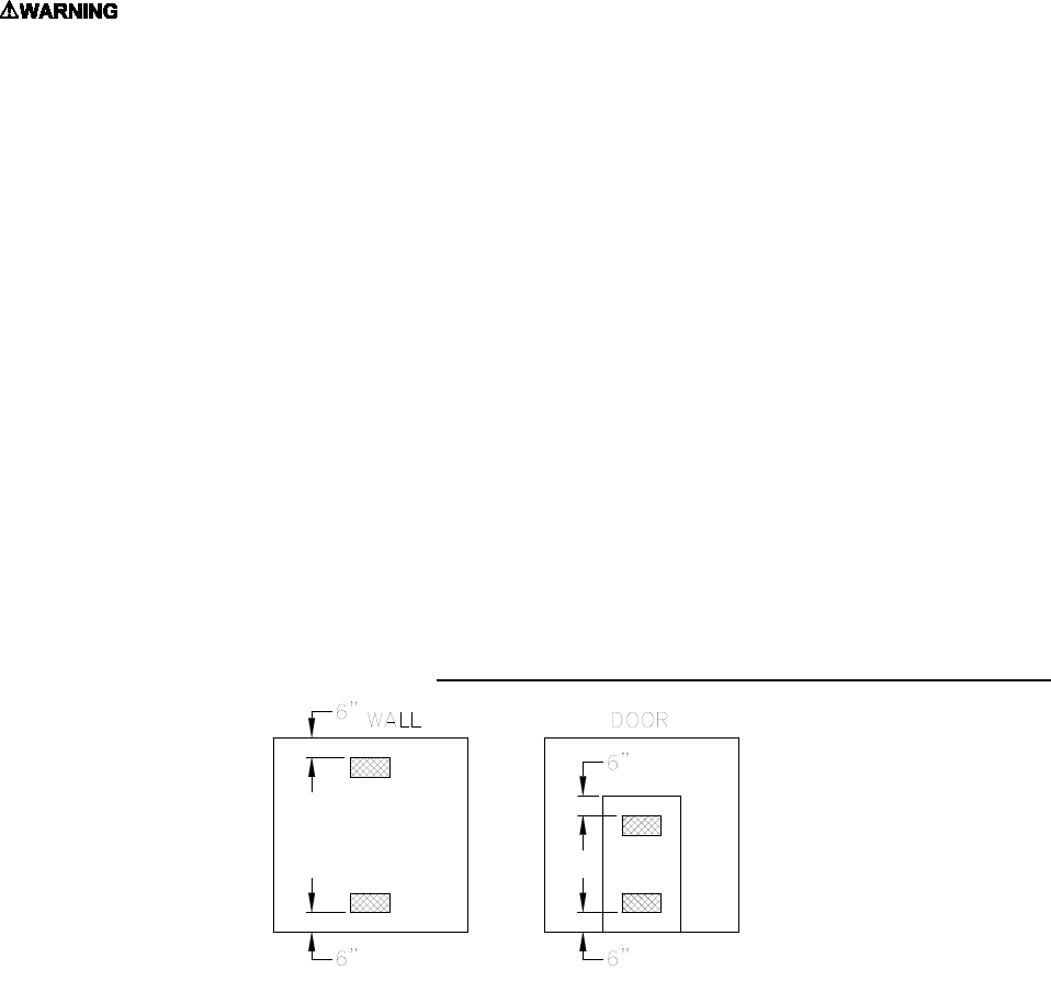
This area in which the furnace is located must have adequate supply of air for combustion and draft control
operation. The minimum required volume of free air should be 50ft³/1000 btu (per NFPA 54). However, if the
furnace is located in an area of the building that doesn’t meet this requirement, two openings into another room
are recommended (each opening having a free area of 1 square inches per 1,000 BTUH input of the total input
of all appliances located in the room). If these openings are in a wall, they must be at least 6 inches from the
ceiling and floor (Fig. 1A) or they are in a door, they must be at least 6 inches from the top of the door and 6
inches from the bottom of the door (Fig. 1B). THESE OPENINGS MUST BE FREE AND UNOBSTRUCTED.
Fig 1: Properly Positioned Combustion Air Openings In Walls (Fig. 1A) and Doors (Fig. 1B).
B. MAKE-UP AIR: Today's emphasis on home insulation increases the probability of inadequate air
supply to the furnace. Heavy insulation cuts off infiltration of outside air, which previously replaced inside
air removed by bathroom, kitchen and laundry vent fans, and air escaping up chimneys. This causes a
negative pressure differential within the home that reduces the supply of air available to the furnace for
combustion and ventilation.
The Thermo Pride Make-Up-Air Control, installs quickly and easily on any warm air heating system,
delivers controlled, fresh air automatically during the winter and a constant supply of clean, fresh air for
comfortable summer living. It resolves the negative pressure differential problem.

5
II. GENERAL INSTRUCTIONS - READ BEFORE START OF INSTALLATION
1. The heating output capacity of the furnace proposed for installation should be based on a heat loss
calculation made according to the manuals provided by the Air Conditioning Contractors of America
(ACCA) or the American Society of Heating, Refrigeration and Air Conditioning Engineers, Inc.
(ASHRAE).
2. All local codes and/or regulations take precedence over the instructions in this manual and should be
followed accordingly. In the absence of local codes, installation must conform with these instructions and
regulations of the National Fire Protection Association, and to the provisions of the National Electrical
Code (ANSI/NFPA 70-1999 or latest edition).
3. The installed furnace must be level and positioned in a central location with respect to outlet registers.
It should be located near the chimney to minimize any horizontal run of flue pipe, which may be required.
4. A furnace installed in a residential garage must be installed so the burner and ignition source are
located higher than 18 inches above the floor. The furnace must also be located or protected to avoid
physical damage by vehicles.
WARNING: This furnace is not to be used as a construction heater.
5. Listed below are definitions of "COMBUSTIBLE MATERIAL" and "NON-COMBUSTIBLE MATERIAL."
Combustible Material: is made of or surfaced with wood, compressed paper, plant fibers, plastics, or
other material that will ignite and burn, whether flame resistant or not.
Non-Combustible Material: is material that is not capable of being ignited and burned. Such materials
consist entirely of, or a combination of, steel, iron, brick, tile, concrete, slate, or glass.
Table 1: MINIMUM CLEARANCES TO COMBUSTIBLE MATERIALS
TYPE OF
UNIT MODEL NO.1 FROM
SIDES OF
FURNACE FRONT TOP &
SIDES OF
PLENUM
FROM THE
FLUE/VENT REAR
Highboy OH6FA072D*** 0” Note 1 1” 7” 0”
Highboy
OH8FA119D*** 0” Note 2 1” 8” 0”
Note: 1 OH6 front clearance 6” for Closet, 24” for Alcove.
2 OH8 front clearance 8” for Closet, 24” for Alcove.
The minimum clearances listed in the preceding table are for fire protection. Clearance for servicing the
front of the furnace should be at least 24 inches.
NOTE: The OH6 & OH8 furnaces are approved for closet installation. If the OH6 is installed in a closet, it
requires two openings in the closet door for combustion air, each having a minimum area of 162 sq.
inches. The OH8 requires two openings in the closet door, each having a minimum area of 181 sq.
inches. This free area intentionally exceeds the recommended minimum free area of 1 square inch per
1000 BTUH of input rate.

6
A. CHIMNEY:
The furnace must be connected to an adequate chimney or an approved vent in accordance with these
instructions. An adequate chimney is one that is sealed and lined with the capability of producing a (-).04"
WC flue draft and having the capacity to handle the amount of stack gases that are introduced into it. A
chimney with an internal construction of corrosion resistant tile, stainless steel, or some other material
that will withstand flue gas temperatures up to 900°F is required.
Qualified service personnel must perform all installations and services.
The following are common chimney requirements necessary for the furnace to operate correctly:
A masonry chimney serving a Thermo Pride oil fired furnace must comply with local codes and NFPA
Standard for Chimneys, Fireplaces, Vents, and Solid Fuel Burning Appliances (NFPA211-1996 or latest
edition).
1. PREVENTION OF CHIMNEY CONDENSING:
Stack gas may do one of two things as it escapes up the chimney:
A. Remain entirely in a gaseous state if the internal chimney wall temperature is above the dew
point
B. Condense water vapor on the chimney walls if they are chilled below the dew point.
Condensing will always occur on chimney walls whose temperatures are below the dew point, but the
condensate may evaporate when the walls warm above the dew point. If the chimney wall temperature
does not exceed the dew point during the heating cycle of the furnace, the moisture may accumulate in
large enough quantities to cause problems such as corrosion of a metal chimney (especially plain steel or
galvanized steel), erosion and break up of a tile liner in a masonry chimney and, in severe cases,
corrosion of the heat exchanger. Condensate also could enter the home through cracks or joints in the
chimney in a worse case situation.
Condensation most likely will not occur at the bottom of the chimney because the stack gas heats the
chimney walls as it rises and the bottom will be heated first. This heating of the walls will cause the stack
gas temperature to drop, which in turn may reduce the stack gas temperature below dew point, causing
condensation to appear on the upper part of the chimney first. This condensation may then run down
inside the chimney and drip back as far as the flue pipe and heat exchanger, where corrosion may occur,
if not treated.
To prevent condensation, it is necessary that the internal chimney wall temperature always be kept above
the dew point. If the chimney is a masonry type, it may have to be fitted with a flue liner, when the
temperature loss is too great for the furnace. If the chimney is a metal type, then an "all fuel" chimney
must be used, such as a Class "A" triple wall or insulated metal chimney. A liner will act as an insulator
and reduce the stack gas temperature loss. Insulation may be added around the liner for further
temperature stability. If the chimney is on the home's exterior or passes through a sizable, unheated area
of the building, such as a porch, high ceiling attic, etc., and condensing occurs, the chimney must be
insulated around its exterior to help the flue hold its temperature. Also, check to see if the chimney is too
large for the furnace and other appliances connected to it. If so, reduce to proper size (see Appendix E of
NFPA31) by lining. Be sure to use stainless steel liners, such as stainless types 430, 304, or for the
toughest corrosion problems, type 316. If the chimney is the correct size for the unit and condensing still
occurs, then insulating the vent connector and/or reducing the efficiency of the furnace may have to be
done to raise the chimney temperature.
More detailed information may be obtained from the latest edition of the ASHRAE HVAC Systems and
Equipment Handbook.
7
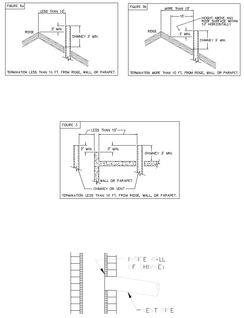
2. PROPER CHIMNEY HEIGHT:
The chimney shall terminate at least 3 feet above the highest point where it passes through the roof of a
building and at least 2 feet higher than any portion of a building within a horizontal distance of 10 feet.
(See Fig. 2a).
Fig. 2: Proper chimney termination height for pitched roofs
If the chimney penetrates a roof more than 10 feet from a ridge, wall or parapet, a minimum of 3 feet
above roof or exit point must be maintained. See Figure 2b.
If the roof is flat rather than the normal residential pitched roof, refer to Figure 3 for proper clearances.
Fig. 3: Proper chimney termination height for flat roofs
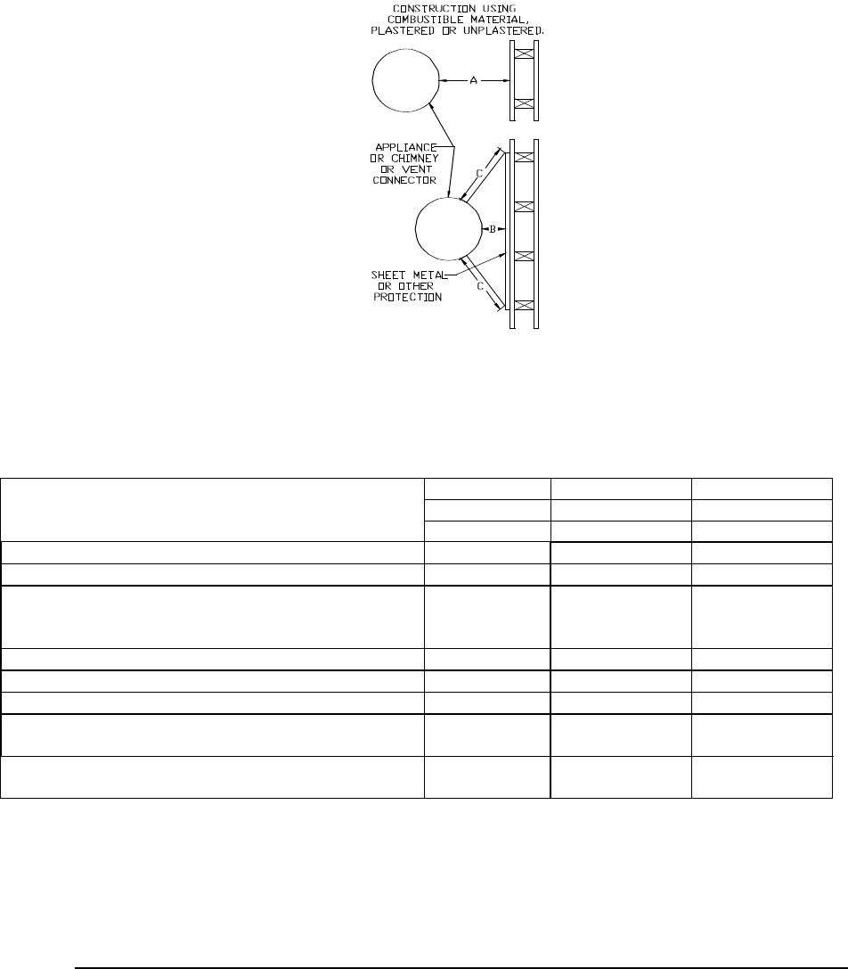
3. PROPER VENT CONNECTOR PIPE/CHIMNEY CONNECTION:
The vent connector pipe should extend only to (and not beyond) the inside wall of the chimney (See Fig.
4). A thimble should be used to connect the vent connector pipe to the chimney so that the vent
connector pipe may be readily removed in case of inspection or replacement.
Fig. 4: Proper insertion of the vent connector in the chimney.
8
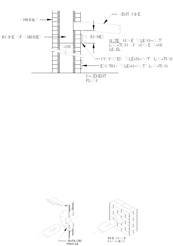
4. PROPER CHIMNEY BOTTOM LEVEL:
In cases where the chimney extends to the basement floor, the draft can usually be improved by filling the
base of the chimney with sand to within 12 inches of the vent connector pipe after relocating the clean-out
door. (See Fig. 5).
Fig. 5: Suggested method to improve chimney draft.
5. TIGHT JOINTS:
All joints of the chimney must be tightly sealed. The inside of the chimney should be free of any
obstructions, such as loose brick, broken pieces of tile, or corroded metal.
6. TIGHT CLEAN-OUT DOORS AND CONNECTIONS:
All chimney clean-out doors and flue connections must fit tightly so they will seal to avoid air leaks.
7. NO INTERCONNECTED CHIMNEY FLUES:
If chimney flues are divided or there are multiple flues within one chimney, make sure there are no
openings in the partition separating the divided or individual flues.
8. FLUE PIPE CLEARANCES, SIZING AND TYPE:
The vent connector pipe must not pass through a combustible wall or partition unless adequate protection
is provided at the passageway. An acceptable passageway could be either an approved, ventilated metal
thimble which is at least 12 inches larger in diameter than the vent connector pipe, or brick work which is
at least 8 inches thick constructed into the wall and surrounding the vent connector pipe. (See Fig. 6) on
the next page.
Fig. 6: Suggested method to accommodate vent connector passage through a wall composed of a combustible material.
9
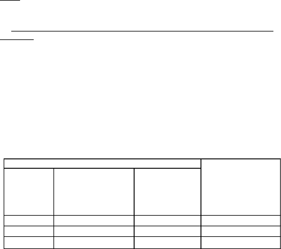
Fig. 7: Alternate constructions that allow reduced clearances to combustible materials.
REDUCTION OF CLEARANCES WITH SPECIFIED FORMS OF PROTECTION:
Type of protection applied to and covering all surfaces of combustible material within the distance
specified as the required clearance with no protection unless otherwise noted, all dimensions in inches,
refer to Fig. 7.
Required clearance with no protection from the appliance or
chimney connector is:
18 inches
9 inches
6 inches
Sides &
Sides &
Sides &
Above Rear
Above Rear
Rear
a. 3-1/2" thick masonry wall without ventilation air space….
-- 12
-- 6
-- 5
b. 1/2" insulation board over 1" glass fiber or mineral wool batts…
12 9
6 5
4 3
c. 0.024(24 gauge) sheet metal over 1" glass fiber or mineral
wool batts reinforced with wire on rear face with ventilated air
space…
9 6
5 3
3 3
d. 3- 1/2" thick masonry wall with ventilation air space..
-- 6
-- 6
-- 6
e. 0.024 (24 gauge) sheet metal with ventilated air space.
9 6
5 3
3 2
f. 1/2" thick insulation board with ventilation air space..
9 6
5 3
3 3
g. 0.024 ( 24 gauge) sheet metal with ventilated air space over
0.024 (24 gauge) sheet metal with ventilated air space….
9 6
5 3
3 3
h. 1" glass fiber or mineral wool batts sandwiched between two
sheets 0.024 (24 gauge) sheet metal with ventilated air space
9 6
5 3
3 3
A. Equal the required clearance with no protection.
B. Equals the reduced clearance permitted in accordance with the preceding clearance chart.
C. The protection applied to the construction that covers the combustible material should extend far enough
in each direction to make C equal to A.
The vent connector pipe between the furnace and chimney shall be of equal diameter as the flue outlet of the
furnace. The vent connector pipe must be made of 24 gauge (or thicker) corrosion-resistant steel. The
vent connector pipe should be as short as possible and installed so that it has a continuous rise from the
furnace to the chimney. The horizontal length of a connector to a natural draft chimney or vent serving a single
appliance shall not be more than 75 percent of the height of the vertical portion of the chimney or vent above
the connector. Elbows should be minimized and the pipe should be joined with metal screws and supported by
straps. All horizontal runs of vent connector pipe should be pitched upward a minimum of ¼ inch per foot of run.
A thimble should be used to connect the vent connector pipe to the chimney so the pipe may be readily
removed in case of inspection or replacement. See Fig. 6 on preceding page.
10
B. VENTING:
NOTE: On the OH6 & OH8 it is possible to rotate the flue elbow (which is factory installed for vertical
discharge) 90° counter clockwise from the vertical position to adapt to various venting systems. The OH8
flue elbow can also be rotated 90° clockwise.
Notice: Blocked Vent Switch Installation
The blocked vent switch kit must be installed to comply with CAN STD B140.4 where applicable. For
installation instructions see AOPS2687 kit.
CAUTION MUST BE TAKEN NOT TO EXCEED 90° ROTATION (OF THE FLUE
ELBOW) .
ROTATION OF FRONT FLUE ELBOW:
When an installation requires that the flue exit out the left (or right OH8 only) side casing, remove screw
securing the 90 deg. elbow and rotate it 90°. Then, remove knock-out in side casing and extend vent
through the opening.
A trim collar may be ordered from Thermo Products to hide the gap around the flue pipe. This trim collar,
however, is not required for operation. Trim collar/gasket part numbers(s) 14121 / 330073 for OH6 and
14132 / 330006 for OH8.
The OH6 & OH8 may be vented through a standard correctly sized chimney.
The OH6 & OH8 may also be horizontally vented through a sidewall. Thermo Products has available the
Field model FDVS-45/FOVP-415 and FDVS-67/FOVP-615 side wall vent kits for such applications. When
installing the sidewall vent kits, outside combustion air must also be applied to the burner. The following
table identifies application order information.
Table 2: Sidewall vent kits
The Field vent kit is set up with 4 inch diameter vent pipe for OH6 and 6 inch diameter vent pipe for the
OH8 with concentric through-the-wall vent termination/inlet air vent hood. The combustion air inlet pipe
diameter is also 4 inch diameter. For Riello, the combustion air inlet pipe will be reduced to 3 inch
diameter with the Riello sidewall vent kit. For Beckett, the combustion air inlet pipe will be reduced to 3”
diameter with the Beckett sidewall vent kit.
The side wall vent may be installed either through the knock-out on the right or left side casing of the unit
or vertically out the top opening of the vestibule.
The combustion air inlet can be installed through the either the lower left side casing knockout or the
lower right side casing knockout.
FIELD VENT TERMINATION
KIT
SIDE WALL VENT
ACCESSORIES KIT
COMBUSTION AIR INTAKE
HOOD KIT
(15’ application MAX) (BURNER SPECIFIC)
(FOR COMBUSTION AIR
APPLICATIONS ONLY)
THERMO PRODUCTS PART
NUMBER
THERMO PRODUCTS
PART NUMBER
THERMO PRODUCTS PART
NUMBER
(OH6) (OH8)
Beckett AFG AOPS8393 AOPS8414 AOPS8394 AOPS8397
Riello BF3 AOPS8393 AOPS8414 AOPS8395 AOPS8416
Beckett NX
(OH6 ONLY)
AOPS8393 N/A AOPS8412 AOPS8413
BURNER
SIDE WALL VENTING APPLICATION ORDER INFORMATION
11
C. DRAFT REGULATORS:
Note: Do not use with Direct Vent application.
A draft regulator is supplied with the furnace and should be installed according to the regulator
manufacturers recommendations. With the burner operating, use a draft gauge to adjust the regulator to
the proper setting. (refer to the instructions enclosed with draft regulator to adjust to the proper setting).
When the burner air supply and draft are properly adjusted, the over fire draft should be a negative (-).01"
to (-).02" WC, as measured at the 5/16" over fire air tap (See Fig. 12). This tap is provided in the upper
burner mounting plate. To measure the flue draft, punch a small hole in the vent connector pipe as close
to the furnace as possible and always before the draft regulator.
Note: Draft over fire may be positive for high fire applications but not to exceed (+).02" WC.
D. DUCT WORK/AIR CONDITIONING:
If the furnace is used in connection with summer air conditioning (cooling), the furnace should be installed
parallel with or on the upstream side of the evaporator coil to avoid condensation in the furnace heat
exchanger. If the cooling unit is installed with a parallel flow arrangement, dampers or other means used
to control flow of air should be provided to prevent chilled air from entering the furnace. If such a damper
is manually operated, it must be equipped with a means to prevent operation of either unit, unless the
damper is in the full heat or cool position.
The duct system should again follow the current design standard of Air Conditioning Contractors of
America (ACCA) or ASHRAE Fundamentals volume. The most common location for the A-shaped coil (A
style) is shown in Fig. 8.
Fig 8: Acceptable locations for the air conditioner evaporator coil.
NOTICE: The minimum coil pan clearance for a sectional or drum type heat exchanger is three inches
unless specified otherwise by the individual coil manufacturer.
NOTICE: The minimum return air temperature is 55° F.
Airflow Requirements and Sizing of Duct Work:
The duct system must be sized and installed by a qualified installer or service person, following the
design standards of the Air Conditioning Contractors of America (ACCA) or the American Society of
Heating, Refrigeration, and Air Conditioning Engineers (ASHRAE). This furnace has been designed to
operate against a maximum external static pressure of 0.5 in. W.G. This is equivalent to 0.1 in.
W.G. supply, and 0.1 in. W.G. return, and 0.3 in. W.G. for evaporator coil.
12
1. Supply and return air ducts have to be furnished by the installer and run between the appliance,
which must be installed outdoors, and the interior of the structure the appliance serves. These ducts
must be sealed to the casing of the appliance.
2. To reduce the transmission of vibration and noise to the duct system and to reduce flexure of the duct
system due to thermal expansion and contraction, it is recommended that flexible joints be installed at
the supply and return duct connections to the unit.
3. The return air duct system must equal the supply air duct system in the flow capacity (CFM) for a
given pressure drop. Use a supplier's catalog for proper sizing of outlet and return air registers and
grills to ensure that they meet the flow requirements of the run to which they are connected.
4. The duct system shall be sized to provide the maximum airflow rate (CFM) required of the installation.
Two common rules for determining minimum airflow in heating and cooling systems follow:
a. For heating, 14 CFM of airflow are required per 1000 BTU/hr of heat output, based on
steady state operation and a 51° to 81° temperature rise.
b. For cooling, 400 CFM of airflow are required per ton of air conditioning. (For reference, a
ton of A/C = 12,000 BTU/hr removed from the space.)
Refer to Examples 1 & 2, (page 15) for a sample calculation of how to determine the required
minimum airflow rate.
5. Duct sizing is based upon both air velocity and pressure drop considerations. When possible, current
practice favors designing ductwork for lower air velocities. (For residences, a maximum air velocity of
800 FPM is suggested.) This results in quieter duct systems, systems which require less fan power
(reduced operating costs), and less carefully constructed ductwork (lower initial costs).
However, lower air velocities also result in larger duct sizes than necessary at higher velocities. In
some cases, space restrictions may limit the ductwork to smaller than optimal sizes.
6. The following method can be used to size ductwork when air velocities are low to moderate.
a. Using a floor view of the residence, determine, or layout, the locations of the supply registers
and the return air grills. (Generally, supply registers should be located close to sources of
heat loss, i.e. windows and doors, around the perimeter of the building. Return grills should
be located in central positions as far away from the supply registers as practical.)
b. Find a location for the appliance that minimizes the amount of ducting required to connect the
appliance to the supply and return air duct systems. Consider issues of access to the oil
supply and electrical service, required service and venting clearances, and operating noise
when selecting this location.
c. Plan an efficient layout for the ductwork connecting each of the supply air registers in the
supply system to the unit. Plan and layout ductwork connecting each of the return air grills in
the return system to the unit. Measure or estimate the length of duct between each register
and grill.
d. Select values for the airflow through each register and grill.
e. Select values for the pressure drops of both the supply and return air systems. Each branch
of the supply (or the return) air system will have this pressure drop. The total pressure drop of
the supply and return air systems added together cannot exceed the maximum external static
pressure that can be supplied by the appliance blower.
f. Determine the required flow rate for each branch of the supply and return air systems. The
total airflow rate, by adding the airflow rate of each branch of the supply system, must equal
the minimum required airflow rate (refer to part 3, above). Likewise, the airflow rate of each of
the branches of the return air system must sum to the required minimum flow rate.

13
g. Using the selected air flow rates for each component of the duct system and manufacturer’s
literature, or published literature on duct system pressure drops, the pressure drop for each
component in the duct system can be estimated.
The ASHRAE Handbook – Fundamentals is an excellent source of duct system design principles
and pressure drop data. Conversely, for a specified type of fitting, it is also possible to determine
the required size or diameter of the component for a specified pressure drop and flow rate.
h. The resistance of the take-off and the outlet register (or return grill) should then be summed
together to determine the total pressure drop for each branch. This value should be close to
the assumed value for the pressure drop of the system. If it is not close, then flow rates for
each branch must be adjusted, or the design of the duct system must be altered, to give the
proper pressure drops. Usually, the cross-sectional area of the ductwork should be changed
in order to adjust the pressure drop to a suitable value. Refer to Example 2, (page 14) for a
sample calculation of how to use this method for sizing the supply side ductwork for a
residence.
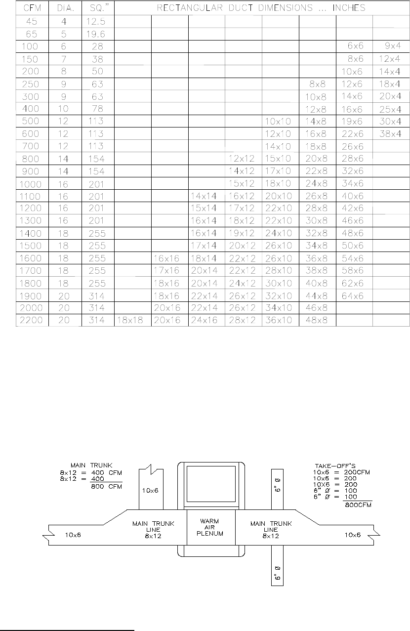
Table 3 shows the air handling capacities of 100-ft. lengths of circular and rectangular
ductwork based on a 0.1 in. W.G. static pressure drop. The first column to the right is the
airflow rate and the second is the required diameter for a circular duct. The third column is
the required cross-sectional area of the duct and the other columns to the left are rectangular
ducts with sufficient cross-sectional area to handle the flow at the specified pressure drop.
[For lengths of ductwork less than 100 ft., simply multiply 0.1 in. W.G. by the ratio of the
actual duct length (in feet) over 100 ft. for the approximate pressure drop.] Use the supplier’s
catalog for proper sizing of outlet air registers and return air grills to insure that they provide
the required flow rate at the desired pressure drop.
14
Table 3: Suggested Duct Sizes for Homes, Quiet Offices, Or Similar Installations
(Based on a 0.1 in. W.G. static pressure drop per 100 ft. of duct.)
7. The supply and return air ducts, or flexible joints, should be carefully secured and sealed to the
appliance housing to prevent air leakage from, or into, the duct system. For best performance,
insulate the outside surfaces of the ducts to reduce heat loss from, or heat gain to, the ducts.
8. As a final step in the installation, the appliance must be adjusted to deliver a temperature rise within
the range of 51° to 81°F. Adjust the blower motor speed to obtain a temperature rise within the
acceptable range. The required blower speed will depend on the airflow resistance of a supply and
return air duct systems.
Fig. 9: Supply air duct sizing Example
The RETURN AIR DUCT SYSTEM should equal the warm air duct system in airflow capabilities.
NOTE: When a return register is located in the same room as the furnace, the register must be at least 20
feet away from the furnace.

15
SIZING THE DUCT WORK FOR A COMBINATION HEATING AND COOLING SYSTEM:
Two formulas must be used in determining the CFM requirements of a combustion heating and cooling
system.
1. HEATING CFM:
HEAT OUTPUT OF FURNACE (BTUH)
1.1 X TR (TEMPERATURE RISE, °F) = HEATING(CFM)
EXAMPLES:
A. 110,000 BTUH OUTPUT
1.1 X 85°F TR = 1176 CFM FOR HEATING
B. 110,000 BTUH OUTPUT
1.1 X 70°F TR = 1429 CFM FOR HEATING
2. COOLING CFM: 400 CFM X COOLING TONNAGE (12,000 BTUH PER TON)=AIRFLOW FOR
COOLING(CFM)
EXAMPLES:
A. 400 CFM X 3 TON (12,000 BTUH) = 1,200 CFM FOR COOLING
1TON
B. 400 CFM X 2.5 TON (12,000 BTUH) = 1,000 CFM FOR COOLING
1 TON
IMPORTANT: SIZE THE DUCT SYSTEM FOR THE LARGER OF THE TWO AIRFLOW
REQUIREMENTS.
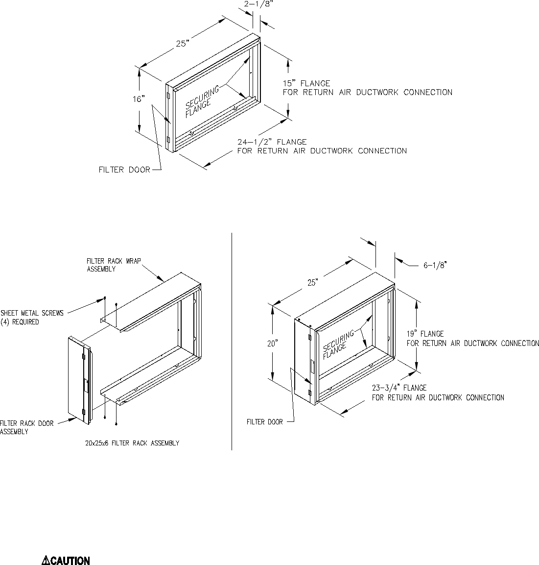
E. Air Filter Mounted External to Furnace:
On highboy furnaces, it is necessary to cut the return air opening in the side, rear casing or base,
depending upon the needs of the specific installation.
The filter rack provided with the furnace, refer to Fig. 10a & 10b, will serve as a template to scribe a mark
for the return air opening on the casing. Place the filter rack on a side casing approximately one inch up
from the bottom of the furnace and centered from side to side. Place the securing flange against the
casing when locating the return air opening. For your convenience, (4) locator knockouts have been
placed at the proper locations on both the left and right side casings.
PLEASE NOTE: While scribing the return air opening, the filter rack can be held in position by tape or
similar temporary means.
Position the open end of the filter rack so as to provide access for filter replacement. Once the filter rack
is positioned correctly, scribe a line along the inside of the securing flange on three of the sides. To scribe
a line on the fourth side (the open end), use the open-end support as a guide.
Remove the filter rack and cut the return air opening in the casing. Now the filter rack can be anchored to
the furnace with screws or pop-rivets through the securing flange of the filter rack.
16
Connect the return air plenum to the filter rack and slide the filter into place. Dimensions for adapting the
return air plenum to the filter rack are provided (See Fig. 10a & 10b).
Fig. 10a: A typical filter rack and dimensions for the OH6 furnace.
Fig. 10b: A typical filter rack and dimensions for the OH8 furnace.
: Failure to comply with minimum filter installation requirements may affect the
performance and/or void the warranty on this unit.
If a method other than Thermo Pride filter racks is selected for retention of the filter and/or use of a
different filter type is desired, refer to Table 4 below for minimum sizing guidelines for selecting filter for
the unit.
17
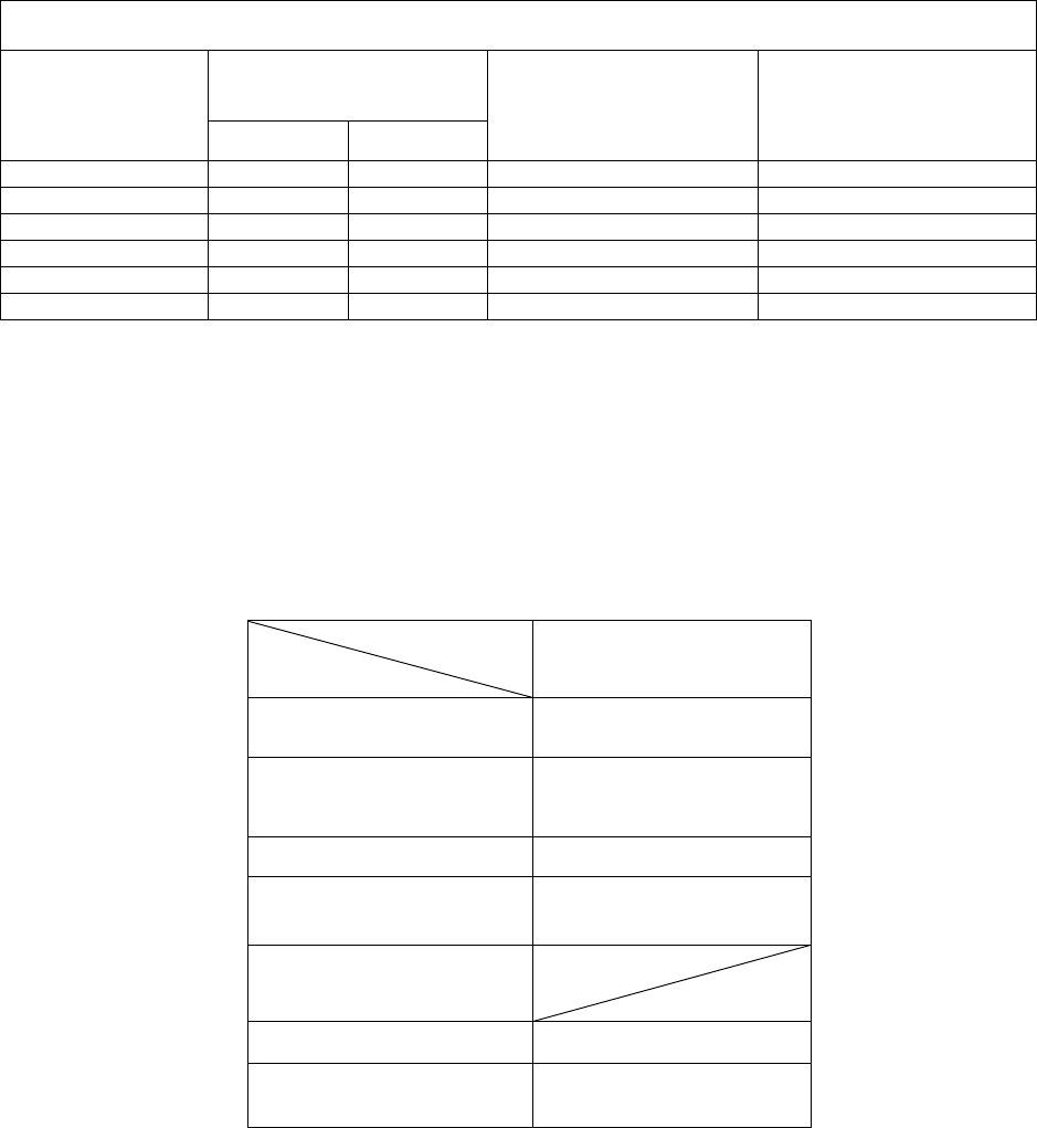
Filter Type
Maximum
Air Velocity
(ft/min)
Model Number
OH6
OH8
*Thermo Products
Supplied Permanent
600 384 in² 480 in²
Standard
Permanent
500 461 in² 576 in²
Disposable 300 768 in² 960 in²
Table 4: Minimum Required Filter Area (in square inches)
* The Thermo Products supplied filter can be cut to size to fit other filter retention systems as
long as the maximum air velocity is not exceeded.
NOTICE: Any internal stiffeners used in the filter must not be removed, although
they can be cut to size as needed.
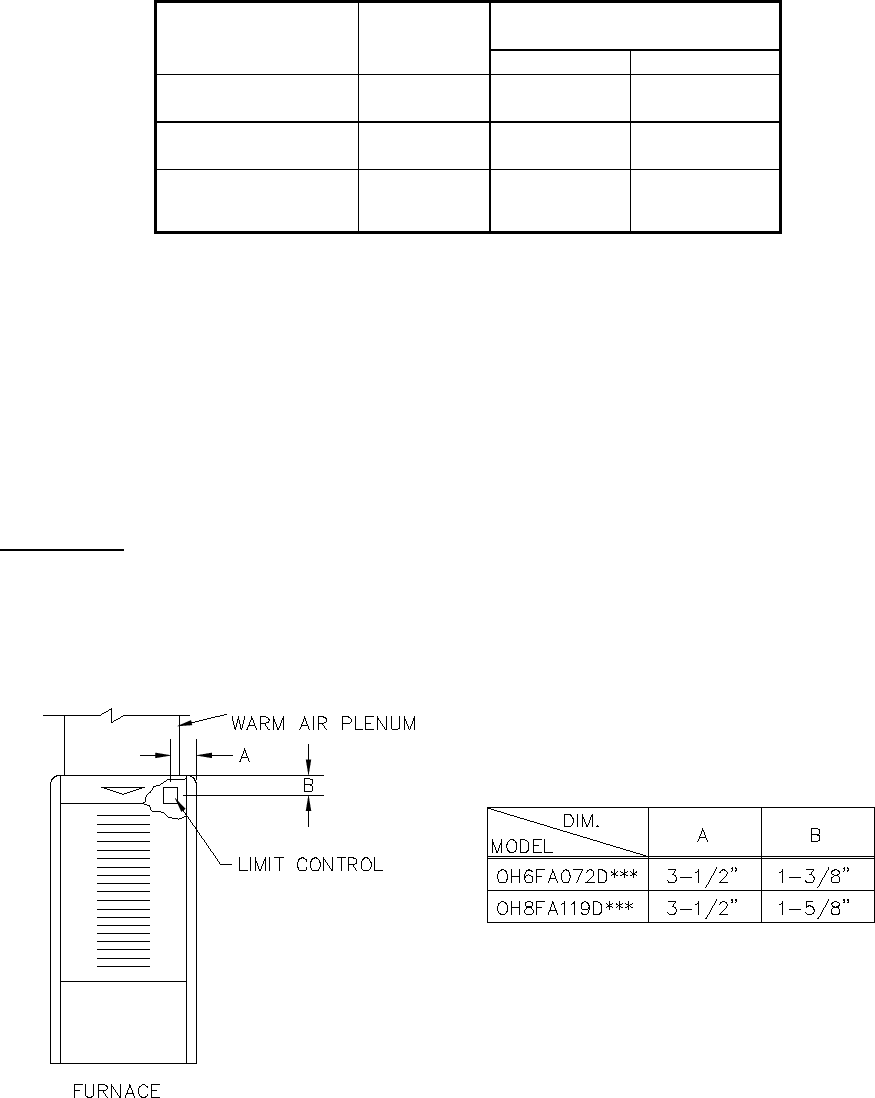
F. LIMIT POSITION AND LOCATION
WARNING: The predetermined limit locations on all of the Thermo Pride oil fired furnaces have been
tested and approved by Thermo Products, LLC. Any attempt to relocate these safety controls or replace
these safety controls with a control that is not approved, or is incompatible, may result in personal injury,
substantial property damage or death.
The unit listed in the table below must have the limit control installed at the time of unit installation.
Fig. 11: Limit location for OH6 & OH8
TABLE 5: Installation location of
the fan and limit control for each
furnace
18
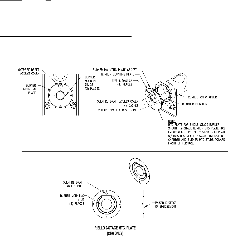
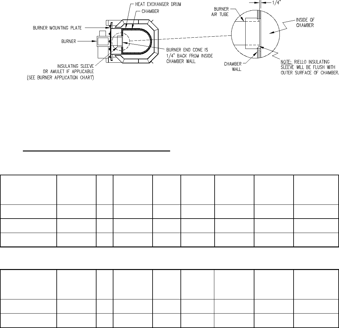
G. BURNER INSTALLATION:
NOTICE: Remove all cardboard packing from around chamber before installing burner.
The oil burner will mount on three stud mounting bolts on the lower mounting plate covering the opening
in the front of the heat exchanger. The end of the burner tube should be inserted no further than 1/4 inch
back from the inside surface of the combustion chamber. A distance further than 1/4 inch back from the
inside chamber wall may cause impingement and sooting. This unit is equipped with a chamber retainer
(refer to Fig.12). The retainer secures the chamber during shipping and helps to maintain insertion depth.
DO NOT remove this retainer when installing burner.
Fig. 12: Typical location of the over fire air tap and components in burner mounting plate area
19
Fig. 13: Burner insertion illustration (Top view)
When mounting the burner, the mounting plate (Fig. 12) must be removed to provide access to the area
in front of the combustion chamber. A fiber insulating sleeve or amulet is provided on the burner tube of
specific Thermo Pride burners.(see Fig. 13). See Thermo Pride burner application chart for type of
insulator. Do not allow the burner tube or end cone to physically touch or protrude into the chamber, as
excess heat transfer could result in destruction of the tube, end cone or both. The burner tube/end cone is
properly positioned, when the end is ¼ inch back from the inside surface of the combustion chamber wall.
DO NOT CHANGE POSITION OF THE CHAMBER!
H. BURNER SPECIFICATIONS AND APPLICATIONS:
FURNACE MODEL
THERMO
PRIDE’S
BURNER
SPEC NO.
*
INS
BECKETT
BURNER
MODEL &
TUBE
LENGTH
HEAD
STATIC
PLATE
MAXIMUM
NOZZLE
SIZE**
SHIPPED
NOZZLE SIZE
OIL
PUMP
PRESSURE
(PSIG)
OH6FA072D**B TP2501 N AFG-4.5” F3 3-5/8 0.75X80° H 0.60X80° H 120
OH6FA072D**N TP2601 S NX-4.5” FIXED N/A 0.60X70° H 0.50X70° H 150
OH8FA119D**B TP2502 N AFG-4.5” F6 2-3/4U 1.10X80° H 1.00X80° H 120
The optional BF3 or BF5 Riello flame retention oil burner can be used with OH6 and OH8.
FURNACE MODEL
THERMO
PRIDE’S
BURNER
SPEC NO.
INS
+
RIELLO
BURNER
MODEL &
TUBE
LENGTH
HEAD
STATIC
PLATE
MAXIMUM
NOZZLE
SIZE**
SHIPPED
NOZZLE SIZE
OIL
PUMP
PRESSURE
(PSIG)
OH6FA072D**R C8511325 S BF3-4.5” N/A N/A 0.70X80° H 0.60X80° H 140
OH8FA119D**R C8512317 S BF5-4.5” N/A N/A 1.00X80° H 0.85X80° H 140
Table 6: Beckett & Riello burners specifications
+ INSULATOR S = SLEEVE OR N = NONE
THE NOZZLE SIZE GIVES THE NOMINAL FLOWRATE, IN GPH, FOLLOWED BY THE SPRAY
ANGLE, IN DEGREE’S, AND THE SPRAY PATTERN, EITHER “H” FOR HOLLOW CONE OR “S”
FOR SOLID CONE. FOR EXAMPLE, A NOZZLE RATED AT 0.65 GPH @ 100 PSIG THAT PROVIDES
AN 80° SPRAY ANGLE AND A HOLLOW SPRAY PATTERN WOULD BE ABBREVIATED IN THE
TABLE AS “0.65 X 80
°
H”.
For more specific burner information, contact:
Thermo Products, LLC. P.O. Box 217, North Judson, IN 46366.
Phone 574-896-2133.
20
Table 7: Oil nozzle capacity
All rates shown achieved with 120 PSIG pump pressure for Beckett and 140 PSIG pump pressure for
Riello.
* Based on #2 domestic heating fuel oil having heating value of 140,000 BTU per gallon.
** Based on thermal efficiency of 84%-85%.
Riello 2-stage burner specifications and applications (OH6 ONLY):
MODEL
PART
OH6 2-STAGE
MTG. PLATE
PART NO. 11700
MTG. PLATE
GASKET
PART NO.
330212
**NOZZLE SIZE .70 X 45° W
NOZZLE
PART NO. 380702
OIL PUMP
PRESSURE
130 LOW
170 HIGH
BURNER G5D
BURNER
PART NO. 380529
Table 8: Riello burner application
THE NOZZLE SIZE GIVES THE NOMINAL FLOWRATE, IN GPH, FOLLOWED BY THE SPRAY
ANGLE, IN DEGREE’S, AND THE SPRAY PATTERN, EITHER “H” FOR HOLLOW CONE OR “S”
FOR SOLID CONE. FOR EXAMPLE, A NOZZLE RATED AT 0.65 GPH @ 100 PSIG THAT PROVIDES
AN 80° SPRAY ANGLE AND A HOLLOW SPRAY PATTERN WOULD BE ABBREVIATED IN THE
TABLE AS “0.65 X 80
°
H”.
** NOTE: The reason the Riello burner nozzle sizes are smaller than the standard Thermo Pride burner
nozzles is that pre-set pump pressures are higher, therefore achieving the same firing rate with a smaller
nozzle.
OIL NOZZLE CAPACITY CHART
UNITS
NOZZLE SIZE
(GPH) EQUIVALENT HEAT
INPUT RATE*
(BTU/HR)
EFFECTIVE HEATING
CAPACITY**
(BTU/HR)
Beckett Riello
OH6FA060D***
.50
.50
70,000
60,000
OH6FA072D***
.60
.60
85,000
73,000
OH6FA090D***
.75
.70
106,250
90,000
OH8FA101D***
.85
.75
119,000
101,000
OH8FA119D***
1.00
.85
140,000
119,000
OH8FA132D***
1.10
1.00
156,250
132,000
21
For more specific burner information, specifications or service information, reference the training manual
enclosed with each Riello burner or contact:
Riello Corporation of America,
5 Pond Park Road Hingham, Massachusetts 02043
Phone: (617) 749-8292
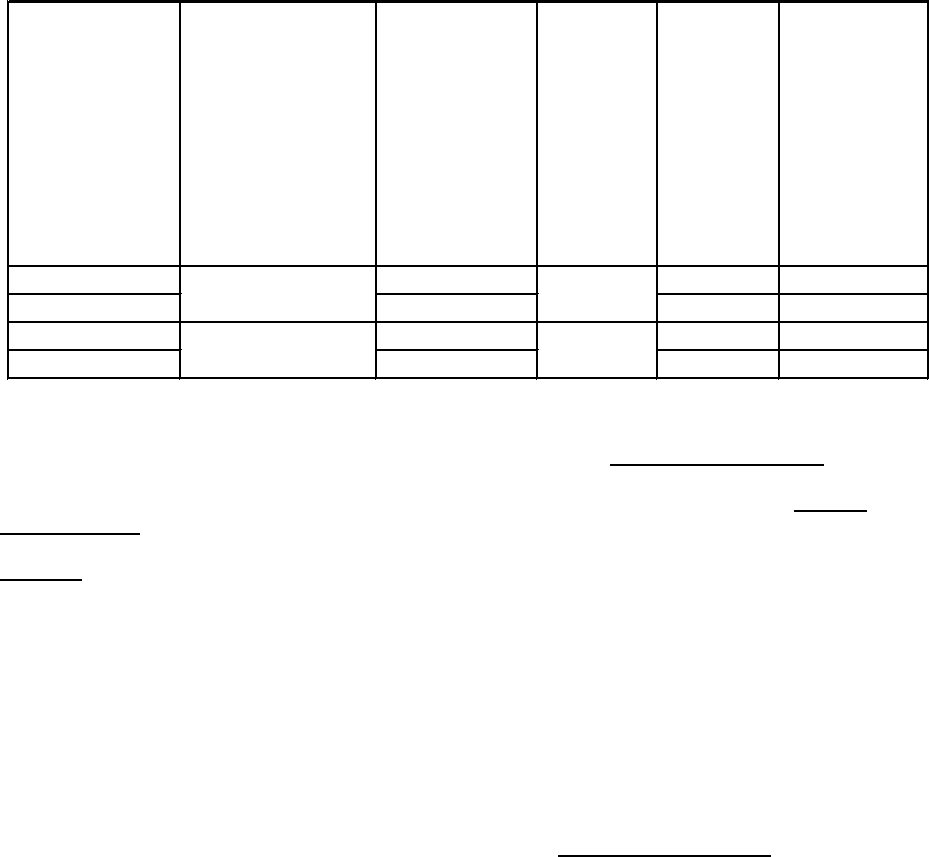
2 STAGE FIRING RATES
CAPACITY
FIRING
RATE
NOZZLE SIZE
Riello
INPUT RATE*
(BTU/HR)
EFFECTIVE**
HEATING
CAPACITY
HIGH CAPACITY
HIGH FIRE
.70 X 45° W
106,250/170psi
90,000
LOW FIRE
85,000/130psi
74,000
LOW CAPACITY
HIGH FIRE
.50 X 45° W
85,000/170psi
74,000
LOW FIRE
70,000/130psi
60,000
Table 9: Riello 2-stage firing rates
* Based on #2 domestic heating fuel oil having heating value of 140,000 BTU per gallon.
** Based on thermal efficiency of 84%-85%.
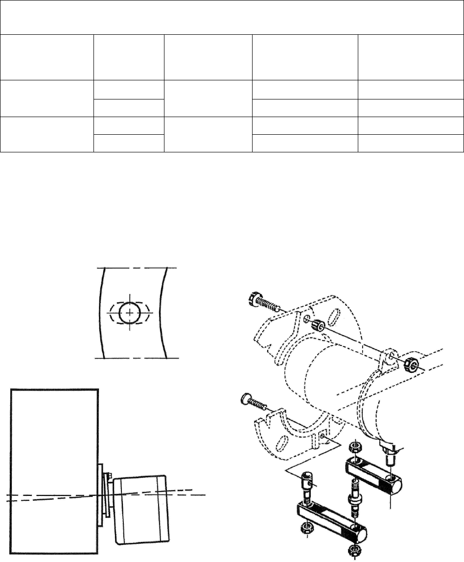
MOUNTING THE 2-STAGE RIELLO BURNER:
It is necessary that the insulation gasket be placed between the mounting plate and the burner flange.
The insulating gasket has six holes, which, if necessary, can be modified as shown. (see figure 14-1)
Figure 14-1: Burner gasket and mounting Figure 14-2: Burner fixing and hinge assembly

22
Verify that the installed burner is lightly leaned towards the button. (See figure 14-1) The burner is
designed to allow entry of the flexible oil-lines on either side of the burner.
I. OIL TANK AND PIPING:
: All local codes and ordinances take precedence with regard to selection and
installation of oil storage tank and oil supply (and return) lines. In the absence of local codes, all
tanks and lines must be selected and installed according to the instructions in this manual and
the Standard for the Installation of Oil-Burning Equipment, NFPA 31-1997, or the latest edition.
1. The use of black steel pipe and malleable iron fittings is recommended for all fuel oil service
lines. Never use galvanized steel piping or fittings for any fuel oil lines.
2. Where practical, provide rigid supports for the piping.
3. If the piping size in a run must be reduced, use reducing couplings only. Avoid the use of
reducing bushings.
4. Remove all pipe thread burrs and inspect the pipe for dirt or other foreign material prior to
connecting. If present, remove any deposits in the piping and discard any excessively corroded
piping.
5. A readily accessible, design-certified, manual oil shutoff valve, with a non-displaceable rotor
member, shall be installed in the fuel oil supply piping within 6 feet of the appliance.
6. A pipe union, or flanged connection, shall be provided downstream from the manual oil shutoff
valve to permit removal of the appliance oil pump. Pipe unions must be the ground joint type or
flanged-jointed using a gasket resistant to the corrosive action of fuel oils.
7. Pipe dope or thread sealant design-certified to be resistant to the action of fuel oils should be
used on all threaded joints. Thread sealant should only be applied to the male member of a
joint. The first two threads on the end of the male member of each pipe joint should be clean
and free from thread sealant.
8. Connection of the oil supply piping to the appliance should be made from the left-hand side of
the burner, facing the burner compartment cover.
9. When tubing is to be used for fuel oil supply lines, use of continuous runs of heavy wall copper
tubing is recommended. Avoid running tubing against any type of heating unit and across
ceiling or floor joists. If possible, install the tubing under the floor.
10. Where tubing is used for fuel oil supply lines, insure the tubing contains no kinks, sharp bends,
or collapsed regions where the inside cross-sectional area of the tube is greatly reduced. These
will excessively reduce the flow of oil.
11. Flared fittings should be used at all tube joints, when tubing is used for fuel supply lines. Do
not use compression fittings. Avoid the use of tube fittings in inaccessible locations.
Burners are equipped with a single-stage, fuel pump. This type of fuel pump, when connected with a
supply line only, is satisfactory where the fuel supply is level with, or above the burner thus permitting
gravity flow of oil to the burner. If the tank is above the burner, and gravity oil feed to the burner is
permitted, a single line system may be used. The line should have a gradual slope downward of
approximately 1/2 inch per foot, or more, from the tank to a point directly below where it is connected to

23
the pump. Pitching the line upward toward the tank will help prevent the formation of air pockets in the
line.
NOTICE: An oil safety valve or a delayed-action, solenoid valve should be
installed in the oil supply line of all gravity-fed systems.
When the oil tank is located below the level of the burner, it is necessary to “lift” the oil to the burner. A
return line should be connected between the fuel pump and tank. This requires insertion of the "by-pass"
plug into the fuel pump. If the lift (vertical distance between the supply line inlet and the burner) exceeds
approximately 8 feet, a two-stage pump should be installed with a return line. When a return line is used
with either single or two-stage pumps, in-line air is automatically returned to the tank, making the oil pump
and lines self-purging.
Underground tanks should be located outside the building. Installation of above ground tanks is permitted
inside buildings, under certain conditions, as well as outside. Consult the Standard for Installation of Oil-
Burning Equipment for restrictions. If permitted, connect the burner oil supply line near the base of the
tank, opposite of the fill end. Connection at this point tends to flush older oil through and out of the tank.
This helps to prevent the accumulation of rainwater and condensed water vapor in the tank, which can
cause the tank to corrode.
If the oil supplier does not already use oil additives, it is recommended that additives be used to emulsify
any water accumulation in the oil.
J. OIL FILTER:
It is strongly recommended that an oil filter assembly be installed in the oil supply line to the unit. This
filter should have the capacity to trap a 40-50 micron particle.
The filter cartridge should be replaced at least once a year. The filter body should be thoroughly cleaned
before installing a new cartridge.
K. ELECTRICAL WIRIING:
: This appliance must be grounded in accordance with local codes, or in the absence
of local codes, with the National Electrical Code, ANSI/NFPA 70-1999, or the latest edition.
All wiring must conform to the provisions of local codes or, in the absence of local codes, with the
provisions of the National Electrical Code, ANSI/NFPA 70-1999, or the latest edition, and this instruction
manual.
This appliance requires 120 VAC, 60 Hz, single-phase power. Refer to Table 10 for typical electrical
current draws of the individual appliance motors, recommended sizes for over-current and short circuit
devices, and minimum recommended field wiring sizes. Electrical service must be brought to the unit from
a circuit breaker, or fused disconnect switch, in accordance with local codes. The disconnecting switch
must be located reasonably close to and within sight of the unit. Care must be taken to ensure correct
polarity when wiring the furnace.
Two-wire service, one “hot” lead (L1) and a common (L2), plus a ground conductor, is required. Connect
power to the appliance control system at the junction box in the burner compartment. (A knockout fitting is
provided on the exterior of the burner compartment for this purpose.) A ground wire must be connected to
the grounding wire in the junction box.
Field wiring of power circuits to the appliance should consist of copper conductors rated for at least
15 amp service with an insulation temperature rating of at least 75°C temperature rise. Depending upon
code requirements, rigid or flexible conduit is recommended, and may be required. Connect the electric
power supply as shown in the wiring diagram located on the inside of the front door.
24
Typically, control wiring between the appliance and the indoor thermostat, and if used, electronic air
cleaner or humidifier, will be required. Field wiring of control circuits should consist of copper conductors
rated for at least 15 amp service with an insulation temperature rating conforming to Type T wire, 35°C
temperature rise. Depending upon code requirements, rigid or flexible conduit is recommended, and may
be required. Make connections between the thermostat, and electronic air cleaner or humidifier (if used),
and the fan control module, inside the vestibule. Consult the wiring diagram for the appropriate
connection points on the thermostat and the fan control module.
Model
Potential/Frequenc
y/No. of Phases
(V/Hz/Ph)
Supply/Return
Air Blower Full
Load Current
(Amps) @ 115
VAC
Oil Burner
Assembly
Full Load
Current
(Amps) @
115 VAC
Maximum
Time Delay
Type Fuse
or Inverse
Time
Circuit
Breaker
Size
(Amps)
Minimum
Recommende
d 75 deg. C.
Copper
Power Wiring
Size (AWG)
OH6FA072D48 7.5 PSC 15 12
OH6FA072DV5 10.1 ECM 15 12
OH8FA119D60 19.2PSC 20 12
OH8FA119DV5 19.1 ECM 20 12
120/60/1
120/60/1
2.6
2.6
Table 10: Typical Electrical Requirements
Wire size selections in Table 10 are based upon Table 310-16 of the National Electrical Code for three
copper conductors, with insulation rated for 75 degrees Celsius, contained in raceway at 30 degrees
Celsius. For other wire insulation temperature ratings and ambient conditions, refer to the National
Electrical Code for the minimum wire sizing requirements.
NOTICE: Before the unit is started, the installer and/or electrician must check the following items:
1. Check every electrical connection of “push-on” or “screw-on” type terminals to ensure that all
wires and wire connectors are firmly secured. A loose terminal can cause poor flow of electrical
power to motors. This may result in very high current draws by these components. If great
enough, high current draw will cause blown fuses, burned wires and contactor points, and pre-
mature motor failure. Each electrical connection has been factory checked, however, connections
may loosen, due to vibration, while the appliance is in transit. Please be certain that all
electrical connections remain tight.
2. Review wiring diagram for proper routing and connection of all field wiring.
3. All wiring sizes must comply with local codes or the National Electrical Code. To minimize
voltage drop to the appliance, the next larger size wire should be used when long wiring runs,
in excess of 100 ft., are employed. Refer to the wiring diagrams when wiring or servicing.
In the event a circuit breaker trips or a fuse blows as a result of the operation of this appliance, investigate
the appliance electrical system to determine the cause. Correct any electrical faults and abnormal
conditions before putting the unit back into operation. Do not put in a larger fuse and do not exceed
maximum fuse size listed on the rating label in order to temporarily “fix” the problem. The rating
label is located on the inside of the burner compartment cover.
Electronic Air Cleaner (EAC) and Humidifier Installation:
The fan timer on this unit has designated terminals to control the operation of an electronic air cleaner
and/or humidifier. These terminals provide line voltage for the control of these accessories, refer to Figure
15 on the next page. Connection between EAC and N6 provides a switched 115 vac to power an
electronic fan cleaner. The same-switched 115 vac is available between EAC and N7 and may be used
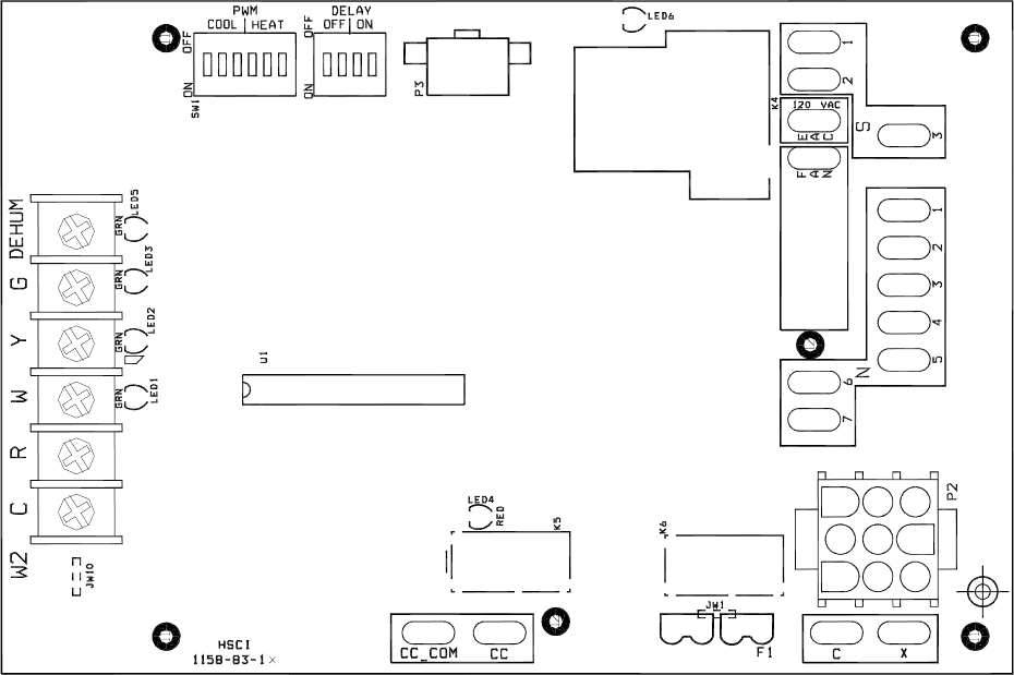
25
in conjunction with a humidistat to control a humidifier. These terminals are energized whenever the
blower is active.
Figure 15: The Fan Control Module
NOTICE: It is important to confirm that the operating voltage of the humidifier or EAC being
installed matches the output of this control. If not, a field supplied relay or transformer may be
necessary to provide the proper control and supply voltage for the accessory being installed.
Refer to the manufacturer’s instructions for the humidifier or EAC for additional information.
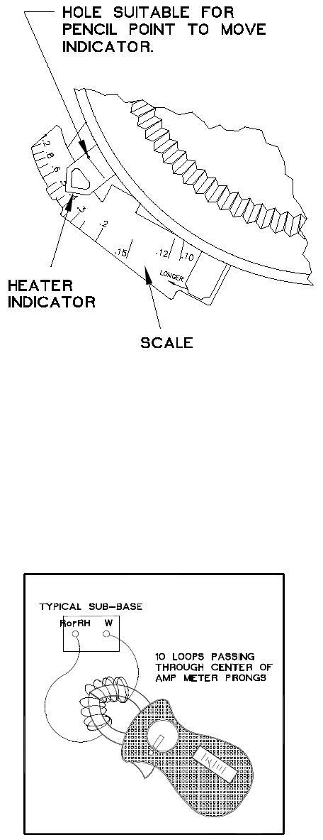
Thermostat Anticipator Setting:
Proper control of the indoor air temperature can only be achieved if the thermostat is calibrated to the
heating and/or cooling cycle. Calibration will help to produce a more constant indoor temperature by
adjusting the length of the heating/cooling cycle to fit the application. A vital consideration of this
calibration is related to the thermostat heat anticipator.
The proper thermostat heat anticipator setting is 0.1 ampere. To increase the length of the cycle, increase
the setting of the heat scale; to decrease the length of the cycle, decrease the setting of the heat scale.
Anticipators for the cooling operation are generally pre-set by the thermostat manufacturer and require no
adjustment.
Anticipators for the heating operation are of two types, pre-set and adjustable. Those that are pre-set will
not have an adjustment scale and are generally marked accordingly. Thermostat models having a scale
as shown in Figure 16 on the next page, must be adjusted to each application.
26
Figure 16: Heat Anticipator Adjustment Scale
In many cases, this setting can be found in the thermostat installation instructions. If this information is not
available, or if the correct setting is questioned, the following procedures should be followed:
Preferred method of adjustment:
Using an analog ammeter on the lowest scale, such as an Amp Check, connect the meter across
terminals “R” and “W” on the sub-base (“RH” & “W” on an isolating thermostat sub-base). If the reading is
too low to move the needle on to the measurement scale of the instrument, proceed as follows:
1. Wrap 10 loops of single strand, insulated, thermostat wire around the prongs of an ammeter, refer to
Figure 17. Set the scale to the 1 to 5 or 1 to 6 amp. scale.
Figure 17: Analog Ammeter w/ Wire Loops to Boost Reading
2. Connect the bare ends of this wire jumper across terminals “R” and “W” on the sub-base (“RH” and
“W” on an isolating thermostat sub-base). This test must be performed without the thermostat attached to
the sub-base.
3. Let the heating system operate in this position for about one minute. Read the amp meter scale.
Regardless of the value of the meter reading, divide the value by 10 (for 10 loops of wire).

27
This formula can be used to calculate the correct setting for the adjustable heat anticipator:
Ammeter reading = Anticipator Setting.
No. of wire loops
Or in this case,
_2.5 A. = 0.25 A. (Anticipator Setting)
10
4. Adjust the position of the anticipator indicator to match the calculated ammeter setting. If a slightly
longer cycle is desired, the pointer should be moved to a higher setting. Slightly shorter cycles can be
achieved by moving to a lower setting.
5. Remove the meter jumper wire and reconnect the thermostat. Check the thermostat in the heating
mode for proper operation.
If a digital ammeter is used, read the current draw directly from meter. (Steps 1 through 3 are not
required.) The meter reading is the correct anticipator setting.
L. Blower Motor Speed Selection:
: Turn off the electrical power to the unit, before attempting to change supply air
blower speed wiring.
The furnace comes from the factory with the proper cooling speed selected and the heat rise set to
approximately 66°F on mid-fire.
The heat rise is determined by the nozzle size and the switch selection on the control board located in the
vestibule compartment.
For ECM systems, switches 1, 2 & 3 of switch block SW1 (the six switch red block) are used to select the
proper blower speed. Please refer to (figure 15 and table 18).

28
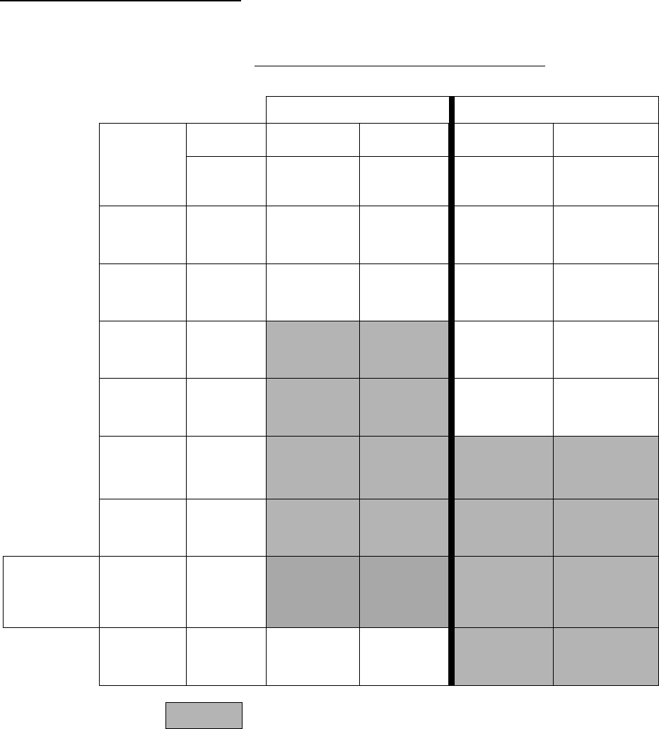
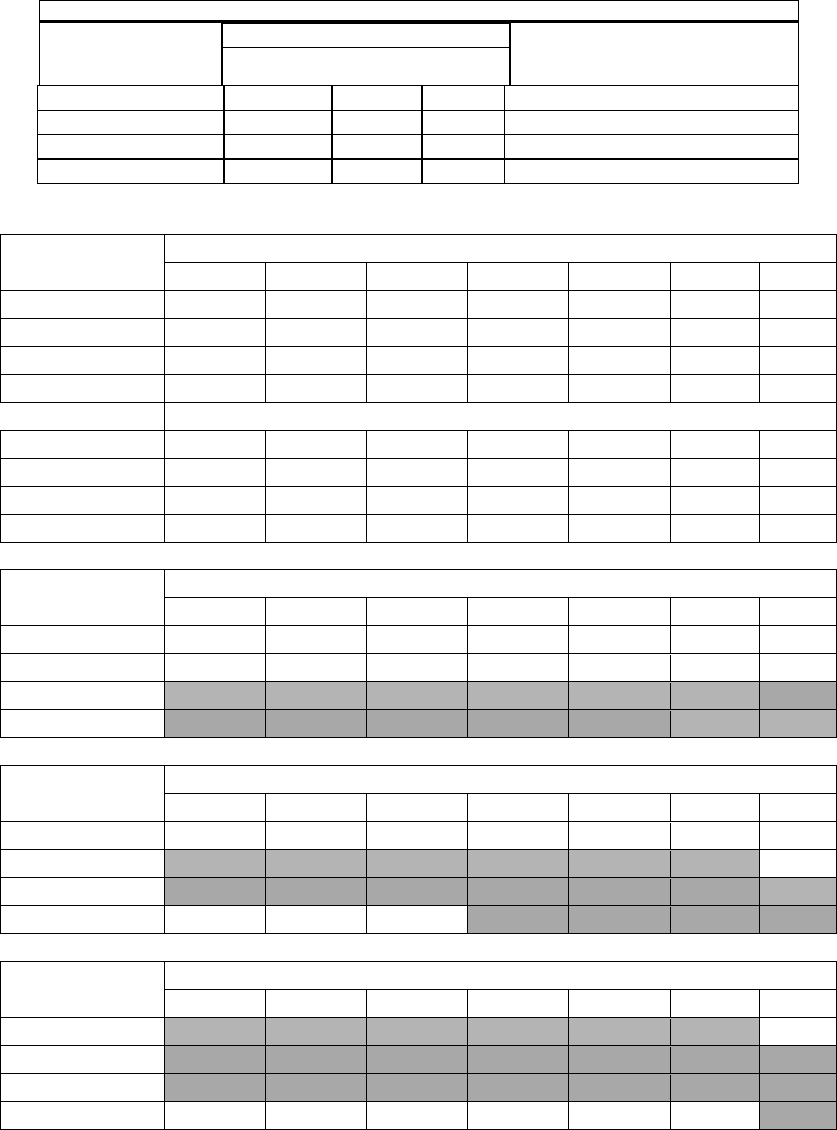
Heating Speed Set-ups
OH6FA072DV4
Furnace Motor Current
Draw (Amps/ / Watts) vs.
External Static Pressure (in W.C.)
Low Fire
Med Fire
High Fire
Static Pressure (Amps/Watts)
BTUH
60,000
72,000
90,000
Fan
Control
SW 1
Switch
Settings
Heating
CFM
Aprox. Rise
(F
0
)
Aprox. Rise
(F
0
)
Aprox. Rise
(F
0
)
0.2
0.5
3
-OFF
2
-OFF
1-OFF
740 75o
1.1/98 1.8/173
3
-OFF
2
-OFF
1-ON
812 68o 82o
1.3/114 2.1/193
3
-
OFF
2
-ON
1-OFF
883 63o 76o 1.5/129 2.4/218
Factory
SW1 Switch
Settings
3
-
OFF
2
-ON
1-ON
968 57o 69o 86o 1.7/148 2.4/223
3
-ON
2
-OFF
1-OFF
1054
63o 79o 1.9/173 2.7/246
3
-ON
2
-OFF
1-ON
1153
58o 72o 2.3/207 3.0/283
3
-ON
2
-ON
1-OFF
1267
66o 2.7/247 3.5/332
3
-ON
2
-ON
1-ON
1424
58o 3.4/315 4.3/409
= Recommended Heating Speed Setting
Figure 18-1: ECM blower motor speed chart

29
Heating Speed Set-ups
OH8FA119DV5
Furnace Motor Current
Draw (Amps / Watts) vs.
External Static Pressure (in W.C)
Low Fire
Med Fire
High Fire
BTUH
101,000
119,000
132,000
Fan
Control
SW 1
Switch
Settings
Heating
CFM
Aprox.
Rise (F
0
)
Aprox.
Rise (F
0
)
Aprox.
Rise (F
0
)
.02
.05
3-OFF
2-
OFF
1-OFF
1202 78o
1.6/146
2.5/233
3-
OFF
2-
OFF
1-ON
1315 71o 84o
1.9/174
2.7/252
3-
OFF
2-ON
1-OFF
1429 65o 77o
2.3/206
3.2/294
3-OF
F
2-ON
1-ON
1565 60o 70o 78o
2.6/242
3.6/337
Factory SW1
Switch
Settings
3-ON
2-
OFF
1-OFF
1701 55o 65o 72o
3.1/292
4.1/399
3-ON
2-
OFF
1-ON
1860
59o 66o
3.7/354
4.8/466
3-ON
2-ON
1-OFF
2041
60o
4.7/452
5.7/567
3-ON
2-ON
1-ON
2223
55o
5.9/587
7.2/719
Figure 18-1A: ECM blower motor speed chart
30
Heating Speed Set-ups ( 2 – Stage )
OH6FX072DV4
HEATING AIR FLOW / TEMPERATURE RISE
LOW CAPACITY HIGH CAPACITY
FAN
CONTROL
SW 1
SWITCH
SETTINGS
BTUH
LOW FIRE
60,000
HI FIRE
72,000
LOW FIRE
72,000
HI FIRE
90,000
HEATING
CFM
APPROX.
CFM/RISE
(ºF)
APPROX.
CFM/RISE
(ºF)
APPROX.
CFM/RISE
(ºF)
APPROX.
CFM/RISE
(ºF)
3 – OFF
2 – OFF
1 – OFF
740 592 / 94º 740 / 90º 592 / 113º 740 / 113º
3 – OFF
2 – OFF
1 – ON
812 650 / 85º 812 / 82º 650 / 103º 812 / 103º
3 – OFF
2 – ON
1 – OFF
883 706 / 79º 883 / 75º 706 / 94º 883 / 94º
3 – OFF
2 – ON
1 – ON
968 744 / 72º 968 / 69º 774 / 86º 968 / 86º
3 – ON
2 – OFF
1 – OFF
1054 843 / 66º 1054 / 63º 843 / 79º 1054 / 79º
3 – ON
2 – OFF
1 – ON
1153 922 / 60º 1153 / 58º 922 / 72º 1153 / 72º
FACTORY
SW1
SWITCH
SETTINGS
3 – ON
2 – ON
1 – OFF
1267 1013 / 55º 1267 / 53º 1013 / 66º 1267 / 66º
3 – ON
2 – ON
1 – ON
1424 1139 / 49º 1424 / 47º 1139 / 59º 1424 / 59º
= Recommended heating speed setting
Figure 18-2: ECM 2-stage blower motor speed chart

31
Cooling Speed Set-ups
OH6F*072DV4
Furnace Motor Current
Draw (Amps / Watts) vs.
External Static Pressure (in W.C)
Air Flow
Static Pressure (Amps/Watts)
Fan
Control
SW 1
Switch
Settings
Clg. Tonage
Cool
Continuous
0.2
0.5
6-OFF
5-
OFF
4-OFF
2 799 500 1.2/109 2.1/186
6-
OFF
5-
OFF
4-ON
2.5 1017 508 1.8/160 2.5/230
6-
OFF
5-ON
4-OFF
3 1210 605 2.4/220 3.3/308
6-
OFF
5-ON
4-ON
3.5 1404 702 3.2/305 4.2/409
Factory
SW1
Switch
Settings
6-ON
5-
OFF
4-OFF
4 1622 799 4.6/443 5.7/560
NOTE: All information is approximate. Results will vary by installation.
Figure 18-3: Cooling blower motor speed chart

32
Cooling Speed Set-ups
OH8FA119DV5
Furnace Motor Current
Draw (Amps/Watts) vs.
External Static Pressure (in W.C.)
Air Flow
Fan
Control
SW 1
Switch
Settings
Clg.
Tonnage
Cool
Continuous
Dehum
.02
.05
6-OFF
5-OFF
4-OFF
2 800 500
557
1.0/89
1.8/161
6-OFF
5-OFF
4-ON
2.5 1018 509
703
1.4/121
2.1/192
6-
OFF
5-ON
4-OFF
3 1212 606
848
1.8/159
2.6/231
6-
OFF
5-ON
4-ON
3.5 1406 703
994
2.3/203
3.1/290
Factory
SW1
Switch
Settings
6-ON
5-OFF
4-OFF
4 1624 800
1139
3.0/278
4.0/378
6-ON
5-OFF
4-ON
4.5 1818 897
1285
3.8/353
5.0/475
6-ON
5-ON
4-OFF
5 2012 994
1406
4.8/456
6.0/582
6-ON
5-ON
4-ON
5.5 2230 1115
1551
6.1/593
7.4/729
NOTE: All information is approximate. Results will vary by installation.
Figure 18-3A: Cooling blower motor speed chart
33
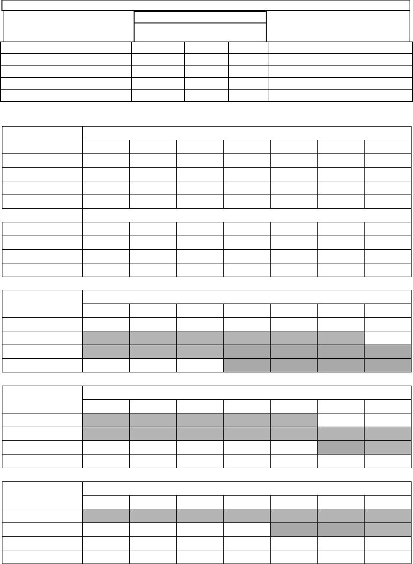
For PSC systems, the ½ hp motor is equipped with 4 speeds. The unit is set for mid-fire temp rise @
66ºF. See table for proper blower motor set up:
OH6FA072D48
ALTERATIONS REQ’D FOR A/C @ DESIGN EXTERNAL STATIC PRESSURE
COOLING UNIT
HTG Speed by Input
Low Mid High
Fire Fire Fire
Recommended CLG Speed
24,000
Low
ML
MH
Low
30,000
Low
ML
MH
Med Low
36,000
Low
ML
MH
Med High
42,000
Low
ML
MH
Med High
48,000
Low
ML
MH
High
Figure 19A: Heating speed by input
Speed Tap\ Static
Pressure
Furnace Airflow (CFM) vs. External Static pressure (in. WC.)
0.1
0.2
0.3
0.4
0.5
0.6
0.7
Low
930
915
912
910
822
774
730
ML
1155
1152
1130
1126
1085
1042
920
MH
1442
1432
1418
1382
1334
1293
1230
High
1802
1762
1705
1635
1569
1493
1428
Furnace Motor Current Draw (Amps) vs. External Static pressure (in. WC.)
Low
3.3
3.1
3.0
2.9
2.6
2.5
2.4
ML
4.2
4.0
3.9
3.7
3.6
3.3
3.0
MH
5.4
5.2
5.0
4.7
4.4
4.2
4.0
High
6.6
6.4
6.0
5.7
5.5
5.2
5.0
Speed Tap\ Static
Pressure
High Fire Temperature Rise vs. External Static pressure (in. WC.)
0.1
0.2
0.3
0.4
0.5
0.6
0.7
Low
90
91
91
92
101
108
114
ML
72
72
74
74
77
80
91
MH
58
58
59
60
62
64
68
High
46
47
49
51
53
56
58
Speed Tap\ Static
Pressure
Mid Fire Temperature Rise vs. External Static pressure (in. WC.)
0.1
0.2
0.3
0.4
0.5
0.6
0.7
Low
72
73
73
73
81
86
91
ML
58
58
59
59
61
64
72
MH
46
47
47
48
50
52
54
High
37
38
39
41
42
45
47
Speed Tap\ Static
Pressure
Low Fire Temperature Rise vs. External Static pressure (in. WC.)
0.1
0.2
0.3
0.4
0.5
0.6
0.7
Low
60
61
61
61
68
72
76
ML
48
48
49
49
51
53
60
MH
39
39
39
40
42
43
45
High
31
32
33
34
35
37
39
34
OH8FA119D60
ALTERATIONS REQ’D FOR A/C @ DESIGN EXTERNAL STATIC PRESSURE
COOLING UNIT
HTG Speed by Input
Low Mid High
Fire Fire Fire
Recommended CLG Speed
36,000
L/ML
ML/MH
MH/H
Low (L)
42,000
L/ML
ML/MH
MH/H
Med Low (ML)
48,000
L/ML
ML/MH
MH/H
Med High (MH)
60,000
L/ML
ML/MH
MH/H
High (H)
Figure 19B: Heating speed by input
Speed vs. color code for PSC Motor:
Low = Red
Med-Low = Blue
Med-High = Yellow
High = Black
Speed Tap\ Static
Pressure
Furnace Airflow (CFM) vs. External Static pressure (in. WC.)
0.1
0.2
0.3
0.4
0.5
0.6
0.7
Low
1254
1254
1251
1246
1221
1189
1126
ML
1473
1464
1460
1437
1415
1377
1329
MH
1733
1731
1718
1705
1686
1660
1627
High
2300
2243
2224
2166
2099
2048
1754
Furnace Motor Current Draw (Amps)/Watts vs. External Static pressure (in. WC.)
Low
6.6/648
6.6/648
6.4/639
6.2/630
6.0/612
5.8/592
5.4/565
ML
7.6/772
7.2/739
7.1/730
6.8/704
6.6/683
6.3/661
6.1/641
MH
9.0/908
9.0/905
8.7/888
8.5/871
8.3/842
8.0/818
7.7/796
High
12.5/1270
11.7/1200
11.2/1150
10.7/1110
10.2/1060
9.7/1020
9.2/969
Speed Tap\ Static
Pressure
High Fire Temperature Rise vs. External Static pressure (in. WC.)
0.1
0.2
0.3
0.4
0.5
0.6
0.7
Low
98
98
98
99
101
103
109
ML
83
84
84
86
87
89
93
MH
71
71
72
72
73
74
76
High
53
55
55
57
59
60
70
Speed Tap\ Static
Pressure
Mid Fire Temperature Rise vs. External Static pressure (in. WC.)
0.1
0.2
0.3
0.4
0.5
0.6
0.7
Low
88
88
88
89
90
93
98
ML
75
75
75
77
78
80
83
MH
64
64
64
65
65
66
68
High
48
49
50
51
52
54
63
Speed Tap\ Static
Pressure
Low Fire Temperature Rise vs. External Static pressure (in. WC.)
0.1
0.2
0.3
0.4
0.5
0.6
0.7
Low
75
75
75
75
77
79
83
ML
64
64
64
65
66
68
70
MH
54
54
55
55
56
56
58
High
41
42
42
43
45
46
53

35
M. BLOWER CONTROLLER INFORMATION FOR PSC MOTOR
(Note: for ECM blower controller information see: ECM Operation Manual document # Mo-440)
TERMINAL DEFINITIONS & FIELD WIRING
Burner Harness Connector P1
Pin 1- Limit switch connector.
Pin 2- 120 VAC Line connection.
Pin 3- Burner pilot contact.
Pin 4&5- 120 VAC Neutral connections.
Pin 6- Burner pilot contact.
Pin 7&8- From oil primary control.
Pin 9- Limit Switch Input (LSI).
Field Wiring to Burner
Harness Wires
Beckett Connections
Riello Connections
Thermostat / Humidistat connections
“C” Common / ground
“W” Thermostat call for heat
“R” 24 VAC to thermostat
“G” Thermostat call for fan
“Y” Thermostat call for cool
“DEHUM” Humidistat call for dehumidification (TXV systems ONLY)
Male quick connect terminals.
“S1-3” 120 VAC Hot
“N1-7” 120 VAC Neutral
“EAC” Electronic Air Cleaner (120 VAC) connection
“FAN” Fan On Signal
“X” 24 VAC from transformer
“C” 24 VAC common from transformer
“CC” Compressor Contactor
“CC_COM” Compressor Contactor Common
“LOW” Continuous Blower Speed
“HEAT” Blower heat speed tap
“COOL” Blower cool speed tap
Pilot (Tstat) Neutral Line
Yellow Wires
White
Red
T-T terminals
White
Black
T-stat terminals
White
Black

36
A. Inputs
Power supplies
Line voltage is applied between the “S1” and “N1” quick connect terminals. 24 VAC Class II
Transformer secondary voltage supplied to X and C
Limit switch
The 120 VAC optically isolated limit switch input is connected on pin P2-1 & 9. Refer to the Heat
Mode section for the control operation.
Thermostat call for heat “W”
24 VAC thermostat input. A call for heat is recognized when the thermostat connects “W” to “R”. This
input has an indicator LED that will light when the control receives a call for heat. Refer to the Heat
Mode section for the control operation.
Thermostat call for cool, “Y”
24 VAC thermostat input. A call for cooling is recognized when the thermostat connects “Y” to “R”. This
input has an indicator LED that will light when the control receives a call for cooling. Refer to the Cool
Mode section for the control operation.
Thermostat call for dehumidification “DEHUM”
24 VAC thermostat input. A call for dehumidification is recognized when the humidistat connects
“DEHUM” to “R”. This input has an indicator that will light when the control receives a call for
dehumidification. Refer to the Cool Mode section for the control operation.
Thermostat call for fan “G”
24 VAC thermostat input. A call for fan is recognized when the thermostat connects “G” to “R”. This
input has an indicator LED in that will light when the control receives a call for fan. Refer to the Fan
Mode section for the control operation.
B. Outputs
PSC Control
The control shall control a five-speed indoor blower motor. Rating shall be 10 FLA, 30 LRA @ 120
VAC. Connections are made via 0.250 x 0.032” male quick connect terminals labeled “HEAT”,
“COOL”, and “LOW”. “HEAT” is energized when the heat speed blower is to run. “COOL” is energized
when the Cool speed blower is to run. “LOW” is energized during a call for fan is received or a call for
dehumidification is received.
Oil Burner
Control
The control provides dedicated contacts to operate the T-T input of an oil primary control.
Rating shall be class 2 – 24 VAC pilot duty @ 24 VAC (<200mA).
Power
The switched 120 VAC power from the LIMIT switch passes through the board between Pins 1 & 2
of connector P1.
Compressor contactor
The control provides switched 24VAC to operate a compressor contactor. Rating shall be class 2 – 24
VAC pilot duty @ 24 VAC (<200mA).

37
EAC (electronic air cleaner)
The control provides a 120 VAC output for an electronic air cleaner. This output is energized whenever
the fan motor is energized (either low, heat or cool speed). Connection is made via male quick connect
terminal labeled “EAC”.
Humidifier
The control provides a 120 VAC output for a humidifier. Connections are made to a male quick
connect terminal labeled “FAN”. The control does not switch this output, it provides a pass-through
connection from P1-7 from the switched primary voltage of the Burner Module.
Status LED
A red LED is provided to indicate any thermostat input has been recognized by the microprocessor on
the control. See Diagnostic Features for a function description of operation.
Thermostat Input LEDs
Four green LEDs are placed beneath their respective thermostat connections (W, Y, G and DEHUM)
and operate whenever a call is present. See Diagnostic Features for a function description of
operation.
C. Operating Modes
Standby Mode
All outputs are off and the control is waiting for a thermostat demand. The thermostat inputs, and limit
switch are continuously monitored. The control initiates action when a thermostat call is received or
limit switch opens.
Fan Mode
A call for fan (“G”) is received from the thermostat. If no other mode is calling for blower operation, the
control will operate the fan relay (K4) and power the “Low” blower speed terminal. The fan mode will
be operated as long as the “G” input is calling and neither the Heat mode nor the Cool mode is calling
for blower operation. When the Heat and Cool modes call for blower operation, their respective
outputs will take precedence after their respective turn-on time delays have expired.
Cooling Mode
A call for cool (“Y”) is received from the thermostat. If the heat mode is not active or the anti-short
cycle delay is not in effect, the control will energize the “CC” terminal and after a 10 second power
demand conservation delay energizes the “COOL” speed blower terminal.
When the call for cool is satisfied, the “CC” terminal is de-energized and the cooling off delay of 45
seconds is started. Forty-five seconds later the “COOL” speed blower terminal is de-energized and
the control reverts to Standby Mode.
Dehumidification Operation
If a call for dehumidification is received while the Cool Mode is active, blower speeds will be reduced.
The PSC “COOL” blower speed terminal (1158-100 model only) will be de-energized and “Low” blower
speed will be energized.
Anti-Short Cycle Operation
To prevent compressor short cycling, a call for cooling will be ignored for four minutes after the
termination of any cooling call. The anti-short cycle delay is also in effect at power-up.

38
Heat Mode
When a call for heat (“W”) is received from the thermostat, if the “Cool” mode is not already active, the
“T-T” terminal is energized and the blower on delay is started. The on-off pattern of DIP switch SW2
(positions 1 and 2) select one of four blower on delay values (see Table 11). When the delay time has
elapsed, the “HEAT” blower speed is energized. The control remains in steady heat mode until the
thermostat is satisfied. When the call for heat signal is removed, the “T-T” terminal is de-energized and
the blower off delay is started. The on-off pattern of DIP switch SW2 (positions 3 and 4) select one of
four blower off delay values (see Table 11). When the delay time has elapsed, the “HEAT” blower
speed terminal is de-energized.
DIP SWITCH 2 SECTION STATE
BLOWER DELAY TIMES
1 2 3 4
Counter Flow
ON - SEC
ON - SEC OFF - MIN
OFF OFF 15 30
ON OFF 24 60
OFF ON 36 120
ON ON 48 240
OFF OFF 2
ON OFF 4
OFF ON 6
ON ON 8
Table 11: ON and OFF Blower Delay Time Switch Settings
Motor Blower Speed
Three interconnected blower speed outputs are provided. A “G” call for fan will provide power to the
LOW speed tap only. A “W” heat call will provide power to the Heat speed tap only. A “Y” cooling call
will provide power to the Cool speed tap only.
In the case of thermostat calls for “Y” and “W” together, blower speed selection will be determined by
the input that was first initiated. In the case where the control is in a cooling mode with both “Y” and
“W” inputs energized and then the “Y” input is removed, the cooling blower off time will be executed
prior to the control switching into a heating mode. In the case where the control is in a heating mode
with both “Y” and “W” inputs energized and then the “W” input is removed, the heating blower off time
will be executed prior to the control switching into a cooling mode. In the case where a call for fan “G”
already exists and either a “W” or a “Y” call is initiated, the blower speed will switch to the respective
“W” or a “Y” speed following the blower on delay for that call.
The speed taps are interconnected and interlocked, only one speed may be powered at any one time.
When a speed is to be operated, the speed select relays are operated to select the path to the motor
tap and then the enable relay is operated to switch the operating power to the selected motor speed
tap. If the speed of the running motor is to be changed, first the enable relay removes power from the
motor, the new speed is selected and then power is restored to the motor.
Blower On and Off Delays
Four Heat blower on and four blower off delays are selected by two dip switches for each function.
Refer to Table 11 for specific delay values.
39
ECM & PSC TROUBLE SHOOTING
DIAGNOSTIC FEATURES
The control board is equipped with 4 green Input Status LEDs and 1 red Board Status LED. These are
intended to provide a quick view into furnace performance without requiring a voltmeter.
The green Input Status LEDs are driven by the “Y”, “W”, “G”, and “DEHUM” inputs and are located
directly below those inputs. They will light to indicate the presence of these signals.
The red Board Status LED has two functions:
It will light when the board recognizes a valid input signal and will stay lit until all valid signals are
removed. This is intended to show that the board is functioning and able to respond to input signals.
It will flash rapidly while 120VAC is missing from the LIMIT switch. This is intended to give a quick
visual indication of the High Limit switch.

40
N. STARTUP PROCEDURES:
A. Heating System
1. Initial Startup:
: Turn off power to furnace. Before the oil piping system is placed into service, it must
have been leak tested by a qualified heating contractor.
: For initial start-up of the appliance after installation, it may be necessary to purge the
air out of the oil line. A qualified heating contractor should do this.
Review the following items before the initial startup. It may be helpful to review the Sequence of
Operations in Section VIII of this manual, also.
a. Check all wiring for loose connections and proper hook-up. Refer to the connection diagram.
b. Leak test all field oil piping connections. Generally, this will involve pressurizing the oil piping
with air while being careful to isolate the oil tank at high test pressures. A qualified heating
contractor should perform this service.
c. Check to see that the vent terminal is correctly installed and the terminal openings are clear
and free from blockage.
d. Make sure the air filter is in place and relatively clean of dirt and debris.
e. Make sure the thermostat is set in the heating mode of operation.
Operating Instructions:
i. STOP! Read the safety information above.
ii. Set the thermostat to the lowest setting.
iii. Turn off all electric power to the appliance.
iv. This appliance is equipped with an ignition system that automatically lights the
burner. Do not try to light the burner by hand.
v. Rotate the manual oil shutoff valve to the “ON” position.
vi. Turn on the electric power to the appliance.
vii. Set the thermostat to the desired setting.
viii. If the appliance will not operate, call your qualified service technician or oil supplier.
For Your Safety Read Before Operating:
: If you do not follow these instructions exactly, a fire or
explosion may result causing property damage, personal injury or loss of life.
• This appliance does not have a pilot light. It is equipped with an ignition system that
automatically lights the burner. Do not attempt to light the burner by hand.
• Do not use this appliance if any part has been under water. Immediately call a qualified
service technician to inspect the appliance and to replace any part of the control system
and any oil control that has been under water.

41
To Turn Off Oil to Appliance:
i. Set the thermostat to the lowest setting and set the operating mode switch to “OFF”.
ii. If service is to be performed, turn off the electrical power to the appliance.
iii. Turn the manual oil shutoff valve to the “OFF” position.
2. Adjustment of Burner Combustion:
: Maximum gross stack temperature must not exceed 550°F (288°C) under any
circumstances.
: Do not run the oil pump dry for more than five minutes, as irreparable damage may
result.
NOTICE: Read the burner operation and service instructions, Model AFG Oil
Burner Instruction Manual, before continuing.
To initially adjust and successfully service the oil burner in the appliance heating section, the following
test instruments are required:
• A smoke density measuring and rating device,
• A carbon-dioxide (CO2) or oxygen (O2) analyzer,
• A flue gas temperature measuring device (e.g., thermocouple or thermister probe with readout
device),
• An analog or digital multimeter, and
• An oil pressure gauge capable of reading 0-150 PSIG.
To initially fire the oil burner, proceed in the following manner:
a. Turn the disconnecting switch, which provides power to the appliance, to the "OFF" position.
b. Set the room thermostat above room temperature.
c. Verify the oil tank is filled with sufficient fuel oil to operate the appliance.
d. Open all valves in the oil supply line to the burner.
e. Remove the burner compartment cover from the appliance.
f. Open the inspection cover on the upper mounting plate above the burner.
g. Turn the disconnecting switch to “ON”.
h. Prime the pump to remove air in the oil supply line.
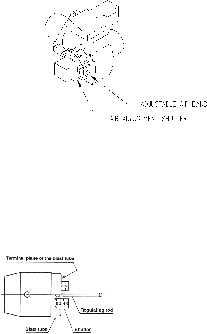
42
Figure 19: Preliminary Adjustment of Burner Air Band and Air Shutter
i. When ignition is established, make a preliminary burner air adjustment to attain a clean
combustion flame. Generally, the burner bulk air band should be about 3/16 inch open and the
opening of the burner air shutter set in the range of “2” to “7”, refer to Figure 19.
Replace the inspection cover above the burner.
j. After the appliance is warmed up to a steady state condition (about 15 minutes), the final burner
adjustment should be made using combustion instrumentation for smoke, carbon dioxide (CO2)
or excess oxygen (O2), and flue gas temperature. In order to achieve the most efficient
combustion, the following steps must be taken:
COMBUSTION HEAD SETTING FOR 2-STAGE RIELLO BURNER:
This is done when fitting the nozzle, with the blast tube removed. It depends on the output of the burner
and is carried out by rotating the regulating rod, till the terminal plane of the blast tube is level with the
set-point, as indicated in the schedule.
In figure 20 the combustion head is set for an output of
0.75 GPH at 130 psi, while the shutter is level with set-
point 2.5, as required by the above schedule.
Figure 20
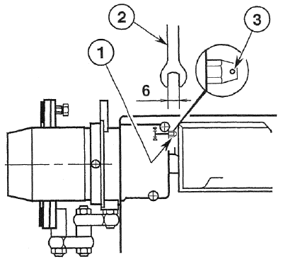
43
The setting of the fan output according to the installation
should be done only through the air damper. Should you
want to adjust the setting of the combustion head, with the
burner running, turn the rod (1) with a 6mm wrench (2) as
follows:
TURN TO THE RIGHT: (SIGN + )
In order to increase the volume of air entering the
combustion chamber and thus diminishing its pressure.
There is a reduction of CO2 and the adhesion of Figure 21
the flame to the air diffuser disc improves.
(Setting advisable for ignitions at low temperatures).
TURN TO THE LEFT: (SIGN - ) Figure 21
In order to reduce the volume of air entering the combustion chamber and thus increasing its pressure.
The CO2 improves and the adhesion of the flame to the diffuser tends to reduce. (This setting is not
advisable for ignitions at low temperatures).
In any case do not bring the combustion head setting more than one point away from that indicated in the
schedule. One set-point corresponds to 3 turns of the rod; a hole (3) at its end facilitates counting the
number of turns.
AIR DAMPER ADJUSTMENT:
The settings indicated in the schedule refer to the burner with its metal cover fitted and the combustion
chamber with “zero” depression. These regulations are purely indicative. Each installation however, has
its own unpredictable working conditions: actual nozzle output; positive or negative pressure in the
combustion-chamber, the need of excess air, etc. All these conditions may require a different air damper
setting.
It is important to take account of the fact that the air output of the fan differs according to whether
the burner has its metal cover fitted or not.
Therefore we recommended to proceed as follows:
• adjust the air damper as indicated in the schedule (3);
• mount the cover, simply by means of the upper screw;
• check smoke number;
• should it become necessary to modify the air output, remove the cover by loosening the screw,
adjust the air damper, remount the cover and finally recheck the smoke number.
The burner is provided with a hydraulic device controlled by the economizer which reduces the max.
output of oil and air by approximately 70%.
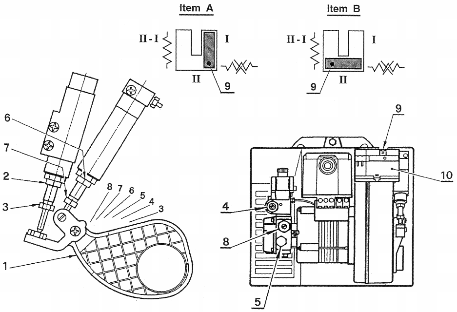
44
Figure 22
1st STAGE ADJUSTMENT:
Adjustment of air shutter: place the small plug (9) of the economizer (10) into the position I (Item A).
In this way the burner will remain permanently in the 1st stage.
Loosen the nut (2), turn the screw (3) until the air shutter (1) reaches the position desired. Then lock the
nut (2).
Pressure regulation: this is set at 130 psi at the factory. Should such pressure be reset or changed,
just turn the screw (4). The pressure gauge must be mounted in place of cap (5).
2nd STAGE ADJUSTMENT:
Adjustment of air shutter: place the small plug (9) of the economizer (10) into the position II (Item B).
In this way the burner remains permanently in the 2nd stage. Loosen the nut (6), turn the screw (7) until
the air shutter (1) reaches the position desired. Then lock the nut (6).
Pressure regulation: this is set at 170 psi at the factory. Should such pressure be reset or changed,
just turn the screw (8). The pressure gauge must be mounted in place of cap (5).
i. SMOKE: A smoke sample should be drawn from the heat exchanger flue passageway, which is
covered by the vent terminal. (Remove a large machine screw from the front face of the vent terminal
for direct access to the flue through the opening.) If the first smoke reading is zero (0), close the air
band, or shutter, on the burner until a trace smoke reading is measured.
NOTICE: To achieve proper combustion and the efficiencies listed in sales
brochures, instruments must be used to secure CO2 or O2 readings.
45
ii. CARBON DIOXIDE (CO2) OR OXYGEN (O2): Take a CO2 sample from flue passageway. It is
possible to achieve readings of up to 14% CO2 (or 2% O2 ), but it is better to have a slightly lower
CO2 (or higher O2) reading with zero smoke measured. To achieve a lower CO2 reading, open the air
band, or shutter, on the burner until zero smoke is measured.
For example, if a 13% CO2 (or 3.5% O2) is recorded at a trace of smoke, open the air shutter until zero
smoke is measured with a 12% CO2 (or 4.5% O2).
Adjustment of the burner to achieve a slightly lower CO2 reading is recommended, although it slightly
reduces combustion efficiency, to keep the heating system within normal operating conditions though
external conditions may vary. Some “out-of-spec” conditions which may adversely affect burner
performance are, low oil supply temperature, dirty (contaminated) oil, low heating content (BTU/gal) oil,
cold heat exchanger surfaces, and downdraft conditions. By adjusting the burner in this manner, an
operational tolerance is established allowing the burner to function well, even under less than ideal
conditions. This results in less service and maintenance during a heating season.
iii. FLUE GAS TEMPERATURE: The flue gas temperature will vary to some extent depending on the
heat input rate, duct design, and the amount of air flow across the heat exchanger. The suggested
minimum net flue gas temperature is 350ºF, and the maximum gross flue gas temperature is 500ºF.
The lower the flue gas temperature, the higher the heating efficiency. However, stack temperatures
under 350ºF may result in condensation of water vapor in the flue gases, which in turn promotes
corrosion of the heat exchanger.
iv. TEMPERATURE RISE: Temperature rise is equal to the supply air temperature minus return air
temperature. Under steady state operating conditions, the temperature rise across the heating section
should be approximately 66ºF. A higher temperature rise will slightly lower the heating efficiency. A
lower temperature rise will slightly raise efficiency, but may cause condensation.
The supply air temperature should be measured in the supply air trunkline approximately 12 inches
downstream of the supply air outlet of the appliance.
NOTICE: Minimum temperature rise is 51ºF.; maximum temperature rise is 81ºF.
Notice: Minimum return air temperature is 55°F
k. After final adjustments are completed, tighten all screws to fix the positions of the burner air band.
l. Check for the presence of oil leaks. Correct any oil leaks found.
m. Reassemble the burner compartment cover.
n. Start and stop the unit several times while checking for proper ignition of the burner. The flame
should ignite and stabilize without any significant rumbles or pulsations.
3. Adjustment Of Heat Input Rate:
This appliance was shipped from the factory with one, fixed, main burner nozzle sized to produce the low-
fire input rate using no. 2 fuel oil at the pump pressure shown on the rating label. The input rate can be
changed to the high-fire by switching to the larger burner nozzle and increasing the pump pressure.
The main burner oil nozzles for this unit were selected based upon the following assumed characteristic
values of the fuel oil suitable for use with this appliance design:
• For no. 2 distillate fuel (domestic heating) oil having a higher heating value of 140,000 BTU per gallon
and a specific gravity of 0.88 @ 60ºF. (or “gravity” of 30º API @ 60ºF.).
It is possible to make minor adjustments to the heat input rate by adjusting the pump pressure.
Sizeable changes in input rate (especially reductions) should be made by replacing the burner nozzle.
To adjust the pump pressure to the main burner:

46
a. With the oil shut off, remove the 1/8 in. NPT threaded pipe plug located on the lower rear side of the oil
pump, refer to Figure 22. Attach a pressure gage, capable of measuring pressure in pounds per square
inch gage, PSIG, in this opening, on the discharge side, of the oil pump.
NOTICE: It may be necessary to remove the oil pump to attach the plumbing
required to connect a pressure gage to the pump.
b. Turn on the fuel oil and cause the appliance to activate the heating section by answering a “call for
heat”.
NOTICE: It may be necessary to bleed air from the oil line before the burner can
be fired.
c. Allow the heating section to operate for 10 to 15 minutes.
d. Note the oil pressure at the pump.
e. To adjust the pressure, use a common screwdriver to turn in the pressure adjustment screw, located
on the upper front of the oil pump body.
f. Allow the fuel flow rate to stabilize for a moment. Recheck the oil pressure.
g. If required, repeat the oil pressure adjustment again.
h. When the input rate adjustment has been completed, shut off the fuel oil to the appliance. Remove the
pressure gage. Reinstall the pipe plug using a thread compound resistant to the action of LP gases and
fuel oil.
To insure the combustion air supply is adequate, it is now necessary to repeat the steps in the previous
Initial Burner Adjustment section of this manual.
4. Setting Supply Air Temperature Rise:
: To avoid injury from moving parts or electrical shock, shut off the
power to the appliance before removing supply air blower compartment door and
servicing this appliance.
All OH6 & OH8 models are designed and wired at the factory for a blower speed during heating that
should result in an approximate temperature rise of 66°F. The temperature rise through the heating
section, for any given blower speed, may vary depending on a number of factors. A few of these factors
are variations in, the actual resistance of the duct system to airflow at any time, the return air
temperatures, and the fuel oil heating value.
Also, fouling of the heat exchanger surfaces will reduce temperature rise. In general, a lower temperature
rise through the heating section will result in higher heating efficiency.
Temperature rise = supply air temperature - return air temperature.
After 15 to 20 minutes of continuous operation, the temperature rise through the furnace must fall within a
range of 51° to 81° F. If the outlet or supply duct temperature is too high, check to make sure the return
air filter is clean, the return air registers are free from obstruction, the outlet registers are properly
adjusted and clear, and the supply and return air ducts are open. The circulating air blower is not moving
enough air if the supply air temperature is still too high. Before proceeding further, turn off the power
supply to the appliance and remove the vestibule cover. The speed of the blower must be increased by
changing the switch setting on the control board, please refer to Figure 18.
47
5. Checkout Procedure:
Before any system of oil piping is finally put into service, it shall be carefully tested to assure that it is
“gas-tight”, as indicated in the Heating System Initial Startup section of this manual.
NOTICE: All controls on the unit should be checked for proper functioning prior
to the qualified service personnel leaving the job site. Specifically the following
should be checked:
a. With heating system in normal heating operation, check to make certain blower will start and stop
automatically under control of the indoor thermostat.
b. Check safety limit control as follows:
i. Shut off incoming power.
ii. Block return air opening or disconnect blower motor leads.
iii. Restore power to appliance.
iv. In the heating mode, set the thermostat above room temperature producing “a call for
heat”.
v. When high air temperatures are reached within the heating section, the high limit control
should act to shutdown the burner.
vi. Shut off the electrical power.
IMPORTANT: Remove blockage or reconnect blower motor and restore power.
c. Make certain the thermostat will automatically start and stop the appliance.
NOTICE: Heat exchanger oil will burn off on initial firing creating an unpleasant
odor. To prevent this odor from occurring more than once, it is suggested the
heating section be allowed to run for 30 minutes, or until odor has dissipated.

48
III. USERS INFORMATION SECTION
A. OIL SUPPLY: Do not allow the fuel tank to run completely empty. During the summer, keep the
tank full to prevent condensation of moisture on the inside surface of the tank. If the fuel tank runs
completely dry, it may be necessary to purge the lines of trapped air. Contact a qualified technician to
bleed the lines and restart the burner.
OIL SUPPLY VALVE: Turn the oil supply valve off if the burner is shut down for an extended period of
time.
B. COMBUSTION AIR SUPPLY: The burner requires a generous amount of clean combustion air
to operate safely. Lack of adequate combustion air can result in erratic operation of the burner, noisy
combustion, or fuel odors in the air. NEVER BLOCK THE FURNACE FROM THE SUPPLY OF
COMBUSTION AIR. If there is an exhaust fan, dryer or return air grill in the furnace room, there should be
increased concern and additional efforts may be required to provide adequate combustion oil to the
furnace at all times.
C. INSPECTION AREAS
VESTIBULE: The furnace vestibule area or burner compartment should be inspected by removing the
front door of the furnace and looking for signs of excessive heat such as discoloration of components
materials damage, from rust or corrosion, soot or carbon build-up.
EXTERIOR OF FURNACE: The furnace exterior should be inspected for signs of excessive heat such as
discoloration of materials and damage from rust or corrosion.
FLUE PIPE, VENT PIPE OR CONNECTOR: The furnace vent pipe should be inspected for signs of rust,
corrosion pitting or holes in pipe, and leakage around seams in pipe, indicated by soot or condensate
streaks.
CHIMNEY OR VENTING SYSTEM: The furnace venting system should be inspected for signs of rust,
corrosion pitting or holes, and signs of condensation or moisture leakage from the venting system.
If any of the above symptoms are evident, call a qualified heating contractor for assistance.
CAUTION: DO NOT ATTEMPT TO MAKE REPAIRS YOURSELF!
WARNING: The area around the furnace should be kept free and clear of
combustible liquids and material, especially papers and rags.
WARNING: NEVER burn garbage or refuse in your furnace. Never try to ignite
oil by tossing burning papers or other material into your furnace.
WARNING: Thermo Pride oil furnaces are designed to burn No. 1 or No. 2
distillate fuel oil. NEVER USE GASOLINE OR A MIXTURE OF OIL AND GASOLINE.
CAUTION: DO NOT ATTEMPT TO START THE BURNER WHEN:
1. Excess oil has accumulated,
2. The furnace is full of vapors
3. The combustion chamber is very hot.
IF ONE OR MORE OF THESE CONDITIONS EXIST, CONTACT A QUALIFIED
SERVICE PERSON.
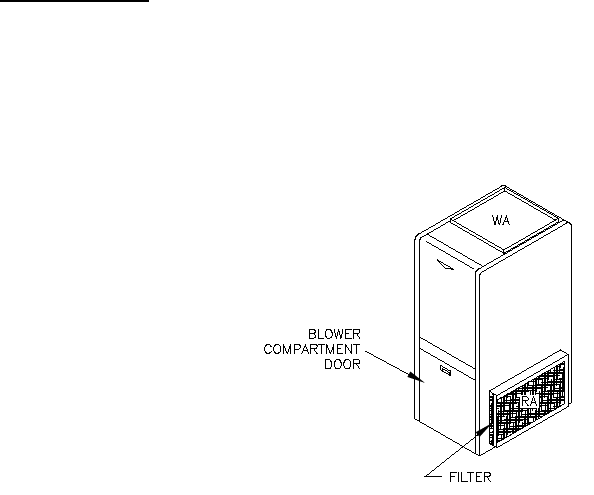
49
D. STARTING THE BURNER:
1. Turn the main service switch to "OFF" position.
2. Set thermostat substantially above room temperature.
3. Open shut-off valves in oil supply line to burner.
4. Turn service switch to furnace "ON". If burner starts and runs, but stops again on lockout, it may be
necessary to bleed the lines or make burner combustion air adjustments. Contact a qualified service
person to adjust and start burner.
E. FILTER CLEANING AND LOCATION:
WARNING: To avoid injury from moving parts, hot surfaces, or electrical
shock, shut off the power to the furnace before removing any furnace access
doors to service the air filters.
The air filters should be inspected each month and cleaned when dirty. Cleaning the air filters frequently
may reduce airborne contaminants from entering the furnace and depositing in the furnace, duct system
and home.
Fig 23: Filter Location for Typical Highboy Furnace

50
IV. INSTALLER'S INSTRUCTIONS TO USER:
After completing the installation, the installer shall inform and/or demonstrate to
the homeowner the following items:
1. The location of these instructions. The instructions must be kept along with instructions for any
accessories in the plastic pouch with the appliance.
2. The location and use of the manual oil shutoff valve and appliance electrical disconnecting
device. The end user must be instructed to always shut off the electric power to the appliance,
before shutting off the oil supply.
3. The sequence of operation of the appliance.
4. The correct operation and maintenance of the appliance, as outlined in the Homeowner/User
Information and Routine Maintenance section of this manual.
5. That failure to maintain and operate this appliance in accordance with these instructions could
result in hazardous conditions, property damage, and bodily injury. It may also void the limited
warranty on the appliance.
6. Review with and encourage the user to read the label reproductions and all warnings and
instructions outlined on the front cover and in Sections I, II, and III, of this manual.
7. Recommend the user have a qualified heating contractor inspect the entire appliance at least once
a year. Inform the user of the frequency of inspection required for each item in the Dealer
Maintenance section of this manual.
8. Inform the user to maintain adequate clearances around air openings into the appliance housing
and not to block or restrict the entrance of air into the condenser coil or the burner compartment air
openings.
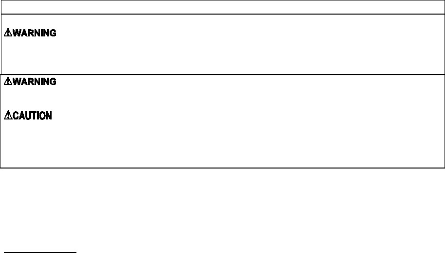
51
V. DEALER MAINTENANCE:
SAFETY DURING SERVICING AND INSPECTION
: Personal injury or property damage could result from repair or service of this
appliance by anyone other than a qualified heating contractor. The user may only perform the
activities described in the Homeowner/User Routine Maintenance section of this manual.
: To avoid injury from moving parts, or electrical shock, shut off the power to the
appliance before removing blower compartment door and servicing this appliance.
: When servicing controls, label all wires prior to disconnecting. Reconnect any
removed wires correctly. Wiring errors can cause improper and dangerous operation.
Dangerous operation can result in injury or damage.
IMPORTANT: Verify the proper operation of this appliance after any servicing is performed.
A qualified heating contractor should perform the following maintenance procedures at the
beginning of each heating season. Correct any deficiencies at once.
A. GENERAL INSPECTION:
WARNING: Shut off oil and disconnect power before continuing with this
inspection.
1. Vent terminal - Visually inspect the terminal for restrictions, loose or missing fasteners, external
damage, and carbon build-up. Clean the vent terminal and the screen(s) covering any opening in
the terminal. Repair any minor damage. If necessary, replace a severely damaged or degraded
vent terminal.
2. Burner – Visually check the burner, and below the burner, for indications of oil leaks. Correct any,
if found. Remove the burner and measure the ignition electrode gap. It should be set to 5/32 inch.
Adjust it, if necessary. Clean any accumulation of dust, dirt, or debris from the air shutter or air
band openings. If necessary, clean housing and blower wheel with a damp cloth. Use a vacuum
to remove any lint or dust from motor assembly. Add a few drops of non-detergent oil to each of
the motor lubrication holes.
3. Combustion Chamber - Inspect the liner for deterioration, oil and carbon build-up. If the
accumulation of oil or carbon is significant, this is a strong indicator that the burner is out of
adjustment. Inspect the burner nozzle for partial blockage and excessive wear. Replace it, if
required. Check and adjust oil pump pressure, if needed. Refer to Initial Heating System
Adjustments section of this manual.
Note: Care must be given to ensure no damage occurs to the chamber insert. (Refer to Figure 12)
4. Heat Exchanger – Visually inspect the heat exchanger for excessive carbon (soot) build-up. Refer
to the Heat Exchanger section of the manual.
5. Oil Filter – Replace the supply line oil filter cartridge with a new filter of the same type and rating.
Clean the body of, or mounting plate for, the oil filter.
6. Labels and Markings - Clean all appliance labels, markings, and instruction plates, as necessary,
and verify that all are still legible. Any illegible or missing markings must be replaced.
Replacements can be obtained by contacting Thermo Products.

52
B. HEAT EXCHANGER:
WARNING: A qualified heating contractor must clean the heat exchanger.
At least once a year, inspect the heat exchanger for evidence of corrosion, pitting, warpage, deterioration,
and carbon (soot) build-up. A layer of soot on the inside of the heat exchanger will act as an insulator and
reduce heat transfer, resulting in less heating efficiency.
Also, look for loose or deteriorated gaskets and insulation around the flue pipe, the burner, and
accessible areas of the heat exchanger. If this inspection indicates heat exchanger cleaning is necessary,
follow the heat exchanger cleaning instructions below.
C. HEAT EXCHANGER CLEANING INSTRUCTIONS:
WARNING: THE HEAT EXCHANGER MUST BE CLEANED BY A QUALIFIED
SERVICE PERSON.
It is important to inspect and clean the heat exchanger once a year, or as necessary, to remove any build-
up of soot. A layer of soot on the inside of the heat exchanger will act as an insulator and reduce heat
transfer, resulting in less efficiency.
1. To clean the heat exchanger, first turn off all power to the unit. Remove clean-out plugs, the vent
connector pipe to the chimney, the burner, and the burner mounting plates. When removing the clean-out
plugs, turn T-handle counterclockwise approximately two (2) full turns or just until the plug is able to be
pulled from tube. Take care not to remove T-handle from assembly.
2. With access to the inside of the heat exchanger through the burner area, clean-out openings, and vent
pipe connection, it is possible to use a long, flexible wire brush and an industrial type vacuum cleaner to
remove any soot build-up. NOTE: A one inch (outside diameter) vacuum cleaner hose will fit into the
radiator.
To vacuum and brush the outer radiator of the heat exchanger, go through the clean-out openings in both
directions, as shown in figure 25 on the next page.
3. Reassemble the furnace to its original construction*. Remount the burner being certain that the air
tube is properly inserted into the chamber opening. If heavy soot deposits were found in the heat
exchanger, this may indicate the burner is out of adjustment.
*When returning clean-out plugs to their original position, insert plug and turn T-handle clockwise 2-3
turns or until plug cannot be pulled from the clean-out access tube. This is sufficient for sealing the
access tube.
Replace any damaged or corroded components. All gaskets and insulation must
be inspected, and replaced, if they show any signs of damage.
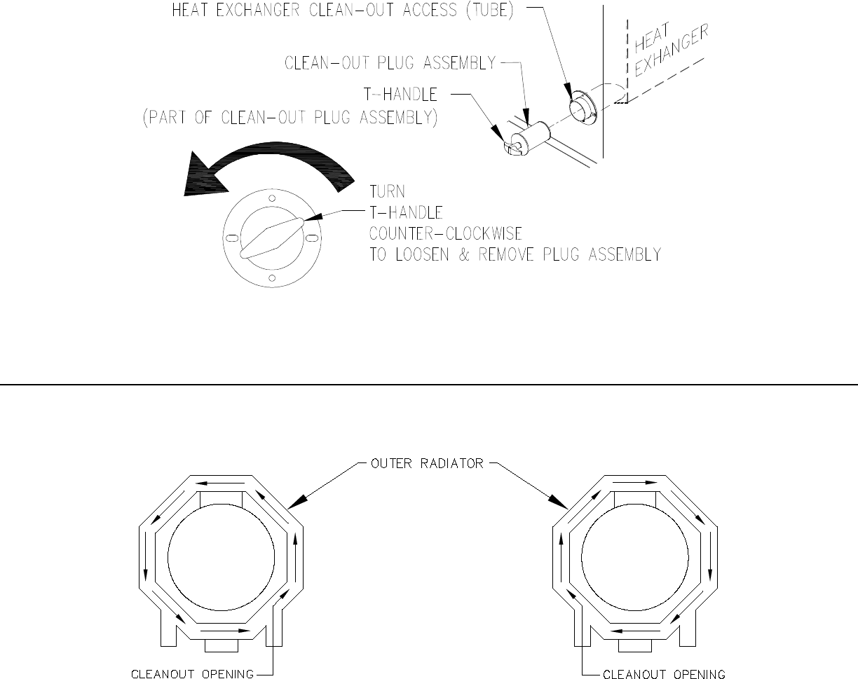
53
Figure 24: Heat Exchanger Clean-Outs
Vacuum Hose Length
OH6 8FT
OH8 8FT
Fig. 25: Recommended method and device for cleaning inside of heat exchanger.

54
4. Operational Check:
CAUTION: Before troubleshooting, familiarize yourself with the start up and
check out procedures
NOTICE: After reassembling the appliance, check for fuel oil leakage from the
supply piping.
a. Check proper operation of the ignition system and for proper combustion.
b. Observe the main burner flame. If the flame appears strange or abnormal in character, look for a
component or components that were not reassembled correctly. If the components have been
reassembled correctly, check for a blocked vent, malfunctioning combustion air blower or fuel pump,
and partially blocked burner nozzle.
D. ELECTRICAL SYSTEM:
WARNING: When servicing controls, label all wires prior to disconnecting.
Correctly reconnect any wires removed during servicing. Wiring errors can cause
improper and dangerous operation. Dangerous operation can result in injury or
damage.
1. Check all wiring for loose connections and any signs of damage, or unusual wear. Replace any
damaged or frayed wiring and tighten any loose connections.
2. Use a voltmeter, or a multimeter, to check for adequate voltage at the field connections when the
appliance operating.
3. Use an ammeter, or a multimeter, to check the current draws of the blower motor and burner assembly,
to assure they are not exceeding rating label current specifications for each component. Also, refer to
Table 10 in the electrical wiring section of this manual for electrical specifications on these components.
4. Check for correct operation and proper settings (if manually adjustable) of all controls.
E. SUPPLY/RETURN AIR BLOWER:
Check in the blower compartment for dust, dirt, debris, and for the presence of insects. Remove any
foreign material. Clean the blower wheel, housing, and compartment of dust and lint with a vacuum.
The blower motor has sealed bearings that are permanently lubricated. The blower motor bearings do
not require oil or any type of additional lubrication.
F. SUPPLY/RETURN AIR FILTER:
The filter rack will be located between the return air plenum and the return air opening on the side of the
furnace. This filter should be inspected regularly. When the filter is dirty, it should be cleaned or replaced
to assure proper heating/cooling system operation. Follow the cleaning, removal and replacement
procedure below.
Filter maintenance procedure:
Shut off the electrical power to the unit. Open the access door. Slide the air filter out of the filter rack.
Clean the filter by either vacuuming, rinsing with tap water, hosing, or dipping in an ordinary detergent
solution. After cleaning and drying the filter, replace the completely dry filter in the rack. If the filter has a
supporting mesh, the mesh side of the filter must be placed towards the furnace.
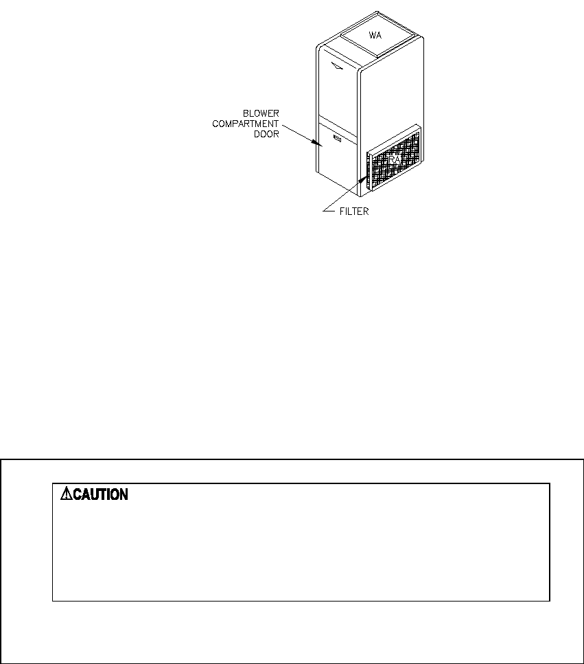
55
Figure 26: Location of Supply/Return Air Filter
Filter replacement:
To ensure an adequate replacement filter is selected, should the filter require replacing, refer to Table 4,
in Air Filters section of this manual, for the minimum filter areas required for different types of available
filters.
NOTICE: Remind the homeowner of the importance of monthly filter inspections
during operation to ensure maximum operating efficiency.
G. EXTENDED APPLIANCE SHUTDOWN:
Should the appliance be shutdown or turned off for an extended period of time, several steps can be
taken to help insure a smooth and reliable restart of the heating system.
ON SHUTDOWN:
1. Close oil supply (or manual shutoff) valve.
2. Disconnect all electrical power to the unit.
3. Fill the oil tank to reduce water condensation in the tank.
4. If the shutdown period will exceed one heating season, an oil stabilizer should be added to the oil
tank. Consult your oil supplier for recommendations.
: Do not attempt to start burner when:
•
Primary reset has been engaged more than two times.
•
Excess oil has accumulated in the combustion chamber or beneath
the burner assembly.
•
The combustion chamber or the heat exchanger is full of fuel vapor.
•
The combustion chamber is very hot.
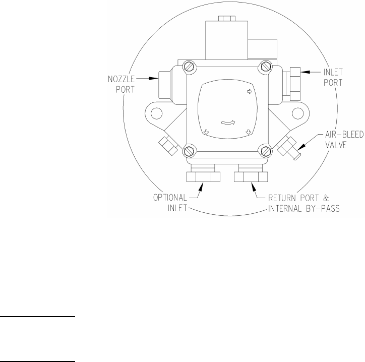
56
ON STARTUP:
1. Have system inspected and started by a qualified heating contractor.
2. Check oil level in tank. If the tank has not been filled with fresh oil, inspect the remaining oil for
signs of contamination with water, algae, dirt or other impurities. If excessive, consult your oil
supplier for recommendations.
3. Change the oil filter cartridge and clean the canister.
4. Set the room thermostat above room temperature.
5. Open all valves in the oil supply line.
6. Open the inspection cover on the upper mounting plate.
7. Turn on the electrical power to start the burner. If the burner does not start, immediately reset the
manual overload switch on the motor (if so equipped) and the safety switch of the burner
primary control. Bleed air from the fuel oil line as soon as the burner motor starts rotating. To
bleed the fuel pump, attach a clear plastic hose over the vent plug, refer to Figure 27. Loosen
the plug and catch the expelled oil in an empty container. Tighten the plug when all the trapped
air appears to be purged. If the burner stops during bleeding, wait three to five minutes for the
control safety switch to cool. Then manually reset the switch. Continue bleeding the line until the
air is completely removed.
Figure 27: Location of Oil Pump Vent Plug
8. Follow the previous Initial Burner Operation procedures.
VI. HOMEOWNER/USER INFORMATION AND ROUTINE MAINTENANCE:
WARNING: Never burn garbage or refuse in this appliance. Never try to ignite
oil by tossing burning papers or other material into the combustion chamber.
WARNING: Oil-fired appliances produced by Thermo Products are designed for
burning No. 2 distillate (domestic heating) fuel oil. Never use gasoline or a
mixture of oil and gasoline.
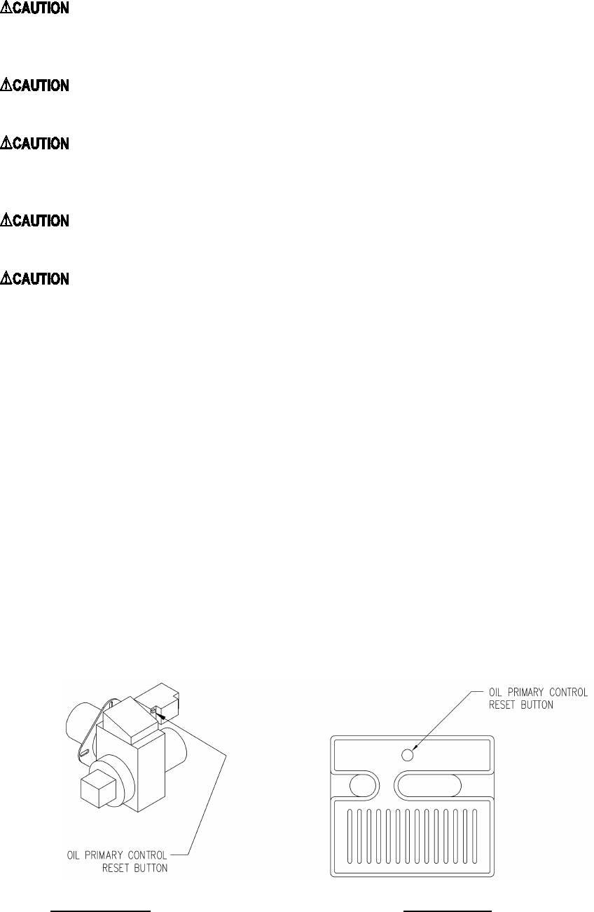
57
: Do not use this appliance if any part has been under water. Immediately
call a qualified service technician to inspect the furnace and to replace any part of
the control system and any oil control that has been under water.
: Should overheating occur, or the oil supply fail to shut off, shut off the
electrical power to the appliance, before shutting off the manual oil valve.
: The area around the appliance, including the top of the unit, must be
kept clear and free of combustible materials, gasoline, and other flammable
vapors and liquids.
: The appliance vent terminal may be hot. If the terminal is hot, allow it to
cool before touching it.
: Do not attempt to make repairs yourself. Contact your local qualified
heating contractor.
Under normal conditions, this appliance will operate in either heating or cooling mode, depending upon
the mode of operation set at the thermostat. The unit will cycle on and off automatically, as required, to
maintain the air temperature within the residence as closely as possible to the thermostat setting.
However, in rare cases, the unit may shutdown automatically during a normal cycle or may not operate
under seemingly normal conditions.
If the unit will not operate in the heating mode, it may be possible to reactivate the unit by resetting
one of the burner controls. To attempt resetting of the burner controls, follow this procedure.
1. Turn the thermostat temperature setting down and set the operating mode to “OFF” or
“COOLING”.
2. Remove the furnace front door.
3. Check to see if the LED on the burner primary (ignition) control module is flashing at a rapid rate.
If so, the control may have “locked out”. To recycle the control system, depress the reset button.
Refer to Figure 28.
4. Replace and secure the furnace front door.
5. Set the operating mode on the thermostat to “HEATING” and turn the thermostat temperature
setting up.
Beckett Burner Riello Burner
Figure 28: Location of oil primary control reset button

58
If this action does not reactivate the unit, contact a qualified service agency for assistance.
In general, if the thermostat is set in the heating mode, the heating system functions entirely
automatically. However, under certain circumstances, the appliance may not be able to fire the burner.
For instance, if the manual oil shutoff valve has been closed or the oil tank is out of fuel, the oil line may
have air trapped in it. It will be necessary to purge the air by bleeding the supply line from the tank to the
burner again for the heating system to operate. Refer to the instructions under the Extended Appliance
Shutdown section of this manual.
NOTICE: Thermo Products recommends that the user/homeowner, contact a qualified service
agency for assistance in bleeding the fuel line(s) and lighting off the heating section.
The following maintenance points should be reviewed periodically to assure the heating and cooling
systems continue to function properly.
: Shut off unit and disconnect the power source before disassembling the unit.
: Never operate the appliance without clean air filters in place.
: This appliance requires air for combustion, ventilation, and cooling. Do not block or
obstruct air openings in the unit and the air space around the perimeter of the unit.
1. At least every three months, under normal usage conditions, check and clean all air filters in the
appliance and, if present, in the duct system. If excessively dirty air filters are not cleaned, or
changed, poor system performance will result due to reduced airflow. Low airflow places
unnecessary strain on the compressor, possibly causing the system to shutdown on the
refrigerant high-pressure switch. Refer to Figure 23 for a sketch of the filter location.
2. Do not allow the fuel oil tank to run completely empty. During the summer, keep the tank full to
reduce condensation of moisture on the inside surface of the tank. If the fuel tank runs
completely dry, it may be necessary to bleed air from the fuel lines. Contact a qualified heating
contractor to bleed the lines and restart the burner.
3. Check the supply and return air connections to the appliance to insure the seals between the
duct and appliance and the appliance and home are intact. Check the ducts for any signs of
collapse, holes, or excessive corrosion. Repair or replace components as required.
VII. TROUBLESHOOTING:
THIS SECTION IS ONLY TO BE PERFORMED BY TRAINED, QUALIFIED SERVICE
PERSONNEL, AND NOT BY THE FURNACE OWNER.
NOTICE: Before troubleshooting, familiarize yourself with the Initial Startup,
Checkout Procedure, and Troubleshooting Flowchart.
Refer to the appendices of this manual for an electrical schematic, a connection diagram, flowcharts to
assist in troubleshooting, product specifications, and a replacement parts list follow for this appliance.
1. Check for 115VAC line supply voltage to the furnace. If there is no supply voltage, check fuses and
service switch.
CAUTION: When testing electrical equipment, always follow standard electrical procedures.
59
2. Make sure thermostat is calling for burner operation.
3. Check oil supply and make sure all valves are open.
A. DIAGNOSTICS:
To assist in troubleshooting this appliance, it is equipped with an integrated safety and ignition control
with diagnostics. These diagnostics include an indicator light that relays the operational status of the
control and can help in diagnosing the condition of the flame sensor.
Diagnostic Features:
The Beckett Genisys safety and ignition control module used on this unit continuously monitors the
operation of the heating system. If an abnormal condition occurs, the LED light on the control will rapidly
flash indicating the operational status of the unit. In event this control malfunctions, the entire control
should be replaced. It is not field-repairable.
In the event of an operational failure of the burner system, the rate of flashes, if any, of the ignition control
module LED should be noted, before turning off power to the unit. Otherwise, power to the heating
section will be interrupted and the control LED will not furnish the diagnostic flashing. It may be necessary
to restart the furnace and have the failure occur again. For the model R7184B, under normal operating
conditions, the LED will be continuously lit while the burner is operating.
If either control has sensed a flame failure, which was uncorrected by initiating another trial-for-ignition,
the control will cease ignition trials and shutdown the burner, or “lockout”. The LED will continuously flash
at a high rate (approximately 1/2-second “on”; 1/2 second “off”, for the model R7184B.
: If the appliance fails to relight after resetting the primary control twice contact a qualified
service company. DO NOT continue to reset primary control.
The operational condition of the flame sensor, or “cad cell”, can be checked by depressing the reset
button on the control module, while the burner is operating. Count the number of flashes of the LED and
compare them to the table below.
Number of flashes Cad Cell Resistance (in ohms)
Model R7184B
1
0 to 400
2
400 to 800
3
800 to 1600
4
1600 ≤
If it is necessary to troubleshoot the flame sensor independently of the burner primary, the following
procedure may be used.
B. CAD CELL CHECKOUT PROCEDURE:
1. Stop burner and shutoff electrical power to the appliance.
2. Open burner junction box (on top of the burner blower) and remove the plug-in portion of the cad cell
by pulling it forward from and clear of the receptacle. Connect an ohmmeter across cad cell pins. With the
cell exposed to direct room light, the measured resistance should be less than 2500 ohms (in fact, it may
be less than 200 ohms).
60
3. Check the resistance across the cad cell pins with the cell covered (protected from exposure to
ambient light). The resistance should be greater than 20,000 ohms.
4. If cell resistances are different from above, replace the plug-in portion of cell, (Honeywell Part No.
130367).
5. Carefully reinsert the plug-in portion of the cad cell into the receptacle. If the cad cell appears to be
functioning correctly, troubleshoot the fan control module and the safety and ignition control (primary
control) module, according to the Honeywell instructions covering the devices.
The troubleshooting chart beginning on the following page should help identify the type of malfunction or
deviation from normal operation. To use this diagram, just follow the instructions in the boxes. If the
answer is yes or the condition is true, go down to the next box. If the answer is no or the condition is
false, go to the box on the right. Continue checking and answering questions and conditions in each box
until a problem and/or repair is found. After any maintenance or repair, the trouble shooting sequence
should be repeated until normal system operation is achieved.

61
VIII. Sequence of Operations Flow Chart:
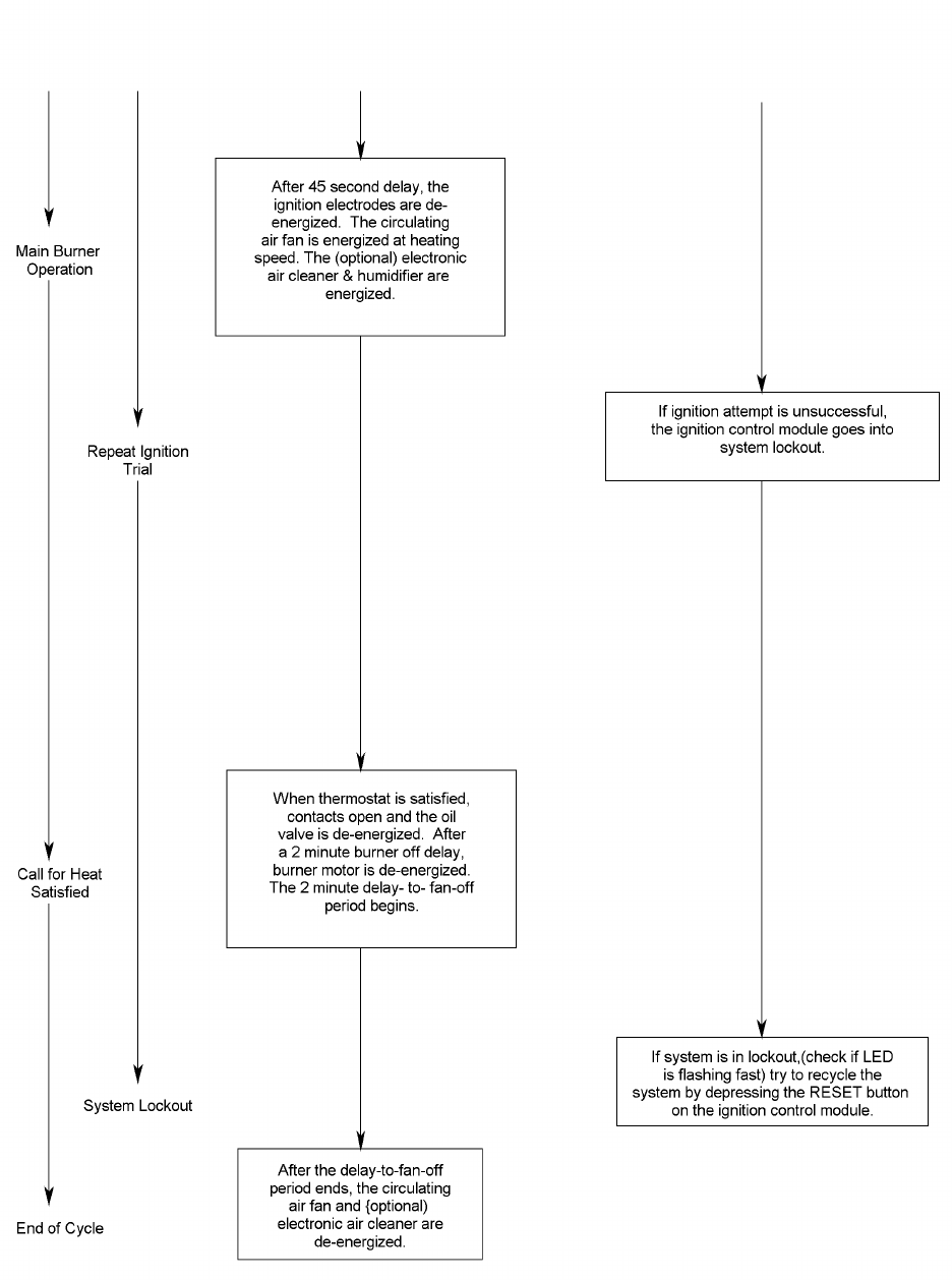
62
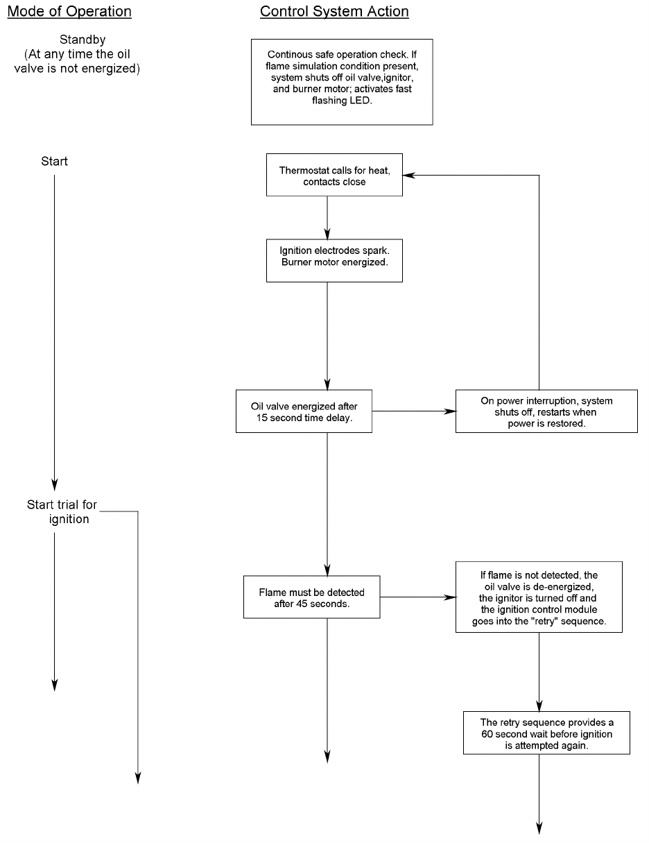
63
IX. Trouble Shooting Flow Chart:
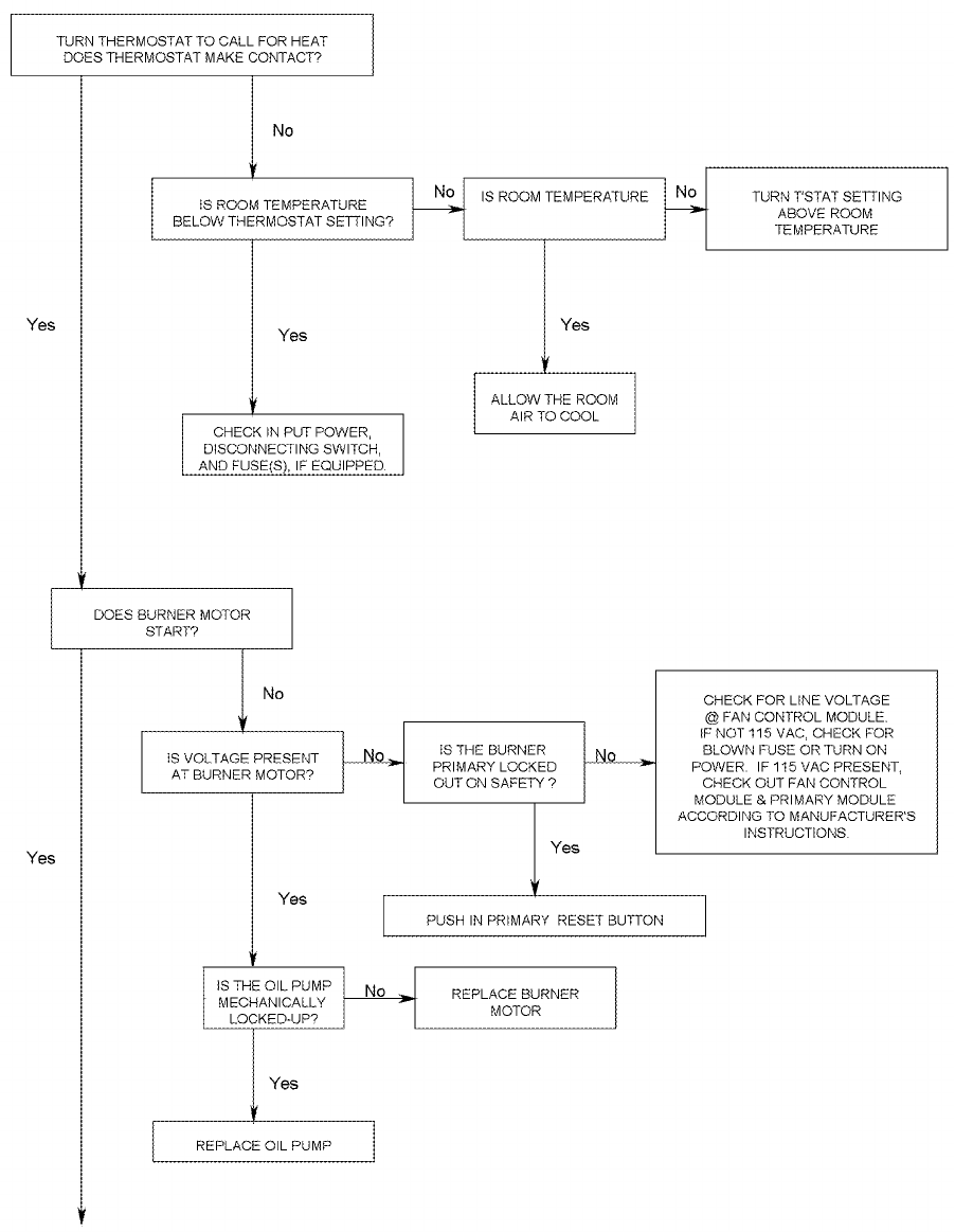
64
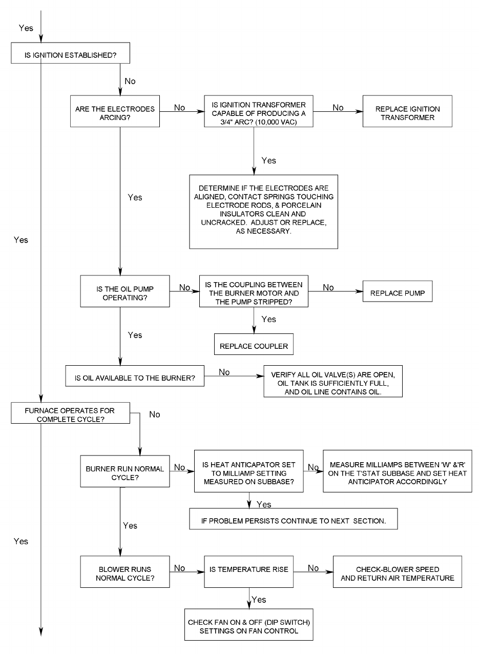
65
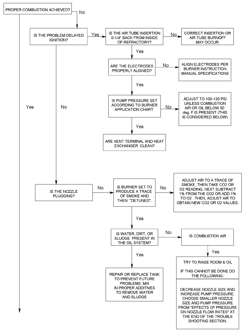
66
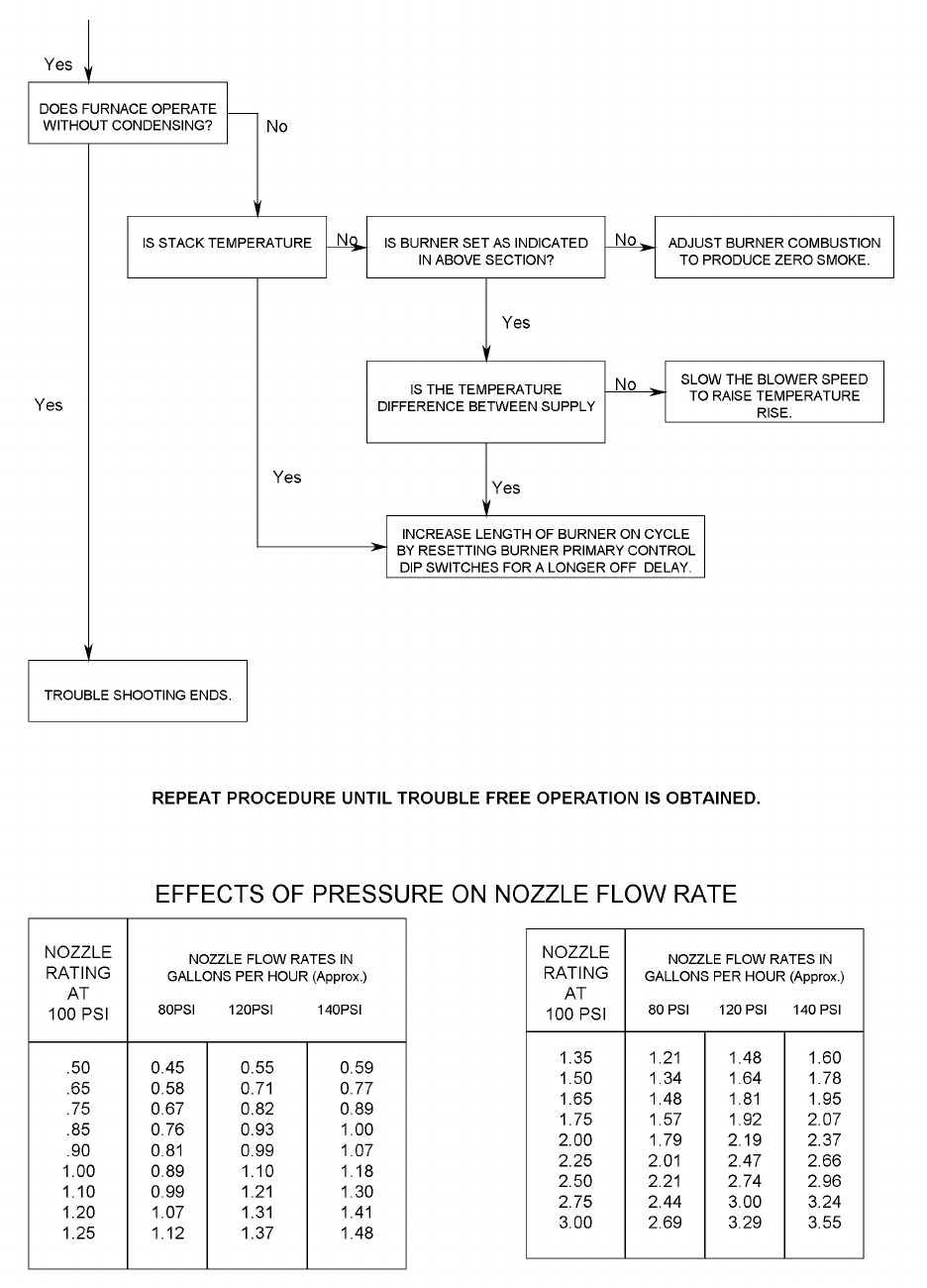
67
68
COMBUSTION AND EFFICIENCY TESTING FOR THERMO PRIDE
OIL FIRED CENTRAL FURNACES.
Complete this form for each Thermo Pride furnace installed. Read instruction
CUSTOMER NAME
ADDRESS
CITY, STATE
HEATING
SY ST EM
BURNER MODEL NO. AIR SHUTTER OPENING
INS. % OF M A X . ( EST)
FURNACE MODEL
TYPE OF VENTING SYSTEM
M A SON RY
CHIMNEY
METAL
CHIMNEY
SI DEWA L L
POWER VENTER
M A SON RY
CHIMNEY
W/INDUCER
METAL
CHIMNEY
W/INDUCER
MASONRY CHIMNEY
W/METAL LINER
FUEL LINE FILTER DRAFT CONTROL
COMBUSTION
TESTS
(Oper ate bur ner
at least 10
minutes befor e
CO2 in stack pipe
INITIAL SERVICE SERVICE SERVICE
INSTALLATION
Draft Over-fire
Draf t i n stack pi pe
Smoke number
Furnace room temp.
Gross stack temp.
Net stack temp.
(Gross stack mi nus
f urnace room temp.)
Efficiency
Nozzl e si ze and spray
Date
NOTES:
INSTALLER NAME & ADDRESS
manual carefully before making tests. Retain this form with furnace.
BLAST TUBE LGTH.
Tests taken by
st ar ting t est s.)
COMBUSTION CHAMBER CONDITION MATERIAL
FURNACE SERIAL NUMBER
Oil pump pressure
Operation of Controls
Burner Saf ety Control s
Check f or oi l leaks
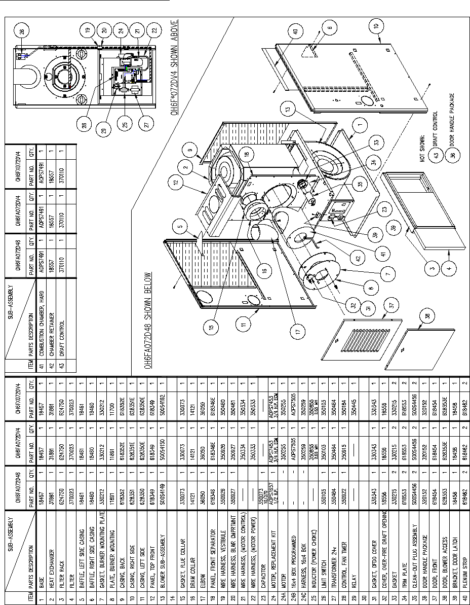
69
Appendix – A
Replacement Parts:
Replacement Parts for OH6FA072D**
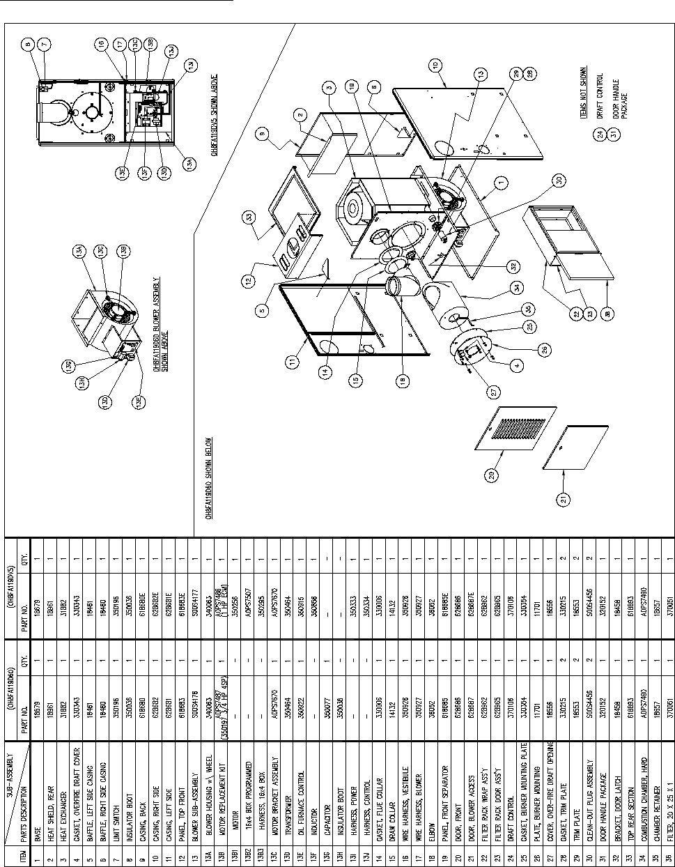
70
Replacement Parts for OH8FA119D**
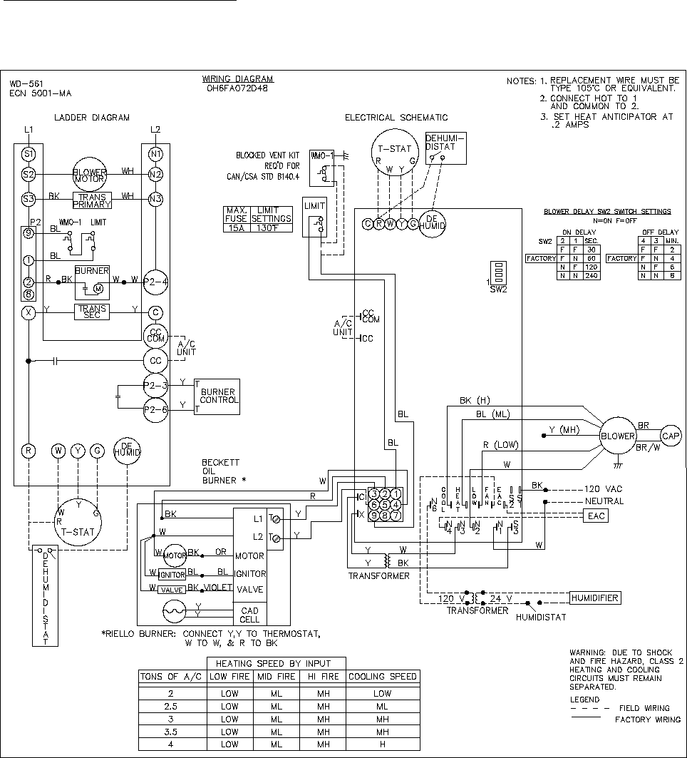
71
Appendix – B
Wiring Diagrams
OH6FA072D48 PSC Wiring Diagram
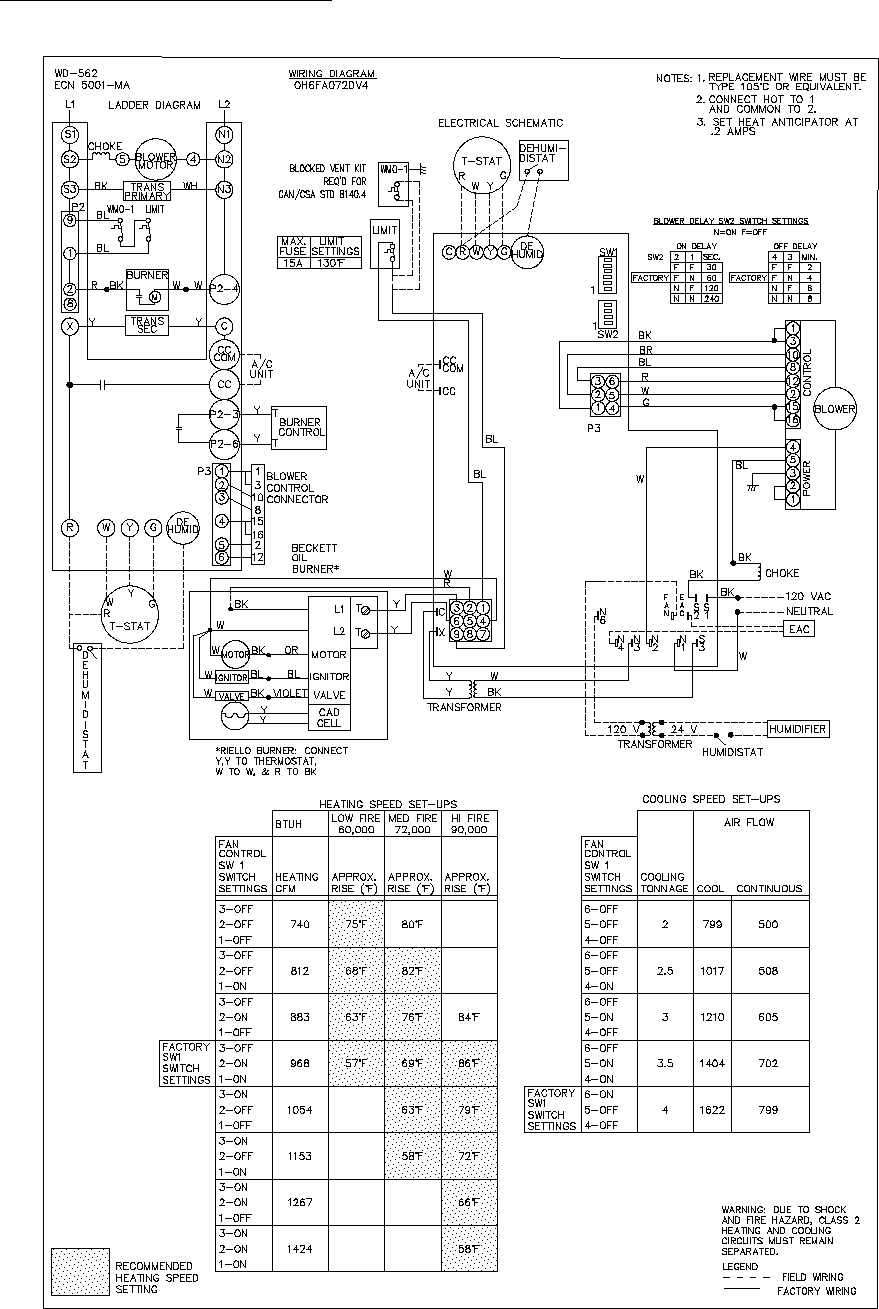
72
OH6FA072DV4 ECM Wiring Diagram
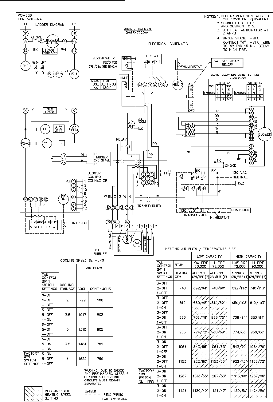
73
OH6FX072DV4 ECM 2-Stage Wiring Diagram
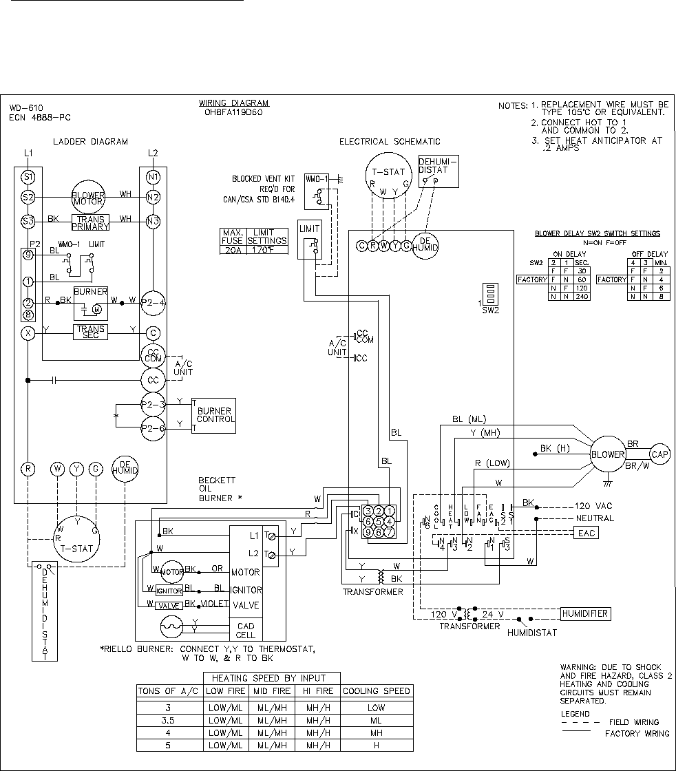
74
OH8FA1119D60 PSC Wiring Diagram
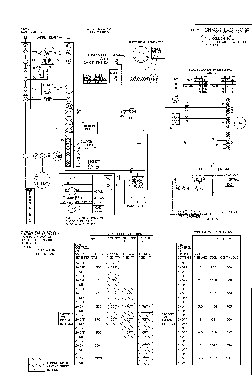
75
OH8FA1119DV5 ECM Wiring Diagram
