Thermo Products Pride Impact Driver Ah1 A Users Manual Figure A.
AH1-A to the manual 2ab0d87e-29ba-46ca-ab2a-0a99710f81db
2015-02-03
: Thermo-Products Thermo-Products-Thermo-Pride-Impact-Driver-Ah1-A-Users-Manual-461771 thermo-products-thermo-pride-impact-driver-ah1-a-users-manual-461771 thermo-products pdf
Open the PDF directly: View PDF ![]() .
.
Page Count: 22
MAC-165
ECN 4392-MA
10 & 12 SEER
AIR HANDLER
INSTALLATION & SERVICE MANUAL
MODELS: AH1-A, AH2-A
PLEASE READ THESE INSTRUCTIONS PRIOR TO INSTALLATION AND BEFORE
PERFORMING ANY SERVICE OR MAINTENANCE. THESE INSTRUCTIONS MUST
BE LEFT WITH THE USER AND SHOULD BE RETAINED FOR FUTURE
REFERENCE BY QUALIFIED SERVICE PERSONNEL.
: Improper installation, adjustment, alteration, service, or maintenance can
cause injury or property damage. Refer to this manual. For assistance or additional
information consult a qualified installer, service agency, or manufacturer listed below.
THERMO PRODUCTS, LLC.
BOX 217
NORTH JUDSON, IN 46366
PHONE: (574) 896-2133 MADE IN USA

TABLE OF CONTENTS
SECTION BEGINNING PAGE
SAFETY SECTION 1
KNOCKDOWN OF AIR HANDLER 3
REASSEMBLY OF AIR HANDLER 3
INSTALLATION OF A-COIL IN A VERTICAL APPLICATION 3
INSTALLATION OF A-COIL IN A HORIZONTAL APPLICATION 4
INSTALLATION OF HOT WATER COIL 6
BLOWER AIR ADJUSTMENT 7
DUCT SYSTEM 9
CFM CAPACITY CHARTS 10
DUCT SIZING CHART 11
INDOOR EVAPORATOR COIL 11
TUBING LINE SETS 12
SUPERHEAT MEASUREMENT 15
MEASURING TEMPERATURE DROP 16
ELECTRICAL 17
UA ADAPTER CABINET 17
RECOMMENDED SUSPENSION PROCEDURE FOR AH AIR HANDLER 18
REPLACEMENT PARTS LIST 19
OUTLET AIR TEMPERATURE VS HEATING CAPACITY CHARTS 20

All installations and services must be performed by qualified personnel.
1
SAFETY SECTION
This page contains various warnings and cautions found throughout this Service and Installation
Manual. Please read and comply with the statements on the cover and the statements below.
: Improper installation, adjustment, alteration, service, or maintenance can
cause injury or property damage. Refer to this manual. For assistance or additional
information consult a qualified installer, service agency, or manufacturer listed below.
: If drilling or screwing into panel or plate is necessary, make certain drill or screw
does not penetrate into any part of evaporator coil or hot water coil and cause damage. Personal
injury and/or property damage may result.
: Do not use this system if any part has been under water. Immediately call a
qualified service agency to inspect the system and to replace any part of the electrical or control
system which has been under water.
: The cooling and heating coils must be cleaned by a qualified service person.
: This air handler is not to be used to condition during construction.
: When testing electrical equipment, always follow standard electrical procedures
and precautions.
: DO NOT wet electronic components during hydronic testing. Wetting
electronic components may damage circuitry and cause a hazardous situation. Dry moisture from
all leads and terminals if wetting occurs. Wait at least 24 hours for the circuit to fully dry before
energizing the system.
: Personal injury or property damage could result from major repair or service of
this system by anyone other than a qualified contractor.
: If you do not follow these instructions exactly an unsafe condition may result
causing personal injury, loss of life or property damage.
All installations and services must be performed by qualified personnel.
2
Installation and service personnel are required by some states to be licensed. Persons not
qualified shall not install this equipment nor interpret these instructions.
All local codes and regulations take precedence over the instructions in this manual and should
be followed accordingly. In the absence of local codes, installation must conform with these
instructions, regulations of the National Fire Protection Association and provisions of the
National Electric Code.
AIR HANDLER
Each air handler is capable of operation within a range of evaporator coil sizes. The evaporator
size specified is shipped as a separate item and must be installed by the contractor. Model AH2-
A will accommodate the 1060-G1, 1242-G1, 1042E, and 1048E. The AH1-A will accommodate
the 1024E, 1030E, 1036E, 1224-G1, 1230-G1 and 1236-G1.
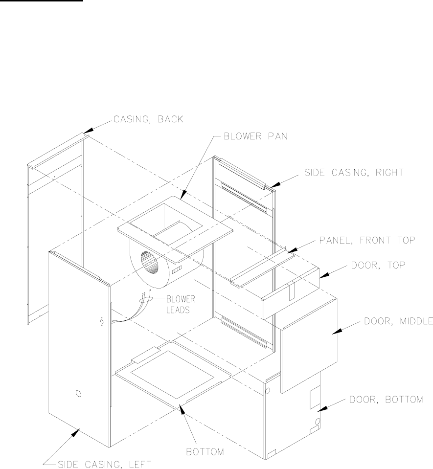
The construction of the air handler permits easy knockdown and reassembly. See Figure A.
Figure A
All installations and services must be performed by qualified personnel.
3
FOLLOW THESE STEPS FOR KNOCKDOWN OF AIR HANDLER:
1. Start with unit setting in a vertical position. (Figure A)
2. Remove screws from bottom door, middle door, top door, and top front panel. Remove doors
and top panel of air handler.
3. Disconnect blower leads from blower terminal strip.
4. Remove screws that secure the blower pan to the side casings and the back casing.
5. Pull blower sub-assembly up and out the front of the unit.
6. Remove screws from the bottom and the casing back.
7. Remove casing back and side casings from the bottom.
REASSEMBLY OF AIR HANDLER
To reassemble the air handler, reverse steps above starting with number 7.
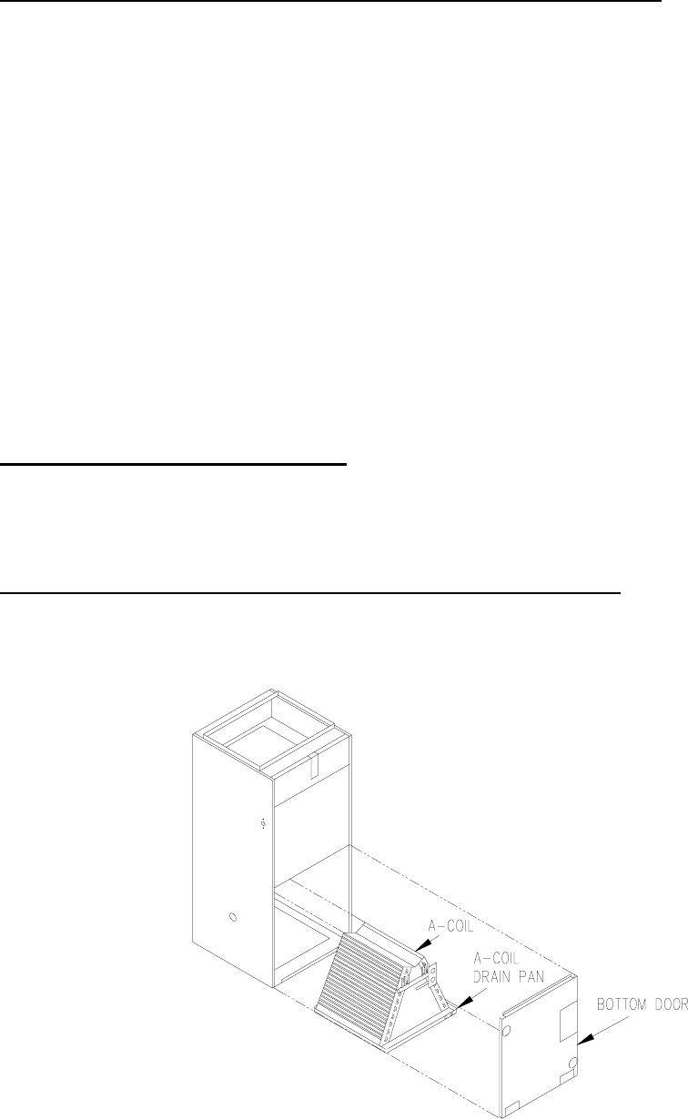
INSTALLATIONS OF A-COIL IN VERTICAL APPLICATIONS
A standard Thermo Pride A-coil is used in all air handlers. The coil and its attached drain pan are
installed in the air handler. See Figure B1.
Figure B1
All installations and services must be performed by qualified personnel.
4
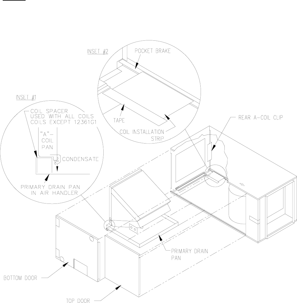
INSTALLATIONS OF A-COIL IN HORIZONTAL APPLICATION
For the AH1-A, in all A-coil applications (1024E, 1030E, 1036E, and 1224-30G1) except the
1236G1, the A-coil spacer must be used.
For the AH2-A, in all A-coil applications the A-coil spacer must be used.
1. Remove bottom door of air handler.
2. Remove middle door of air handler.
3. Slide primary drain pan out of unit.
4. Set A-coil spacer in primary drain pan if needed. See Figure B2, #1 inset.
5. Set A-coil in place on primary drain pan.
6. Secure coil installation strip with aluminum tape as indicated in Figure B2, inset #2.
This makes a small ramp to slide the coil up and on the rear pocket brake.
7. Slide pan with coil into air handler making sure that the A-coil plastic pan is properly
positioned in the primary drain pan. Insure the plastic coil pan on base of the A-coil slides
into rear clip. See Figure B2.
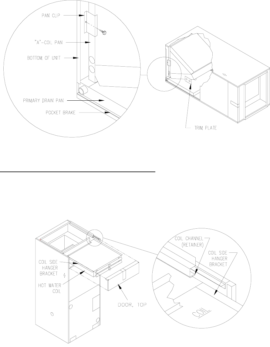
8. Secure front of plastic pan to bottom of unit with supplied pan clip. See Figure B3 inset.
An extension for nut driver may be of benefit.
9. Pan should rest on pocket brakes on each side of side casing when properly installed.
IMPORTANT: When air handler is installed in attic above a finished ceiling, it is
recommended that a safety overflow pan with its own separate drain be installed under
the entire unit.
10. Remove trim plate from A-coil connections.
11. Cut out appropriate holes in insulation, remove appropriate knockouts, and realign coil
access panel and secure into place
12. Make appropriate liquid and suction line connections to coil and braze connections.
NOTE: A wet rag makes an excellent heat sink for tubing.
: If drilling or screwing into panel of plate is necessary, make certain drill does not
penetrate into any part of evaporator coil or hot water coil to avoid personal injury and/or
property damage.
All installations and services must be performed by qualified personnel.
5
13. Position grommets in coil access panel to allow installation of trim plate, secure trim
plate in place with screws, and seal connections with duct sealer or equivalent.
NOTE: The air handler is factory assembled for left to right(horizontal) and vertical
applications. If a right to left horizontal application is desired, the fan center must be moved to
the right side casing which will position it above the primary drain pan.
Figure B2
All installations and services must be performed by qualified personnel.
6
Figure B3
INSTALLATION OF THE HOT WATER COIL:
1. Remove top door of air handler.
2. Slide hot water coil's side hanger brackets into coil channel(retaining channel) in the air
handler. See Figure B4 inset.
Figure B4
3. Push coil into unit until the coil is stopped by the back casing.
4. Cut out appropriate holes in insulation, realign top door and secure into place.
All installations and services must be performed by qualified personnel.
7
5. Make appropriate hydronic connections to inlet(blower side) and outlet(duct side) of coil and
braze into place.
6. Seal connections through panel with duct sealer or equivalent.
: If drilling or screwing into panel or plate is necessary, make certain drill does not
penetrate into any part of evaporator coil or hot water coil. Personal injury and/or property
damage may result.
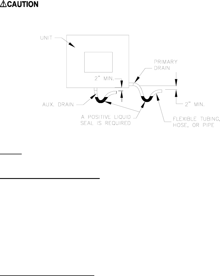
Figure C
NOTE: Drain lines must be pitched no less than 1/4" per foot away from the air handler.
TRIM PANEL INSTRUCTIONS:
Included as a loosely packed part in the condensate drain pan of both air handlers is two trim
panels. These panels are to be used in reducing the free area between both the hydronic coil lines
and the evaporator coil lines. The hydronic coil panel has two holes which the inlet and outlet
lines fit through. This panel is to be secured to the air handler via the prepunched holes and
included screws. The evaporator coil panel is a flat rectangular panel measuring 8-1/2” x 3”,
with a 1/2” brake on one edge. The 1/2” brake is to fit into the pocket brake of the side casing
and the larger part of the panel is to be attached to the bottom door via the prepunched holes and
included screws. This panel will close the gap that is created between the side of the air handler,
and the grommet panel that is installed on the evaporator coil.
BLOWER AIR ADJUSTMENT
The direct drive blower must be set in order to establish proper air movement. Use the following
steps to do this:
*For cooling only remove low speed connection to terminal block unless continuous fan is
desired.
All installations and services must be performed by qualified personnel.
8
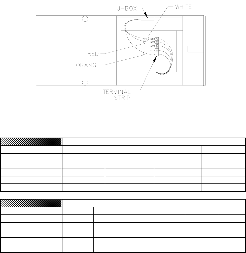
1. Determine the appropriate blower speed settings listed in tables below.
2. Set the blower motor speed to match air conditioning requirement, connect the red
wire(cooling tap) to the appropriate fan speed on the terminal strip located on the blower(see
Figure D).
3. Set the blower motor speed to match heating requirement, connect the orange wire(heating
tap) to the appropriate fan speed on the terminal strip located on the blower(see Figure D).
Figure D
Heating Tap Locations
Terminal Strip Speed 40,000 (btuh) 60,000 (btuh) 80,000 (btuh) 100,000 (btuh)
C White White White White
H
MH
ML
Orange
L Orange Orange Orange
Cooling Tap Locations
Terminal Strip Speed 2 Ton 2.5 Ton 3 Ton 3.5 Ton 4 Ton 5 Ton
C White White White White White White
H Red
MH
Red Red Red
ML Red
L Red
All installations and services must be performed by qualified personnel.
9
DUCT SYSTEM
The duct system and load sizing calculation should follow the design standards of Air
Conditioning Contractors of America (ACCA) - manuals D & J - or the American Society of
Heating, Refrigeration and Air Conditioning Engineers, Inc. (ASHRAE) Latest Edition
Fundamentals Volume.
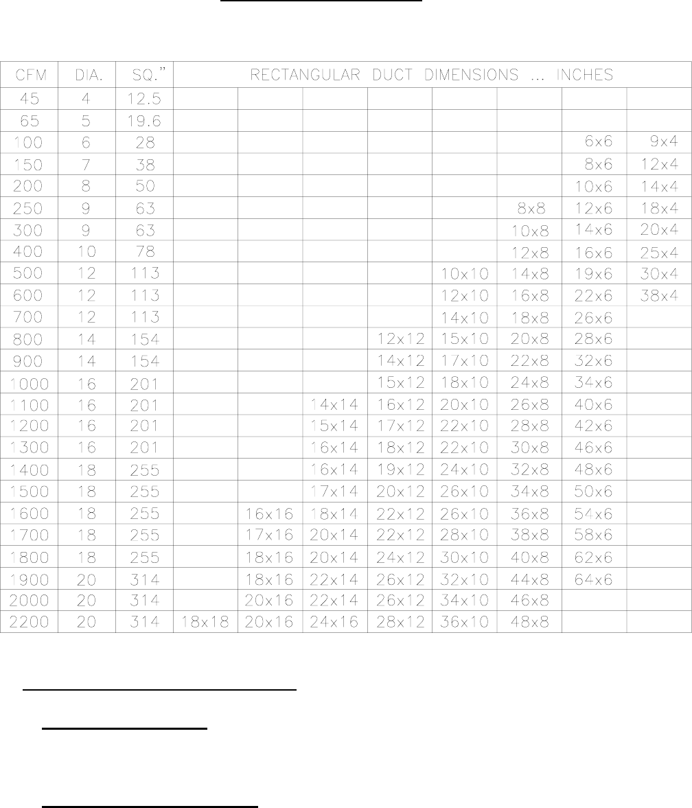
To aid you in evaluating existing duct systems quickly, review the chart on Page 11 which shows
the CFM capacity for square inch areas, based on .10" wc static pressure (SP) loss on the supply
systems.
Each of the system's components (trunk lines, take-offs, runs and register and grill-free areas)
must be properly sized and matched together to ensure you are obtaining the air handling
capacity of the duct system. A 12x8 duct with a 400 CFM capacity, for example, WILL NOT
flow 400 CFM if the register(s) to which it connects can only flow a total of 200 CFM.
The air handling capacity MUST BE EQUAL TO the supply system at a minimum when sizing
the return air duct system. It is recommended to follow design parameters set down by ACCA or
ASHRAE on the return air duct systems.
Heating Capacity
(btuh)
Recommended
Water Flow Rates
for Heating
(GPM)
40,000 4
60,000 6
80,000 8
100,000 10
All installations and services must be performed by qualified personnel.
10
CFM CAPACITY CHARTS
AH1-A
.2 Duct Static Pressure
with heating coil
And applicable Evaporator Coil Model CFM (HI) CFM (M. HI) CFM (M. LOW) CFM (LOW)
1024E and 1030E 1299 1123 992 821
1224-30G1 1756 1202 1073 880
1036E 1435 1231 1055 861
1236G1 1438 1193 1036 860
.2 Duct Static Pressure and applicable
Air Conditioning Coil Only
1024E and 1030E 1390 1243 1085 905
1224-30G1 1591 1335 986 921
1036E 1575 1307 1092 911
1236G1 1523 1280 1074 913
Heating coil
.2 Duct Static Pressure 1514 1261 1055 889
.2 Duct Static Pressure + .3 additional
load 1294 1109 964 785
AH2-A
.2 Duct Static Pressure
with heating coil
And Applicable Evaporator Coil Model CFM (HI) CFM (M. HI) CFM (M. LOW) CFM (LOW)
1060G1 and 1242G1 2052 1632 1326 1034
1042E 1915 1444 1296 1078
1048E 1568 1433 1251 1054
.2 Duct Static Pressure and applicable
Air conditioning coil only
1060G1 and 1242G1 2371 1826 1487 1517
1042E 1794 1580 1377 1132
1048E 1717 1515 1400 1122
Heating coil only
.2 Duct Static Pressure 2161 1685 1330 1047
.2 Duct Static Pressure + .3 additional
load 1977 1459 1200 962
CFM CAPACITY
The CFM at .2 static pressure takes into account the resistance of the internal A-coil. The CFM at
a .5 static pressure accounts for the addition of an external hydronics coil which would typically
add .3 to the static pressure.
All installations and services must be performed by qualified personnel.
11
DUCT SIZES FOR HOMES
Velocity Approximately 800 Feet Per Minute
THE INDOOR EVAPORATOR COIL
1. EVAPORATOR COIL is a finned coil through which air in the home is circulated. Heat
from the air is transferred to the liquid refrigerant inside the evaporator coil. The coils for use in
AH air handlers are in an A-shaped configuration (A Models).
2. CONDENSATE DRAIN PAN is attached to the bottom of the evaporator coil to collect
water condensed out of the air. A drain fitting is provided for connection to a convenient drain
point.
All installations and services must be performed by qualified personnel.
12
TUBING LINE SETS
1. SUCTION LINE is an insulated large copper tube connecting the outlet of the A/C evaporator
to the suction inlet of the A/C CONDENSER.
2. LIQUID LINE is a single small tube connecting the outlet of the A/C condenser to the
expansion valve inlet on the A/C evaporator coil.
TUBING SIZE REFERENCE CHART
0’-50’ TOTAL LINE LENGTH
MODEL SUCTION LINE LIQUID LINE
1024 & 1030 3/4” 3/8”
1036 & 1042 3/4” 3/8”
1048 & 1060 7/8” 3/8”
50’-75’ TOTAL LINE LENGTH
MODEL SUCTION LINE LIQUID LINE
1024 & 1030 7/8” 3/8”
1036 & 1042 1” 1/2”
1048 & 1060 1” 1/2”
75’-100’ TOTAL LINE LENGTH
MODEL SUCTION LINE LIQUID LINE
1024 & 1030 1” 1/2”
1036 & 1042 1-1/8” 5/8”
1048 & 1060 1-1/8” 5/8”
0’-50’ TOTAL LINE LENGTH
MODEL SUCTION LINE LIQUID LINE
1224 & 1230 3/4” 3/8”
1236 & 1242 7/8” 1/2”
50’-75’ TOTAL LINE LENGTH
MODEL SUCTION LINE LIQUID LINE
1224 & 1230 7/8” 3/8”
1236 & 1242 1” 1/2”
All installations and services must be performed by qualified personnel.
13
75’-100’ TOTAL LINE LENGTH
MODEL SUCTION LINE LIQUID LINE
1224 & 1230 1” 1/2”
1236 & 1242 1-1/8” 5/8”
NOTES:
For line lengths over 25’ adjust charge accordingly per foot of variation from chart.
.65 oz. per foot for 3/8” and 3/4” line set
.674 oz. per foot for 3/8” and 7/8” line set
.694 oz. per foot for 1/2” and 7/8” line set
.72 oz. per foot for 1/2” and 1” line set
.76 oz. per foot for 5/8” and 1-1/8” line set
These charges are to be used in conjunction with a superheat measurement for best performance.
TUBING INSTALLATION
The compressor oil is constantly pumped through the refrigerant lines in normal operation of an
air conditioning system. To ensure proper lubrication of the compressor by avoiding oil
accumulation at undesirable points in the system, follow the guidelines listed below:
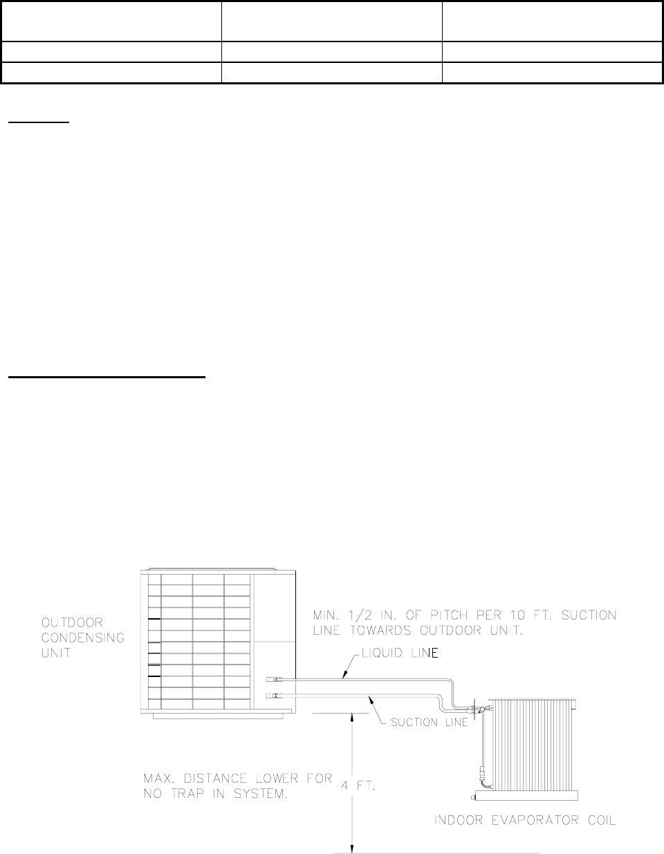
1. No traps in the suction line are necessary if the outdoor condensing unit is level with the
indoor evaporator coil or the indoor evaporator coil is 4 feet or less lower then the outdoor
condensing unit. Any horizontal runs of suction line should have minimum 1/2" pitch for
every 10 feet of line towards the outdoor condensing unit. See Figure F below.
All installations and services must be performed by qualified personnel.
14
Figure F
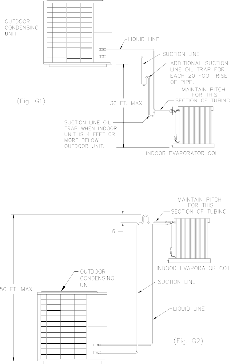
2. A trap is necessary in the suction line at the indoor evaporator coil if the indoor evaporator coil
is more than 4 feet below the outdoor condensing unit.
NOTE: Multiple suction line traps are recommended for longer or multiple horizontal lines.
(See Fig. G1).
An inverted trap should be installed on the horizontal suction line near the evaporator coil to
prevent liquid flood back to the compressor (See Fig. G2) if the indoor evaporator coil is
located 10’ or more above the condensing unit.
All installations and services must be performed by qualified personnel.
15
A gradual loop in the tubing can be constructed to take up the excess tubing if you find that too
much tubing has been brought onto a job. Such a loop MUST be kept in a horizontal (flat) plane
to avoid trapping the oil.
Refrigerant lines should be inserted into a suitable conduit or raceway when the lines are to be
buried between the building and the outdoor condensing unit. The lines must be provided with
sufficient protection and support to prevent damage when installed above ground.
When making "on the job" tubing, a solder of 95% tin, 5% antimony or any of the silver solders
such as SilFos, Phos-Copper, Easy-Flo 35 or 45, should be used. No attempt will be made here to
instruct proper soldering or brazing technique but it is necessary that the installer be properly
instructed in accordance with good existing practices.
All joints and fittings must be properly leak tested as per EPA guidelines after “on the job”
tubing has been made up. The line set and the evaporator coil must be evacuated to 29.96” Hg
(1000 microns) or lower when all joints and fittings are leak free. The service valves on the
condenser may then be opened to release the refrigerant to the system. Verify proper system
performance. See condensing unit manual for additional performance data.
HOW TO MEASURE SUPERHEAT (NOTE: A good electric resistance thermometer and
accurate suction pressure gauge are necessary).
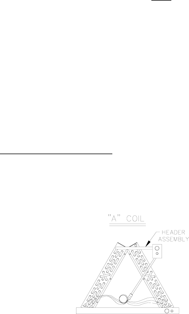
Superheat is measured by taking a temperature and pressure reading. See Figure I. The pressure
reading is gauged at the pressure port which is located on the suction service valve. The
temperature reading is taken at the evaporator coil on the header assembly in the 2:00 o'clock or
10:00 o'clock position with header assembly tube as the center of the clock.
Figure I

All installations and services must be performed by qualified personnel.
16
Read the temperature at header assembly to calculate the superheat. Then read the suction
pressure and then add the line loss of 2 lbs. for 25’ of tubing. Then convert pressure into
temperature.
Next, subtract the converted suction temperature from the measured coil header temperature and
the end result is the superheat.
EXAMPLE:
Measured Temp = 50oF
(Off header assembly at 10:00 or 2:00 position) See Figure I.
Measured Pressure = 71PSI + 2PSI = 73PSI which equates to a 43oF saturation temperature.
(Measured from pressure port)
(Listed temperature for measured pressure according to R-22 temperature scale on manifold
gauge or R-22 section of pressure temperature chart)
The difference equals the degrees superheat = 7oF
All 10 SEER models of Thermo Pride air conditioners should have a 3oF to 7oF superheat at an
85oF to 95oF outdoor temperature and a 70oF to 80oF indoor temperature. The superheat
temperature will not be accurate if the indoor temperature is not within the 70oF to 80oF range.
Therefore, an indoor temperature within the above range must be achieved before an accurate
superheat can be measured.
MEASURING TEMPERATURE DROP ACROSS THE “A” COIL:
The temperature drop across the coil should be around 15oF to 20oF difference between inlet and
outlet air. This should be measured as close to the air handler as possible, to eliminate duct
losses.
ELECTRICAL
All wiring must conform to the provisions of local codes or in the absence of local codes with the
provisions of the National Electrical Code, ANSI/NFPA No. 70-Latest Edition and this
instruction manual. Equivalent type wire must be used if any of the original wire supplied with
the unit needs to be replaced A 10 amp time delayed fuse or circuit breaker is recommended.
NOTE: Condensing unit is not included in above amp rating.
All installations and services must be performed by qualified personnel.
17
The following points must be checked by the installer and/or electrician before the air
conditioning system is started:
1. Check every electrical connection of "PUSH-ON" or "SCREW-ON" terminals to ensure it is
on tightly on its proper post.
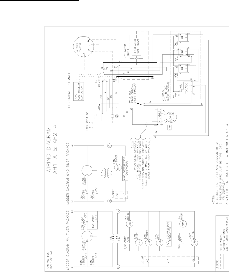
2. Review wiring diagram for proper routing.
A loose terminal will cause poor flow of electrical power and result in very high current draw.
This can lead to blown fuses or burned wires.
UA ADAPTER CABINET
The UA adapter cabinet is designed to be used in conjunction with the AH AIR HANDLER to
allow a free standing (vertical discharge) installation. The UA cabinet is shipped completely
assembled and ready for installation.
All installations and services must be performed by qualified personnel.
18
A return air opening can be cut in any of the four sides or the bottom of the UA cabinet. The AH
AIR HANDLER is then placed on the UA adapter cabinet, inlet side down. The AH rests on the
support angles of the UA adapter cabinet. The UA cabinet is equipped with a permanent
washable air filter.
When using the UA air handler, the coil drain and coil drain pan must be utilized in place of the
primary drain and primary drain pan found in the air handler.
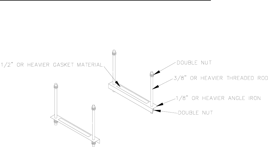
AH AIR HANDLER RECOMMENDED SUSPENSION PROCEDURE
The detail below is the proper and safest way to suspend the AH. These components should be
easily found at your local hardware store.
All installations and services must be performed by qualified personnel.
19
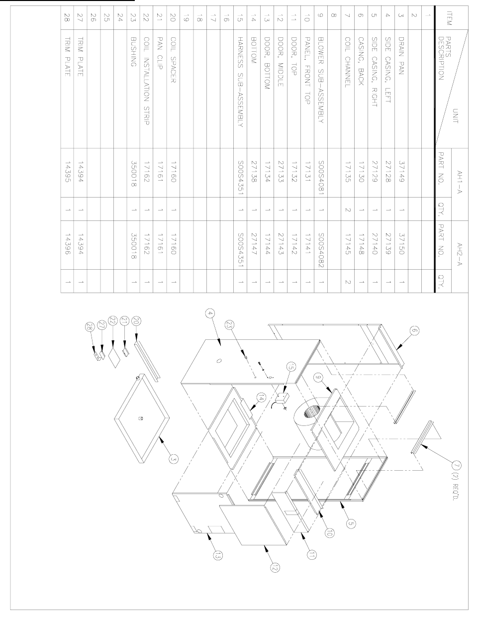
REPLACEMENT PARTS
All installations and services must be performed by qualified personnel.
20
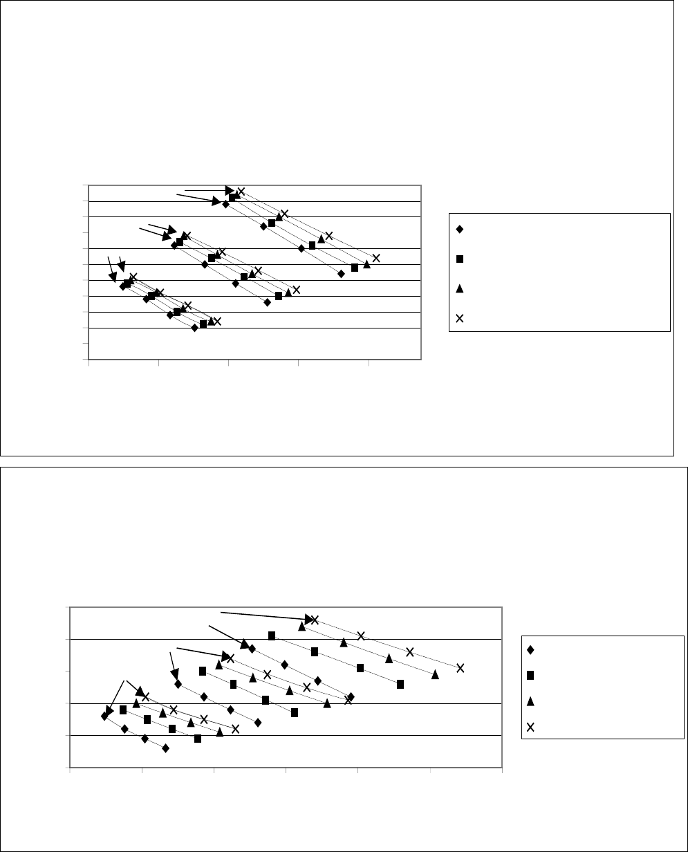
AH2-A Air Handler with HC2-A Hydronic Coil
Outlet Air Temerature vs. Heating Capacity
(GPM,PSI,Coil Drop)
90
95
100
105
110
115
120
125
130
135
140
145
40 60 80 100 120
Heating Capacity (Mbtuh)
Air Temp. (deg. F)
7 GPM(.65,1.5' H2O)
8 GPM(.95,2.2' H2O)
9 GPM(1.17,2.7' H2O)
10 GPM(1.34,3.1' H2O)
140 F Inlet Water Temp.
160 F Inlet Water Temp.
180 F Inlet Water Temp.
l
Low Speed
l
Medium Low
Medium High
High
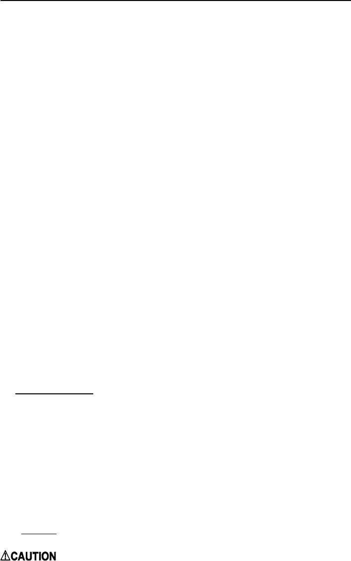
AH1-A Air Handler with HC1-A Hydronic Coil Outlet Air
Temperature vs. Heating Capacity
(GPM,PSI,Coil Drop)
90
100
110
120
130
140
30 40 50 60 70 80 90
Heating Capacity (Mbtuh)
Air Temp. (deg. F)
3 GPM(.476,1.1' H2O)
4 GPM(.823,1.9' H2O)
5 GPM(1.25,2.9' H2O)
6 GPM(1.65,3.8' H2O)
140 F Inlet Water Temp.
160 F Inlet Water Temp.
180 F Inlet Water Temp. Low Speed
Medium Low
Medium High
High
