Thermo Scientific XL3 RFID Module User Manual XL3 8 0
Thermo Scientific, Inc. RFID Module XL3 8 0
UserManual.wiki
>
Thermo Scientific
>
XL3 User Manual
>
User Manual.pdf
Contents
1.
User Manual (Statements).pdf
2.
User Manual.pdf
User Manual.pdf
Navigation menu
Upload a User Manual
Namespaces
Wiki Guide
HTML
PDF
Info
Views
User Manual
Discussion / Help
Navigation


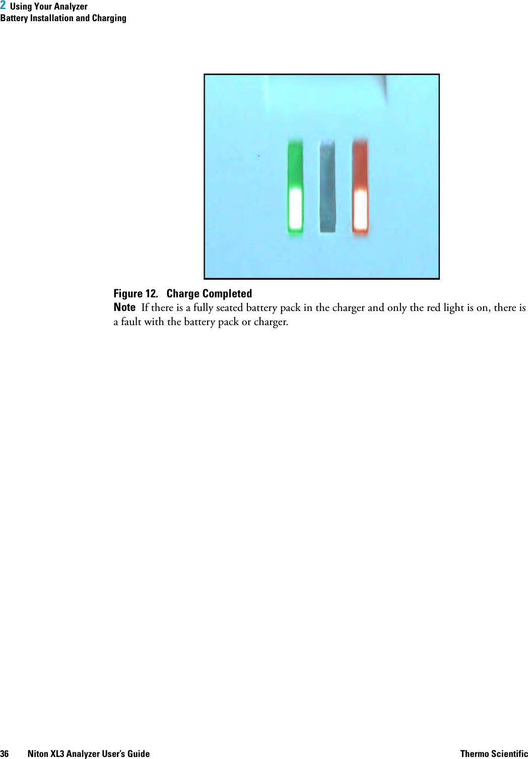
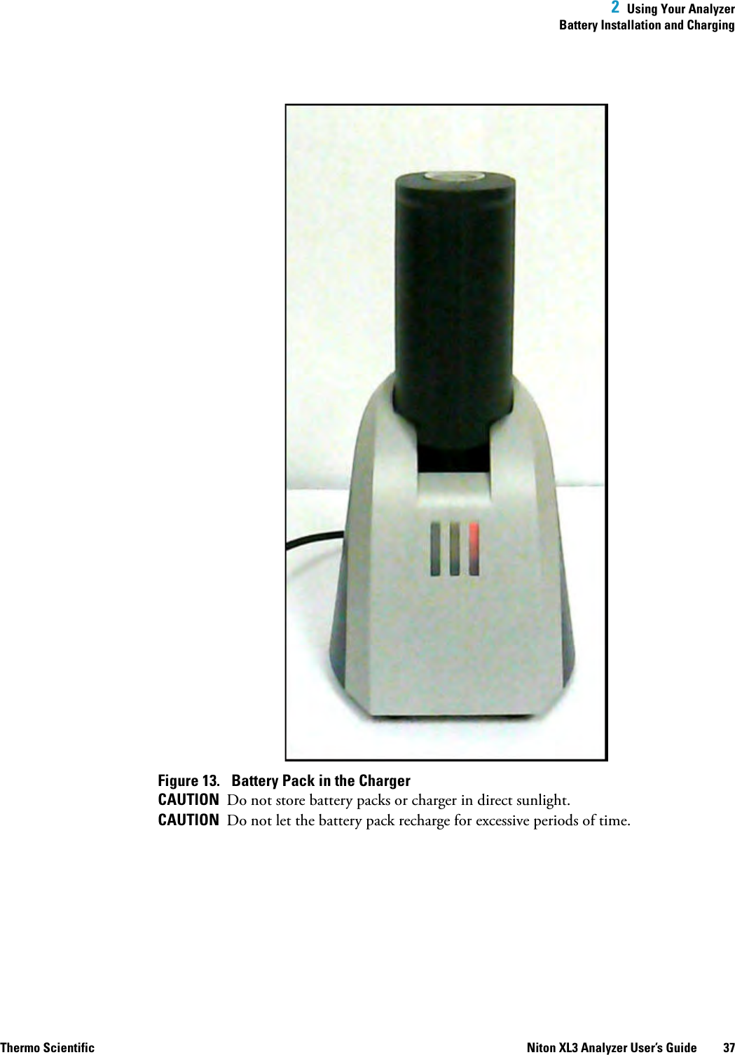
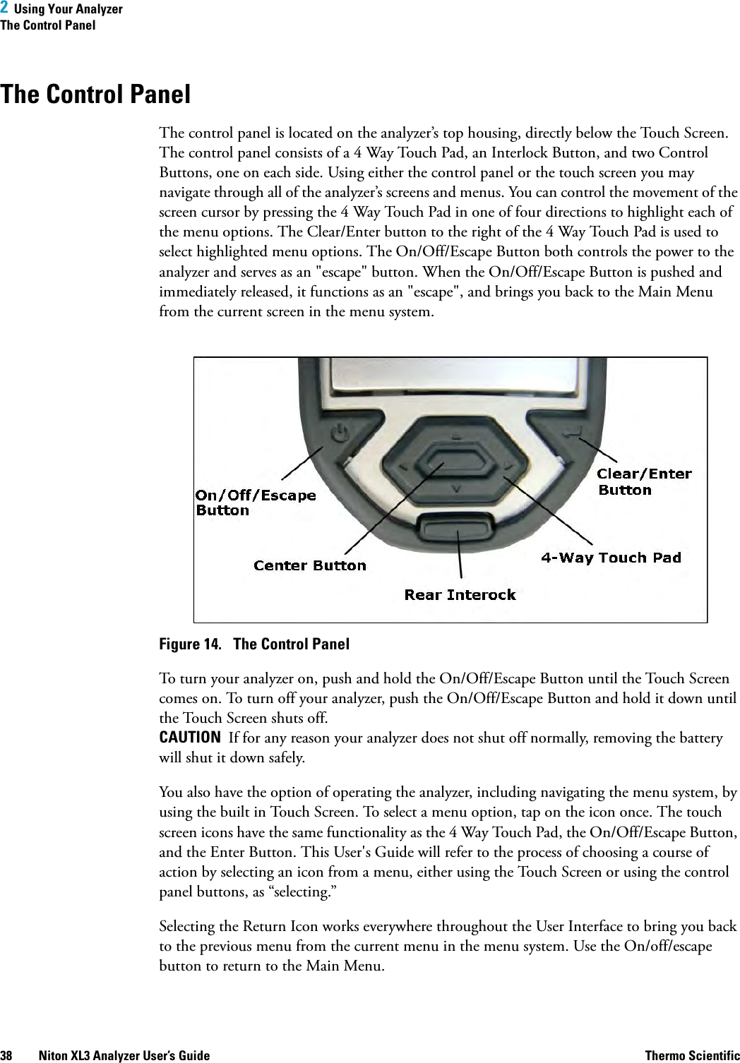

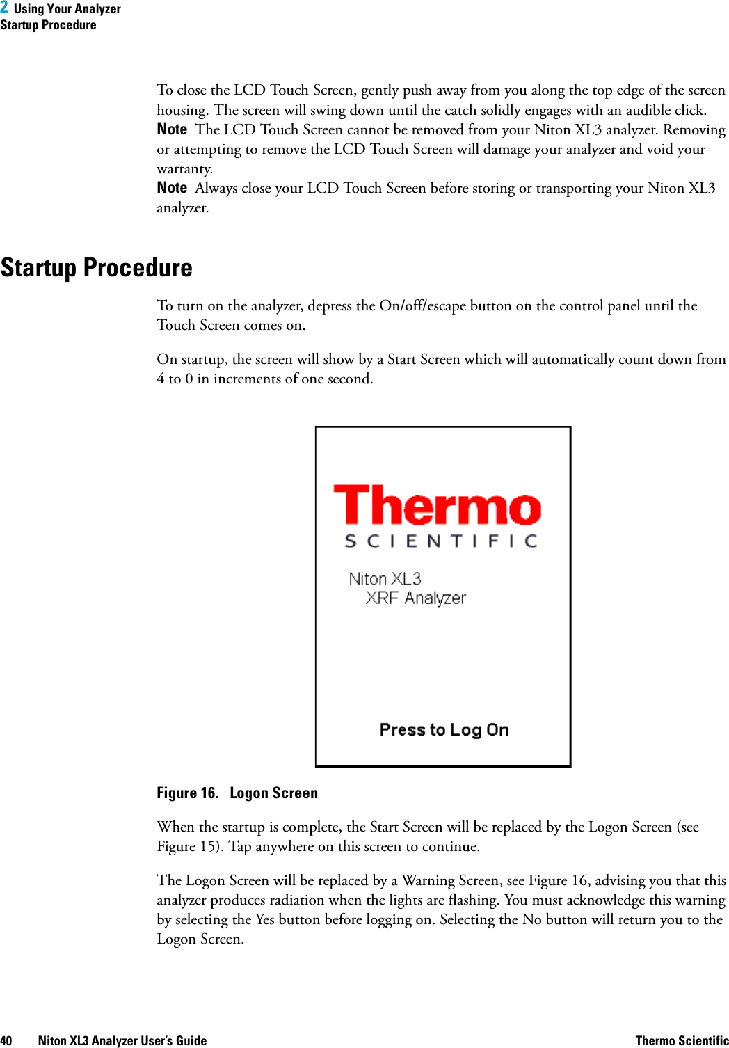
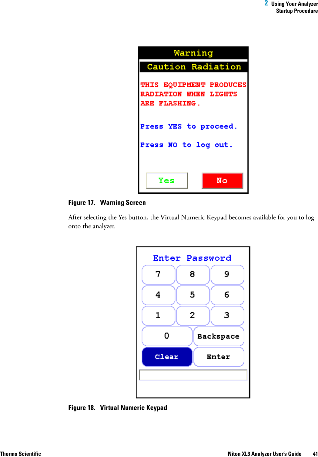
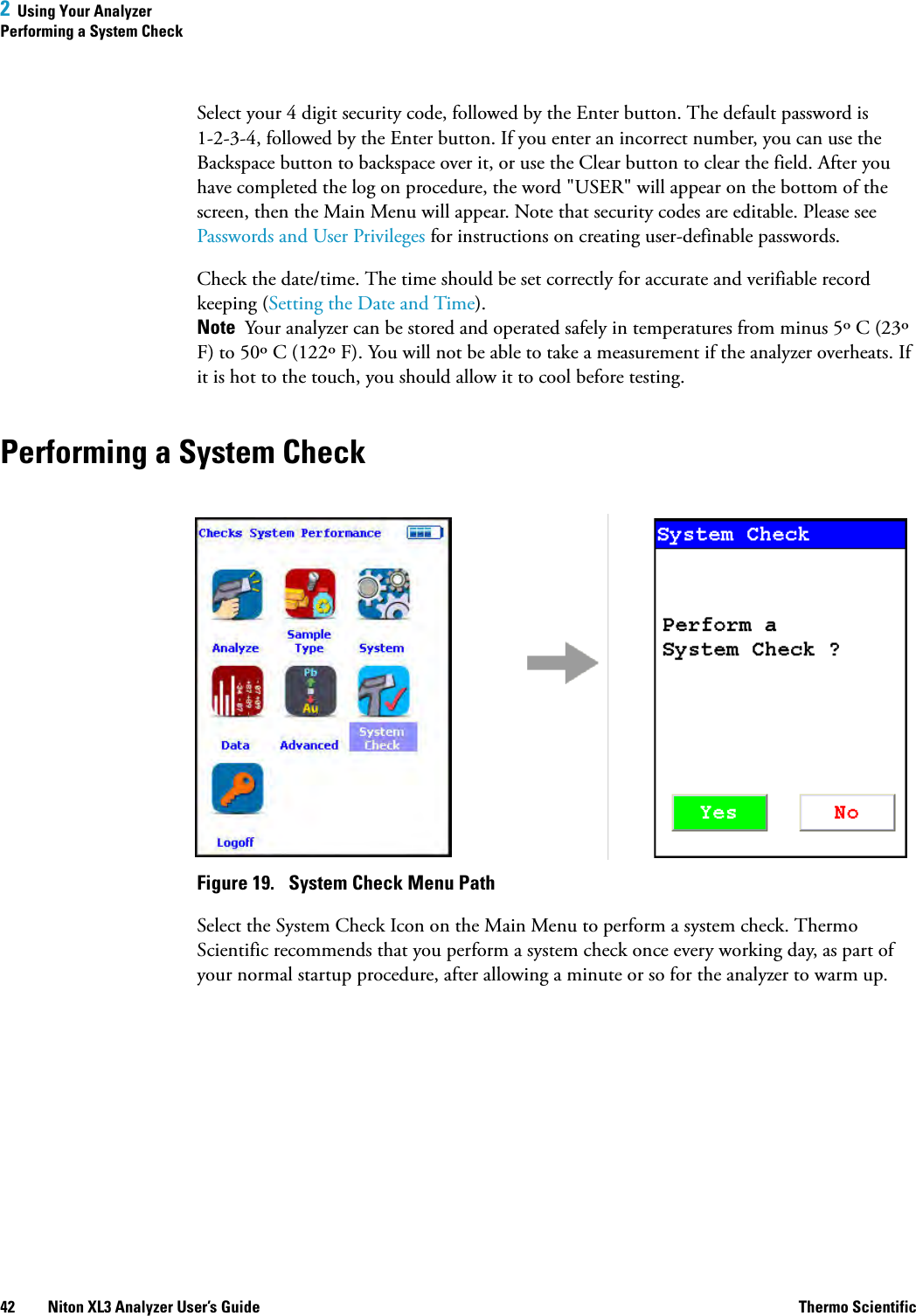
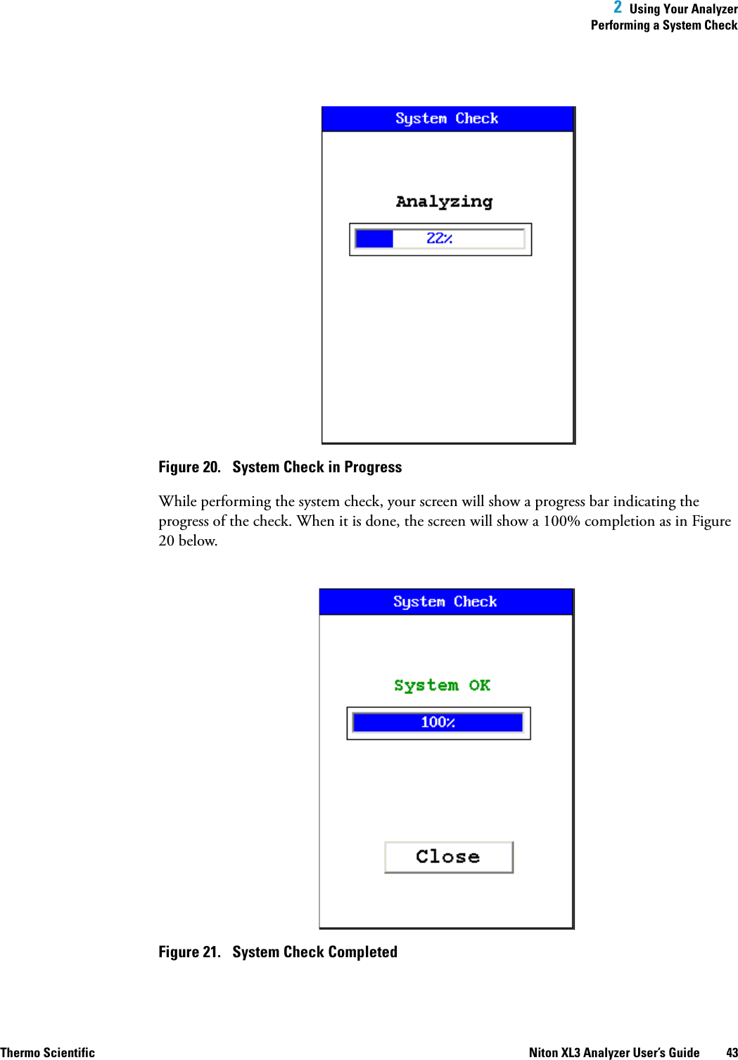

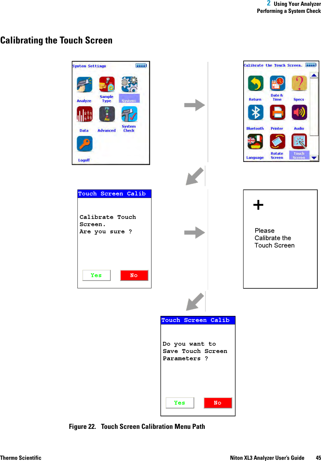
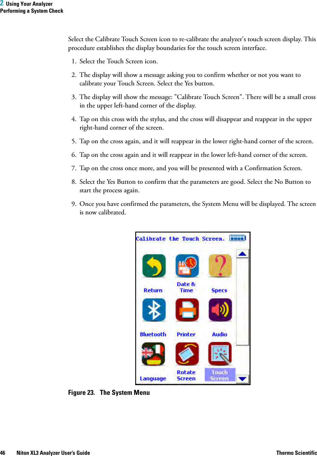

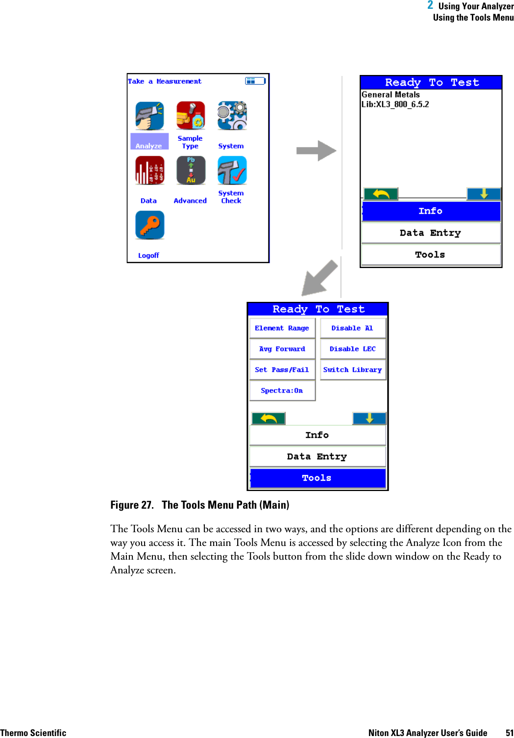
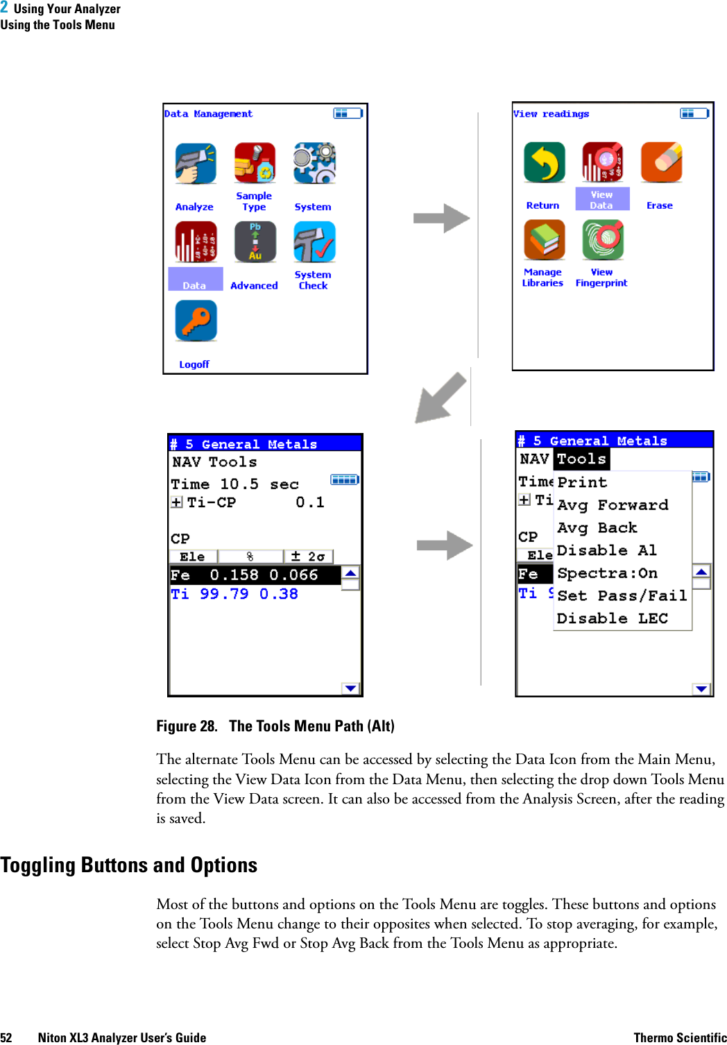
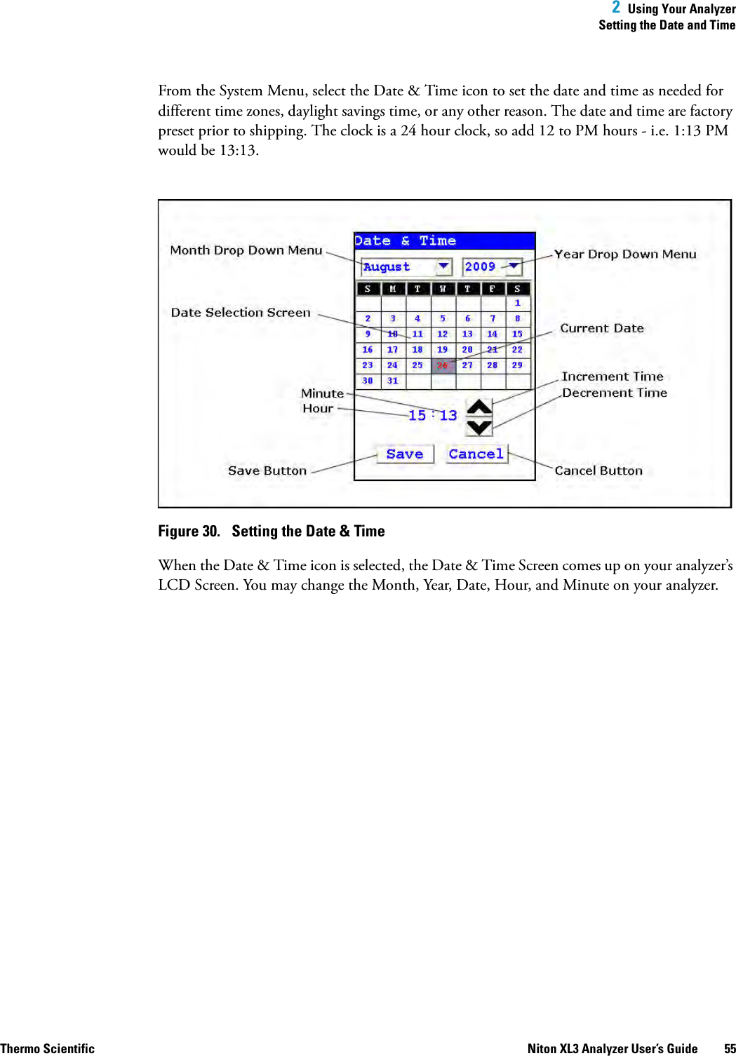
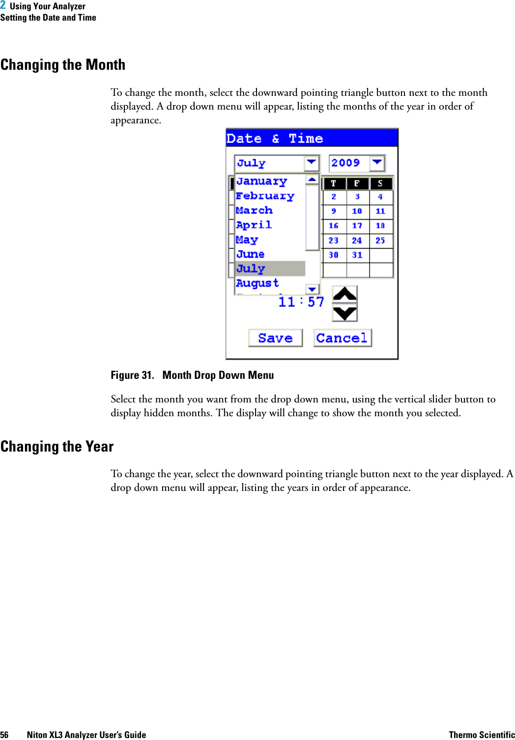
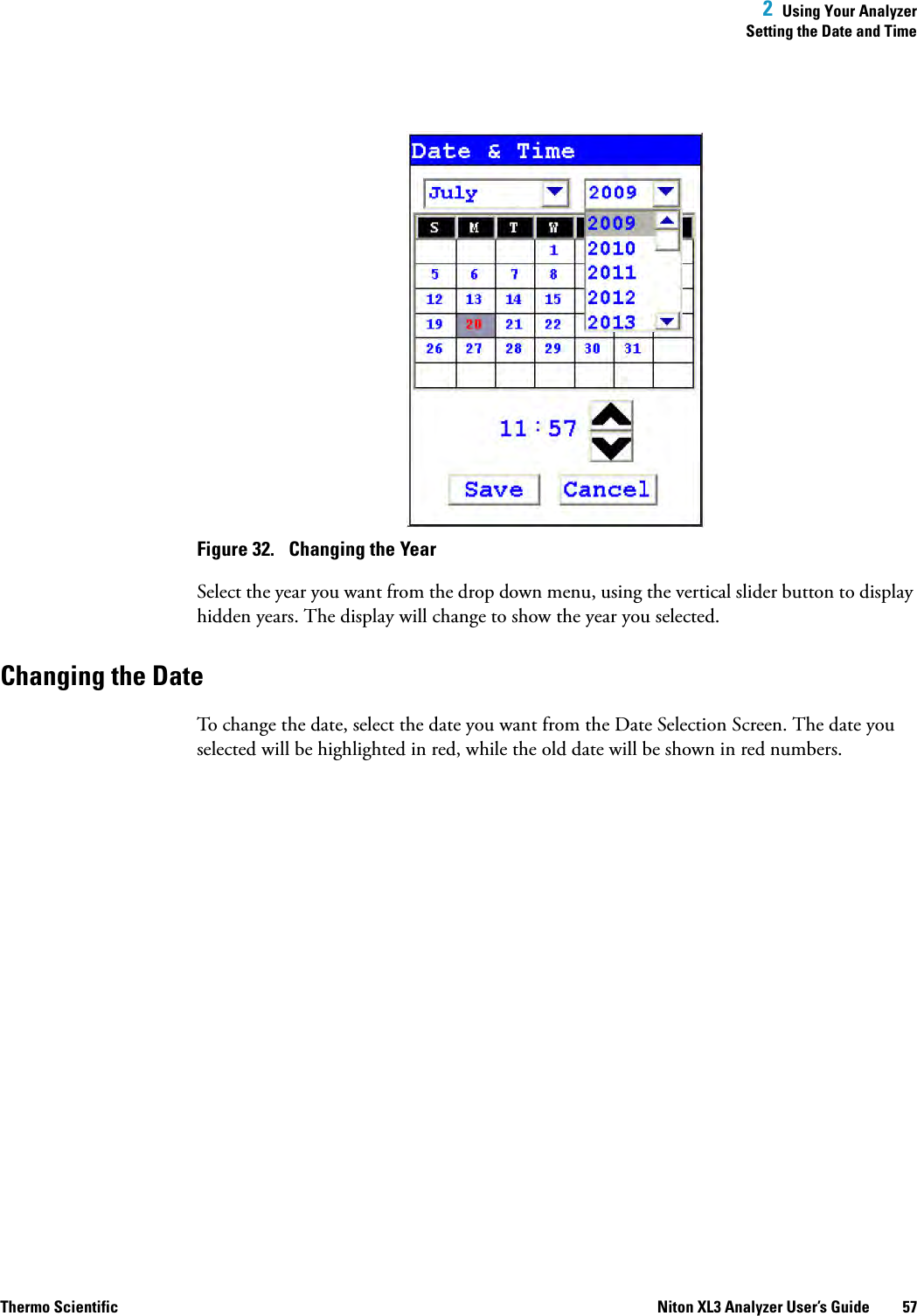
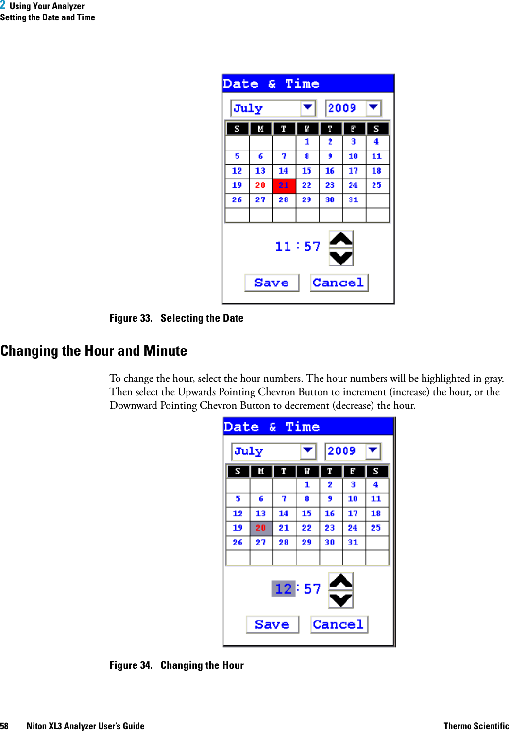
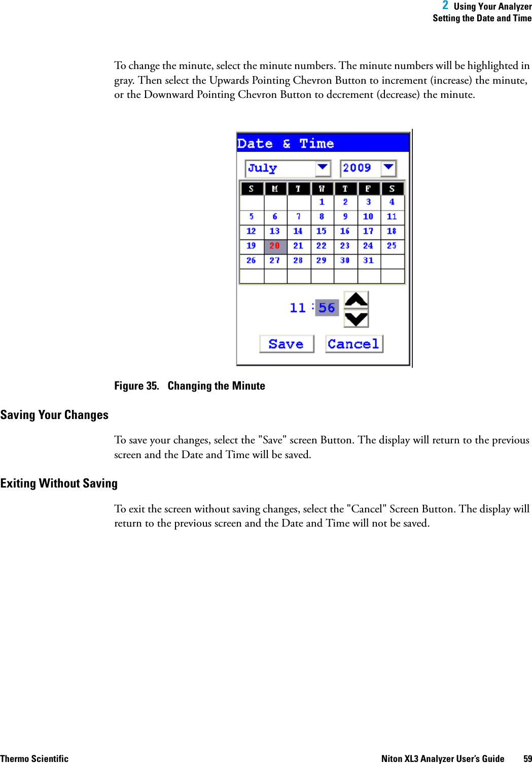
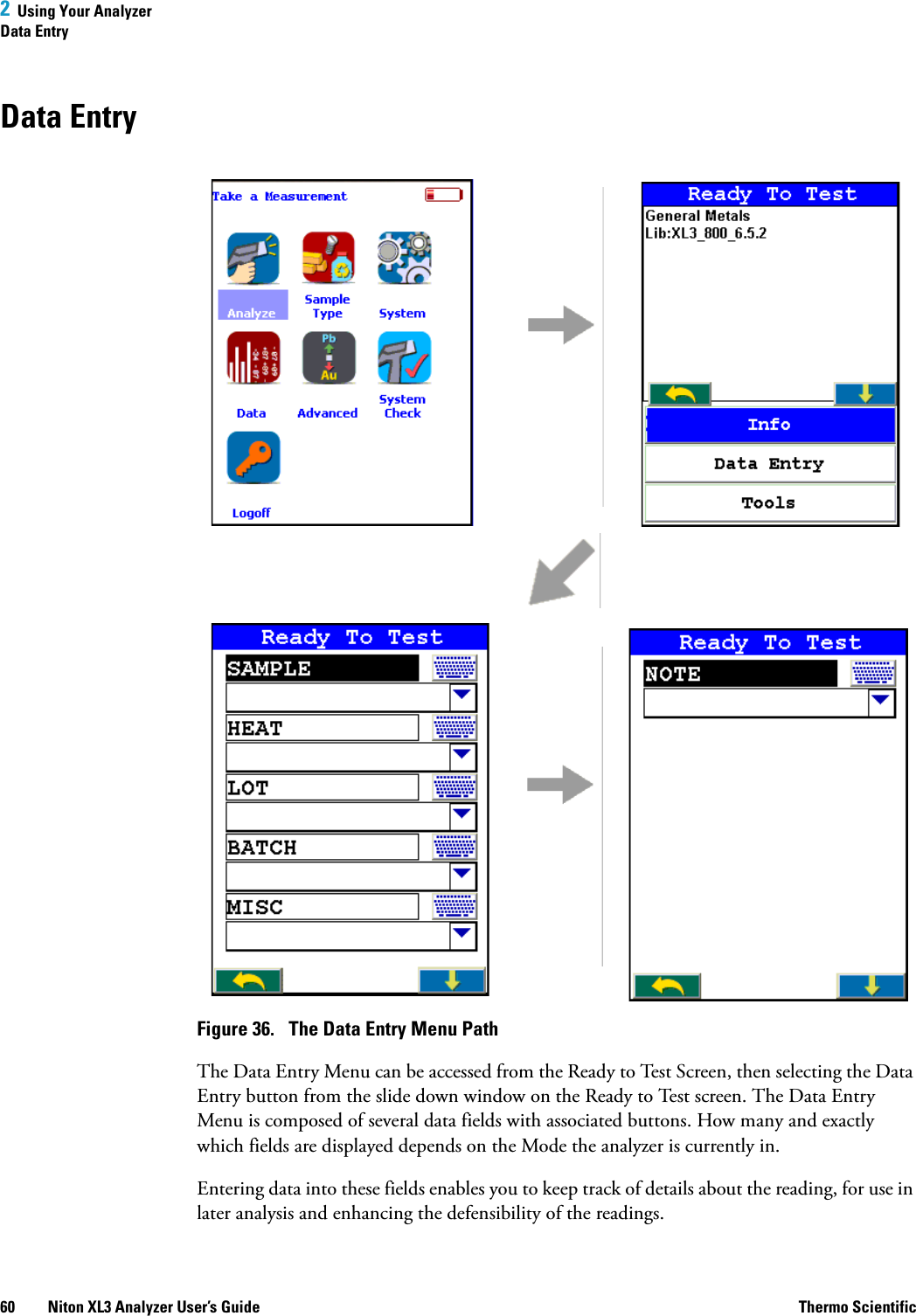
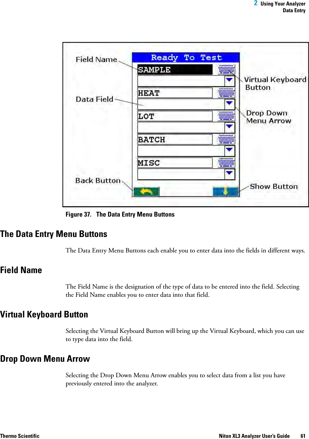
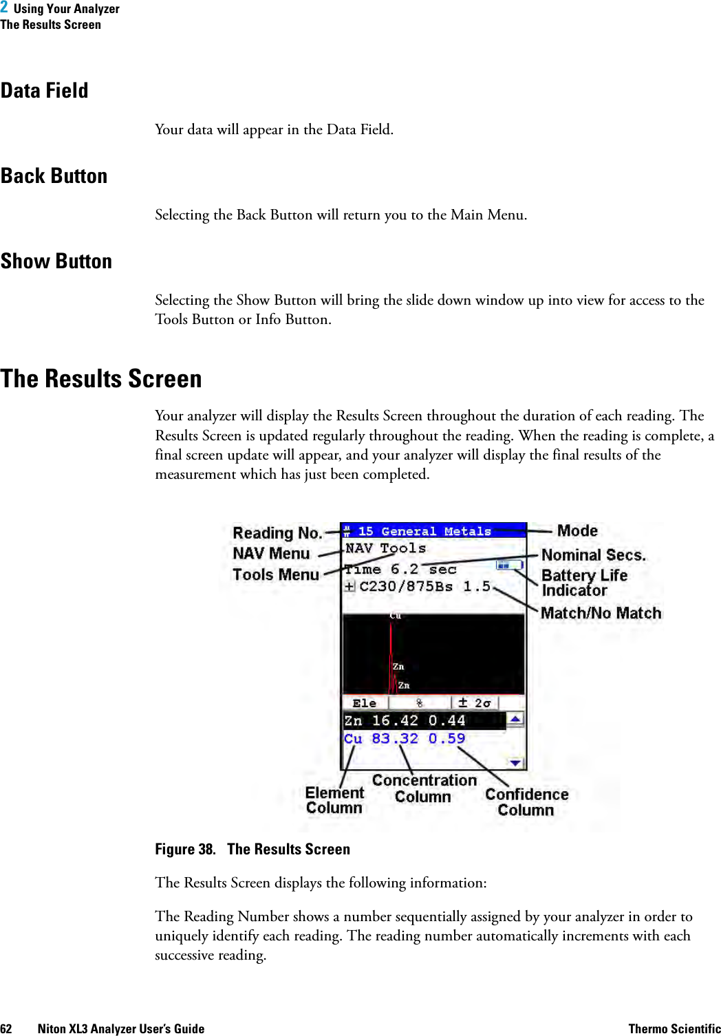
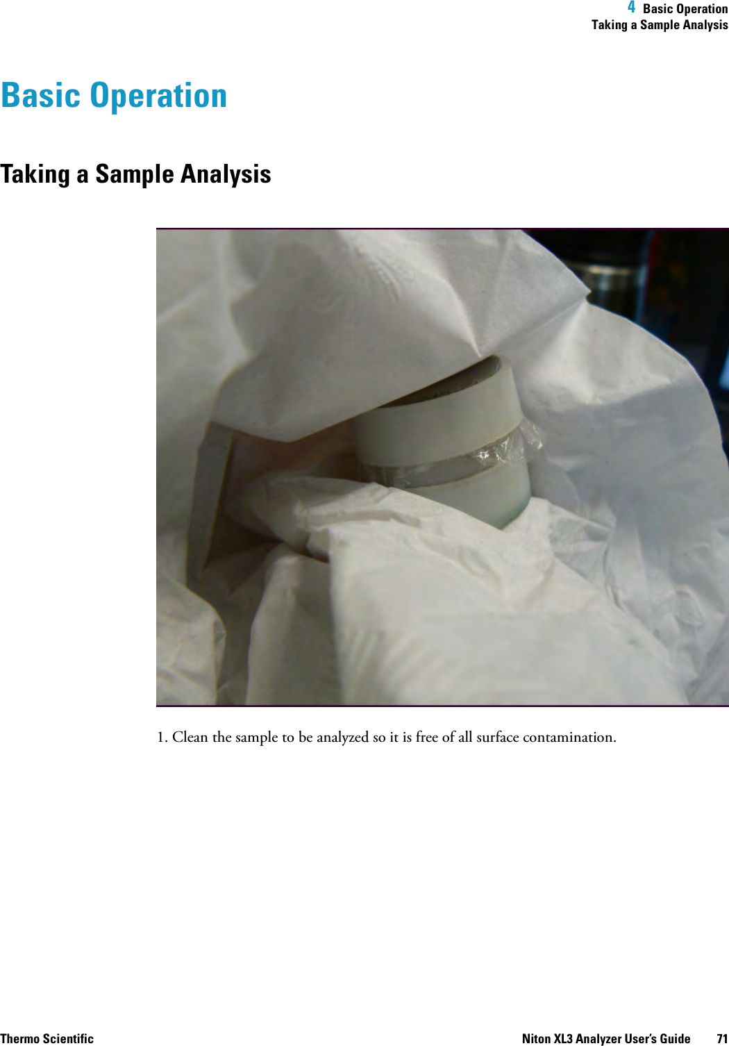
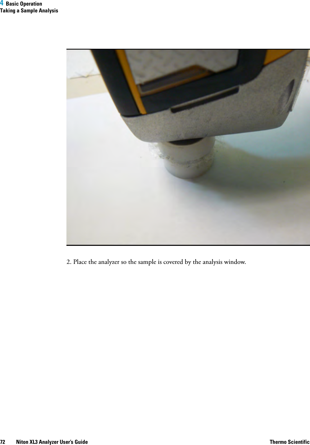
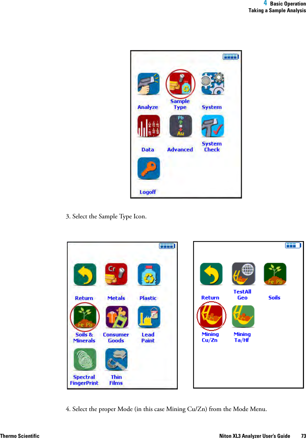
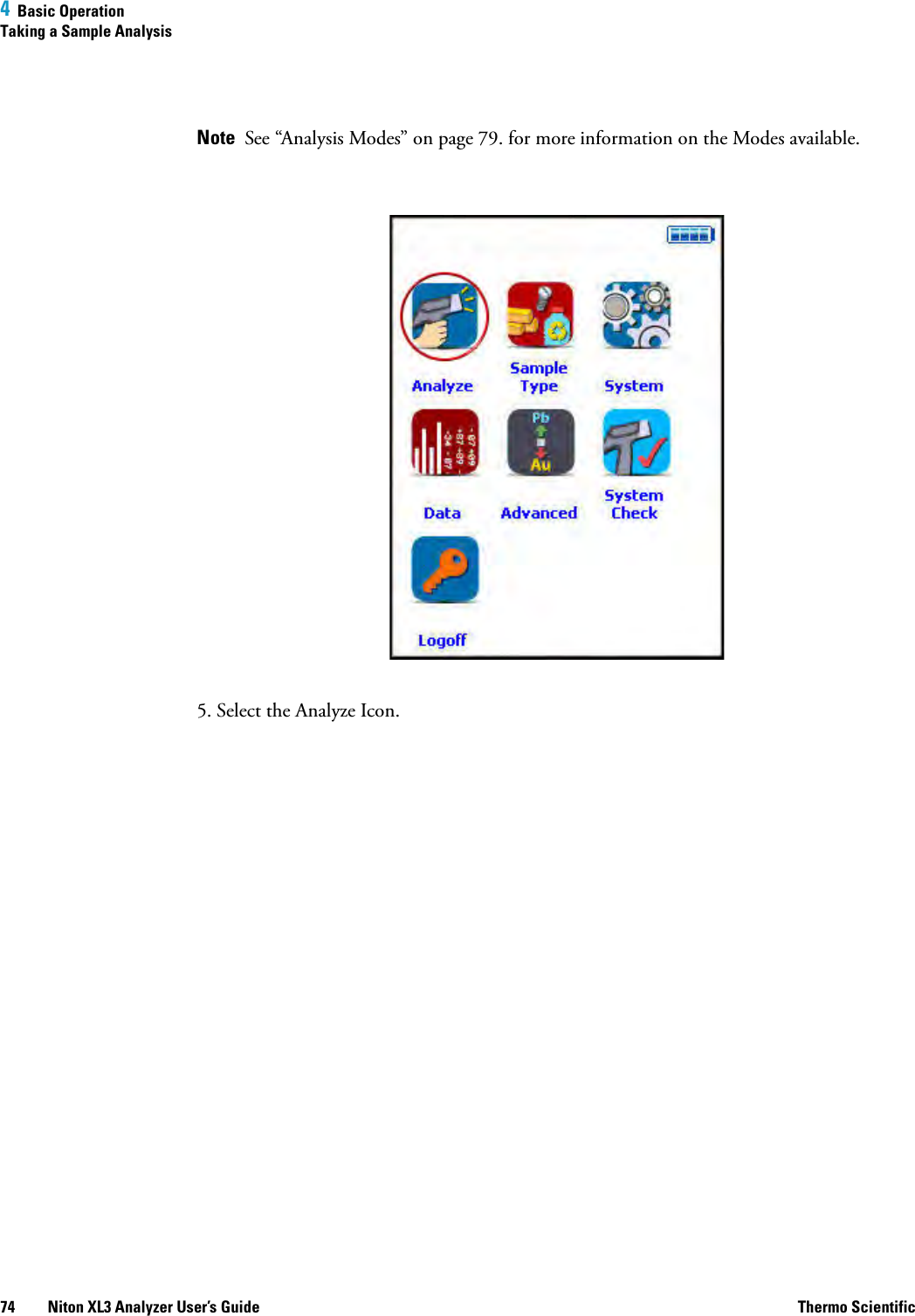
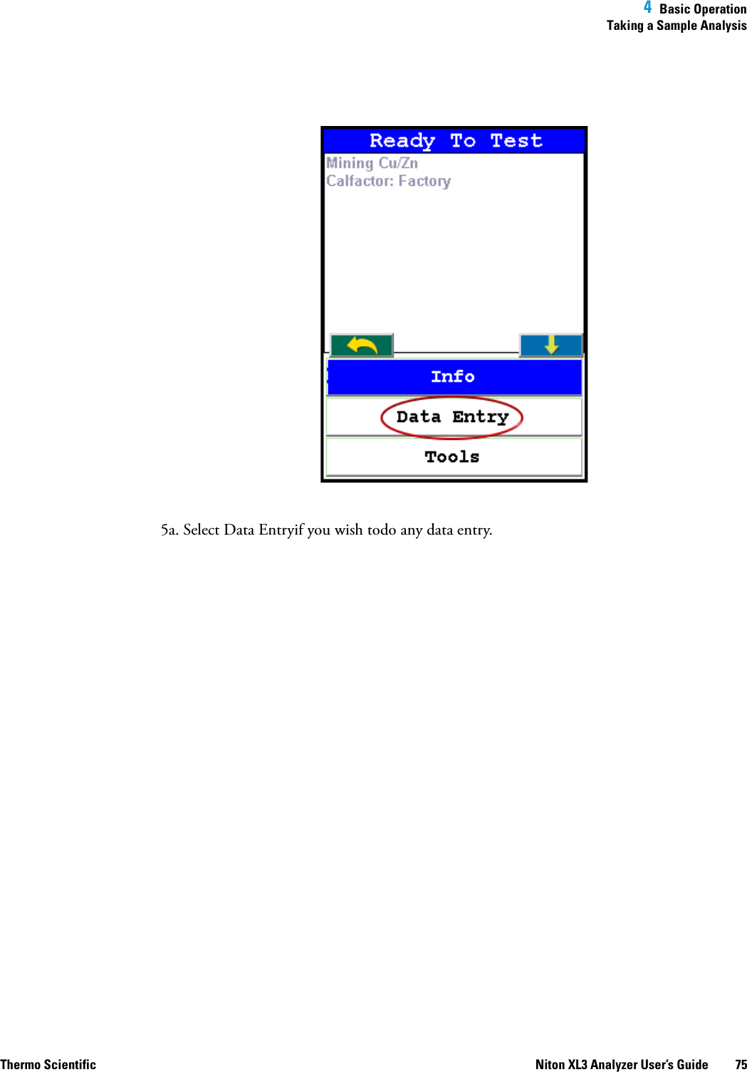
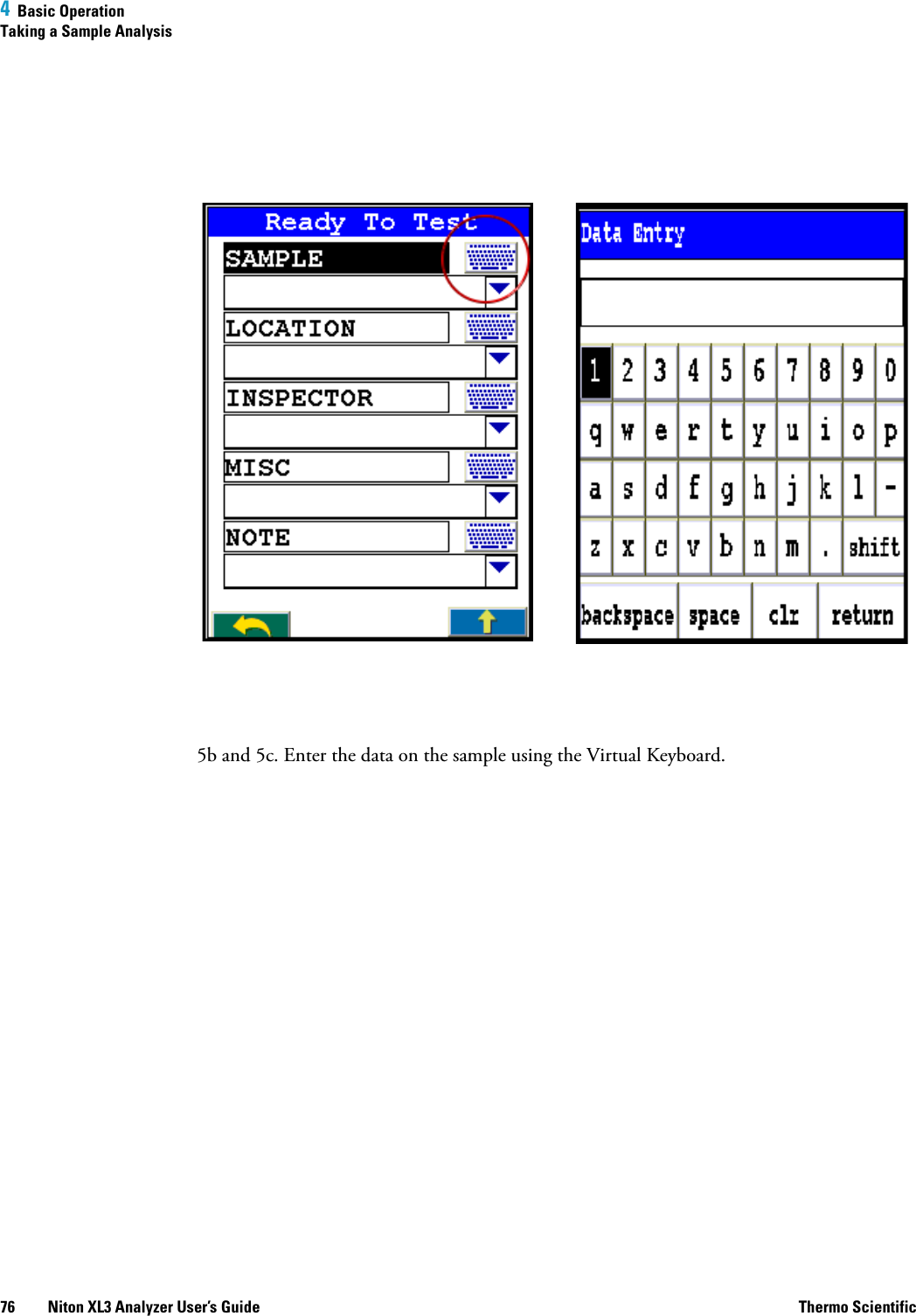
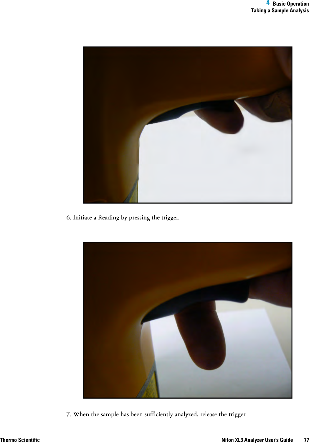
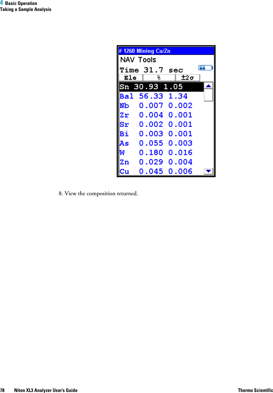
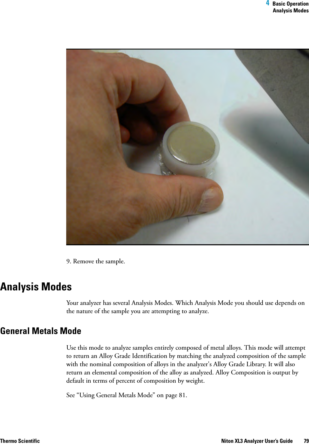


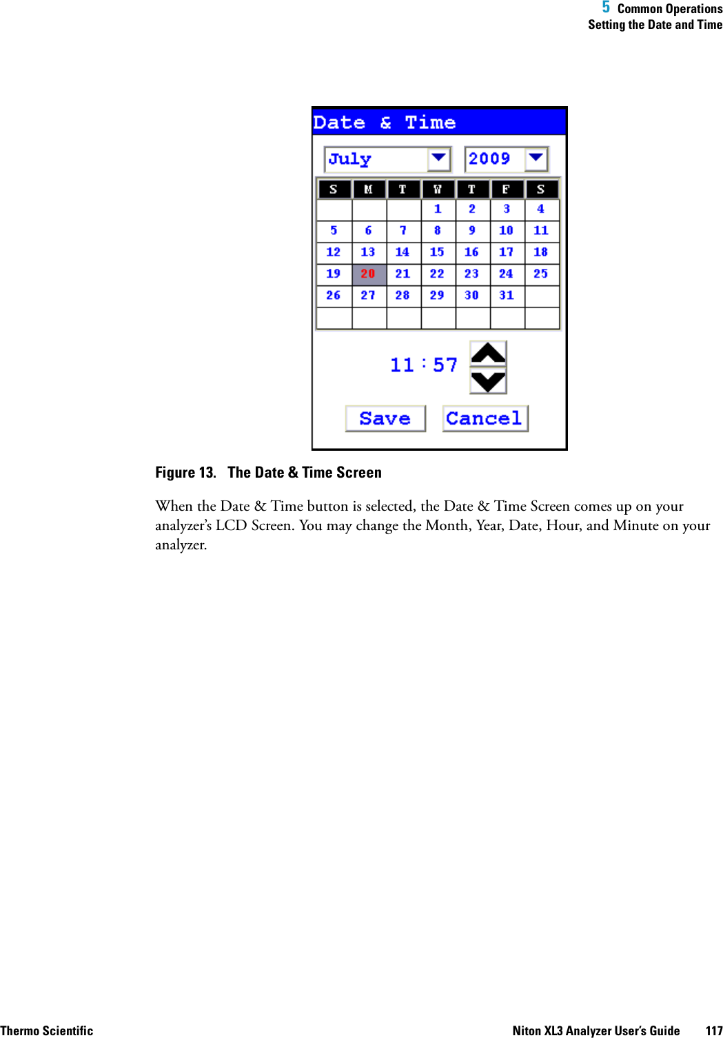
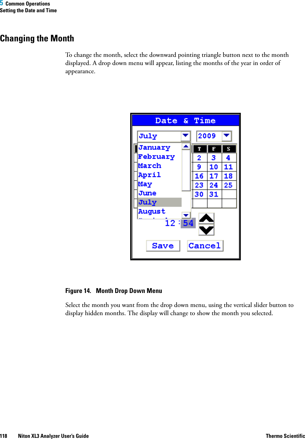
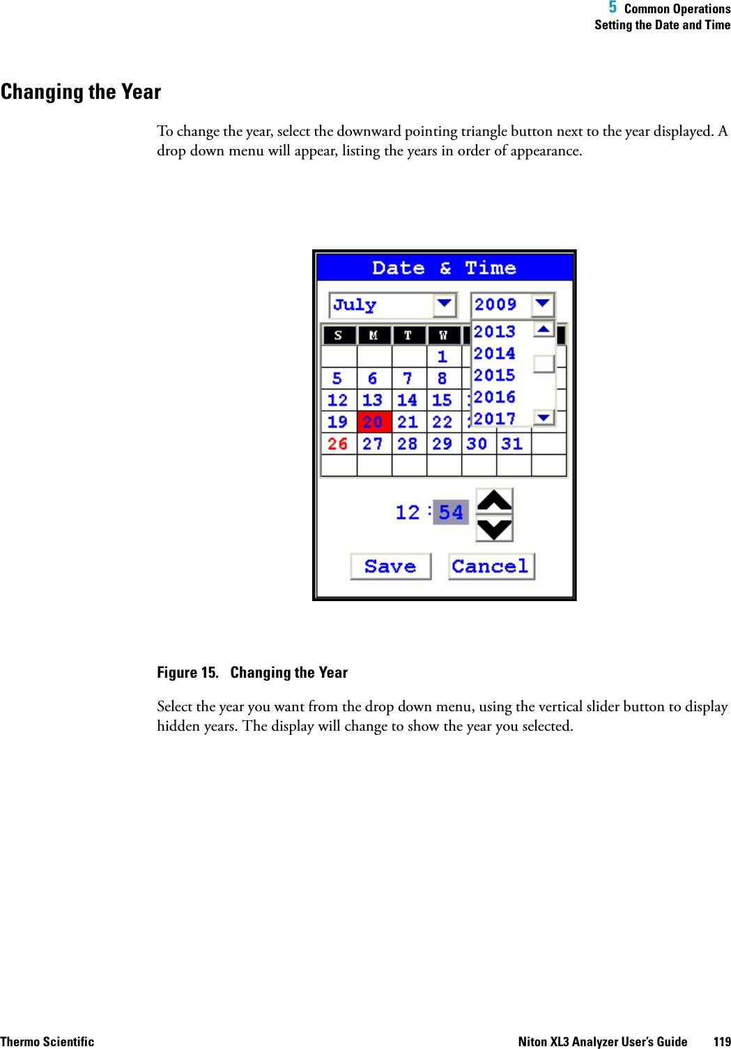
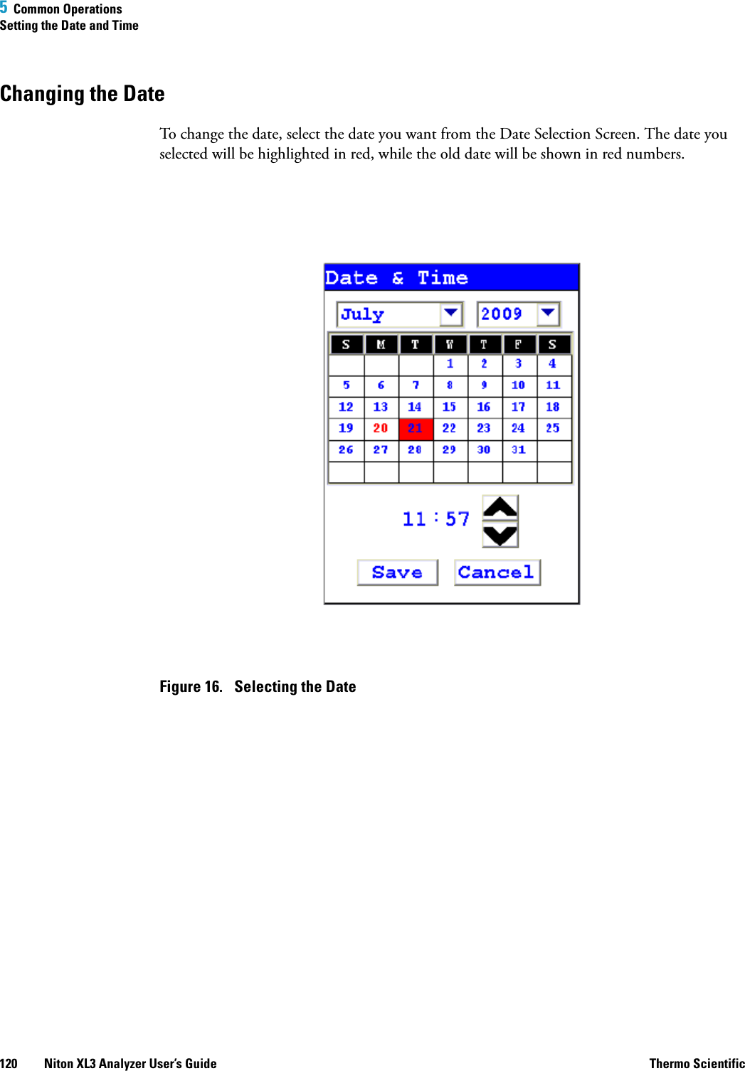
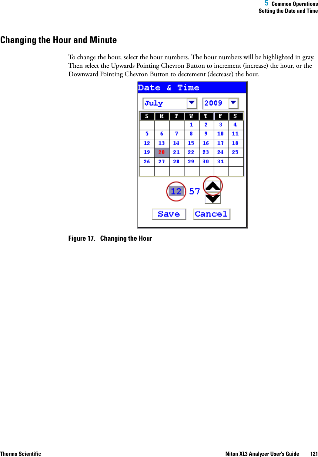
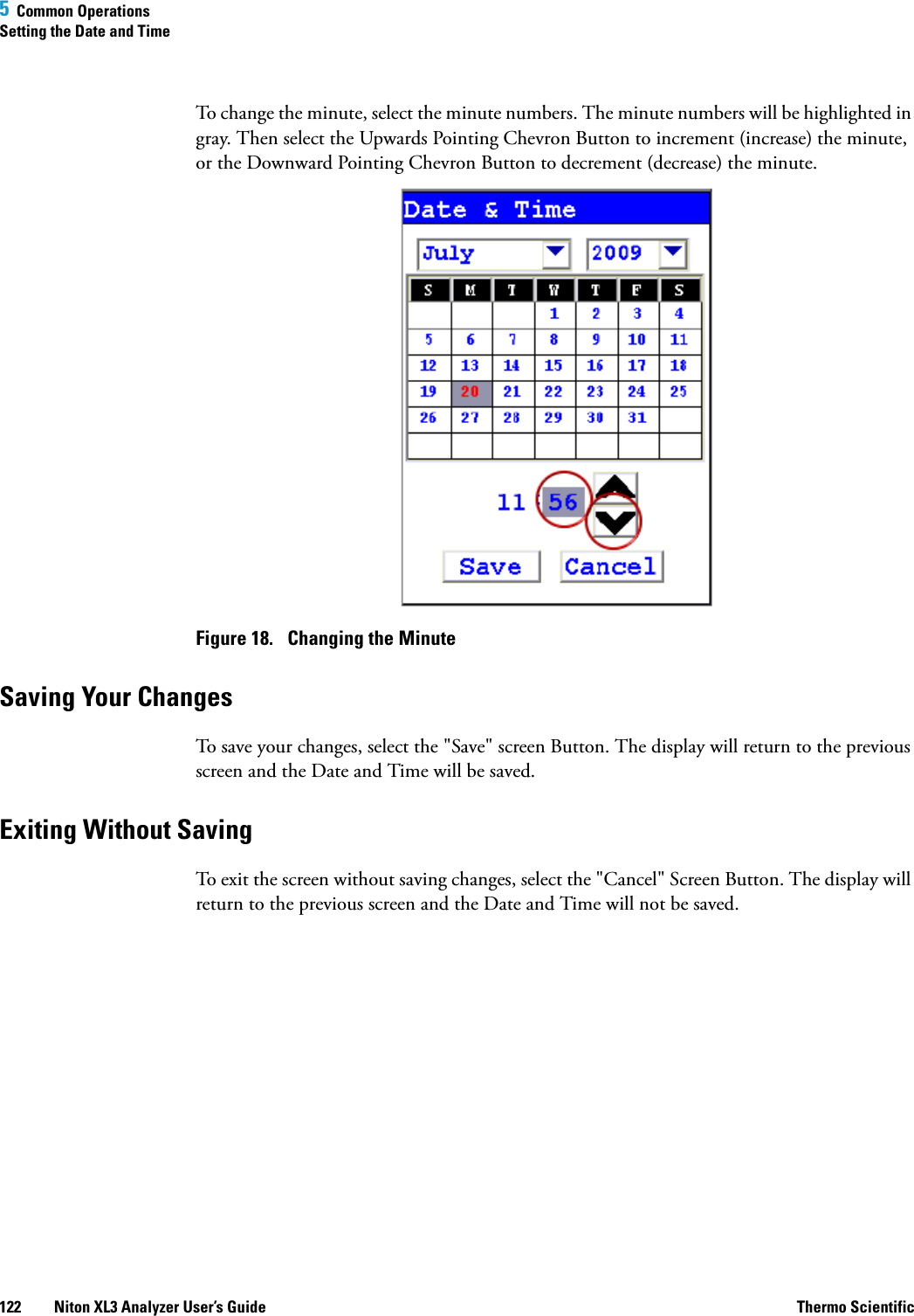
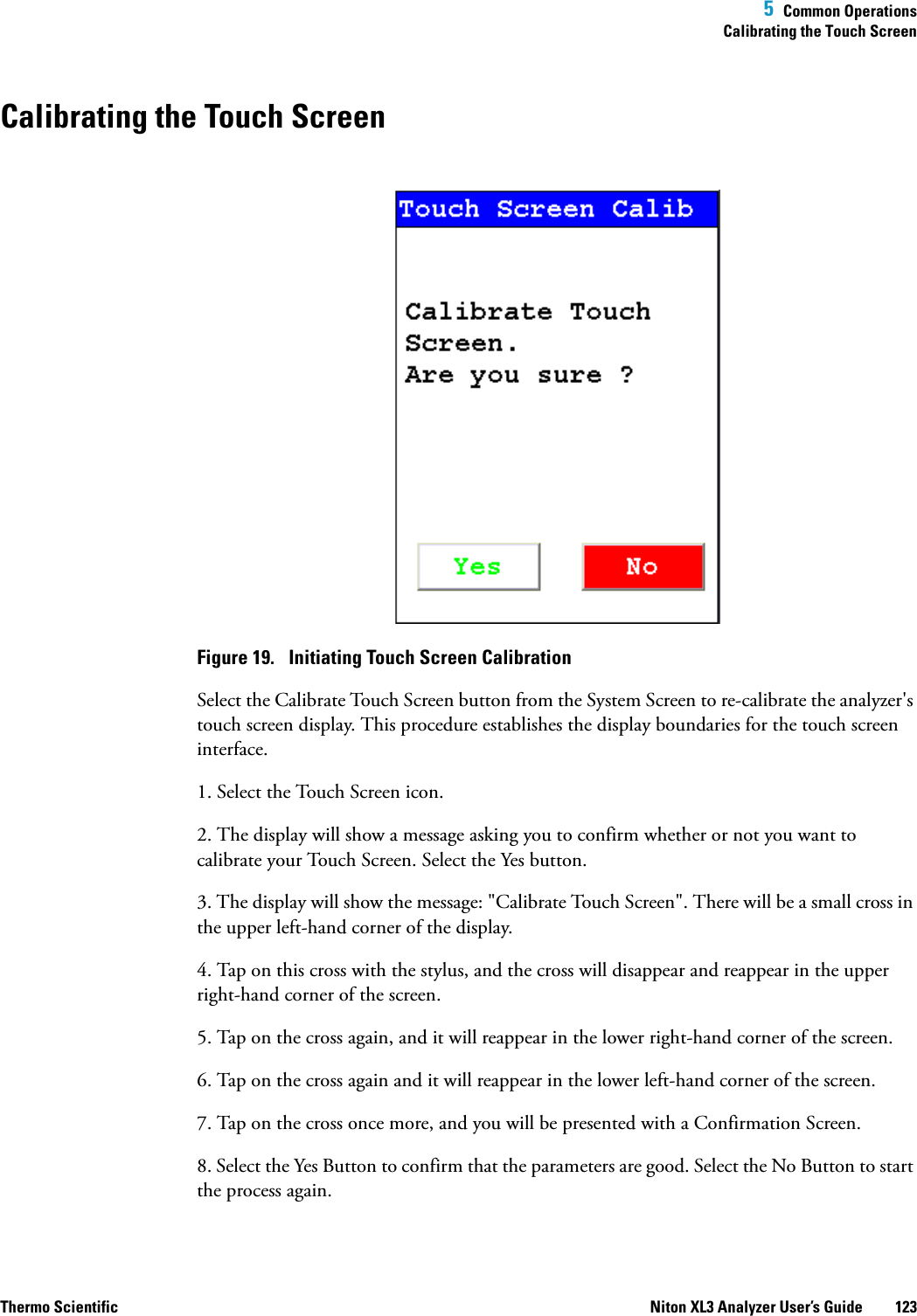
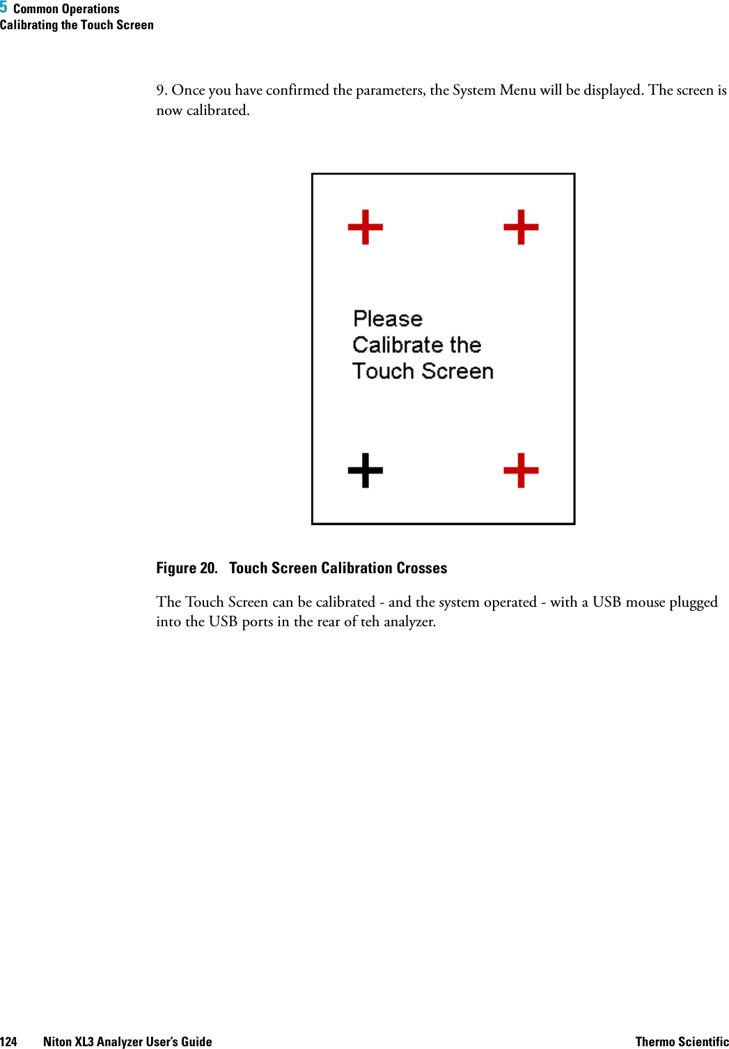
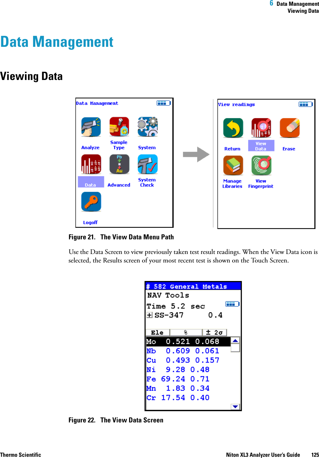
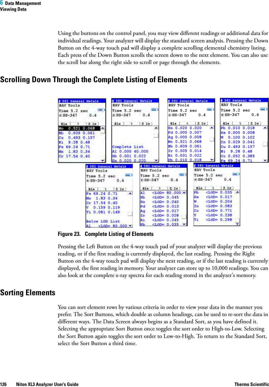
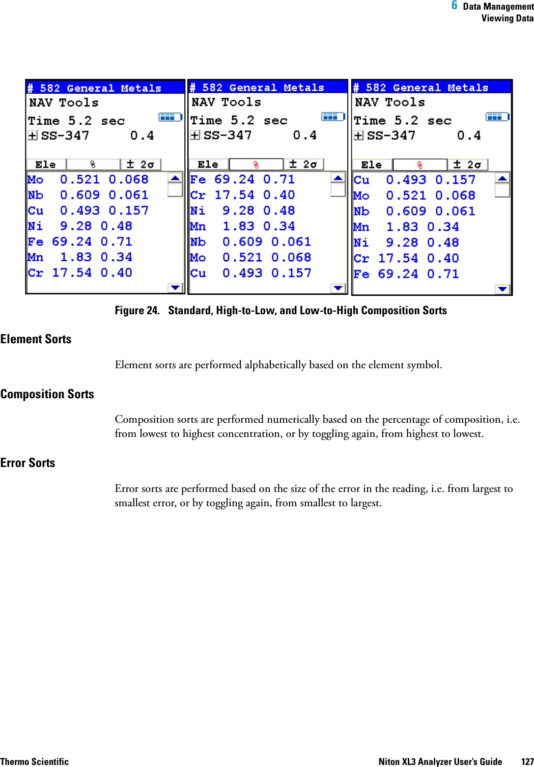
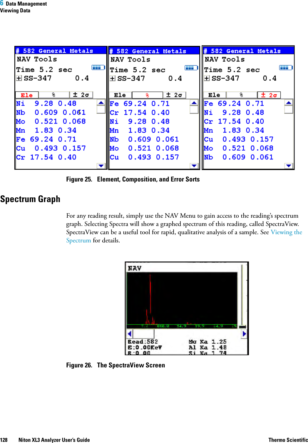
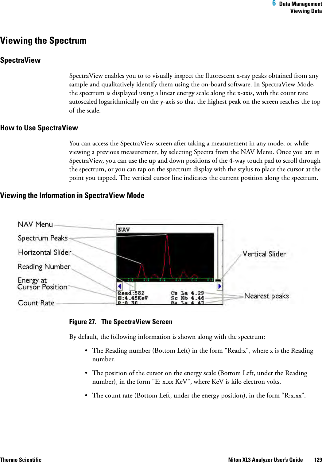
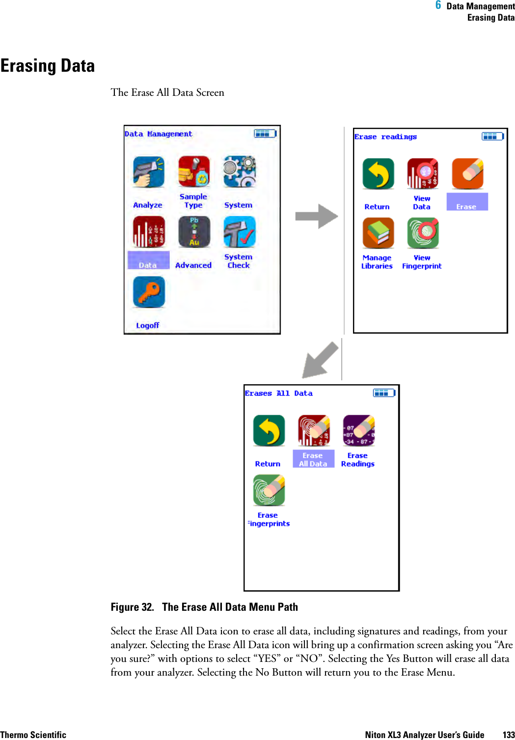
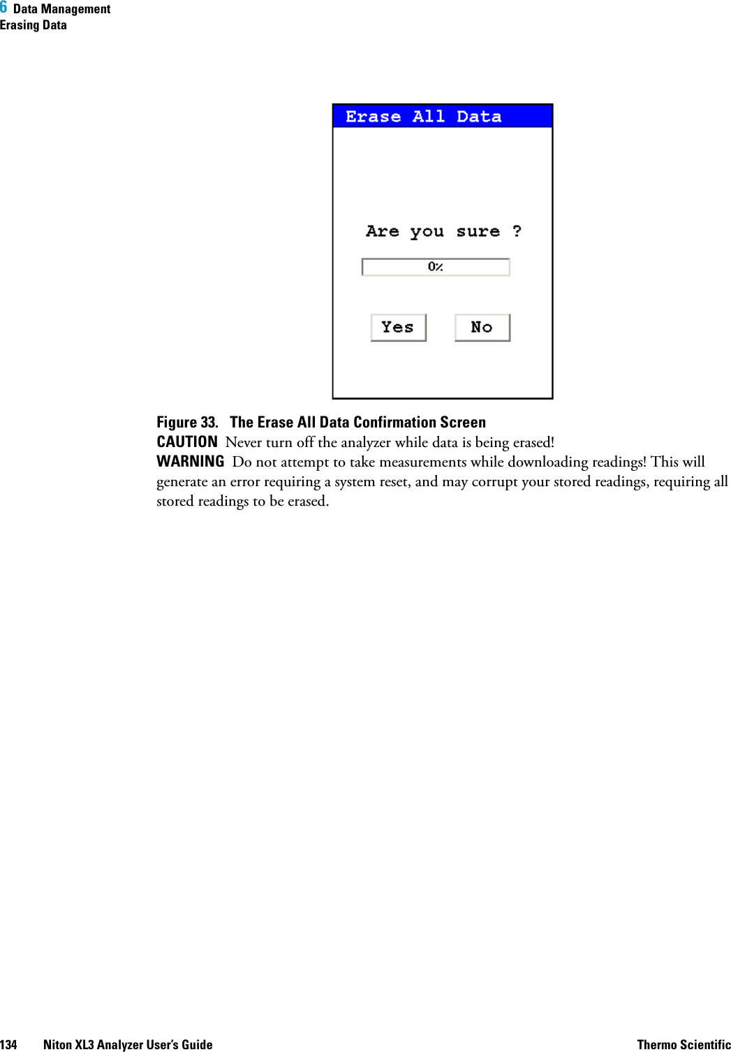
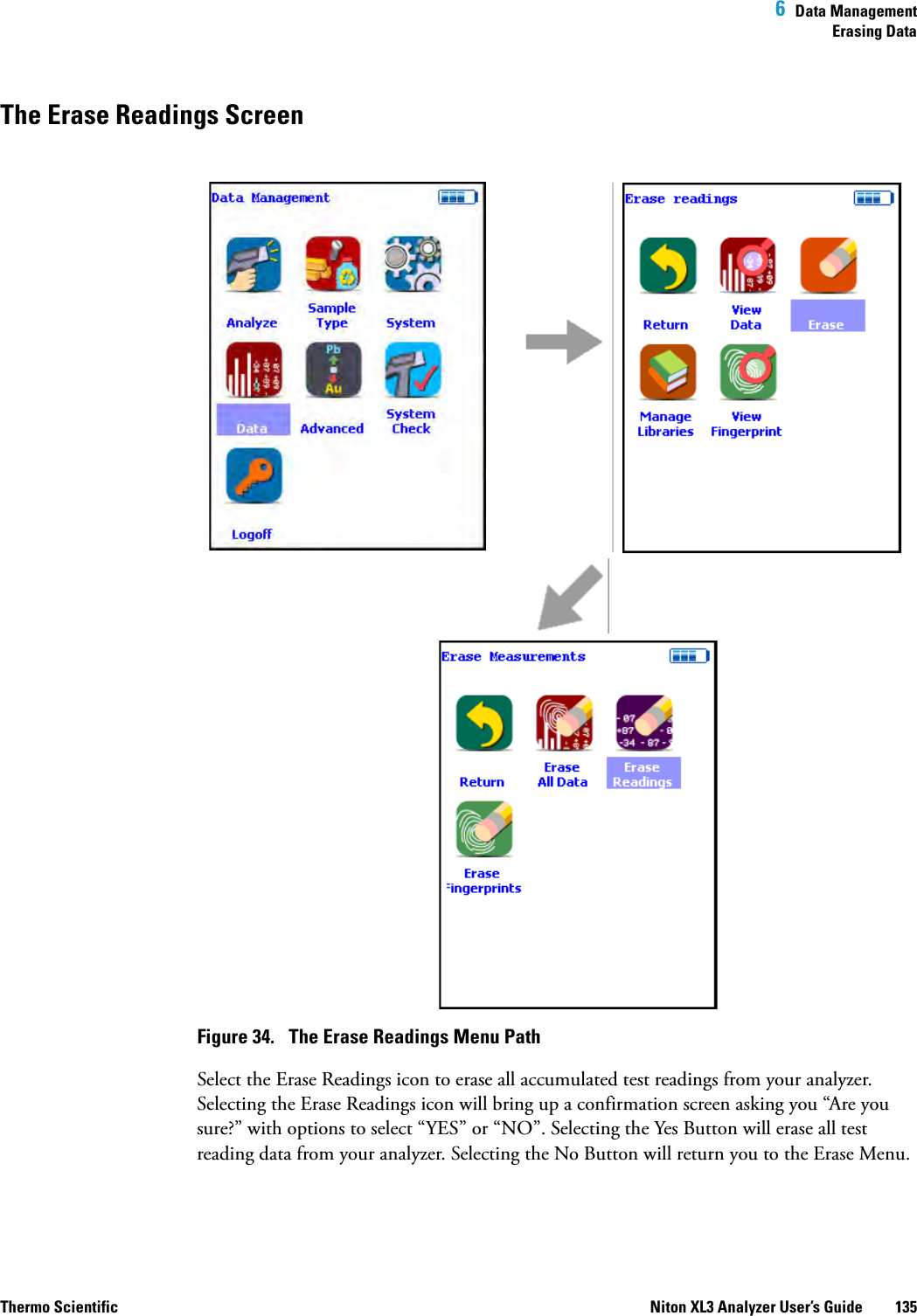
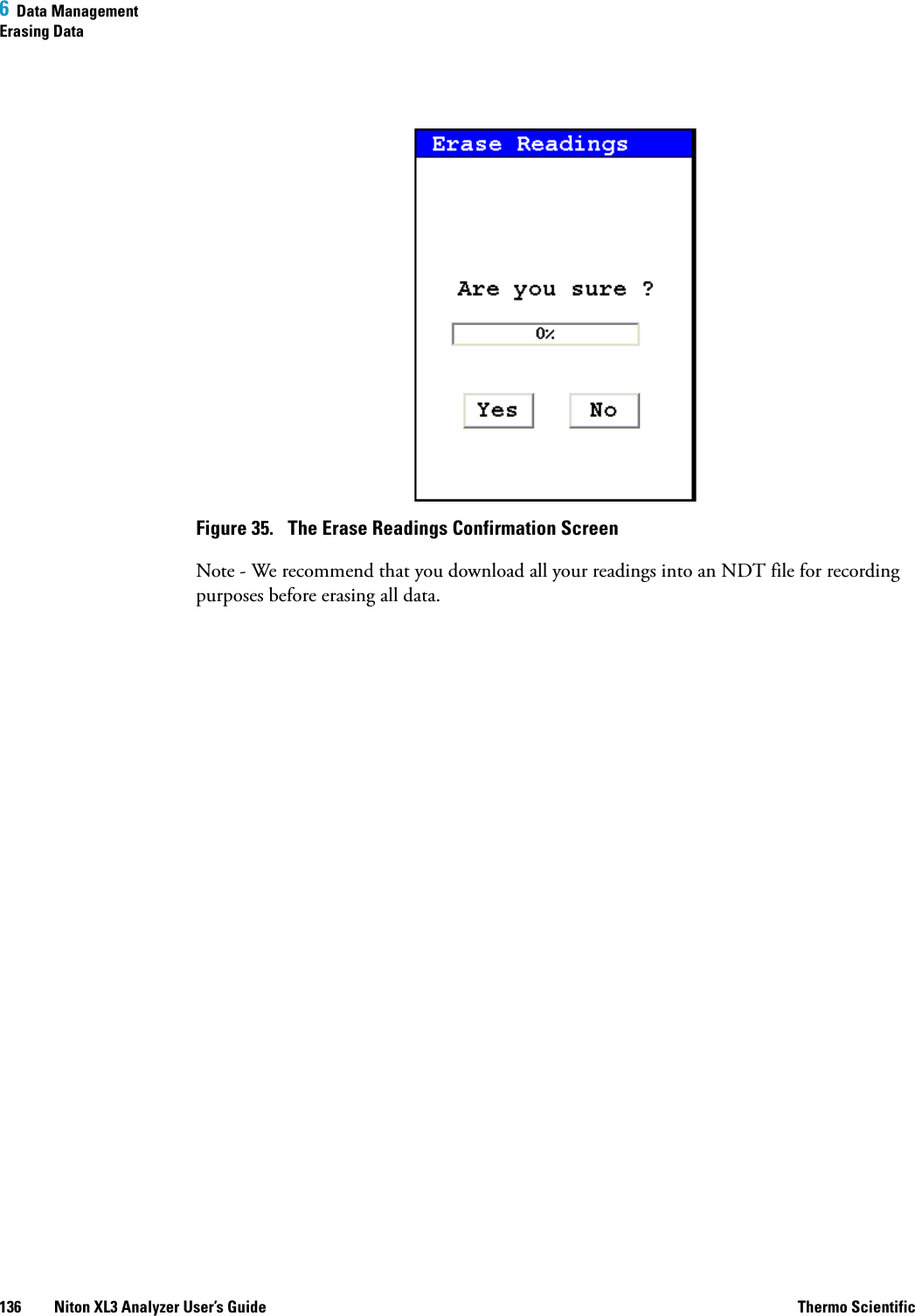
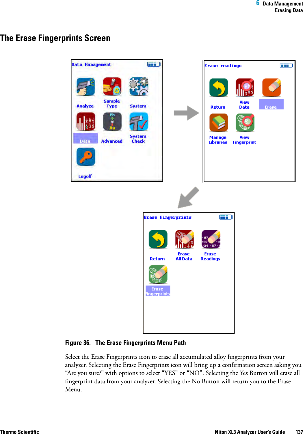
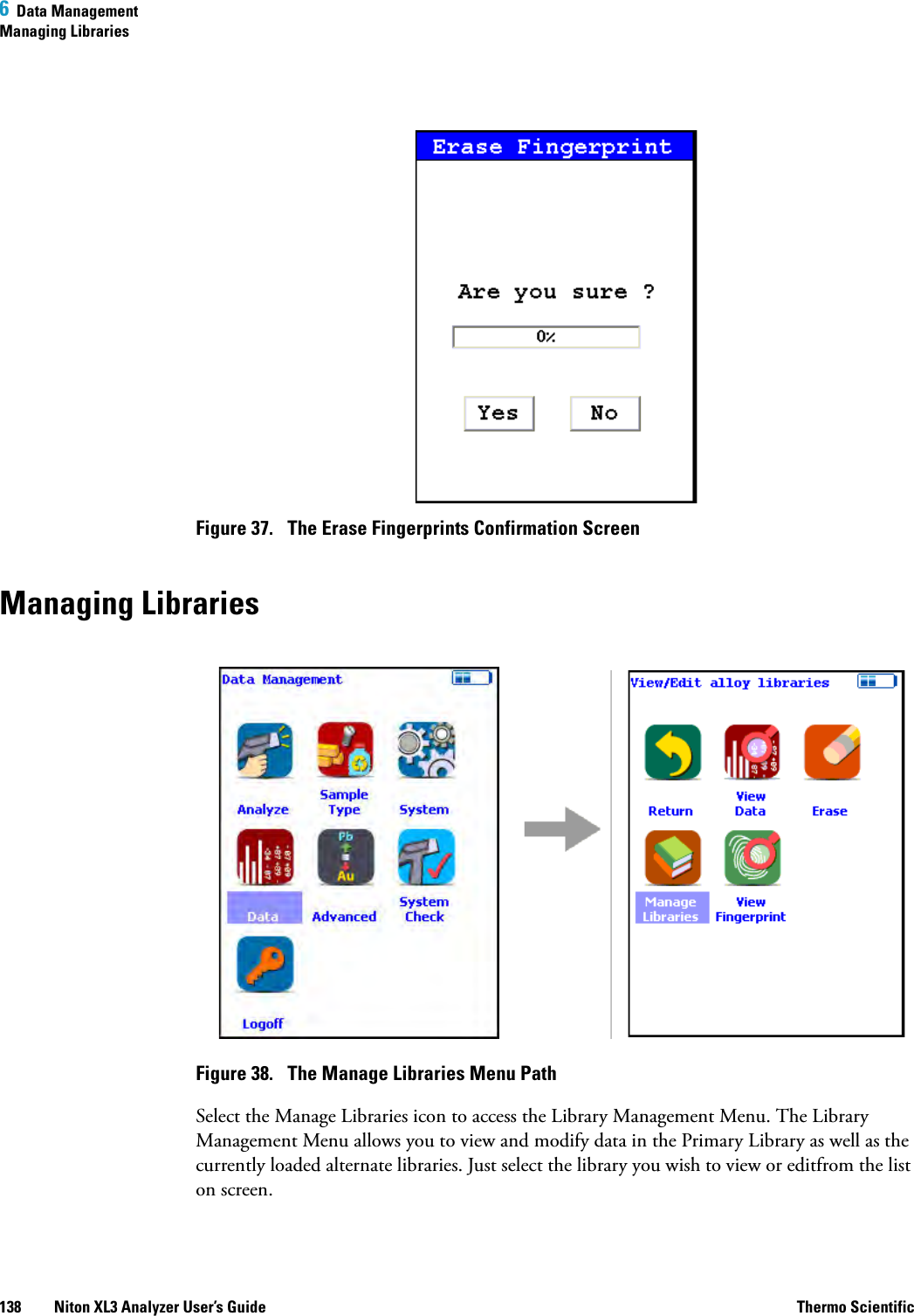
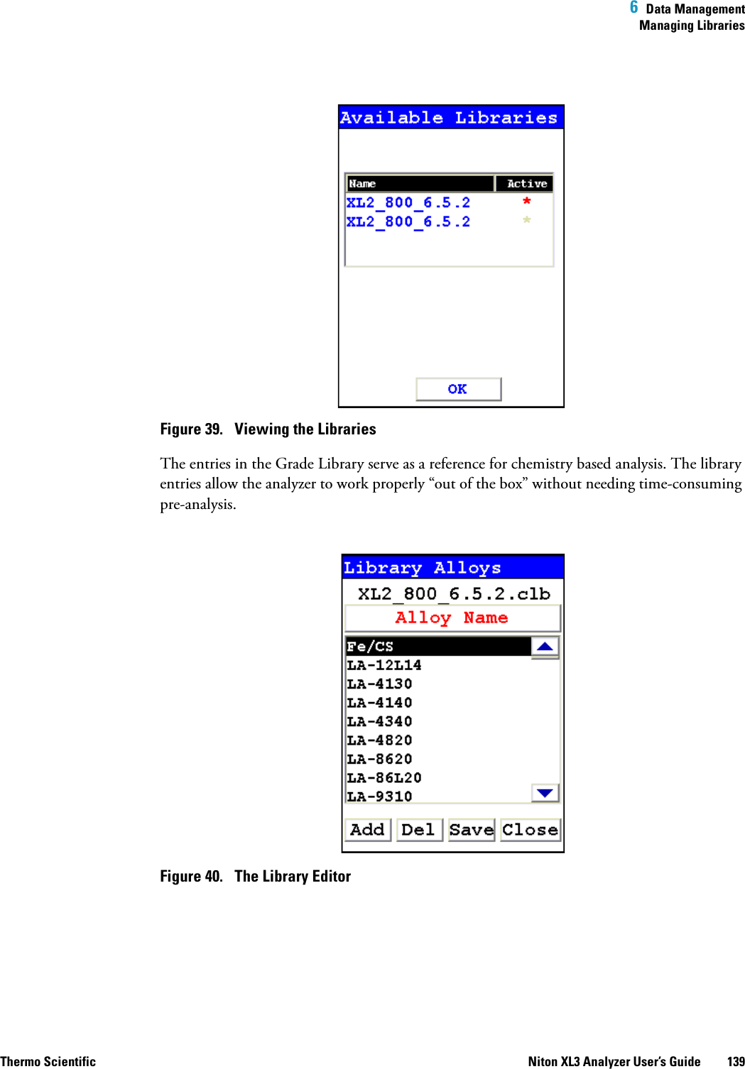
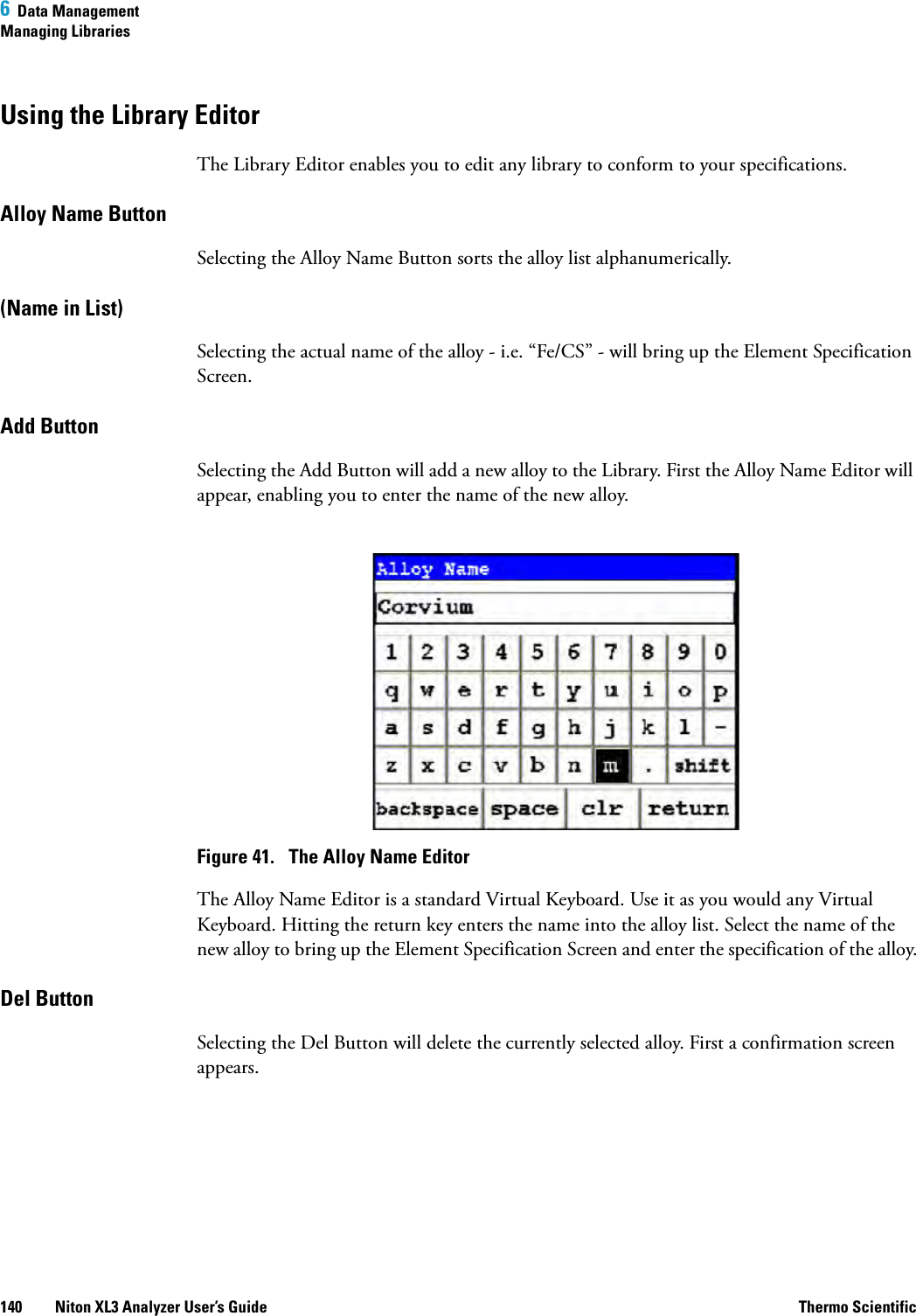
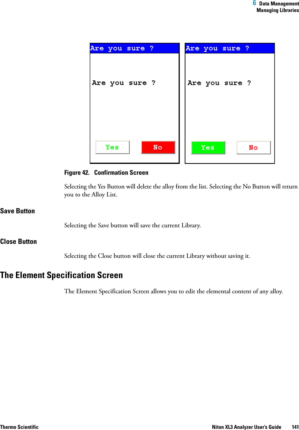
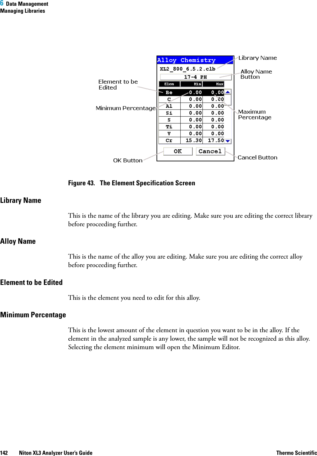
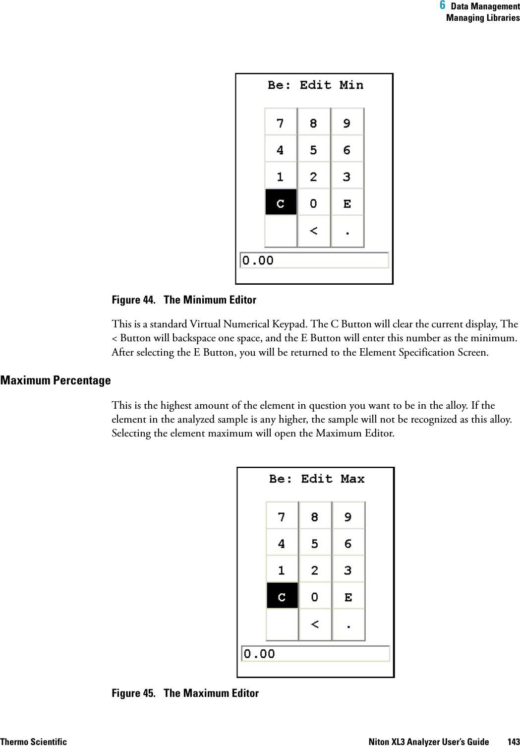
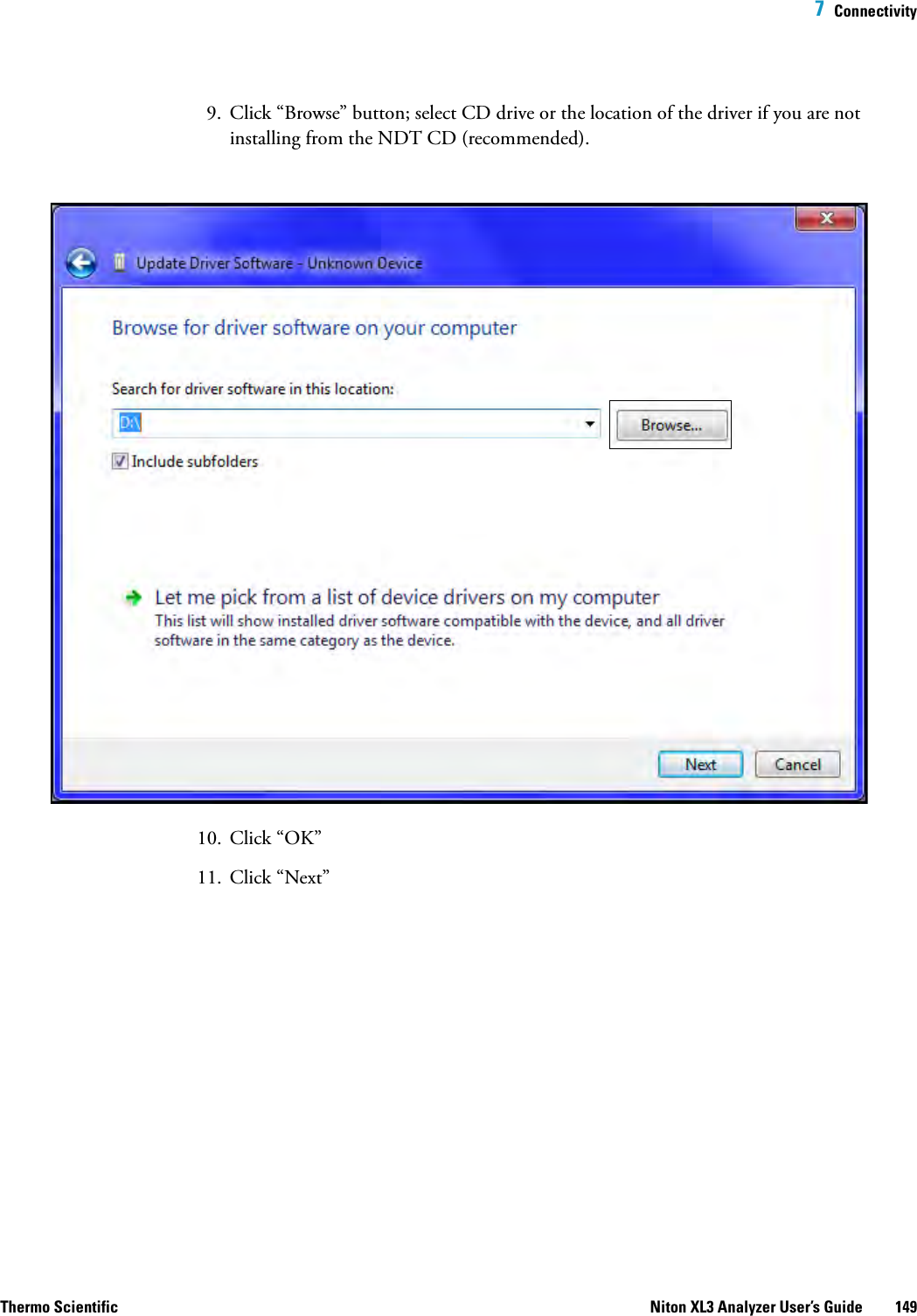
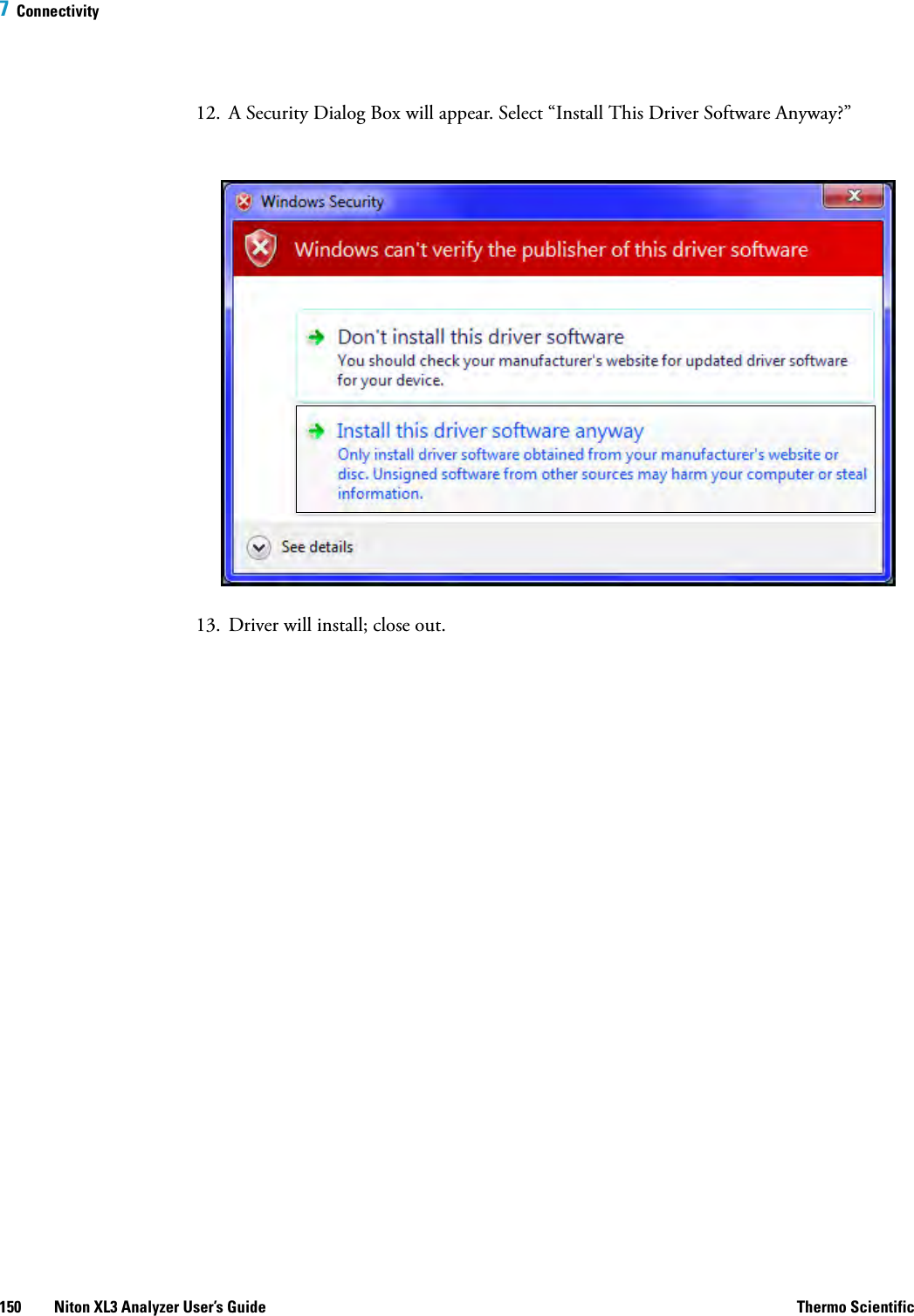
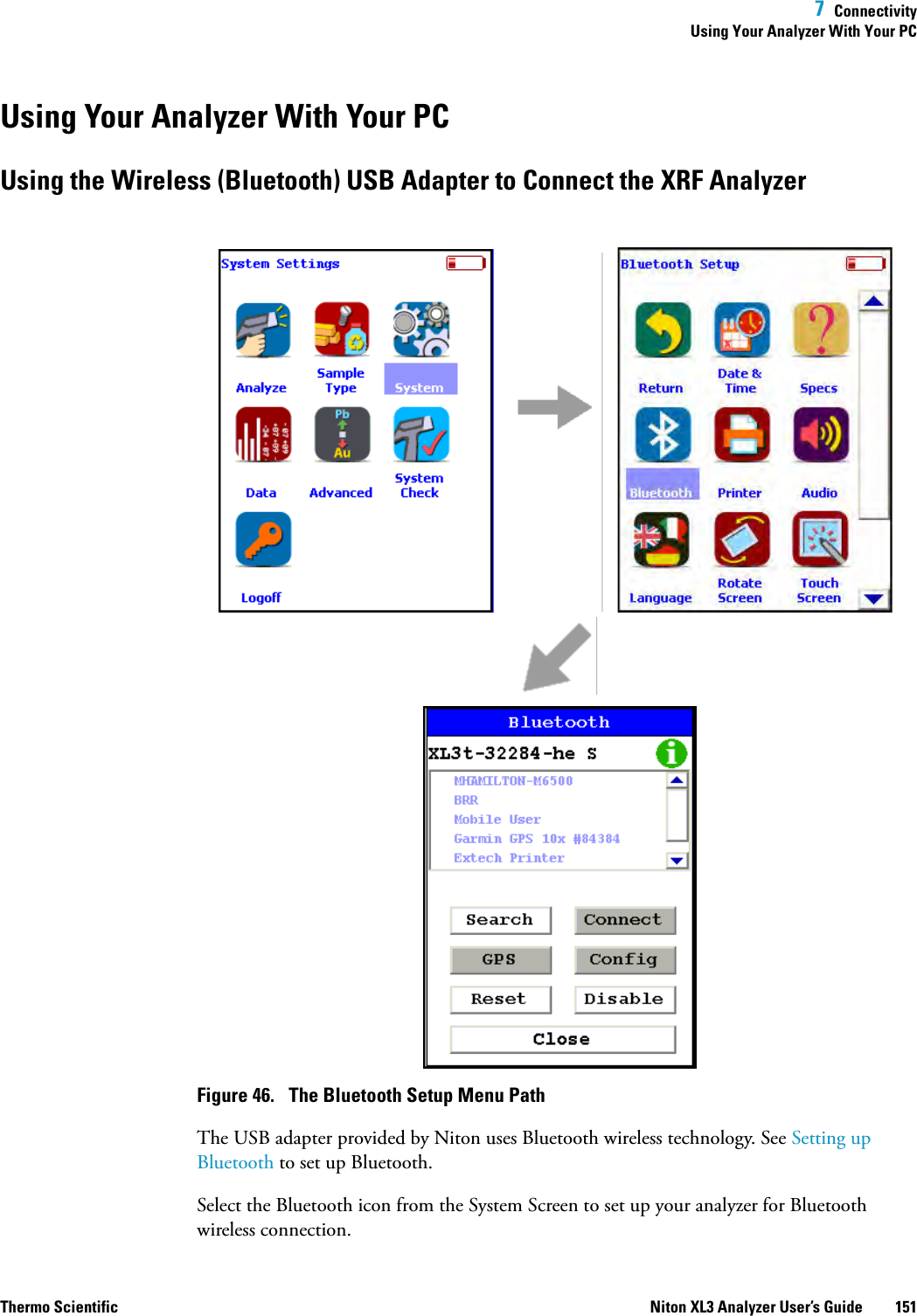
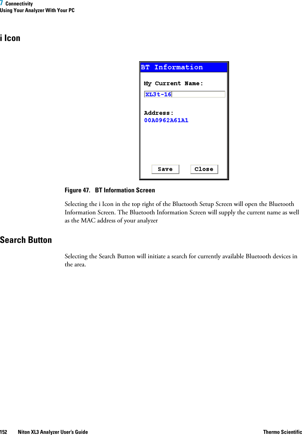
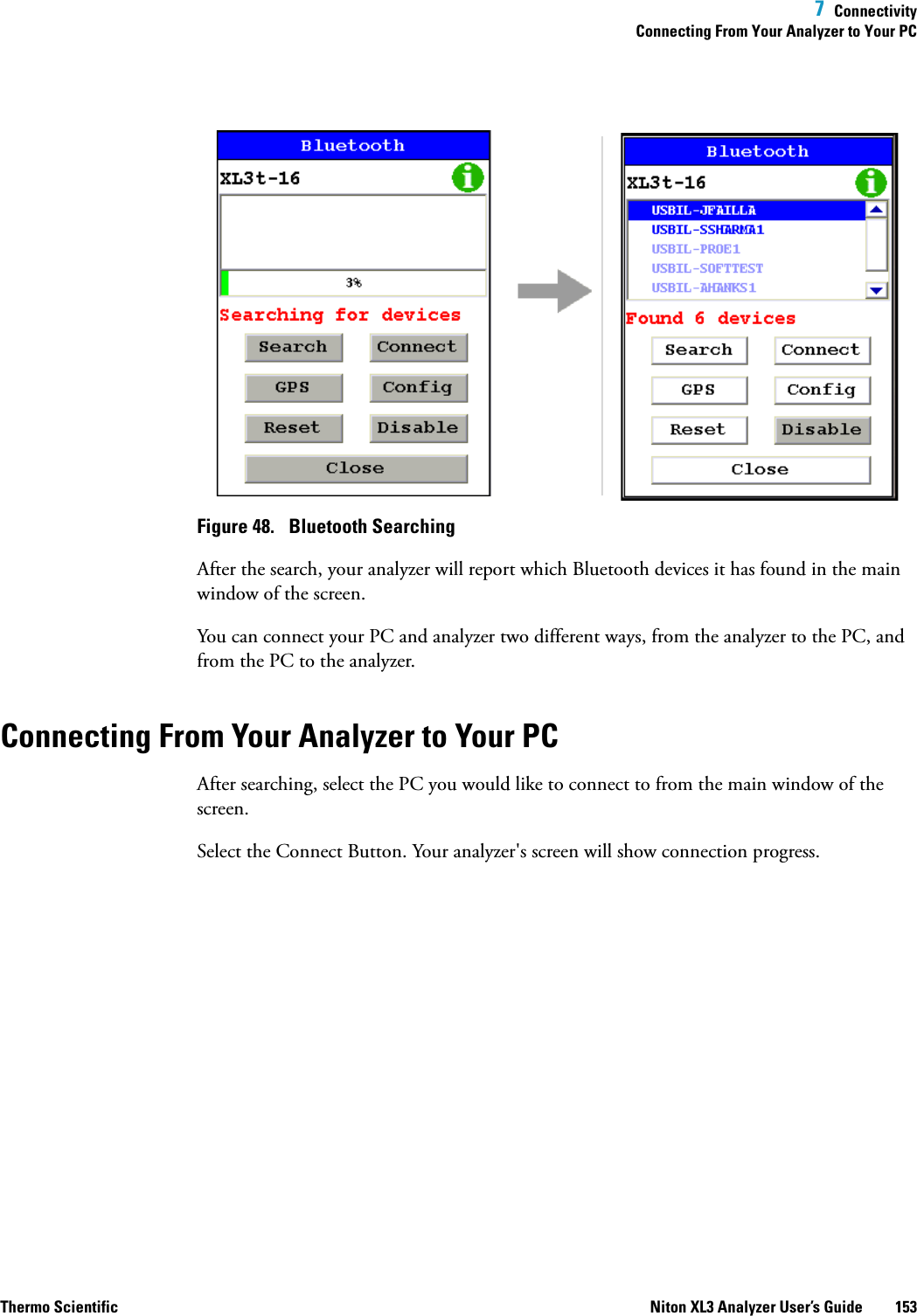
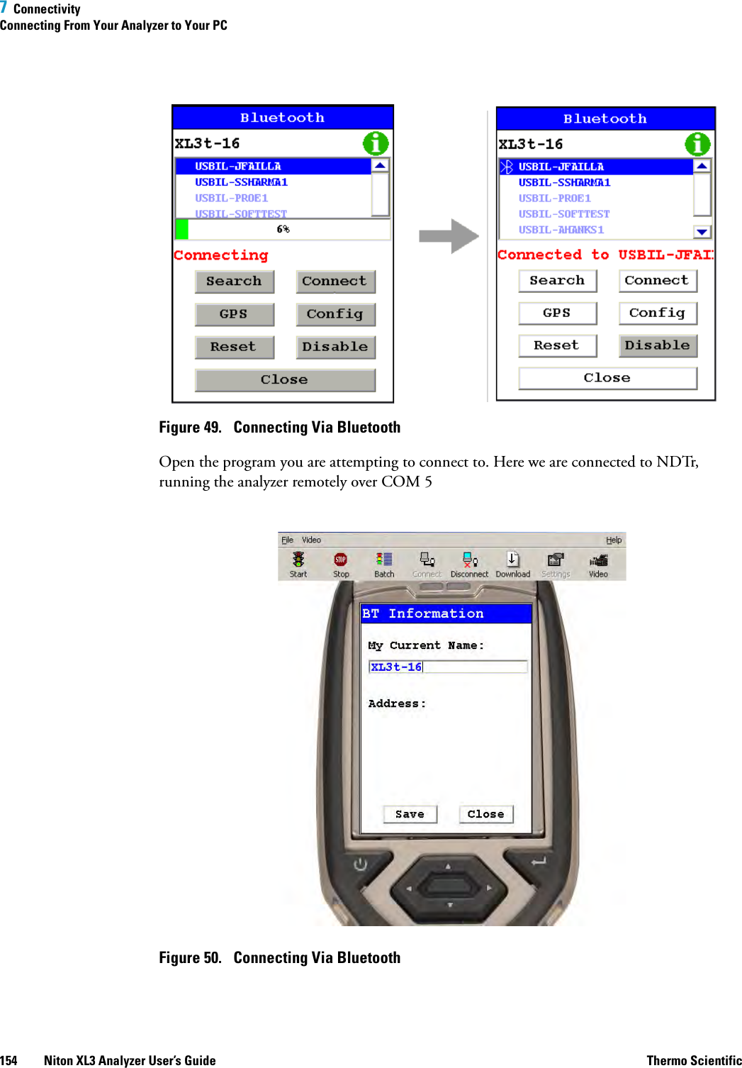
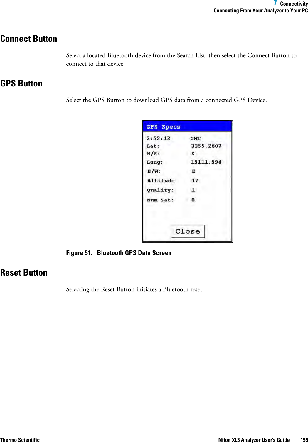
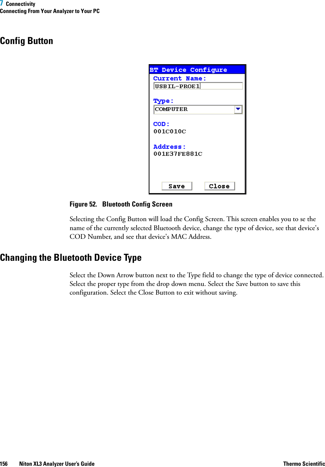
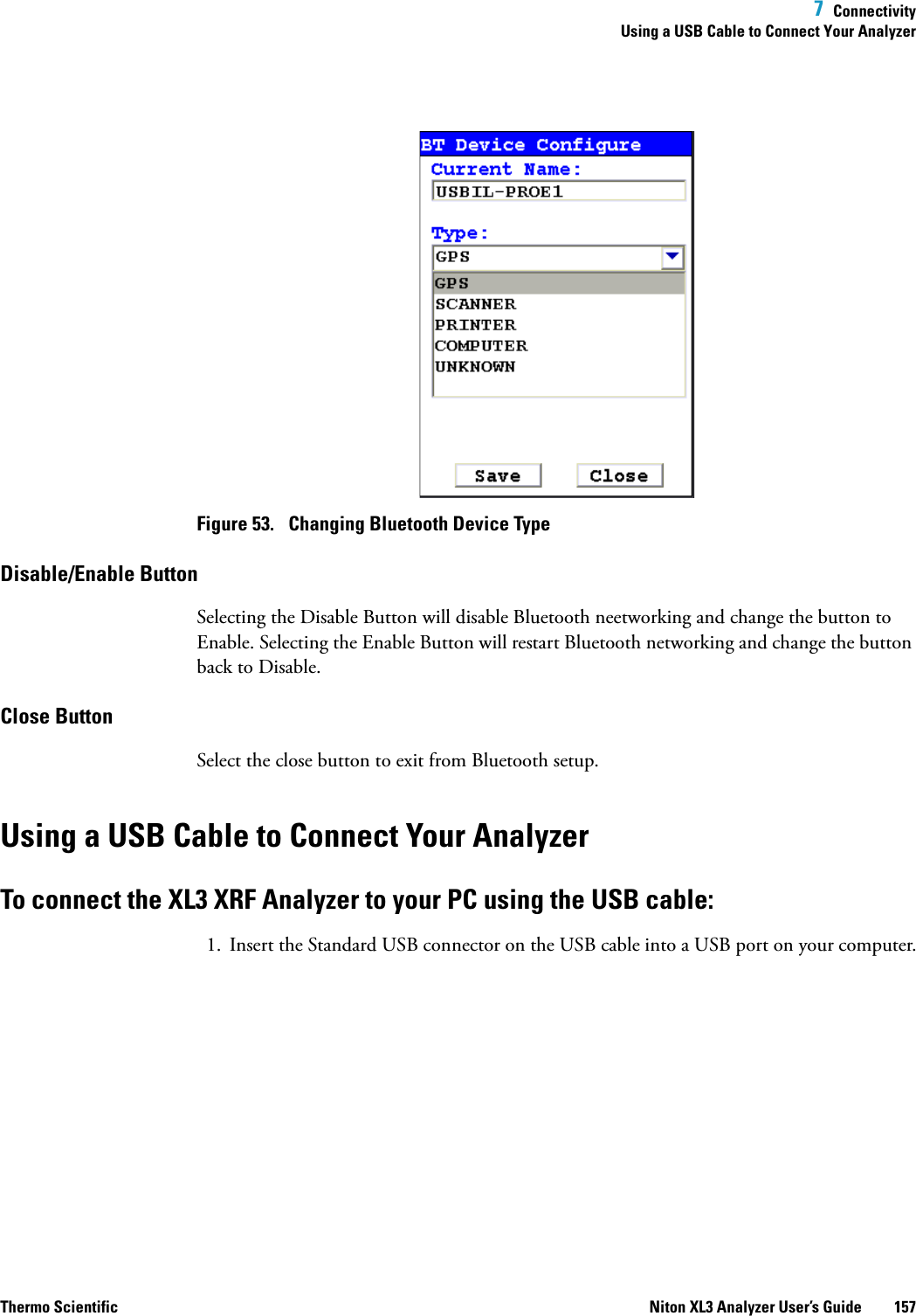
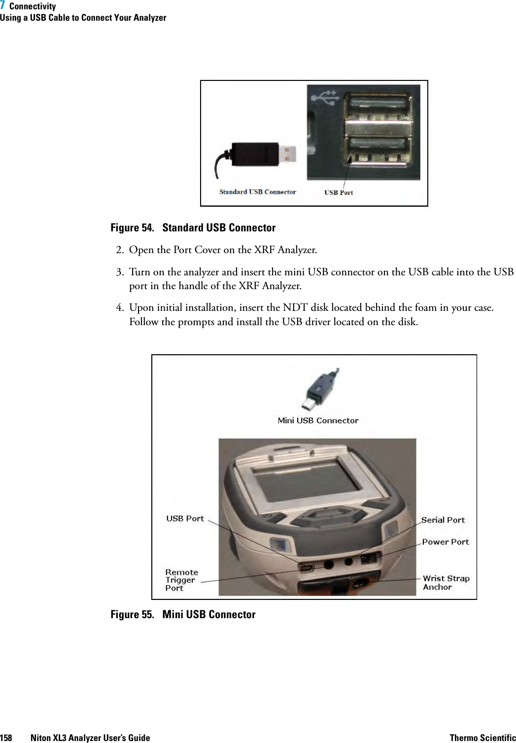
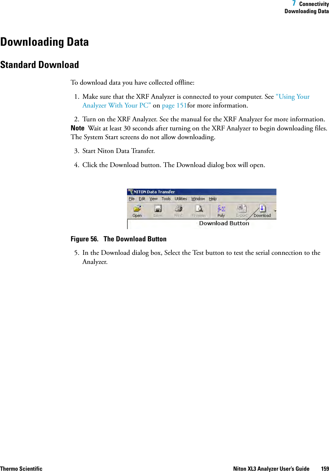
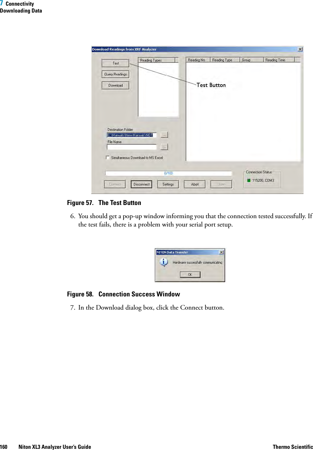
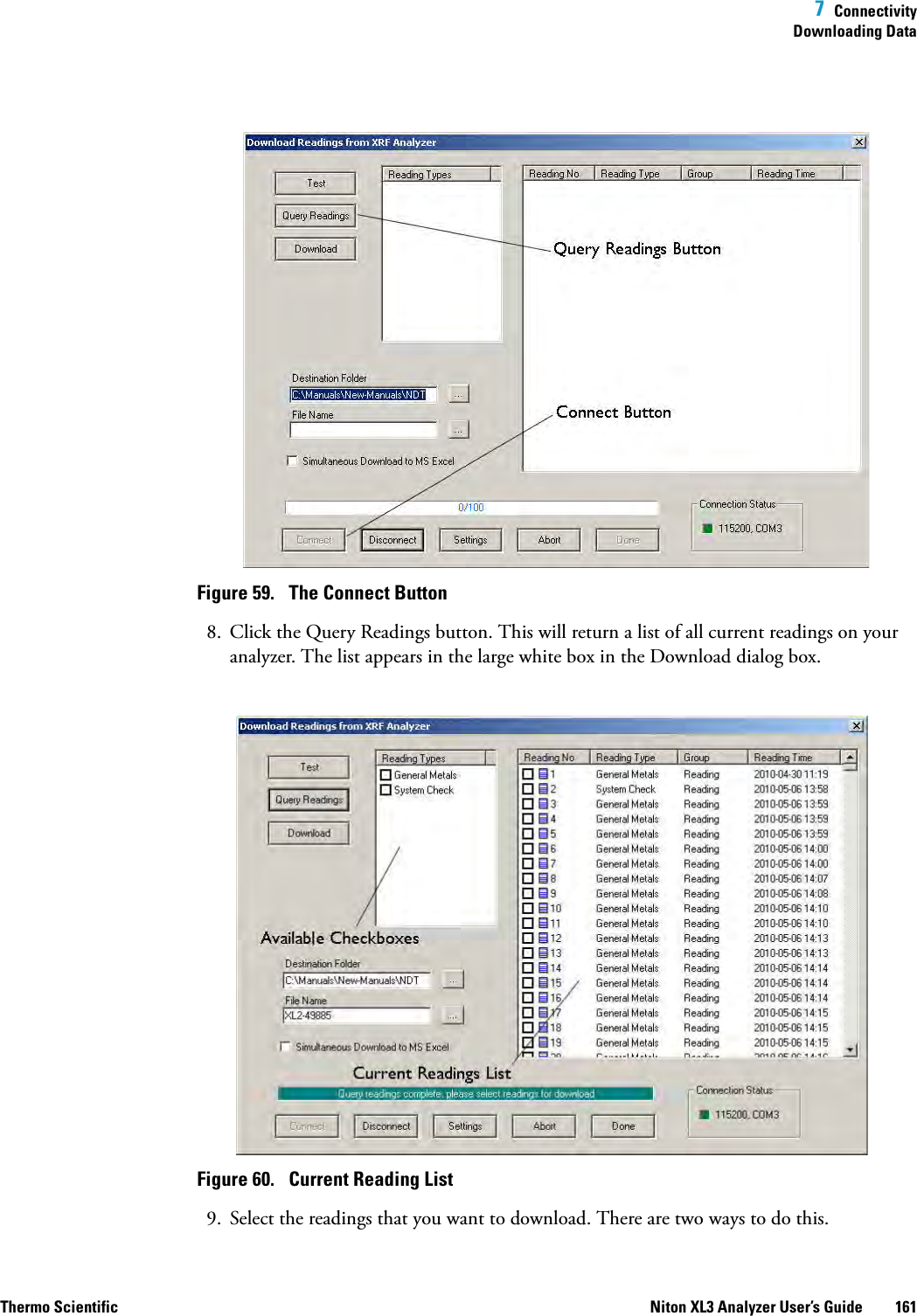
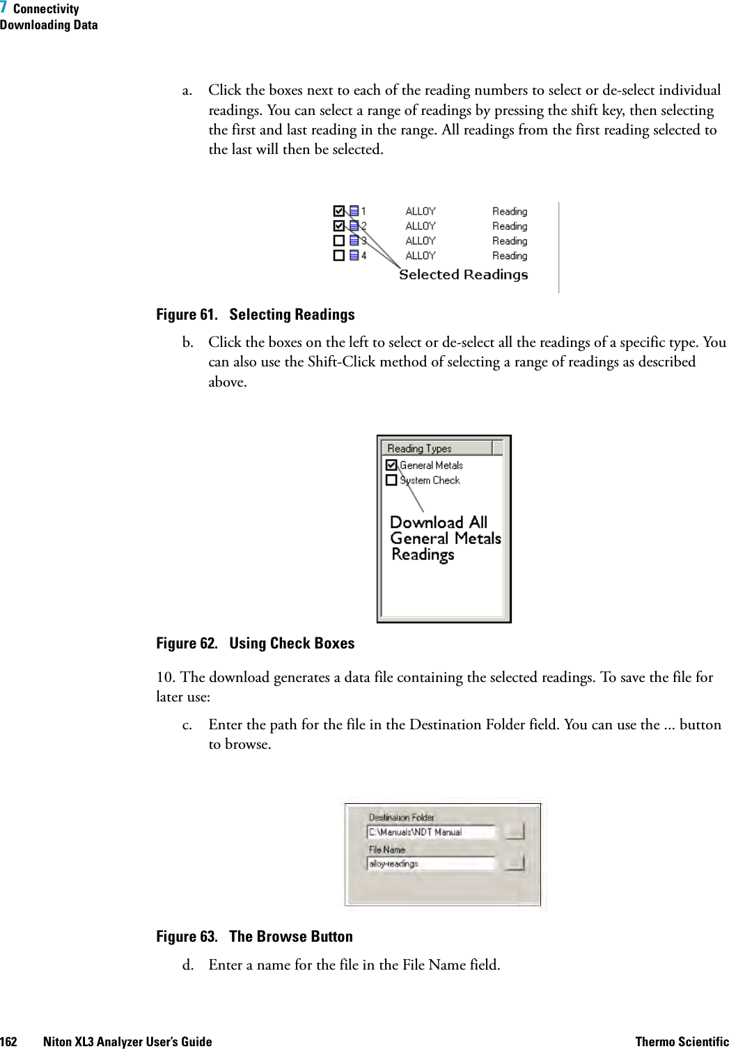
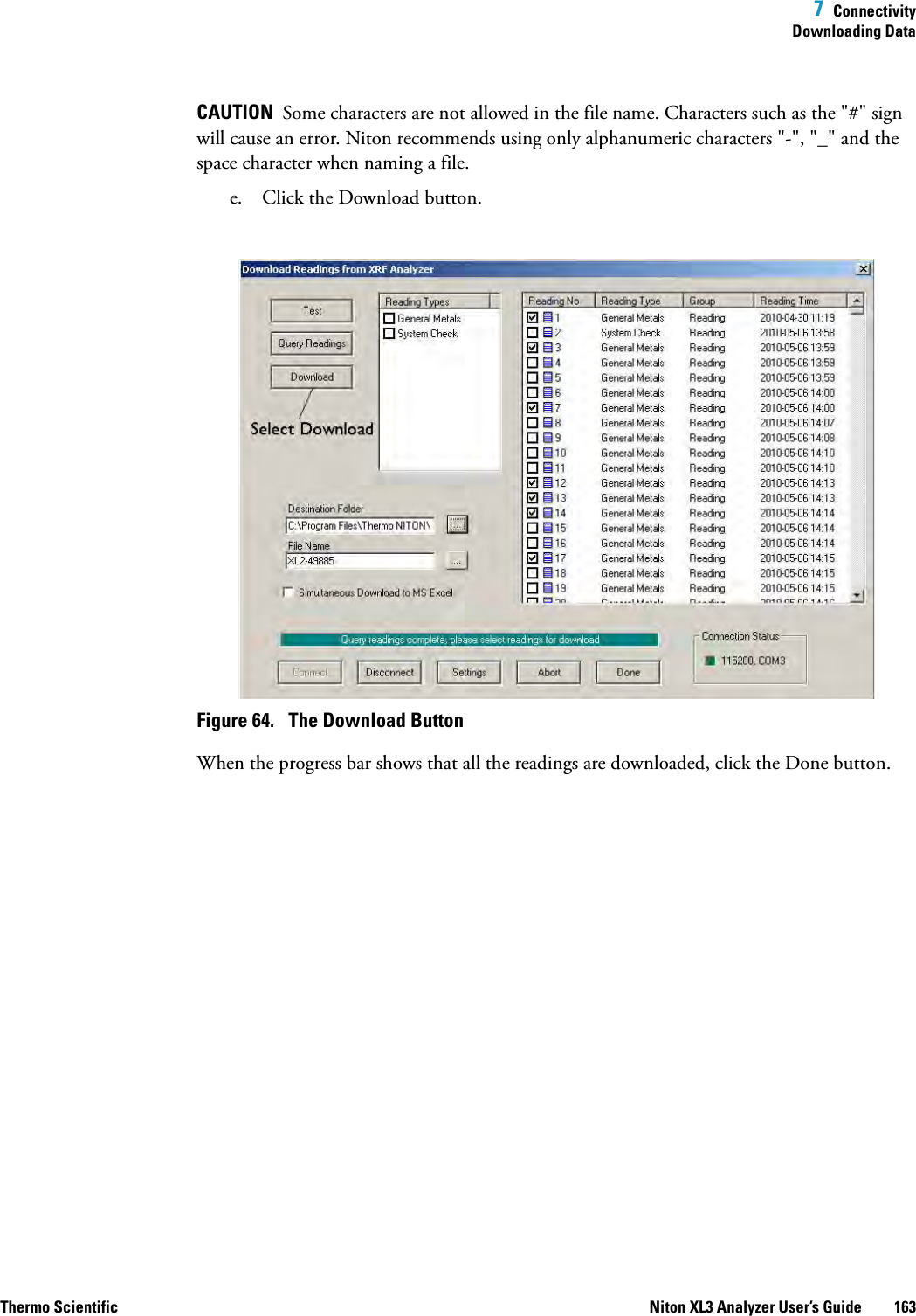
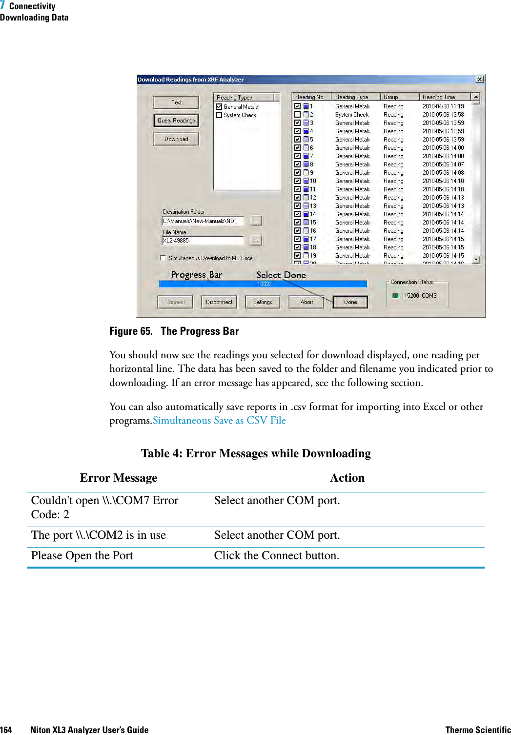
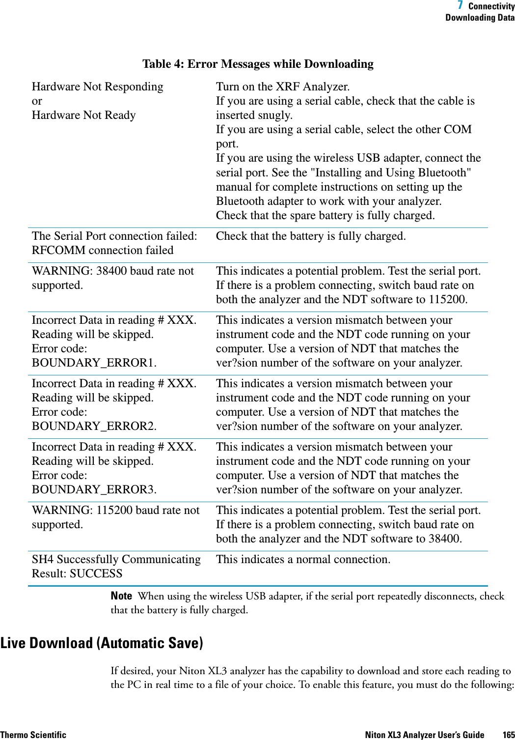
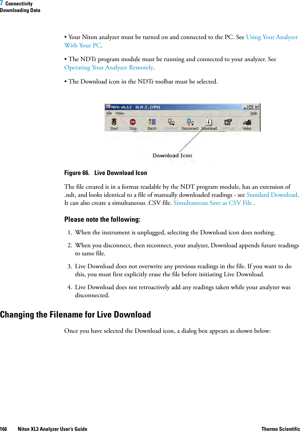
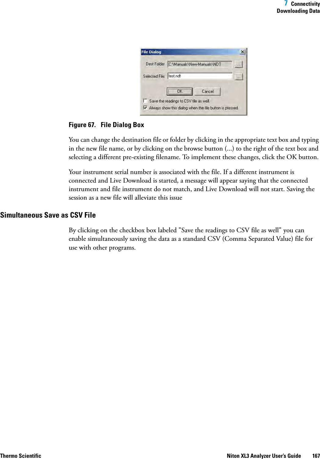

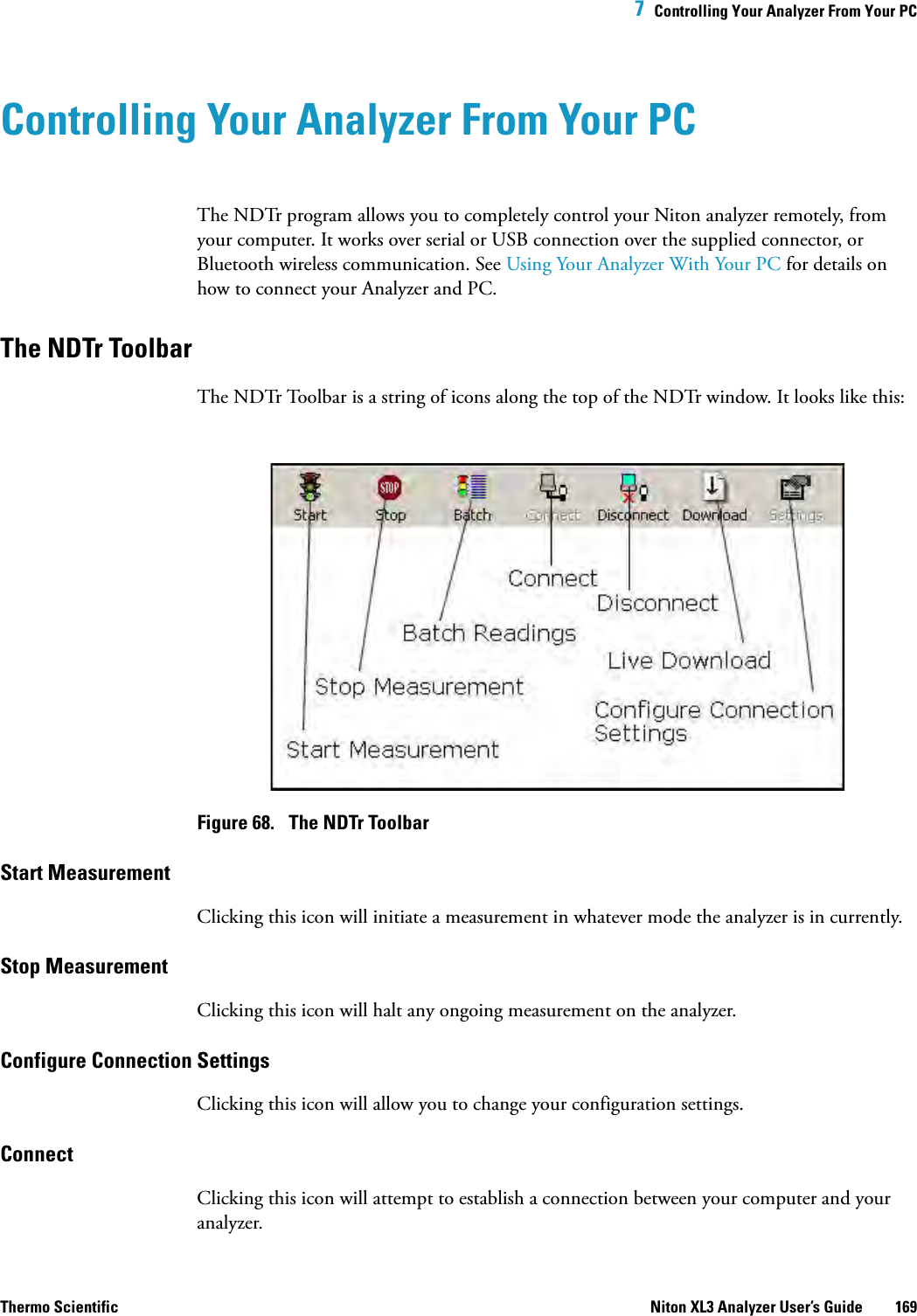

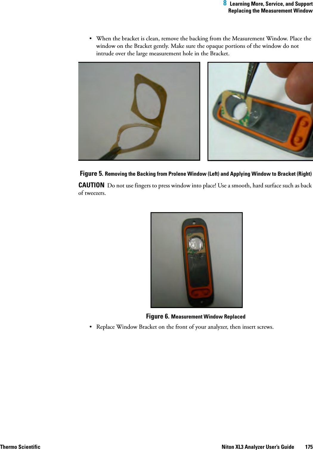
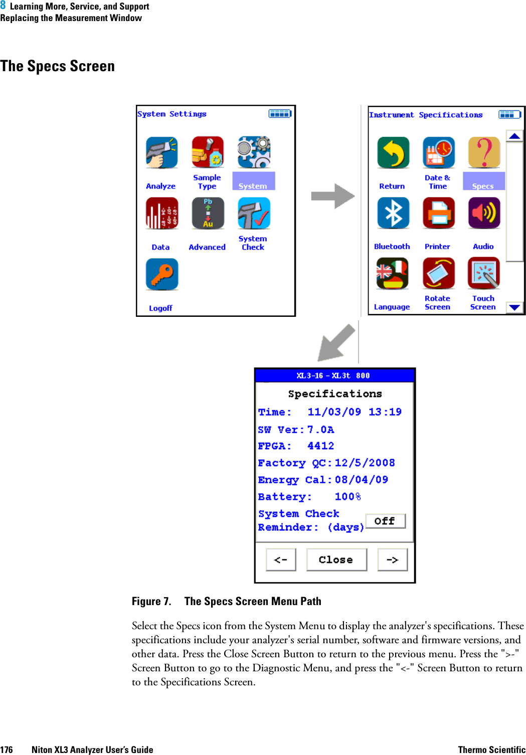
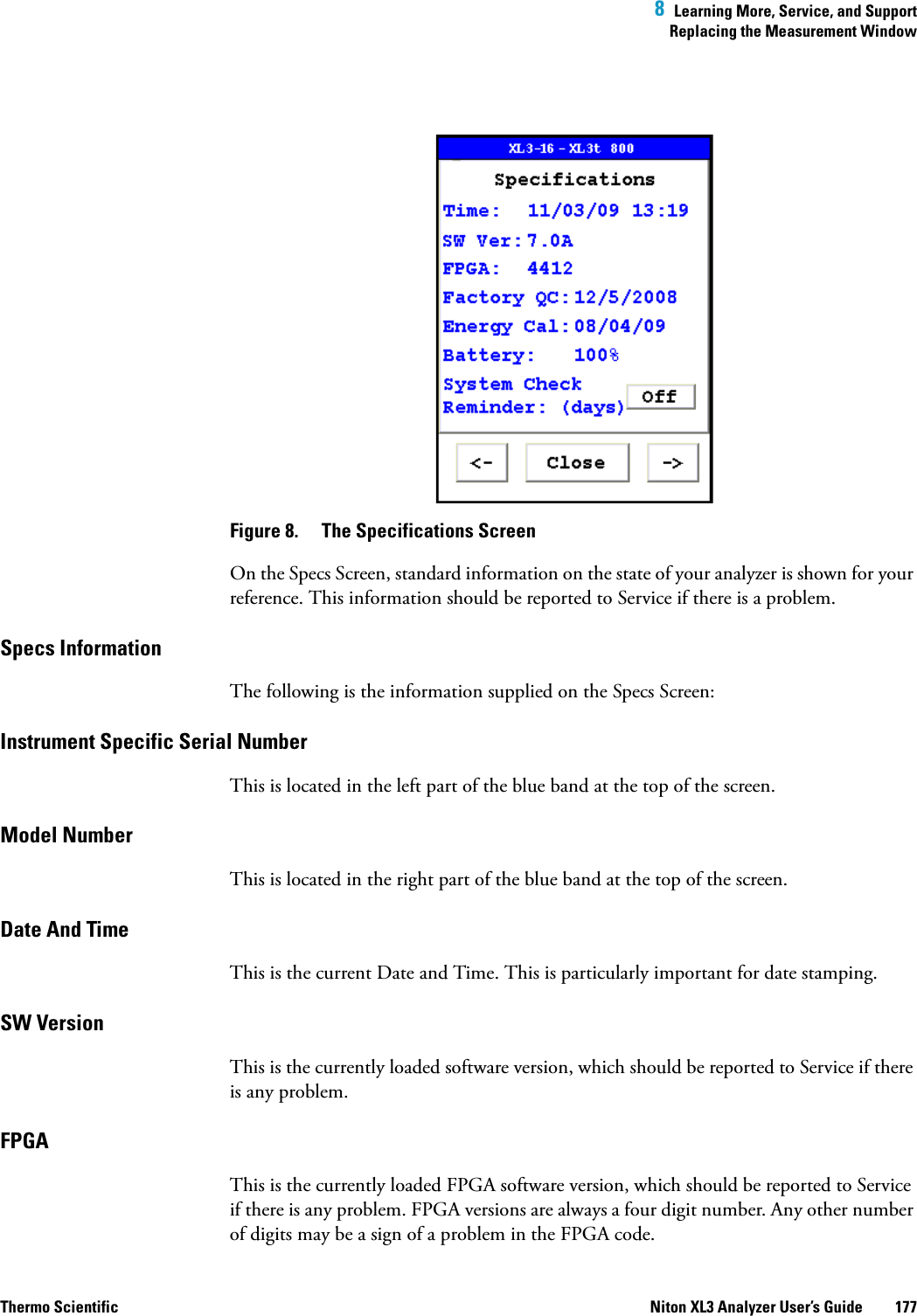
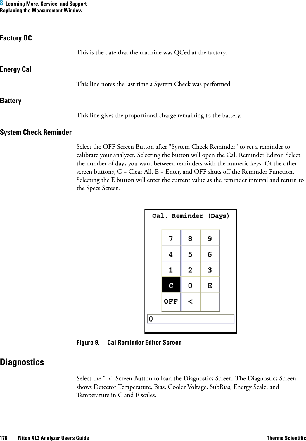
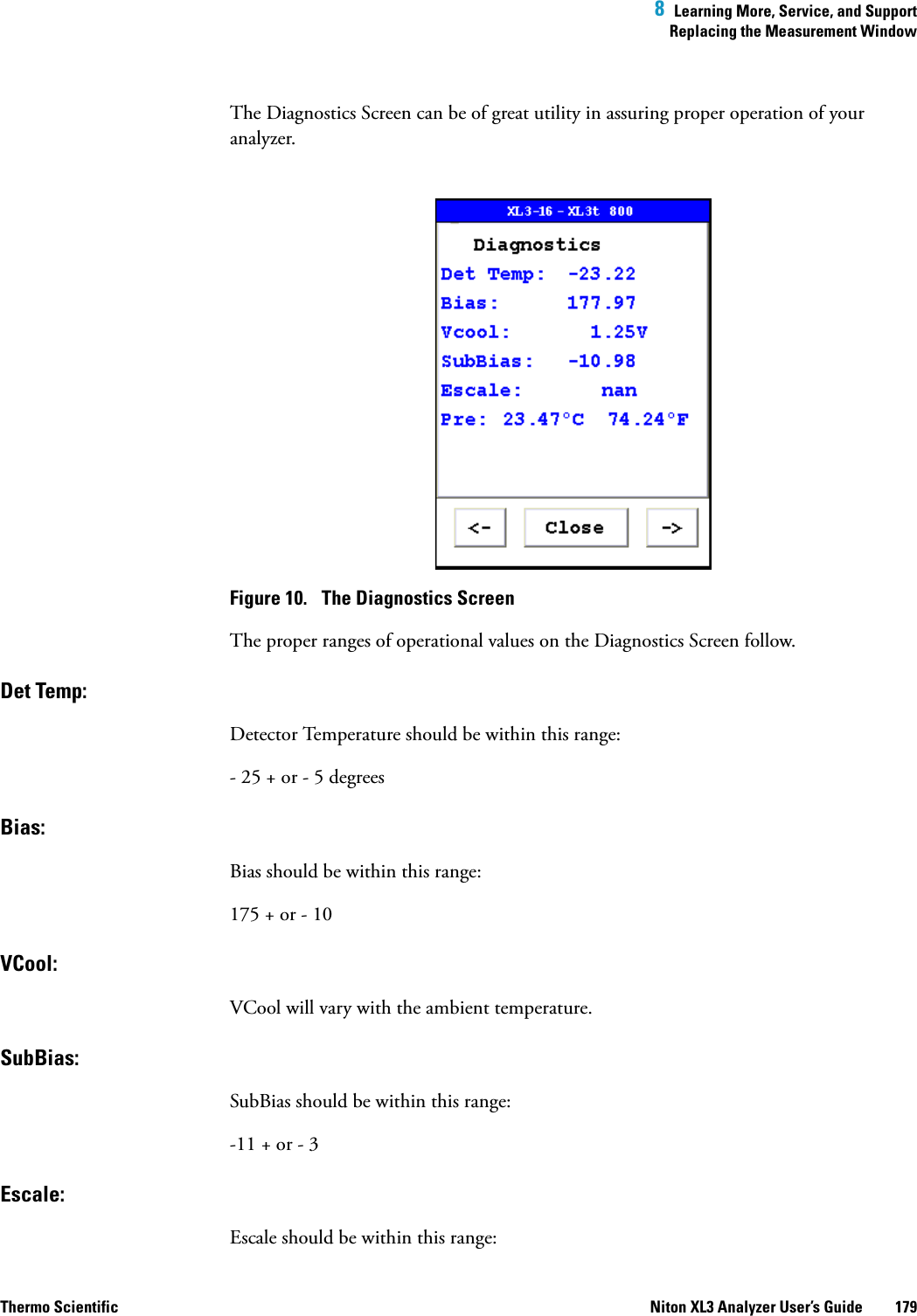
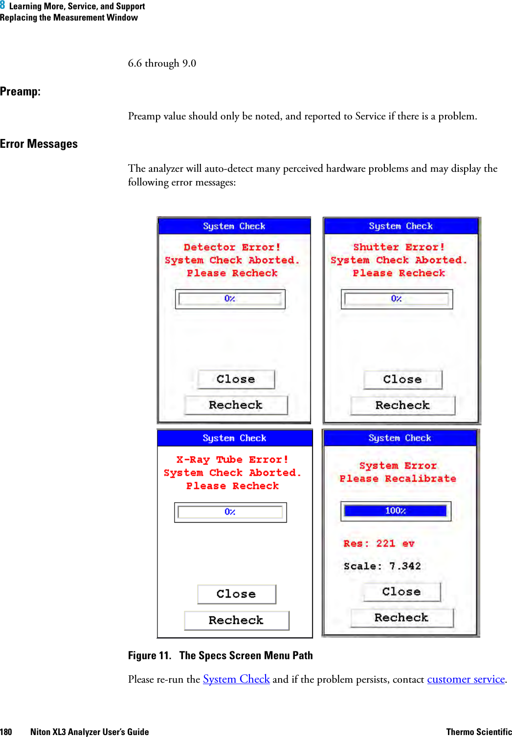
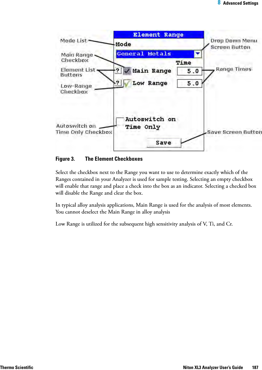
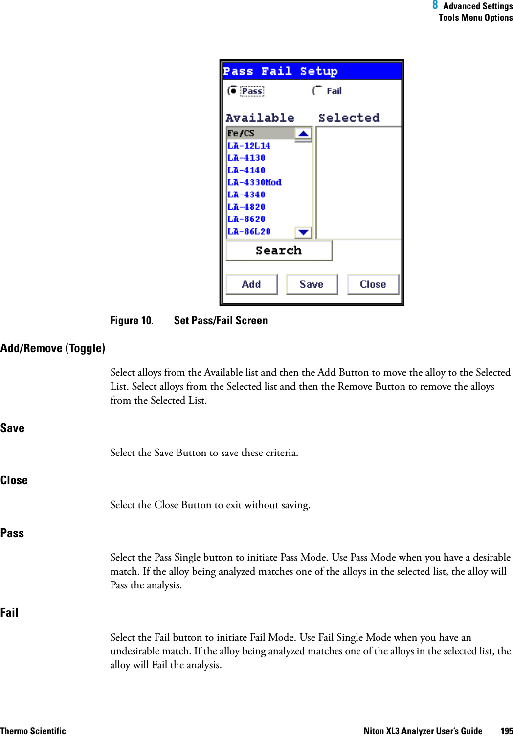
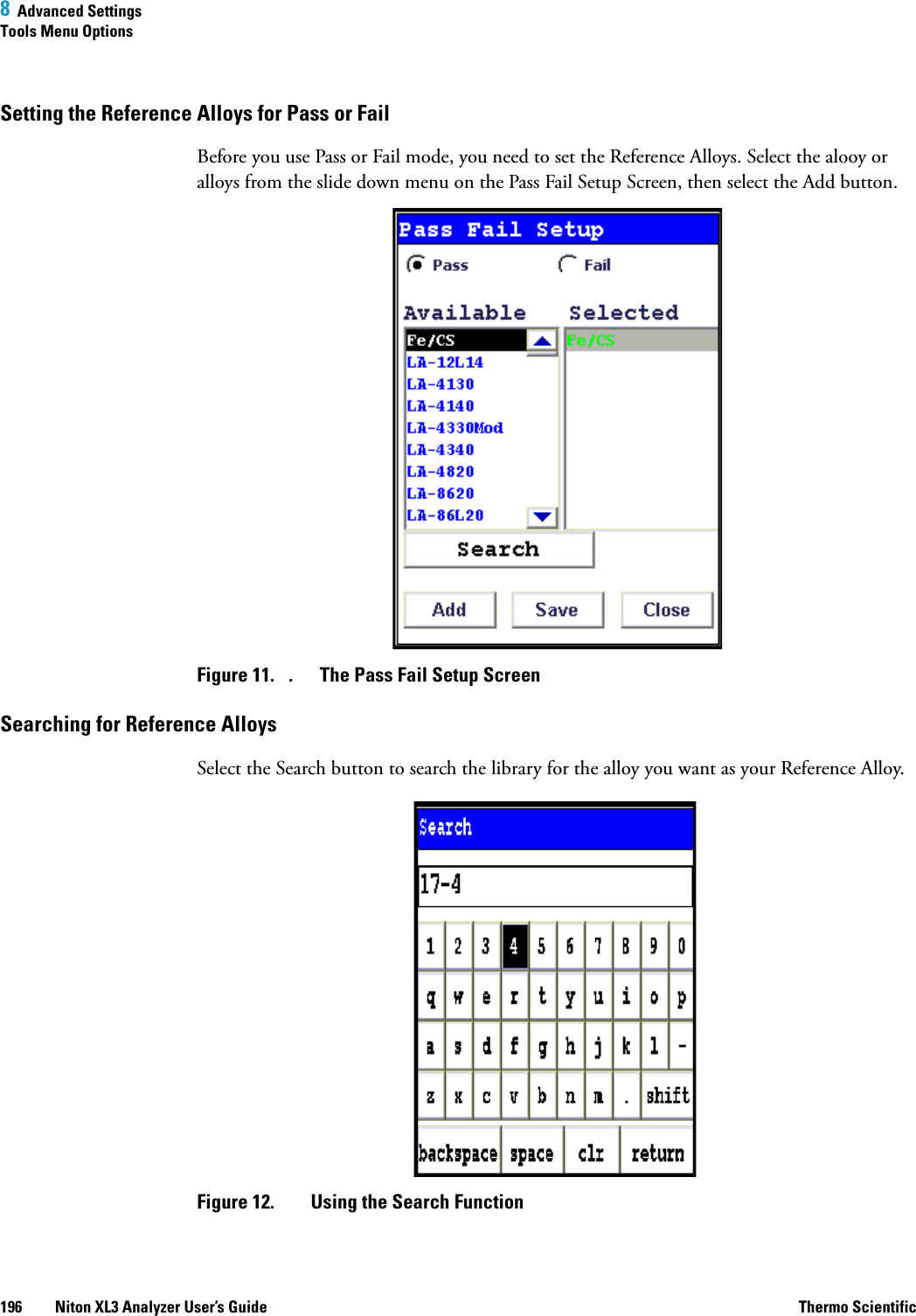
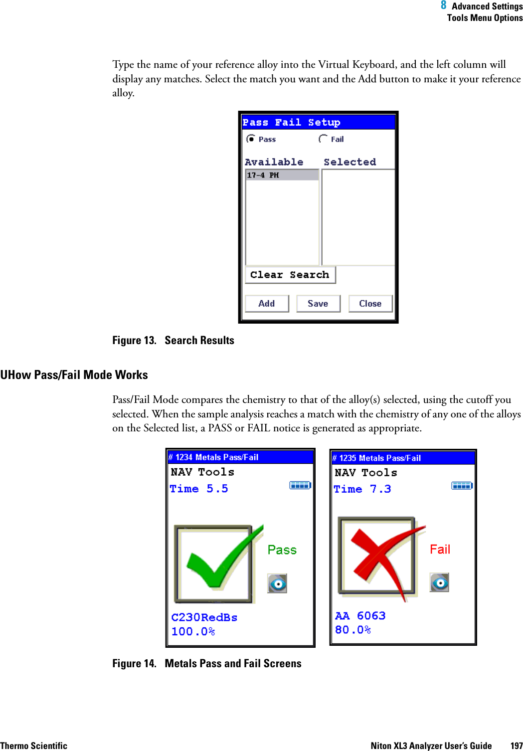
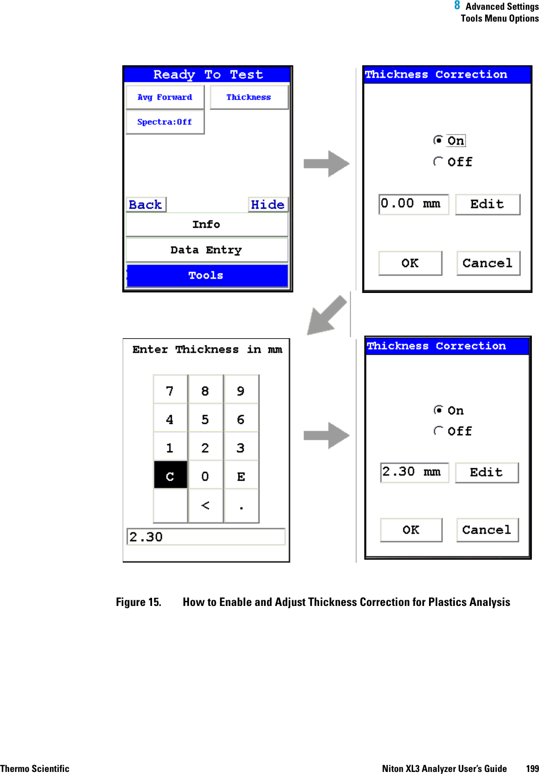
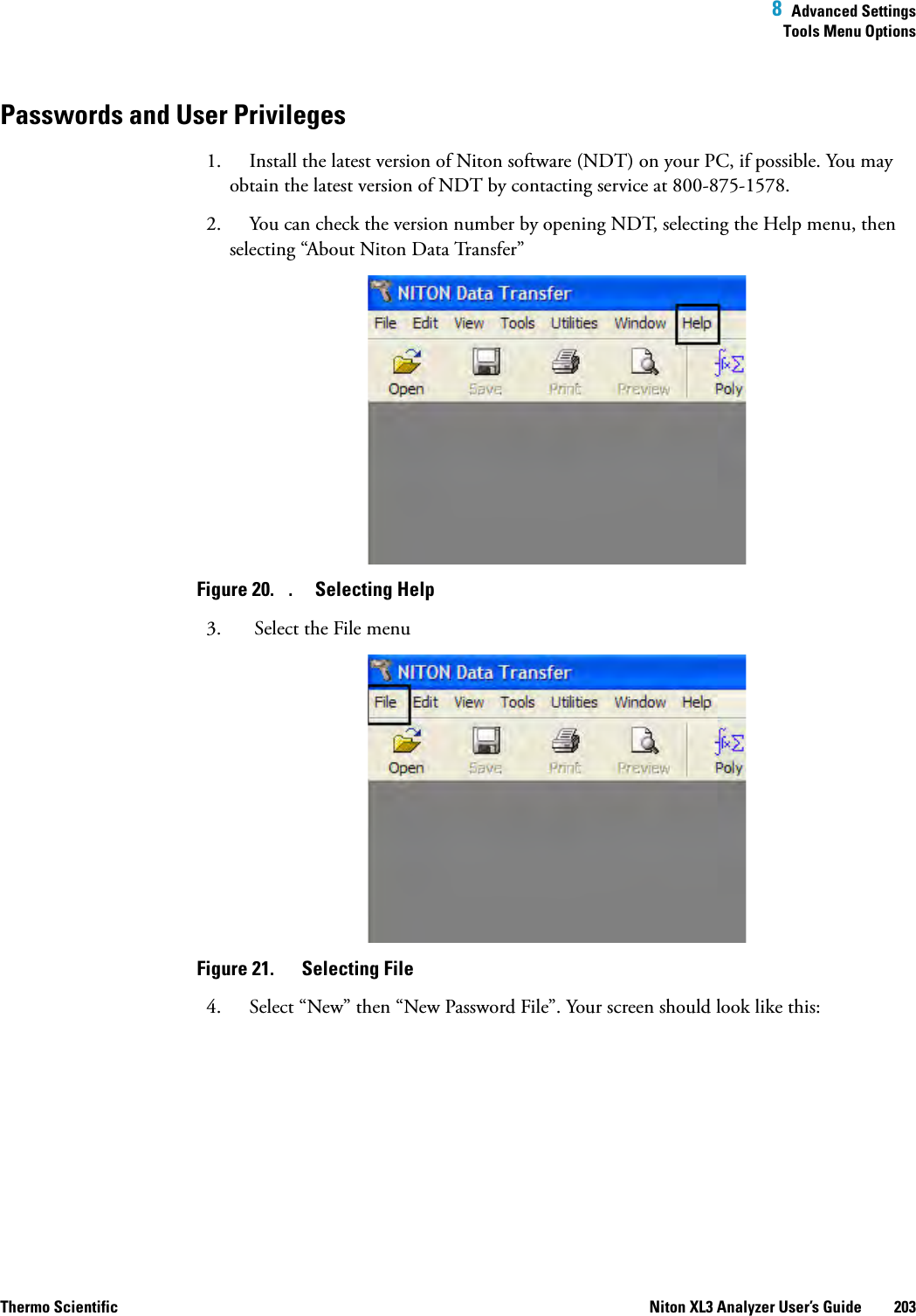
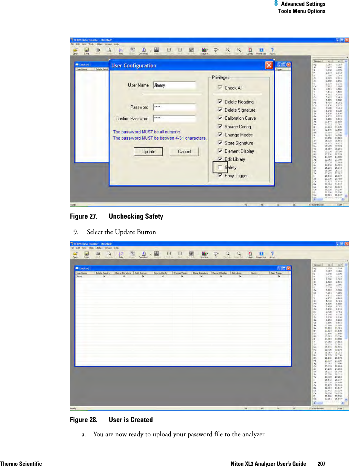
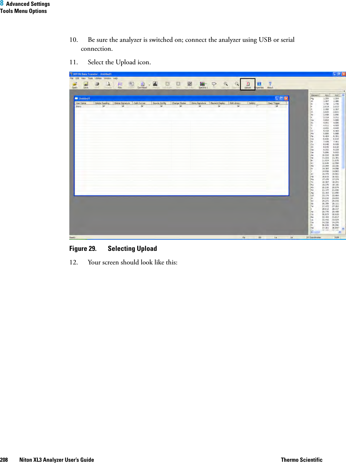
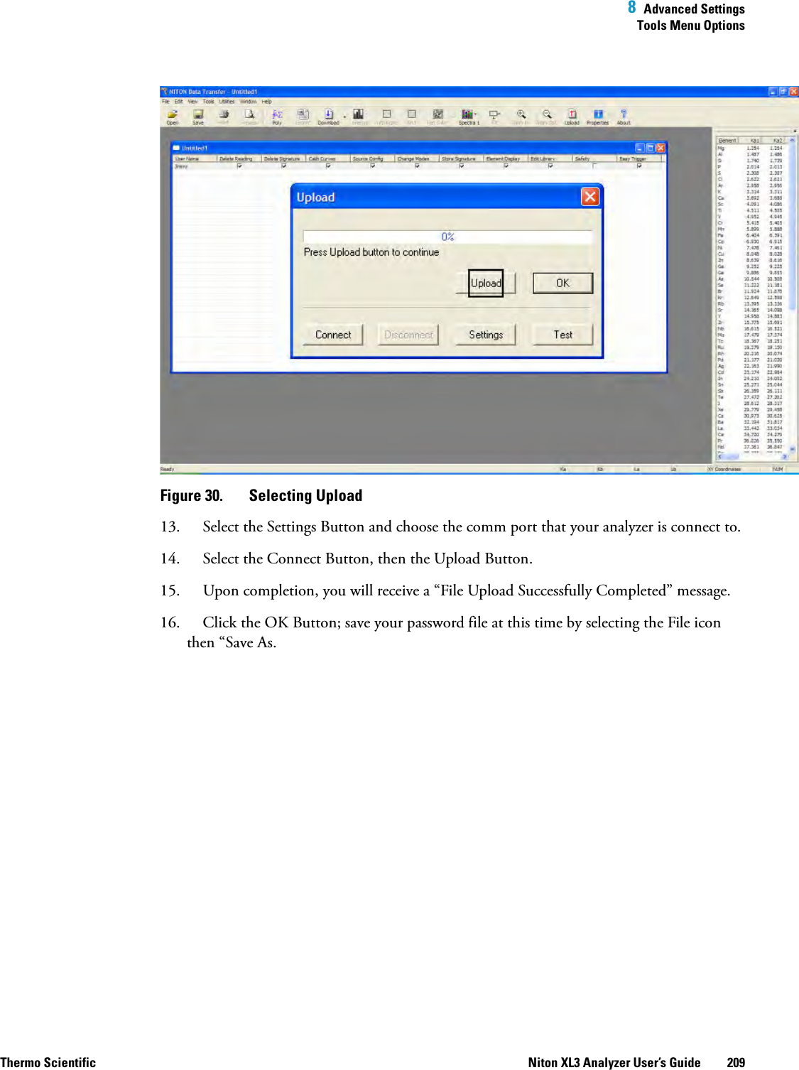
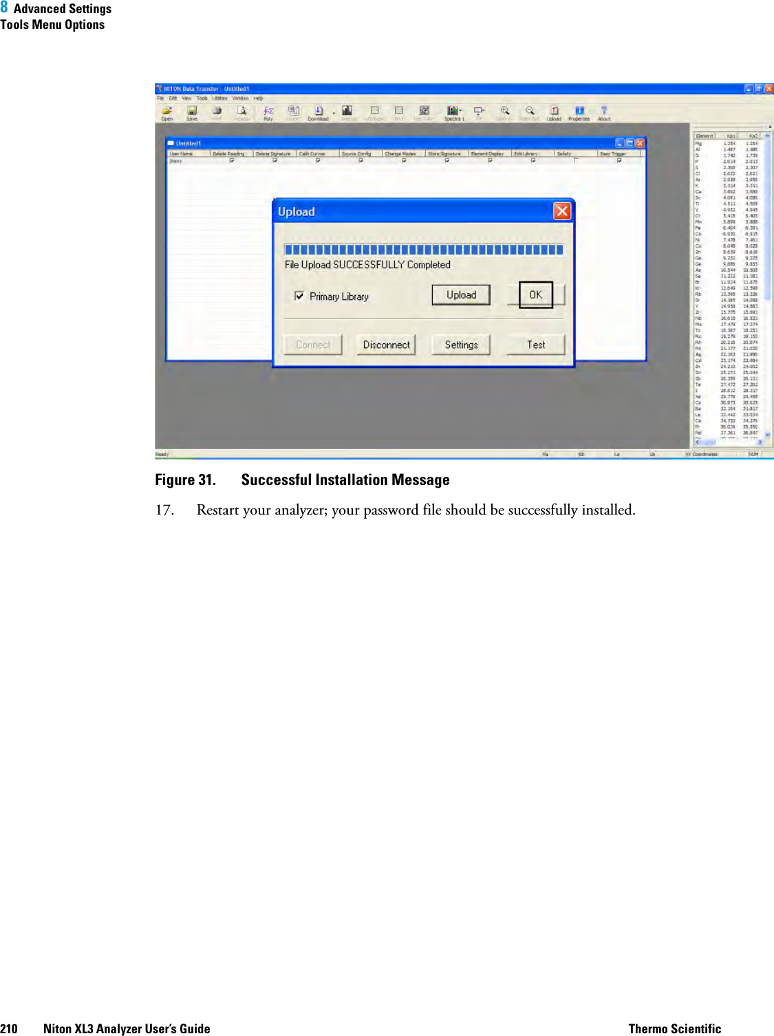
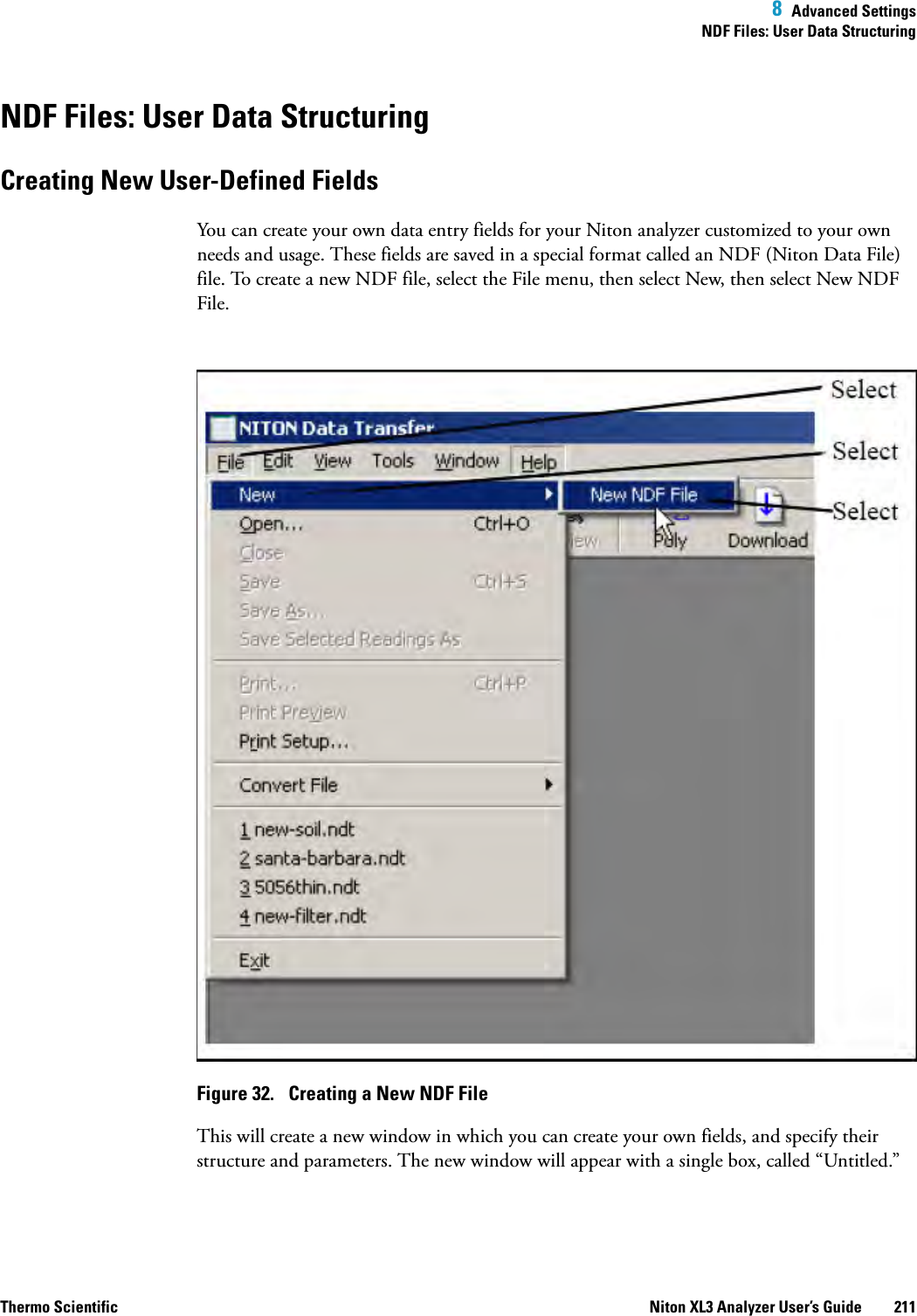
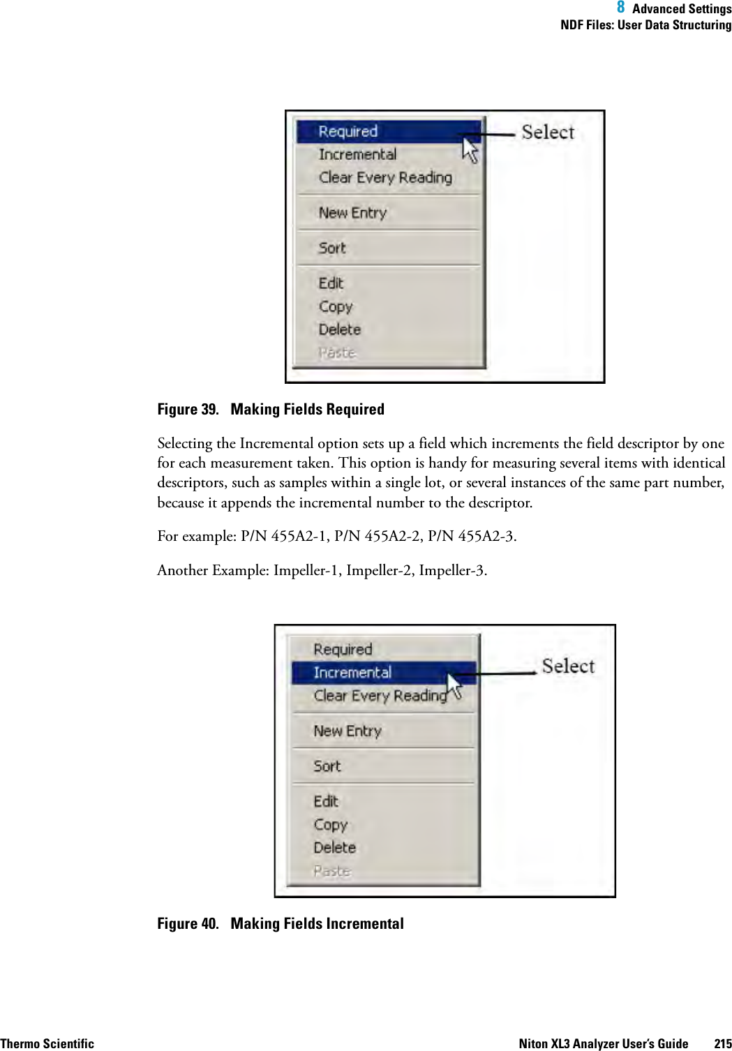
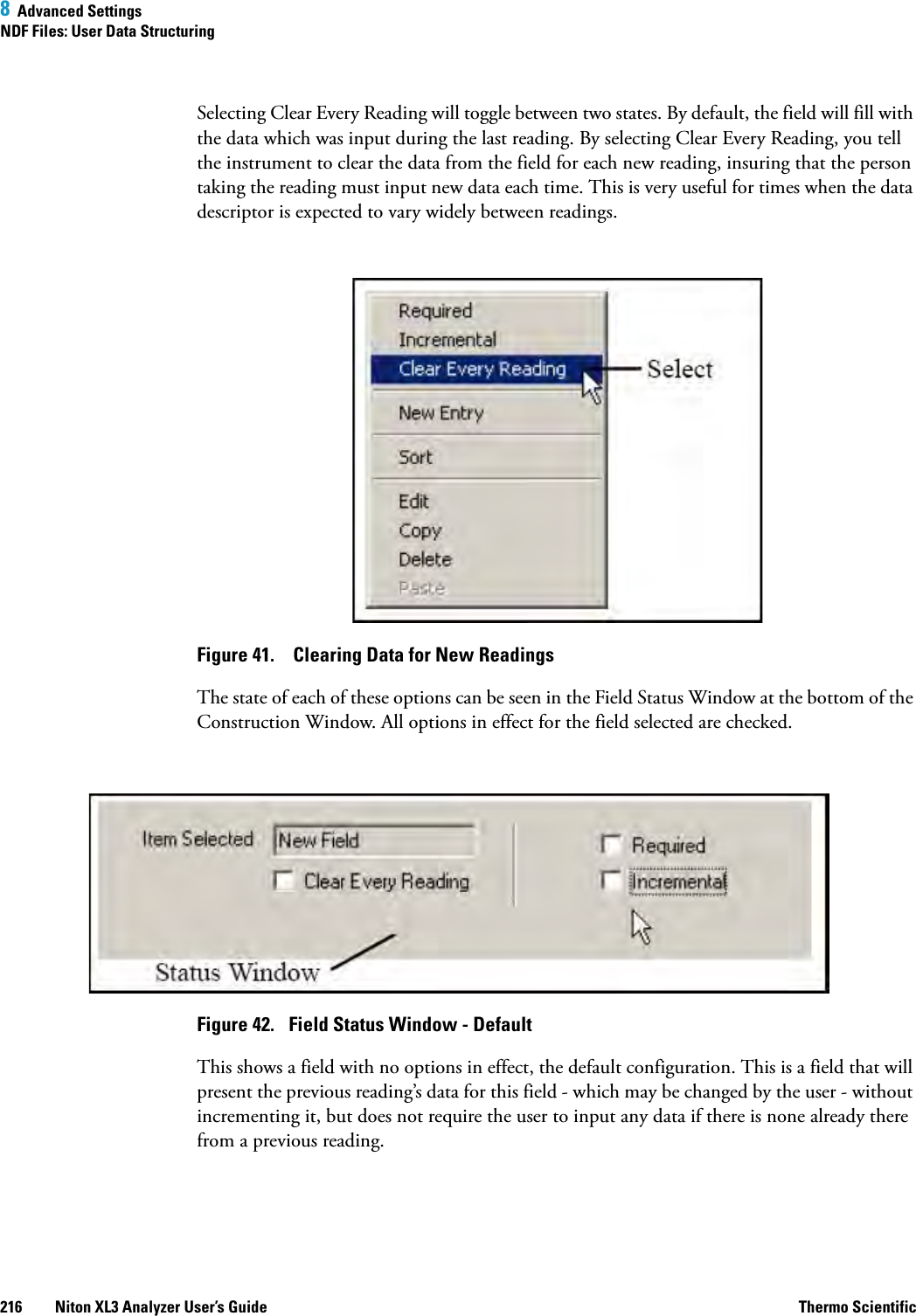
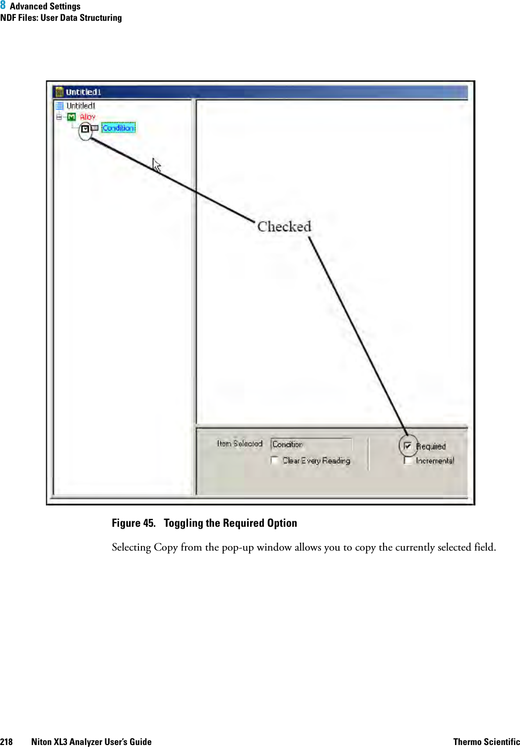
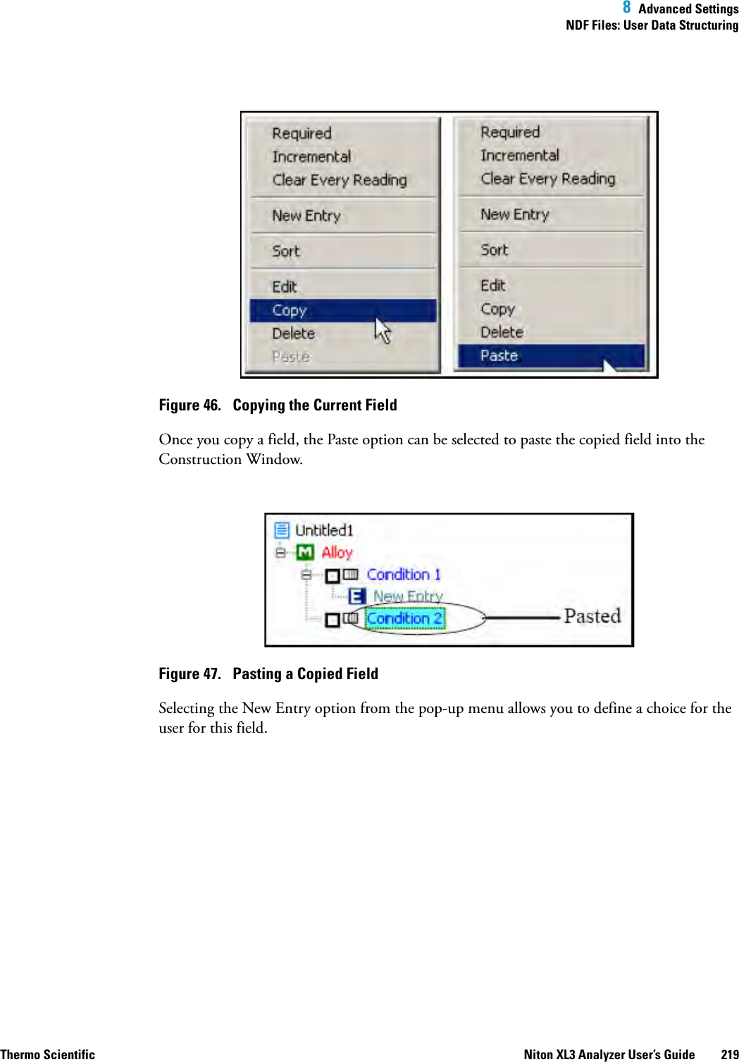
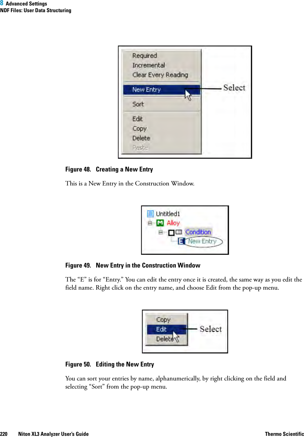
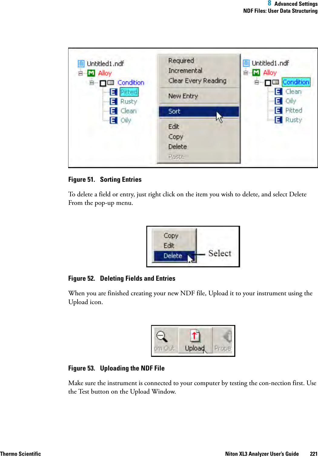
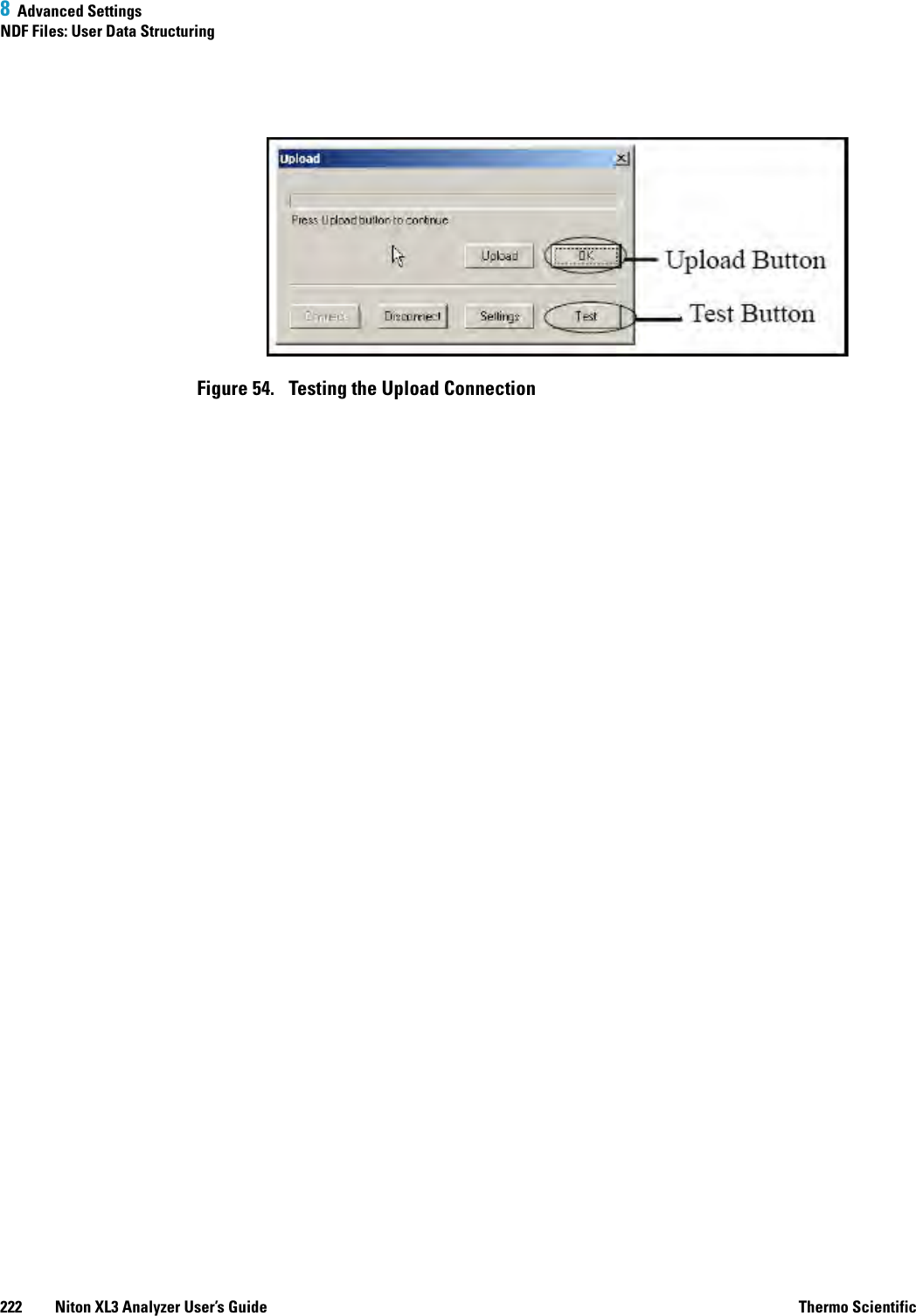
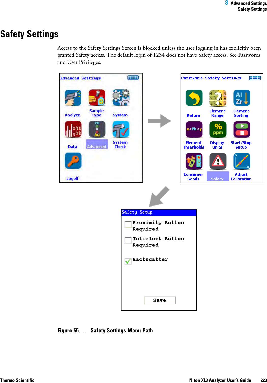
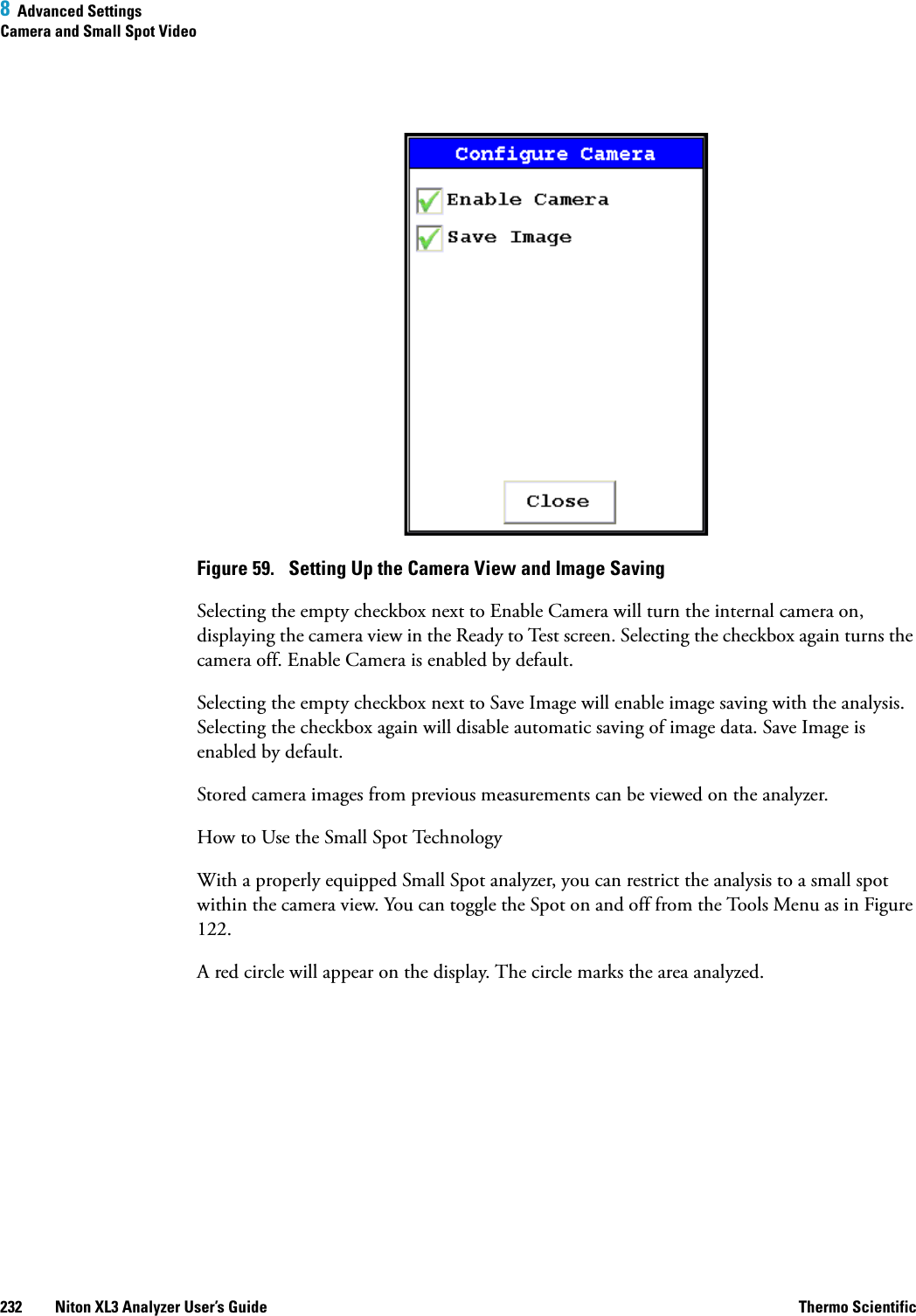
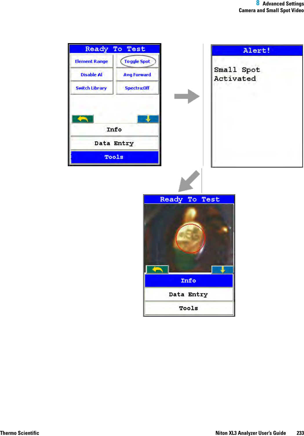
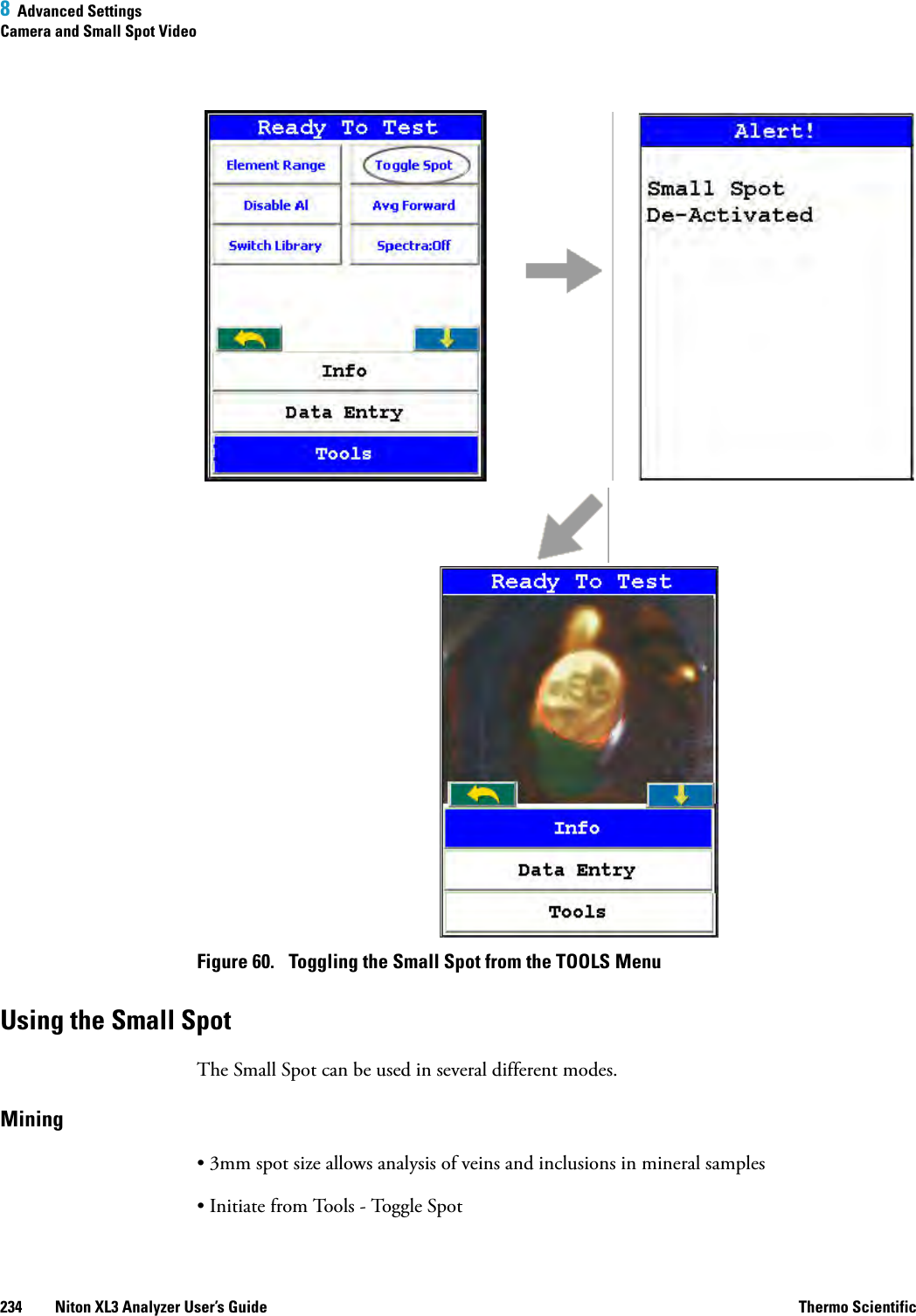
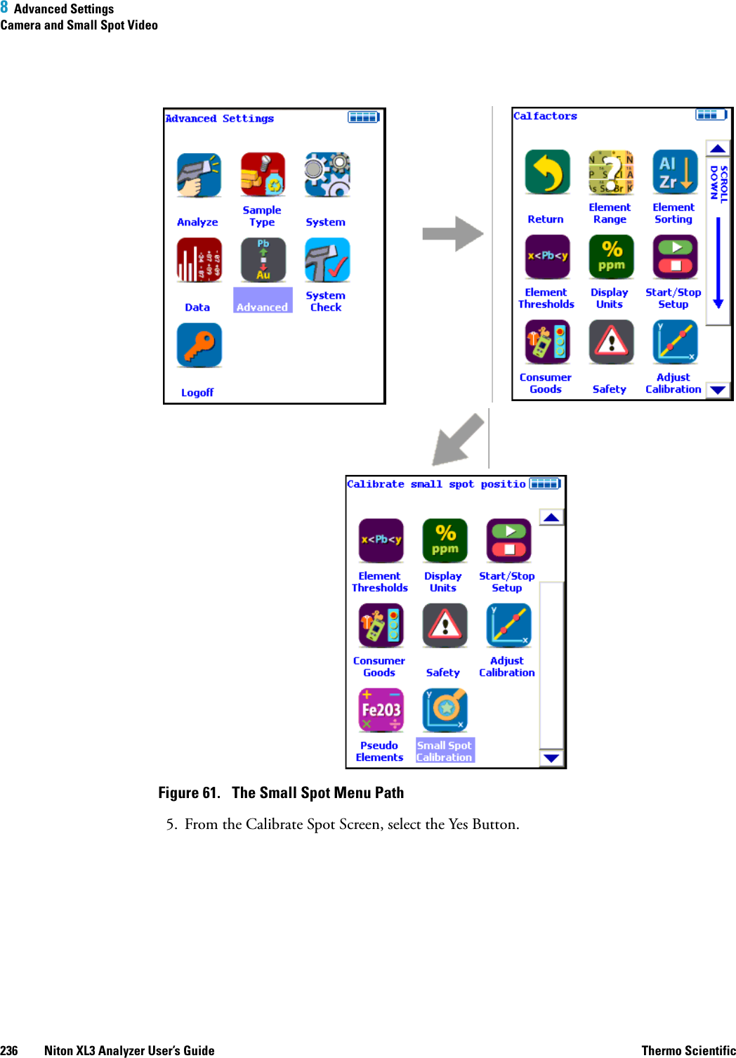
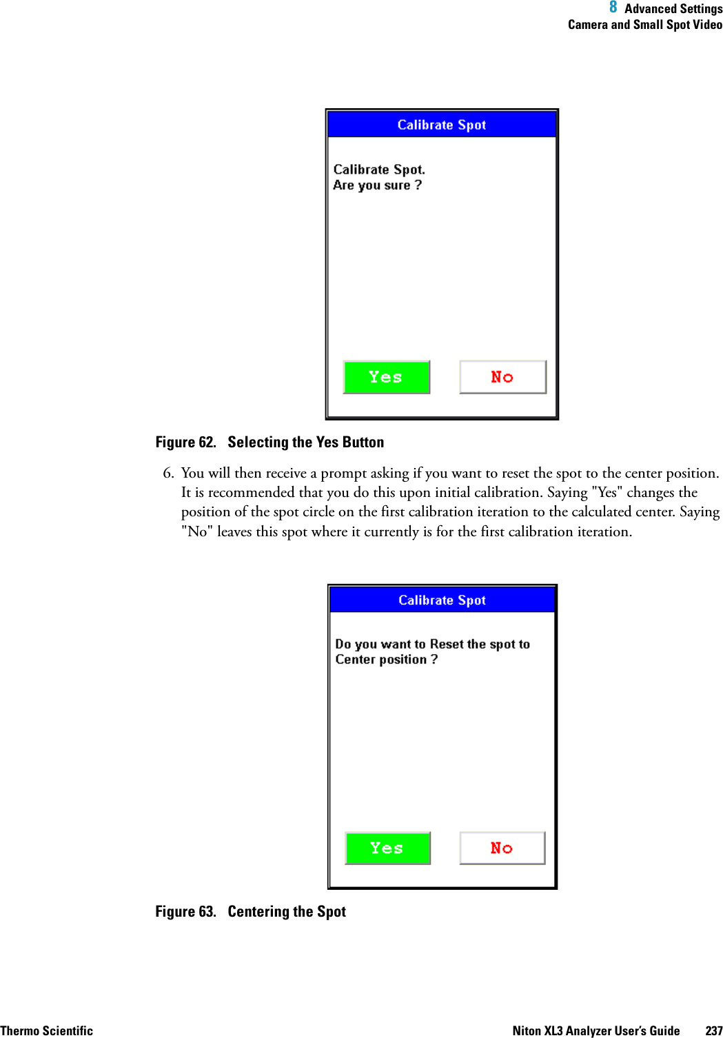
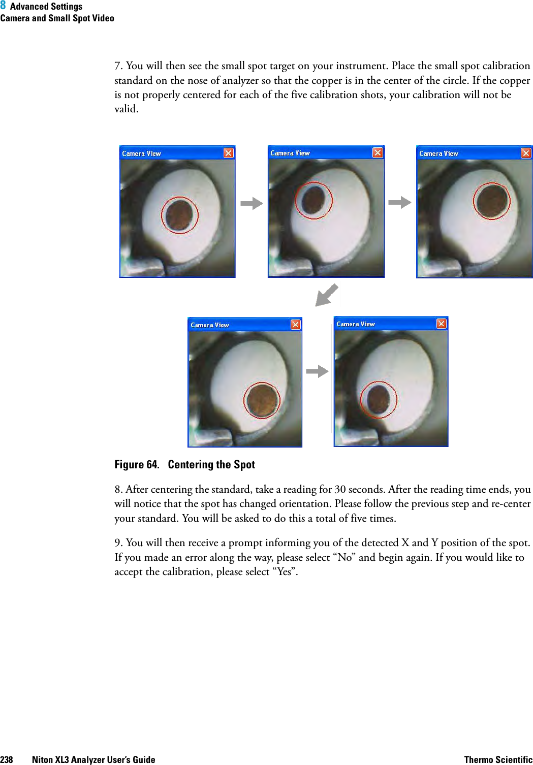
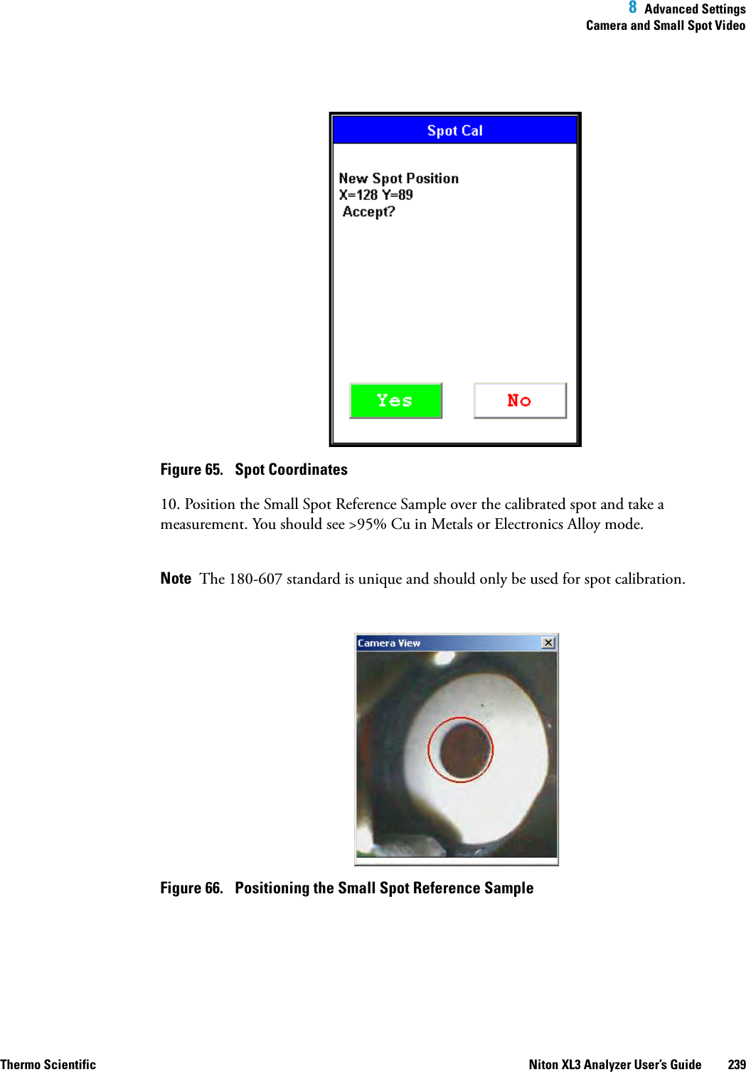
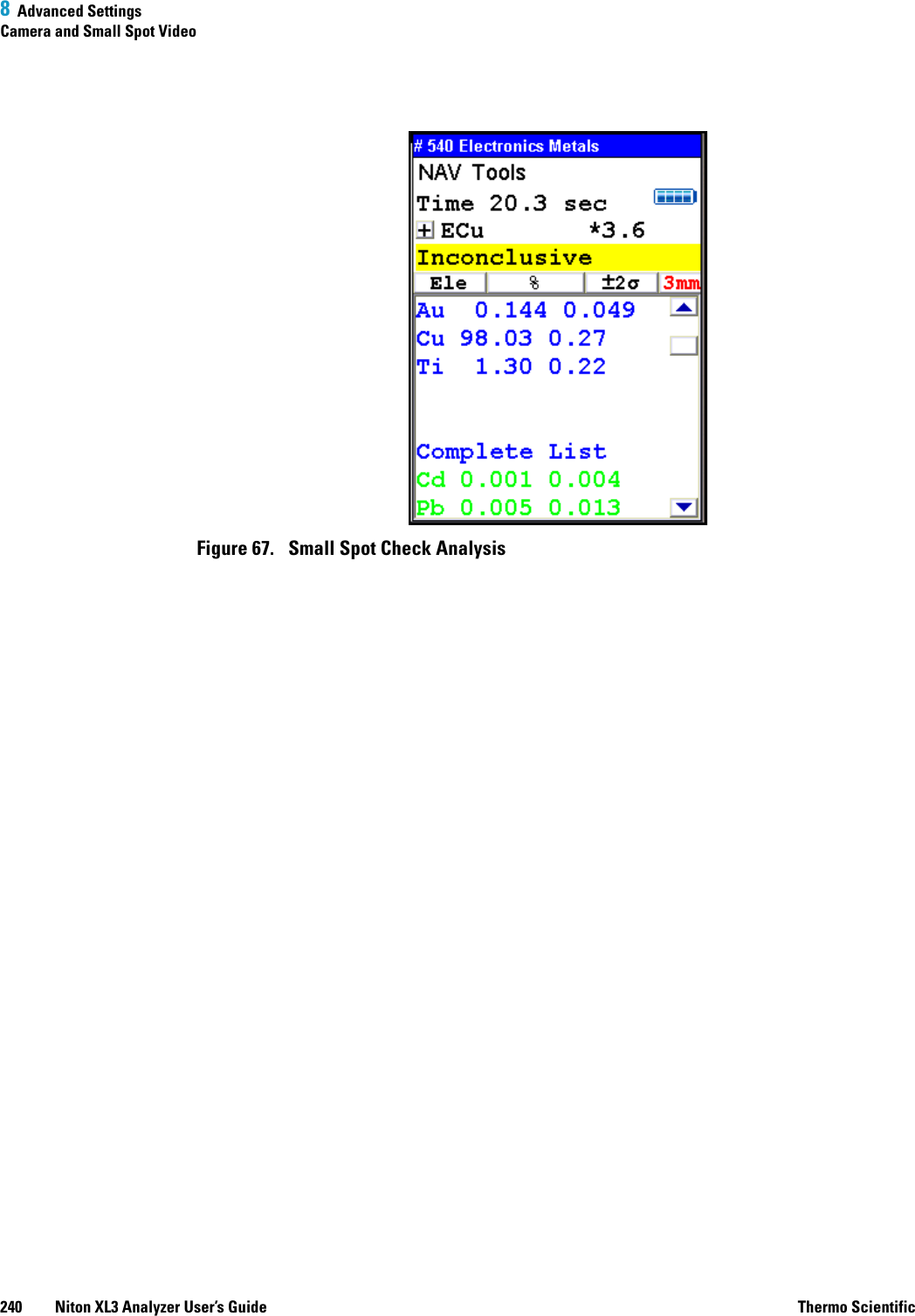
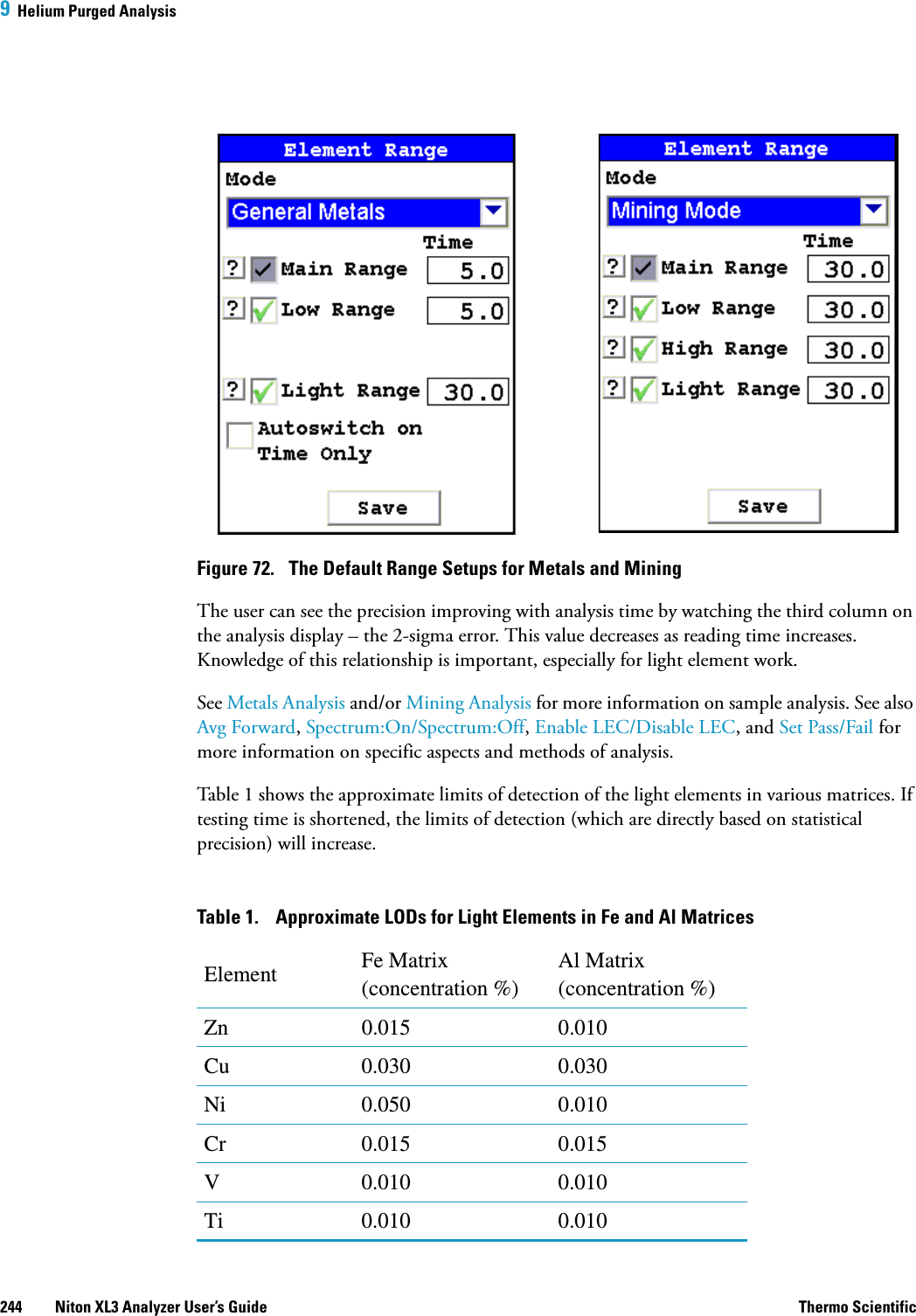
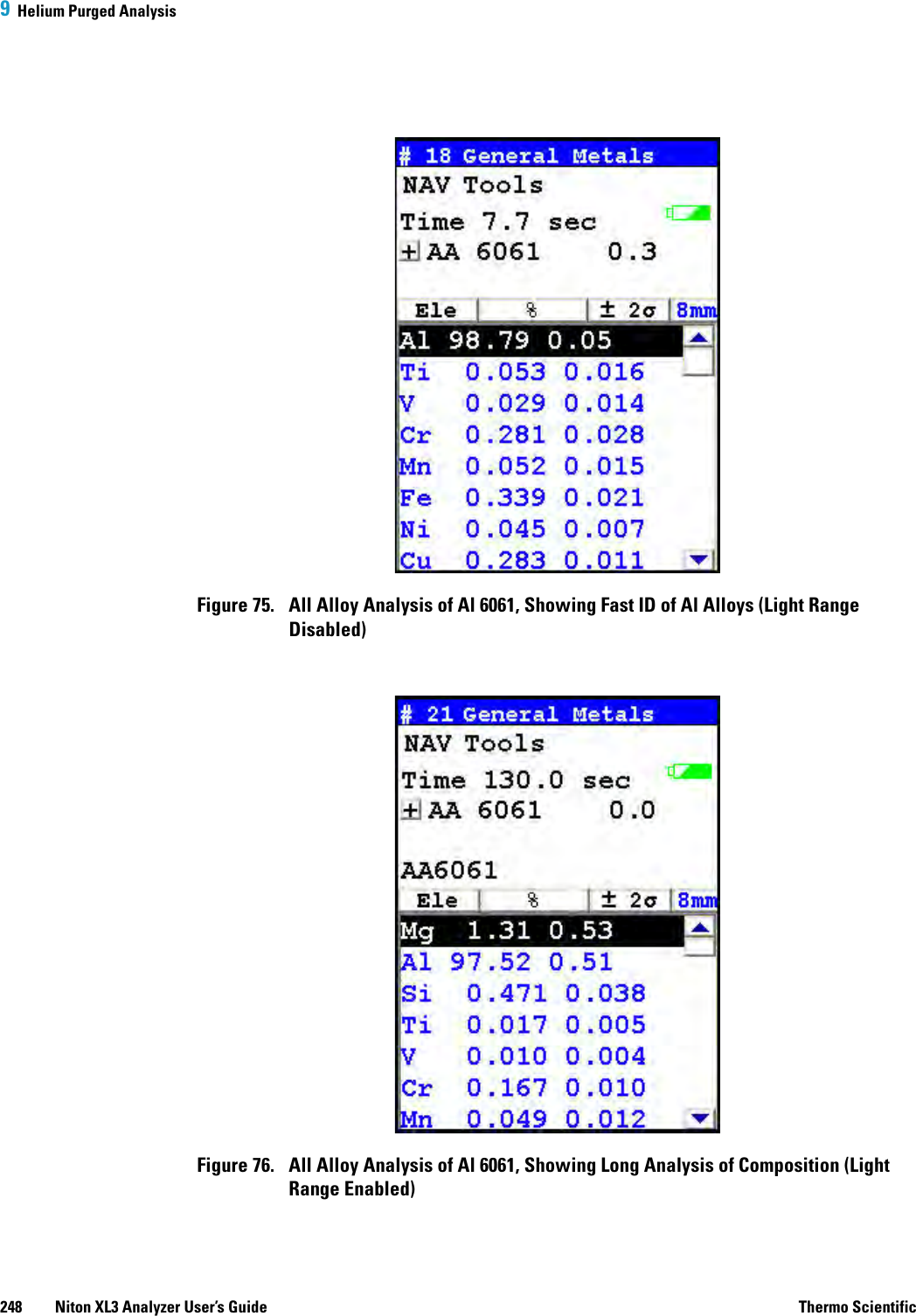
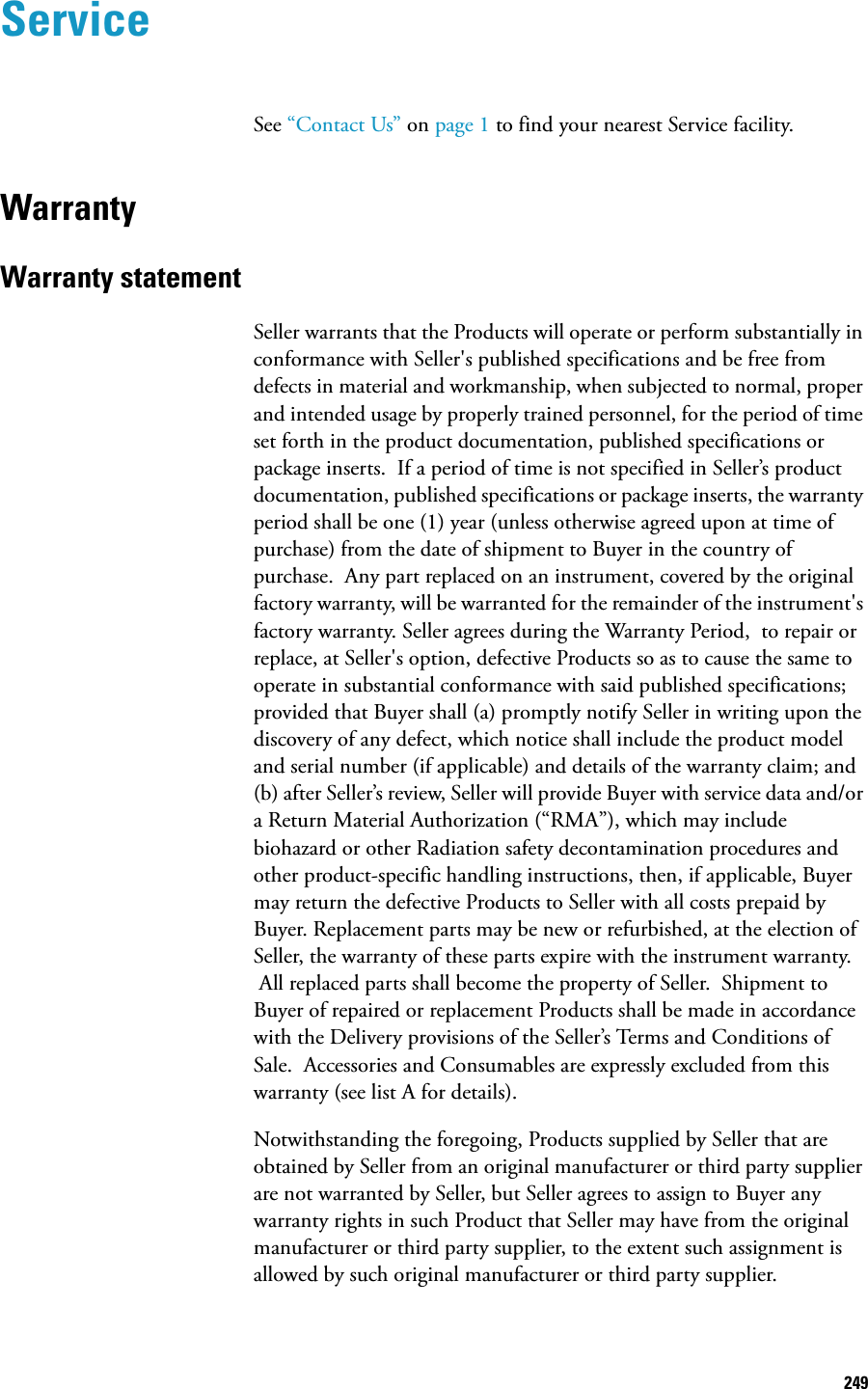
![8 Advanced SettingsTools Menu Options198 Niton XL3 Analyzer User’s Guide Thermo ScientificSwitch Library (Main)Selecting the Switch Library button from the Tools Menu will swap the currently loaded library with the other library on the analyzer. Selecting Switch Library again will switch them back.Enable/Disable AlNormally, the collective amount of unquantifiable light elements in alloy analysis - the "balance" - is assumed to be aluminum and labeled as such in the analysis. Selecting the Disable Al button from the Tools Menu will delete this "aluminum" from the analysis results, showing only the quantified elements. Selecting the Enable Al button, the default state, will label this "balance" as "aluminum".Thickness CorrectionPlastics, and polymers in general, unlike metals or soil, are very weak absorbers of X rays. This is because polymers are composed mainly of very light elements such as carbon and hydrogen. While just half a millimeter of steel will completely stop 23.1 keV energy X rays of cadmium, for example, it takes at least 10mm of plasticized PVC and as much as 100mm of polyethylene (PE) to do so. Fortunately, polymers that may contain cadmium (Cd), lead (Pb) and other restricted elements would also contain considerable quantity of elements such as antimony (Sb), bromine (Br), titanium (Ti), etc. Their presence results in much stronger absorption of X rays which means that, instead of 100mm, it takes only about 15mm of compounded PE to achieve saturation thickness for these X rays. If the thickness of analyzed polymer sample is less than 5mm for PVC or less than about 9mm for a “typical” PE, the measured intensity of X rays will be a function of both analyte concentration and sample thickness. This is why measurements performed on thin samples (less than saturation thickness) need to be corrected for thickness.How to apply Thickness Correction.In order for the instrument to apply thickness correction to the measured concentration results, the user must be using the Thickness Correction screen and enter the thickness of the analyzed plastic object expressed in [mm] before the measurement is initiated. The thickness may be entered with precision to the second decimal place, although in practice only one decimal place is sufficient for effective correction.](https://usermanual.wiki/Thermo-Scientific/XL3.User-Manual-pdf/User-Guide-2206063-Page-206.png)