Thermor 200TC HACCP Wireless Temperature Monitor User Manual TH1158 200TC BP IB 080708 ENG indd
Thermor Ltd. HACCP Wireless Temperature Monitor TH1158 200TC BP IB 080708 ENG indd
Thermor >
Users Manual
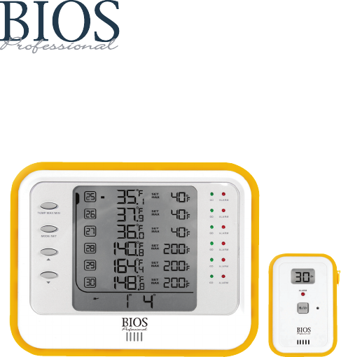
WIRELESS HACCP TEMPERATURE
MANAGER
INSTRUCTION MANUAL
IMPORTANT INFORMATION TO READ BEFORE OPERATING
THIS UNIT
System Requirements
:
Windows: 2000, XP & Vista
Excel: 2002, 2003, & 2007
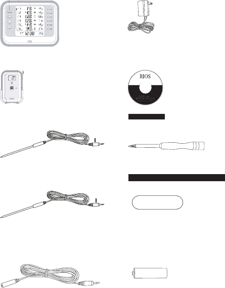
Before fi rst use, check contents of box for the following components:
Monitor
Adaptor – 204TC
6 x Temperature Sensors – 201TC
Datalogger Software – 209TC
4 x Cold Probes – 203TC (each)
Screwdriver
2 x Hot Probes – 202TC (each)
6 x Wall Mount Adhesive Strips
210TC
2 x 14’ Extension Cords – 208TC
(each)
18 x AAA Batteries
4 x AA Batteries
blue
red
1.0 Introduction
Congratulations on your purchase of the BIOS Professional Wireless HACCP
Temperature Monitor. This unit was designed with food safety and convenience
in mind.
Monitoring temperature of hot and cold foods throughout the day can be time
consuming and costly. This unit does all of the work, with accurate and precise
readings stored so that data can be uploaded onto a personal computer, and kept
for future reference.
1.1 Benefi ts of using the
BIOS Professional
HACCP Temperature
Monitor
• Reduce costs associated with managing HACCP
• Allows users to store detailed historical data
• Helps to reduce the risk of serving hazardous food
• Monitors the time food is in a food temperature danger zone
1.2 Features
The BIOS Professional Wireless HACCP Temperature Monitor is a wireless
digital temperature device which is capable of reading, displaying and monitoring
current temperatures from up to 30 temperature sensors. These long range
sensors can transmit data through fl oors and from “out of sight” storage areas.
Aside from current temperatures, the monitor’s
LCD screen
displays a real time
clock and calendar, as well as maximum and minimum pre-set temperature
settings.
An
audible alarm
sounds when temperatures fall out of the pre-programmed
range. In addition to the audio alert, green and red LED lights indicate
temperature status for each sensor. The delay function defers the alarm for a user
specifi ed period of 0, 15, 30, 45 or 60 minutes.
Every 15 minutes,
PC uploadable
temperature data for each sensor is logged.
Logged data is retrieved through the USB port and PC download software, as
provided.
1.3 Care of the Device
• Always wear a heat resistant glove to touch the stainless steel probe if being
used in an area where temperature is high.
• Wash stainless steel probes between uses, drying thoroughly.
• Do not submerge the probe in water. Moisture inside the probe’s plug or the
thermometer might cause an incorrect temperature reading. Always wipe the
probe’s plug dry before plugging it into the sensor.
• Do not subject the unit to excessive force, shock, dust, temperature or
humidity that may result in malfunction, shorter electronic life span, or
damage to the unit.
• Do not place the monitor in direct sunlight, or let it come into contact with
moisture or hot surfaces.
• The probe is a sharp metal object. Take care when handling to avoid injuries.
• Probes with red plugs are designed for monitoring high temperature while
probes with blue plugs are designed for monitoring low temperature. Do not
mix the usage of the two probes.
• Do not expose any part of the probe directly to open fl ames. This will damage
the temperature sensor.
• Clean the probe with water and a mild detergent. Do not use corrosive or
abrasive materials. Do not clean the probe in a dishwasher.
• To clean the monitor or temperature sensor, wipe with a damp cloth.
• Do not immerse the monitor or temperature sensor unit in water. If you spill
liquid over the monitor or temperature sensor unit, dry immediately with a
soft, lint-free cloth.
• Do not tamper with the internal components of the monitor or temperature
sensor units.
2.0 Getting Started
Power up the monitor using the AC/DC adaptor included with the kit, before
attempting to program. Insert 4 x AA batteries in the battery compartment on the
back of the monitor for back up purposes.
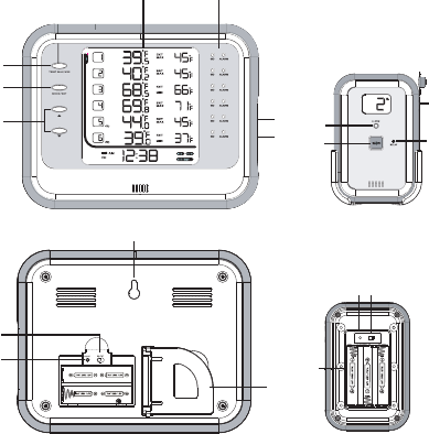
2.1 About the Wireless HACCP Temperature Monitor
This section describes the components of the unit.
Monitor
Front:
Temperature Sensor
Front:
Back:
Back:
Monitor
1. LCD Screen
2. Green/Red LED Light
3. Scroll Buttons
4. Mode/Set Button
5. Temperature Max/Min Button
6. USB Port
7. AC/DC Socket
8. °C/°F Switch
9. Reset Button
10. Wall Mount Hole
11. Swing Out Stand
Temperature Sensor
1. LCD Screen with Sensor Number
2. Alarm Delay Button
3. Mute/Sleep Button
4. Probe Socket
5. Red LED Light
6. Battery Compartment
7. Reset Button
8. Extension On/Off Slide Switch
10
8
11
9
87
6
RESET EXT
ON
OFF
1
5
4
35
32
4
6
1
7
2
2.2 About the LCD Screen on Monitor
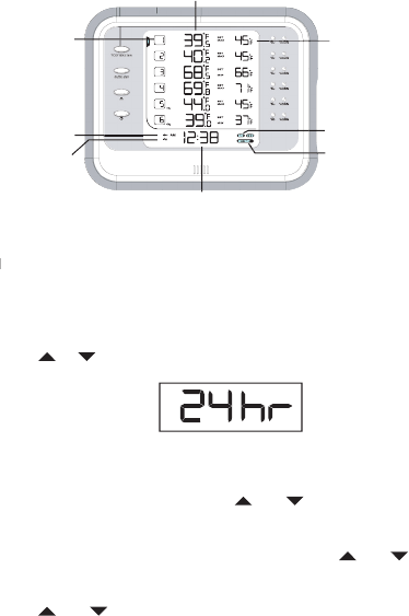
The LCD screen displays the sensor temperatures along with their actual and set
Max/Min temperatures. It also displays a real time clock and calendar, low/no
battery icon, AC/DC adaptor icon,
REG
istration mode icon, and
SET TEMP
mode
icon.
Actual Temperature
Set and Recorded Max/Min
Temperature
Sensor Number
Registration Mode Icon
Time / Date
AC/DC Adaptor
Icon
Low Battery Icon
Set Temperature
Mode Icon
3.0 Time & Date Setting
NOTE:
To maximize the benefi ts of this unit, accurate time and date should
NOTE: To maximize the benefi ts of this unit, accurate time and date should NOTE:
be set.
1. Press and hold
MODE/SET
until you hear a beep and the “24” begins to
fl ash.
2. Use the
or
arrow to choose either a 24 or 12 hr clock.
3. Press
MODE/SET
to confi rm.
4. Once the clock beings to fl ash, repeat steps 2 and 3 to program the time.
5. The year will begin fl ashing. Use the
and
arrows to choose the correct
year.
6. Press
MODE/SET
to confi rm.
7. “M” (month) and “D” (day) will begin to fl ash. Use the
and
arrows to
select the format in which you would like the date to be displayed. Press
MODE/SET
to confi rm.
8. Use the
and
arrows to program the month and day.
9. Press
MODE/SET
to confi rm.
4.0 Using an Extension Cord
An extension cord can be used if the cord on the probe is not long enough to
reach the desired area from where the sensor is mounted.
1. Plug extension cord into temperature sensor.
2. Plug probe into extension cord.
3. Use the slide extension ON/OFF switch to select Ext. ON.
NOTE:
If an extension cord is added after the sensor is registered, reset the
sensor by removing and re-inserting one battery.
5.0 Registering Temperature Sensors to Monitor
By registering each sensor to the monitor, you ensure that no cross
communication will occur. Each sensor will act independently to communicate its
temperature to the monitor.
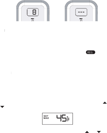
AL AR
M
AL AR
M
Registered
Not Registered
NOTE:
Ensure probe is fully inserted in sensor before registering. If using
NOTE: Ensure probe is fully inserted in sensor before registering. If using NOTE:
extension cord, ensure cord is inserted in sensor and probe is inserted in the
extension cord. Remove the back panel (using the screwdriver provided) from all
sensors that will be registered before starting registration.
1. Press
MODE/SET
once on the monitor, the
REG
icon (
) will appear.
2. Press and hold
MODE/SET
to enter registration mode. You will hear a beep
once it is confi rmed.
3. The current sensor number and dashes (--.-) will fl ash on the monitor.
4. Insert 3 x AAA batteries into the back of the sensor.
NOTE:
If no temperature sensor is registered within 1 minute the monitor will
NOTE: If no temperature sensor is registered within 1 minute the monitor will NOTE:
go back to normal mode.
5. Once the batteries are inserted into the sensor you will hear a long beep from
the sensor. If registration was successful, a number will appear on the LCD
screen of the sensor. This number is the number of the sensor (see section
12.0 Troubleshooting if a number is not displayed).
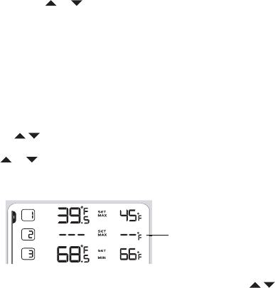
6. Once the sensor is registered, the current temperature will be displayed
on the monitor and the SET MAX temperature will fl ash. Use the
and
arrows to adjust the maximum temperature limit.* Press
MODE/SET
to
confi rm.
7. The
SET MIN
temperature will begin to fl ash. Use the
and
arrows to
adjust the minimum temperature limit.* Press
MODE/SET
to confi rm.
8. Repeat steps 4-7 to register remaining sensors.
9. Once registration is completed, press and hold
MODE/SET
to exit registration
mode.
*Press and hold
or
arrow for fast increment and decrement movement.
NOTE:
If at any time the monitor goes back to normal mode, follow steps 1
and 2 to get back to registration mode.
Once registering is complete, ensure monitor and sensor are in an upright
position (see section 10.0 for wall-mount instructions).
6.0 Deleting a Registration
Sensors will need to be de-registered if they are no longer required, or if they will
be used for a location different than that which it was previously programmed for.
IMPORTANT:
Both the monitor and sensor will need to be de-registered.
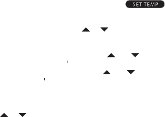
1. In registration mode (refer to section 5.0), press and
hold
both arrows on the
monitor (
) for 2 seconds to activate the de-registration function. Digits
on the fi rst row will fl ash.
2. Press
or
to select the sensor to be de-registered. The digits of that
selected sensor will fl ash. Press
MODE/SET
to confi rm, numbers will turn
into dashes.
Sensor has been
de-registered
3. Once de-registration is complete, press and hold both arrows (
)
to return to registration mode OR press and hold
MODE/SET
to return to
normal mode.
4. To de-register the sensor, remove 1 battery from the sensor.
5. While pressing the
MUTE/SLEEP
button on the front of the sensor, insert the
battery back into the battery compartment. You will hear a beep.
Continue to
hold the MUTE/SLEEP button while the beep sounds. Let go of button
after beep stops.
6. You will then see (- -) in the sensor display instead of a sensor number. When
the dashes are displayed the sensor has been de-registered successfully.
NOTE:
If you are not going to re-register a sensor, remove all batteries.
Sensor will then be ready for registration when required.
7.0 Max/Min Temperature Setting
You can set each sensor with a maximum and minimum temperature alarm.
Once a sensor falls out of the programmed range, both the sensor and monitor
will beep. A red light will fl ash on the monitor to indicate which sensor is out of
range.
NOTE:
The Min/Max temperature setting is done when the sensors are being
registered for the fi rst time. To change the Min/Max temperature settings follow
the steps below.
1. In normal mode, press
MODE/SET
until SET TEMP icon (
)
appears.
2. Press and hold
MODE/SET
to enter temp setting mode.
3. When the digits on the fi rst row fl ash, press
or
to select which sensor is
to be set.
4. Press
MODE/SET
to confi rm.
5. SET MAX temperature will begin fl ashing. Use the
and
arrows to
adjust the maximum temperature limit.
*
Press
* Press *
MODE/SET
to confi rm.
6. SET MIN temperature will begin fl ashing. Use the
and
arrows to adjust
the minimum temperature limit.
*
Press
* Press *
MODE/SET
to confi rm.
7. Repeat steps 3 through 6 to adjust the minimum/maximum temperature limits
for other sensors.
8. Press and hold
MODE/SET
to exit temp setting mode.
*
Press and hold
or
arrow for fast increment and decrement

8.0 Alarm delay operation
Users have the option of setting an alarm delay, so that once temperature falls
out of the programmed range, a timer will start counting down and the audio
alarm will not sound. If the temperature does not go back into the programmed
temperature range within the pre-set delay period, the alarm will sound once the
timer hits zero. This allows for temporary fl uctuations.
1. Press the DELAY key on the sensor to toggle between 0, 15, 30, 45 and 60
minutes. Select the delay time desired, display will show the delay time and
confi rm automatically after 5 seconds.
2. When sensor detects temperature has exceeded the programmed range, the
delay timer is triggered and begins counting down. The audio alarm will not
be triggered within the delay period.
3. Sensor will show “dE” by fl ashing every 0.5 seconds to indicate the delay
function is running. If temperature continues to exceed set range after the
delay period (e.g. 31 min), the alarm will sound on monitor and sensor.
NOTE:
Once alarm is triggered, the red LED on the sensor will fl ash every
NOTE: Once alarm is triggered, the red LED on the sensor will fl ash every NOTE:
second for the fi rst 2 minutes, and every 5 seconds after.
4. If temperature resumes within the programmed range during the delay period,
it will stop the delay timer immediately.
NOTE:
Monitor will show “dE” when temperature exceeds set range so that
NOTE: Monitor will show “dE” when temperature exceeds set range so that NOTE:
the user will know the delay period is running. Green LED will still fl ash to
show the operation is fi ne. If temperature continues to exceed set range after
the delay period (e.g. 31 min), monitor will show “Low” or “Hi” and red LED
will fl ash to indicate temperature is out of range.
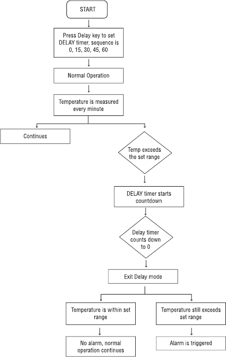
Alarm delay sequence

9.0 Display on Temperature Sensor
Each Temperature Sensor has a small LCD screen, which upon registration
displays a number. The corresponding number can be found on the monitor,
where the temperature of that sensor is displayed.
– Sensor is in sleep mode. To temporarily stop transmission from the sensor
to the monitor, press and hold the Zz button on the sensor until a beep is heard.
– Press the Zz button on sensor to mute the sensor and avoid an audio
alarm. When the sensor is set to mute, the only indication of an alarm is the red
LED light.
– When the low battery icon appears, batteries should be replaced.
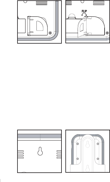
10.0 Sensors and Monitor Placement
IMPORTANT:
To ensure no signals are lost from sensor to monitor, make sure
that the monitor and sensors are always in an upright, vertical position.
NOTE:
To stand monitor on fl at surface, use built in stand located on the back of
the unit.
For positioning using a nail, screw or hook:
1. Fasten nail, screw or hook (not included) to wall.
2. When positioning the monitor, remove rubber stopper in the wall mount hole
located at the back of the monitor.
3. Hang unit on the wall using the wall mount hole on the monitor, and/or on the
wall mount bracket included with the sensor.
For positioning using double sided tape (sensor only):
IMPORTANT:
before positioning monitor or sensors, ensure wall surface is clean
and residue free.
1. Remove one piece of double sided tape from the sheet provided.
2. Stick the tape vertically across the center of a sensor.
3. Peel off the backing paper from the tape.
4. Position by pressing sensor fi rmly against the wall.
Monitor
Sensor
NOTE:
when installing the sensors in large refrigerators and/or freezers, it is
NOTE: when installing the sensors in large refrigerators and/or freezers, it is NOTE:
best to use the extension cord to mount the probe in the back half of the area
being monitored. Approximately half way from the fl oor to ceiling will give optimal
readings.
11.0 PC Download
IMPORTANT:
If you are using a Windows Vista operating system, follow the
directions below
before
installing the “Datalogger” software:
1. Click on your Start menu button.
2. Click on Control Panel.
3. Double click on User Accounts.
4. The line, “Turn User Account Control On or Off” will be displayed.
Click on this.
5. “
Use User Account Control (UAC) to help protect” will be displayed.
Remove the check mark from the box.
6. Restart your computer, then follow the rest of the instructions below.
Installing Software
1. Insert CD into your PC.
2. A window will open on the desktop.
3. Follow the steps to install the software.
NOTE:
If the window doesn’t open, click on the Start Menu. Click on My
Computer. The “Datalogger” software will be listed under Devices with Removable
Storage.
Connecting Unit to PC
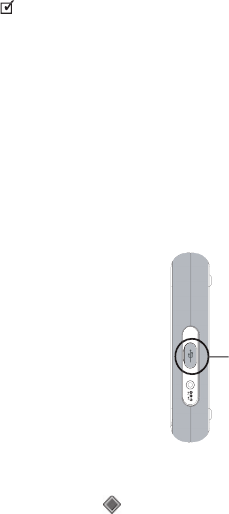
1. Once software is installed, plug the USB cable into the BIOS monitor and
then into your PC.
USB Port
2. Click on your Start menu button, go to “All Programs”, click on “Datalogger”
3. On the bottom right corner of your PC monitor screen you will see the
Datalogger icon (
3. On the bottom right corner of your PC monitor screen you will see the
).
4. The Datalogger icon will be grey when the monitor is not connected to the
PC. Once the monitor is connected to the PC the Datalogger icon will turn
green.
5. Right click on the icon, a menu bar will open. Click on “Start Upload”.
6. The data will start to upload from the monitor to the PC.
7. Once the upload is fi nished, open your “My Documents” folder. In this folder
there will be a folder named “Datalogger”. Open the “Datalogger” folder.
8. Open the Excel fi le named “Datalogger”. An excel document will open with a
blank template of the software sheet. A menu will open asking to Disable or
Enable Macros, click on Enable Macros.
9. A new excel document will open with the uploaded data. Ensure document is
saved before closing.
NOTE:
The Excel document will be named using the year, month, day and
time the upload was made. For example, if you uploaded the data on Dec. 12,
2007 at 3:06pm the fi le will be named 200712121506.xls
10. To insert the name of sensor locations, such as “Refrigerator”, fi nd the
“Location” fi eld on each worksheet. Type in the name of the sensor location.
11. To send a copy of a log fi le via email, open your email program. Start a new
email message and attach the fi le before sending to desired recipient.
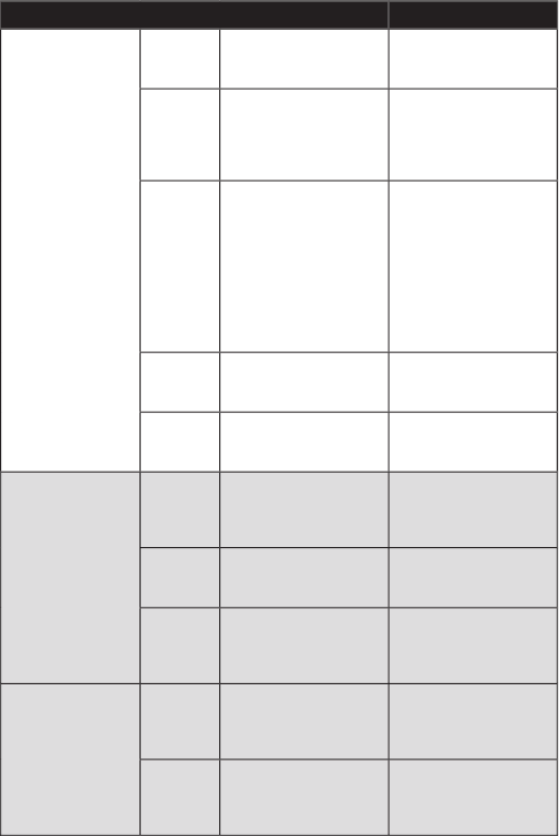
12.0 Troubleshooting
Unit Display Meaning Action
Monitor
----
Sensor is not registered
for that particular channel
Enter registration mode
and connect to sensor
unit
P
Probe is not connected
Ensure probe is properly
connected to sensor. If
it is not, de-register the
sensor (section 6.0) and
register again.
LS
Lost signal
Check battery of sensor.
Restart the temperature
sensor.
Check that the correct
probe is being used.
i.e.: Blue probe for
cold measurements
and red probe for hot
measurements
HI
Temperature exceeds
the display range or the
probe range
Check the actual
temperature of the
sensor location
Lo
Temperature is below
the display range or the
probe range
Check the actual
temperature of the
sensor location
Temperature Sensor
----
Sensor is not registered
Enter registration mode
on monitor and re-insert
batteries in the sensor for
registration
A
Alarm is on
Check sensor location.
Press MUTE/SLEEP to
resume normal operation
Z
Z
Sensor is in sleep mode
To exit sleep mode,
press and hold button
on sensor until a beep
is heard
“Datalogger”
Temperature Log
HHH
Current temperature
reading is over probe’s
max. temperature
capacity
– – –
LLL
Current temperature
reading is lower than
probe’s min. temperature
capacity
– – –
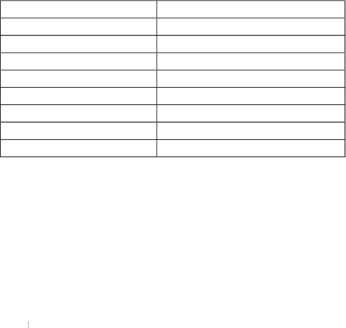
13.0 Specifi cations
Temperature Range:
-20°F to 300°F/-28°C to 148°C
Data Update Time:
15 minutes
Memory Capacity:
2 days for 30 sensors, 10 days for 6 sensors
Power Source:
Monitor: 120V AC/DC 15mA adaptor (included)
4 x AA batteries, 1.5V batteries
Sensor: 3 x AAA batteries, 1.5V batteries
Transmission Range:
100m (300 feet) in open area
Software Compatibility:
Windows: 2000, XP & Vista
Excel: 2002, 2003, & 2007
14.0 One Year Warranty
If this instrument proves to be defective in material or workmanship within one
year of purchase, it will be repaired or replaced without charge. This warranty
does not cover damage from misuse or tampering, including damage caused by:
• use contrary to the intended purpose of the device, or failure to observe the
instruction manual and/or the care instructions
• accidents or normal wear
• use of unsuitable accessories
• external infl uences such as damage during transport, damage caused by
vibration, excess heat, water, moisture or acids
NOTE:
This warranty expires if repairs or modifi cations are undertaken by third
NOTE: This warranty expires if repairs or modifi cations are undertaken by third NOTE:
parties or unauthorized persons.
To place a warranty claim, contact Customer Service at the address and phone
number below.
Thermor Ltd.
16975 Leslie Street
Newmarket, ON L3Y 9A1
www.thermor-ins.com
1-800-387-8520
15.0 FCC Statement
This device complies with Part 15 of the FCC Rules. Operation is subject to the
following two conditions: (1) This device may not cause harmful interference, and
(2) This device must accept any interference received, including interference that
may cause undesired operation.
Warning:
Changes or modifi cations to this unit not expressly approved by the
party responsible for compliance could void the user’s authority to
operate the equipment.
NOTE:
This equipment has been tested and found to comply with the limits
for a Class B digital device, pursuant to Part 15 of the FCC Rules. These
limits are designed to provide reasonable protection against harmful
interference in a residential installation. This equipment generates, uses
and can radiate radio frequency energy and, if not installed and used in
accordance with the instructions, may cause harmful interference to radio
communications.
However, there is no guarantee that interference will not occur in a
particular installation. If this equipment does cause harmful interference
to radio or television reception, which can be determined by turning the
equipment off and on, the user is encouraged to try to correct the
interference by one or more of the following measures:
Reorient or relocate the receiving antenna.
Increase the separation between the equipment and receiver.
Connect the equipment into an outlet on a circuit different from that to
which the receiver is connected.
Consult the dealer or an experienced radio/TV technician for help.
DECLARATION OF CONFORMITY
The following information is not to be used as contact for support or sales.
Please call our customer service number (listed on our website at
www.oregonscientific.com), or on the warranty card for this product) for all
inquiries instead.
We
Name: Oregon Scientific, Inc.
Address: 19861 SW 95th Ave.,Tualatin, Oregon 97062 USA
Telephone No.: 1-800-853-8883
declare that the product
Product No.: 200TC
Product Name: HACCP Wireless Temperature Monitor
Manufacturer: IDT Technology Limited
Address: Block C, 9/F, Kaiser Estate, Phase 1,41 Man Yue St.,
Hung Hom, Kowloon,Hong Kong
is in conformity with Part 15 of the FCC Rules. Operation is subject to the following
two conditions: 1) This device may not cause harmful interference. 2) This device
must accept any interference received, including interference that may cause
undesired operation.