User manual
1
atmosphere
Jumbo Weather Monitor
Moniteur Météorologique Géant
Instruction Manual / Mode d’emploi
2
B.
A.
O.
C. F.
D. E.
G.
H.
I.
J.
K
L.M.N.
1. 2.
3.
6.
8.
5.
7.
4.
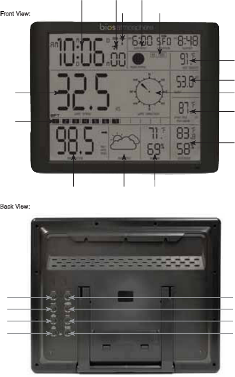
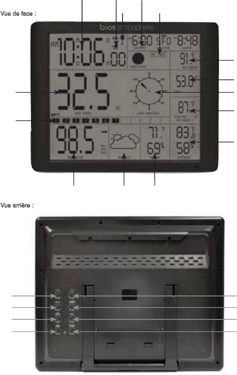
Front View:
Back View:
Thank you for purchasing the BIOS Atmosphere 2.0 Jumbo Weather Monitor
3
Jumbo Weather Monitor
Instruction Manual
Monitor Front
A. Wind Speed
B. Time and Date
C. Alarm
D. Radio Controlled clock with auto DST
E. Tide Indicator
F. Sunrise and Sunset
G. Heat Index / Wind chill
H. Wind Direction
I. Wind Gust
J. 24 Hour Maximum Outdoor Temperature
K. Outdoor Temperature and Humidity
L. Indoor Temperature and Humidity
M. Weather Forecast Icon
N. Barometric Pressure
O. Beaufort Wind Scale
Monitor Back
1. Clock Button
2. C/F Button
3. Mode/Set Button
4. Alarm/Weather Set Button
5. Gust/Wind Max Button
6. Snooze Button
7. Temperature/Max/Min Button
8. DST On/Off/ RF Search Button
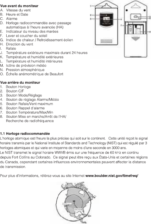
1.1 Radio Control Clock (RCC)
RCC has the most accurate time within the continent. This unit receives the time signal
transmitted by the National Institute of Standards and Technology (NIST) which is regulated
by 3 atomic clocks and in average deviates less than 1 second in 3000 years.
NIST transmits the time signal (WWVB, 60kHz) continuously from Fort Collins, Colorado. This
signal can be received in the USA and parts of Canada, however some environmental effects
may affect the transmitting distance.
For more information please see www.boulder.nist.gov/timefreq/
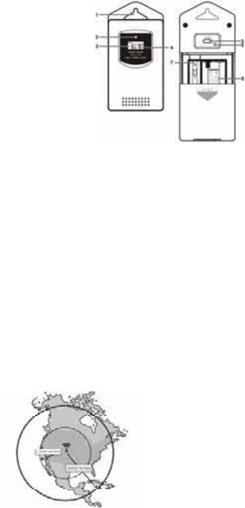
1: Wall Mount Hole
2: Transmission Indication LED
3: Temperature
4: Humidity
5:"C/F" button
6:"RESET" button
7: Wind Sensor Plug
8: Battery Compartment
Included:
1 - Jumbo Weather Monitor
2 - Remote Sensor
3 - Wind Sensor with Cable
4 - Wind Sensor accesories
4
2.0 Getting Started:
2.1 BIOS Atmosphere 2.0:
+–
RESET button located at the rear of the main unit, the main unit is
now ready for use
2.2 Outdoor Remote Sensor
+–
3.0 Installation
3.1 BIOS Atmosphere 2.0
the back of the unit.
3.2 BIOS Atmosphere 2.0 sensor
The remote sensor should be securely mounted onto a horizontal surface.
NOTE: Transmission between the receiver and transmitter can reach up to 80m in an open area
without any interfering obstacles such as buildings, trees, vehicles, high voltage lines, etc.
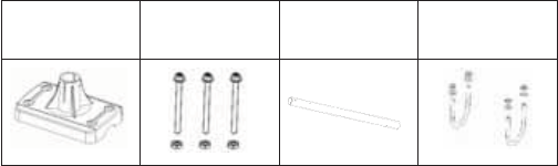
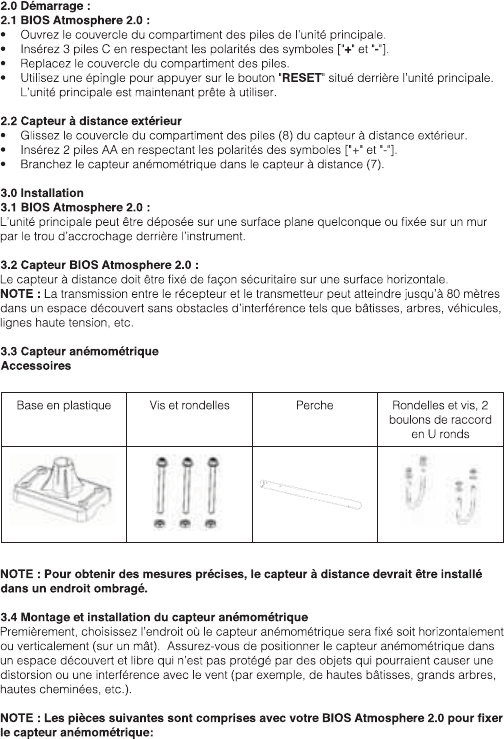
3.3 Wind Sensor
Accessories
Plastic Base Screws and Washes Pole Washes & Screws,
X2 Round U-shape
bolts
NOTE: The remote sensor should be placed in a shaded area for accurate readings.
3.4 Mounting and Setup for the Wind Sensor
First, choose whether the wind sensor will be mounted vertically or horizontally (on a mast).
Make sure that you position the wind sensor in a free, open area that is not protected by
objects, which may distort or interfere with the wind (e.g. large buildings, trees, chimney,
etc.).
NOTE: The following contents have been included with your BIOS Atmosphere 2.0 for
mounting the wind sensor:
5
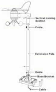
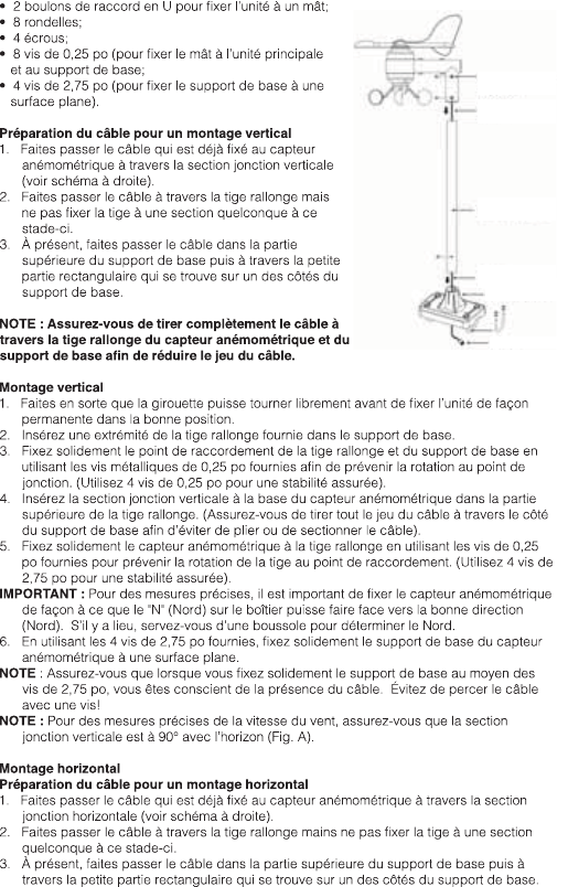
Cable Preparation for Vertical Mounting
1. Run the cable that is already fastened to the wind
sensor through the vertical joining section (see
right).
2. Run the cable through the extension pole but do not
secure the pole to any sections yet.
3. Now run the cable through the top of the base-
bracket and then through the small rectangular
section found on one side of the base-bracket.
NOTE: Make sure that you completely pull the cable
through the wind sensors extension pole and base-
bracket to reduce the amount of slack on the cord.
Vertical Mount
1. Make sure that the wind vane can rotate freely
before fastening the unit permanently into position.
2. Insert one end of the extension pole provided into
the base-bracket.
3. Secure the connection point of the extension pole
and base-bracket using the 0.25” metal screws
provided to prevent rotation at the joining point.
(Use 4 x 0.25” screws to ensure stability).
4. Insert the vertical joining section on the bottom of the wind sensor into the top of the
extension pole. (Ensure that you pull all cable slack through the side of the base-bracket
to prevent creasing or cutting the cable).
5. Secure the wind sensor to the extension pole using the 0.25” screws provided to make
sure that the pole connection does not rotate. (Use 4 x 2.75” screws to ensure stability).
IMPORTANT: For accurate readings, it is important to mount the wind sensor so that the
compass to determine north.
NOTE: Make sure that when you are securing the base bracket with the 2.75” screws, you
are aware of the cable. Prevent driving a screw through the cable!
NOTE: For proper wind speed measurement ensure the vertical joining section is at 90º the
horizon
(Fig.A).
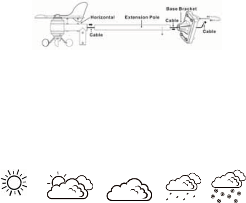
Horizontal Mounting
Cable Preparation for Horizontal Mounting
1. Run the cable that is already fastened to the wind sensor through the horizontal joining
section (see below).
2. Run the cable through the extension pole but do not secure the pole to any sections yet.
3. Now run the cable through the top of the base-bracket and then through the small
rectangular section found on one side of the base-bracket.
NOTE: Make sure that you completely pull the cable through the wind sensor’s extension pole
and base-bracket to reduce the amount of slack on the cord.
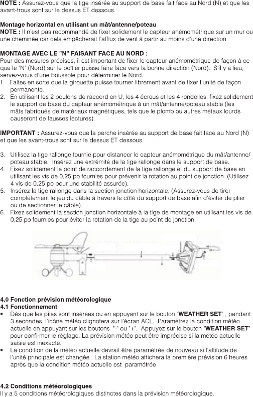
Horizontal mount - using a mast/antenna/pole
NOTE: It is not recommended to secure the wind sensor horizontally from a wall or chimney
6
MOUNT WITH “N” FACING NORTH:
N” (north) on
the casing is facing the correct direction (north). If necessary, use a standard compass to
determine north.
1. Make sure that the wind vane can rotate freely before fastening the unit permanently.
2. Using the 2 x U-bolts, 4 x nuts and 4 x washers, secure the base-bracket of the wind
sensor to a stable mast/antenna/pole. (Masts made of magnetic materials, such as lead or
other dense metals will cause faulty readings).
IMPORTANT: Make sure that the pole insert of the base-bracket is facing north (N) and pilot
holes are on the top AND bottom.
3. Use the extension pole provided to distance the wind sensor from the stable mast/
antenna/pole. Insert one end of the extension pole into the base-bracket.
4. Secure the connection point of the pole extension and base-bracket using the 0.25” screws
provided to prevent rotation at joining point. (Use the 4 x 0.25” screws to ensure stability).
5. Insert the pole extension into the horizontal joining section. (Ensure that you pull all cable
slack through the side of the base-bracket to prevent creasing or cutting the cable).
6. Secure the horizontal joining section to the mount pole using the 0.25” screws provided to
make sure that the pole connections does not rotate.
4.0 Weather Forecast Function
4.1 Operation
WEATHER SET” button for 3 seconds, the
-” or
+WEATHER SET
may not be accurate if the current weather entered is not correct.
weather status is entered.
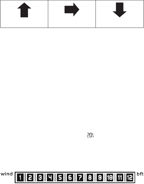
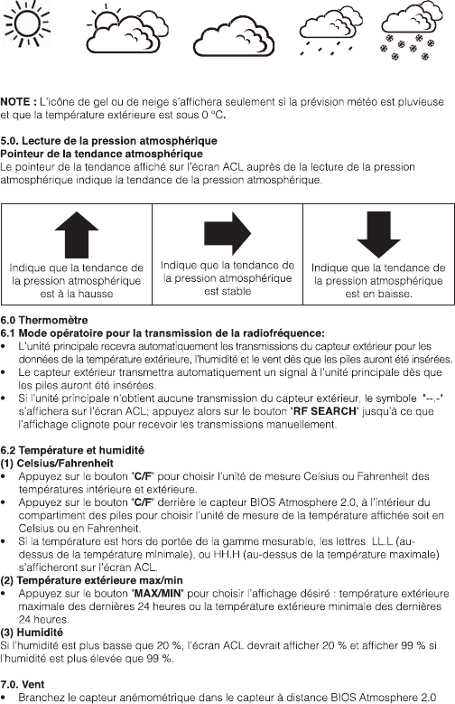
4.2 Weather Conditions
There are 5 different weather conditions in the weather forecast.
NOTE: The Freezing or snow icon will only appear if the weather forecast is Rainy and the
outdoor temperature is below 0°C.
SUNNY PARTLY CLOUDY CLOUDY RAINY STORMY
7
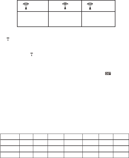
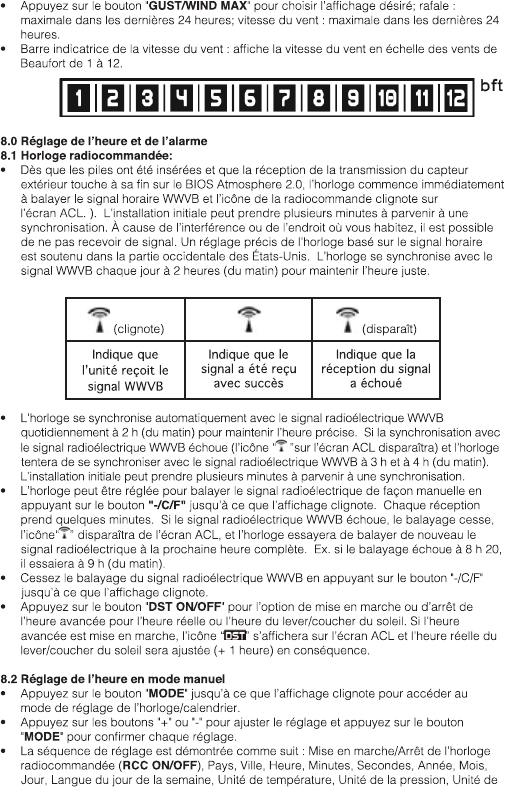
5.0. Barometric Pressure Reading
Barometric Trend Pointer
The trend pointer displayed on the LCD beside the Barometric Pressure reading indicates the
trend of the Barometric pressure.
Indicates the barometric
pressure trend is rising
Indicates the barometric
pressure trend is steady Indicates the barometric
pressure trend is falling
6.0 Thermometer
6.1 RF Transmission Procedure:
temperature; humidity & wind information after the batteries have been inserted.
been inserted.
- - . –RF SEARCH” bu to
receive transmissions manually
6.2 Temperature & Humidity
(1) Celsius / Fahrenheit
°C /°F” button to select indoor & outdoor temperature in Celsius or Fahrenheit
mode.
°C /°F” button on the rear of the BIOS Atmosphere 2.0 remote sensor, inside the
battery compartment, to select the temperature to be displayed in Celsius or Fahrenheit mode
or HH.H (beyond the maximum temperature) will be shown on the LCD.
(2) Max/Min Outdoor Temperature
MAX/MIN” button to select the desired view: past 24 hours maximum outdoor
temperature or past 24hrs minimum outdoor temperature.
(3) Humidity
If the humidity is lower than 20%, the LCD would display , and display 99% if the humidity
is higher than 99%
7.0. Wind
into the BIOS Atmosphere 2.0 remote sensor.
GUST/WIND MAX” button to select the desired view; gust: past 24 hrs
maximum, wind speed: past 24hrs maximum wind speed
8
8.0 Time and Alarm Setting
8.1 Radio Controlled Clock:
transmission from the outdoor sensor, the clock automatically starts to scan the WWVB
synchronize. It is possible not to receive the signal due to interference, or the area where
we you live. Accurate adjustment of the clock based on time signal is supported in the
continental USA. The clock automatically synchronizes with the WWVB every day at 2:00
am to maintain accurate time keeping.
(disapears)
Indicates unit
is receiving the
WWVB signal
Indicates signal
has been received
successfully
Indicates signal
reception has
failed
maintain accurate time keeping. If synchronization with the WWVB radio signal fails,
” icon on the LCD will disappear and the clock then attempts to synchronize with the
WWVB radio signal at 3 am and 4am. Initial setup may take several minutes to synchronize.
-/ (C/F)” button until
es several minutes. If the WWVB signal reception fails,
” icon will disappear from the LCD) and the clock will then attempt to
scan the radio signal again on the next full hour. E.g. if scanning failed at 8:20a.m., it will
scan again at 9:00a.m.
-/ °C /°F
DST ON/OFF” button selects to turn on or off DST (Daylight Saving Time)
” will be
displayed on the LCD, and the current sunset/sunrise time would be adjusted (+ 1 hour)
accordingly.
8.2 Manual Time Setting
MODE
+-” button to adjust the setting and preMODE
setting.
RCC ON/OFF, Country, City, Hour, Minutes,
Second, Year, Month, Day, Day of Week Language, Temperature Unit, Pressure Unit,
Wind Speed Unit.
following table.
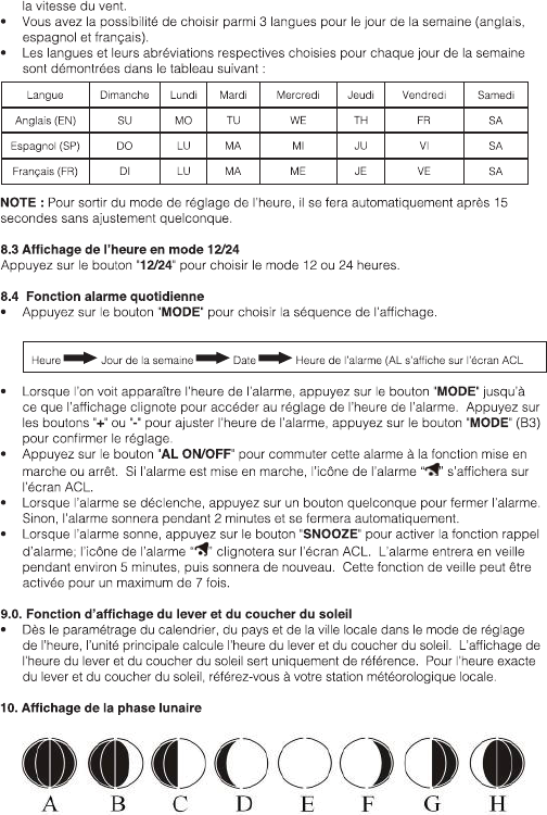
Language Sunday Monday Tuesday Wednesday Thursday Friday Saturday
English, EN SU MO TU WE TH FR SA
Spanish, ES DO LU MA MI JU VI SA
French, FR DI LU MA ME JE VE SA
NOTE: The Time Setting Mode will automatically exit in 15 seconds without any adjustment.
9
8.3 12/24 Hour Display mode:
12/24” button to select 12 or 24 hours mode.
8.4 Daily Alarm Function:
MODE” button to select to view
Time Day of Week Date Alarm Time (AL Display on LCD)
MODE”ter Alarm Time
+-MODE” button to
AL ON/OFF” button to switch that alarm ON or OFF
” will be shown on the LCD.
minutes, and stop automatically.
SNOOZE” button to activate the snooze function, the alarm
alarms again. This snooze function can be enabled for a maximum of 7 times.
9.0. Sunrise/Sunset Display Function
unit calculates the time of Sunrise/Sunset. The Sunrise & Sunset time display is just for
reference only. For exact Sunrise & Sunset time, please refer to your Local Weather
Station
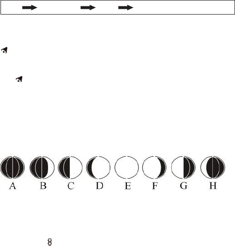
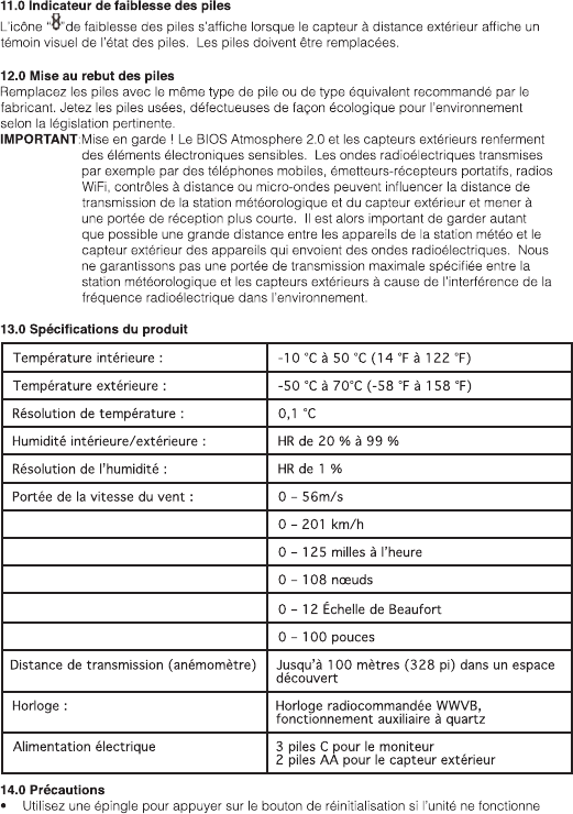
10. Moon Phase Display
11.0 Low Battery Indication
”will appear indicating that the outdoor remote sensor is in a low
battery status. The batteries should be replaced.
12.0 Battery Disposal
Dispose of old, defective batteries in an environmentally friendly manner in accordance with
the relevant legislation.
IMPORTANT: Warning! The BIOS Atmosphere 2.0 and the outside sensors contain sensitive
electronic components. Radio waves transmitted e.g. from mobile telephones,
transmission distance of the weather station and the outside sensor and lead to
a shorter reception range. It is therefore important to keep as great distance as
possible between the devices of the weather station and the outside sensor and
A: New Moon
D: Waxing Gibbous
G:Last Quarter
B: Waxing Crescen
E: Full Moon
H: Waning Crescent
C: First Quarter
F: Waning Gibbous

10
the devices which send out radio waves. We do not guarantee the maximum
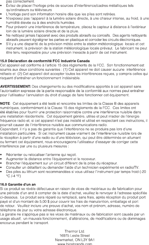
Indoor Temperature: -10°C to 50°C (14°F to 122°F)
Outdoor Temperature: -50°C to 70°C (-58°F to 158°F)
Temperature Resolution: 0.1°C
Indoor & Outdoor Humidity: 20% - 99% RH
Humidity Resolution: 1% RH
Wind speed range: 0 – 56m/s
0 – 201 km/h
0 – 125 mph
0 – 108 knot
0 - 12 Beaufort
0 – 100 inch
Transmission (Anemometer): up to 100 meters (328 feet) in open area
Clock: WWVB Radio-Controlled, Quartz back-up
Power: C x 3 pieces for the monitor
AA x 2 pieces for outdoor sensor
14.0 Precautions
sets.
sunlight and rain
cleaning agents may scratch plastic parts and corrode electronic circuits
unit, the Local Weather Station’s forecast should prevail. The manufacturer will not take
responsible for incorrect forecasting from this unit
15.0 Industry Canada/FCC Statement
Operation is subject to the following two conditions: (1) this device may not cause
interference, and (2) this device must accept any interference, including interference that may
cause undesired operation of the device.
WARNING:
NOTE
This device complies with Part 15 of the FCC rules. Operation is subject to the following two conditions: 1) this device
may not cause harmful interference, and 2) this device must accept any interference received, including interference
that may cause undesired operation.
11
digital device, pursuant to Part 15 of the FCC Rules. These limits are designed to provide
accordance with the instructions, may cause harmful interference to radio communications.
However, there is no guarantee that interference will not occur in a particular installation. If
interference by one or more of the following measures:
is connected.
°C / -4°F)
16.0 One Year Warranty
If this product proves to be defective in material or workmanship within one year of purchase,
please return it to the address below. It will be repaired or replaced without charge upon
receipt of the unit prepaid with $5.00 to cover handling, packaging and return postage.
Please include proof of purchase, your full name, address, daytime phone number or email
address.
This warranty does not apply if the defect or malfunction is a result of user abuse, misuse,
Thermor Ltd.
16975 Leslie Street
Newmarket, ON L3Y 9A1
www.biosbrands.com
1-800-387-8520
12
B.
A.
O.
C. F.
D. E.
G.
H.
I.
J.
K
L.M.N.
1. 2.
3.
6.
8.
5.
7.
4.
Vue de face :
Vue arrière :
!"
Atmosphere 2.0.
13
#
#
Capteur à distance
1 : Trou pour montage mural
2 : Voyant DEL de transmission
3 : Température
4 : Humidité
5 : Bouton "C/F"
6 : Bouton "RESET" (RÉINITIALISATION)
8 : Compartiment des piles
Inclus :
2 - Capteur à distance
4 - Accessoires du capteur
14
15
Section jonction
verticale
Câble
Tige rallonge
Câble
Support de base
Câble
16
Câble
Câble
Câble
Tige rallonge
Support de base
Horizontalement
17
ENSOLEILLÉ PARTIELLEMENT
NUAGEUX
NUAGEUX PLUVIEUX ORAGEUX
18
VENT
19
A: Nouvelle lune
D: Lune gibbeuse croissante
B: Premier croissant
E: Pleine lune
H: Dernier croissant
F: Lune gibbeuse décroissante
20
21