ThinkEco TE7010 modlet IQ User Manual TE7010 UserMan 20130321
ThinkEco, Inc. modlet IQ TE7010 UserMan 20130321
ThinkEco >
(TE7010) UserMan_20130321

© Copy Right 2012, LITE-ON Technology and Thinkeco Inc. Page 1
Product Requirement Document (PRD)
For
ZigBee Module (DVT)
LITEON code name: WZ401F
Version 0.12
Date: December 18th, 2012
Lite-On Technology Thinkeco Inc
720 S. Hillview Drive 148 Madison Ave
Milpitas, CA 95035 New York, NY 10016

© Copy Right 2012, LITE-ON Technology and Thinkeco Inc. Page 2
Revision History
Version
Date
Author
Changes from Previous Version
0.01
8/08/2012
Stanley Wang
Initial Draft
0.02
8/20/2012
ThinkEco
Draft review
0.03
8/21/2012
ThinkEco
Added details, removed 4Mbit SPI serial flash
0.04
8/29/2012
ThinkEco
Updates to align with design choices
0.05
8/30/2012
ThinkEco
added logistics info, product names and SKU codes
0.06
9/10/2012
ThinkEco
Updated chapters 4,5,6
0.07
9/12/2012
Eddie.ZG.Chen
Change LITEON code name;
Change RX sensitivity from -96dBm to -94dBm;
Attach a correct picture in chapter 2.4 mechanical;
0.08
0.09
9/12/2012
9/18/2012
Thinkeco
LITEON
IC certification as mandatory, updated label template
Modify chapter 2.1
0.10
9/18/2012
Thinkeco
Assigned different PN to the device with or without on-
board antenna
0.11
9/18/2012
LITEON
Renumbered 3.10 & 3.11 to 3.1 & 3.1, and 6.1~6.4 to
8.1~8.4; revised sec. 2.2.1 Appendix 5.2 to Appendix 8.2;
revised sec. 2.2.2 Appendix 5.1 to Appendix 8.1
0.12
12/18/2012
LITEON
Add description for chapter 1;
Add remark in section 2.2.1;

© Copy Right 2012, LITE-ON Technology and Thinkeco Inc. Page 3
Contents
1. Purpose and Scope ................................................................................................................................ 4
2. Product Requirements .......................................................................................................................... 4
2.1 Block Diagram ............................................................................................................................... 4
2.2 Requirements ................................................................................................................................ 4
2.3 External Connections .................................................................................................................... 5
2.4 Mechanical .................................................................................................................................... 6
3. Product PN ........................................................................................................ 錯誤! 尚未定義書籤。
3.1 Module with on-board chip antenna ........................................................ 錯誤! 尚未定義書籤。
3.2 Module with off-board antenna ............................................................... 錯誤! 尚未定義書籤。
4. Software ................................................................................................................................................ 6
5. Manufacturing Testing Process ............................................................................................................. 8
6. Preproduction run ................................................................................................................................. 8
7. Packaging .............................................................................................................................................. 8
8. Appendix ............................................................................................................................................... 9
8.1 Crystal Spec ......................................................................................................................................... 9
8.2 RF Electrical Characteristics ................................................................................................................ 9
8.3 RF Electrical Interface See ................................................................................................................... 9
8.4 Documentation ................................................................................................................................... 9
© Copy Right 2012, LITE-ON Technology and Thinkeco Inc. Page 4
1. Purpose and Scope
The purpose of this document is to establish the product requirements for the standard range ZigBee
module.
WZ401F-DVT has two SKUs, please see below description.
Basic SKU:
Equips off-board antenna;
Be deployed on GTWY;
Be certified by FCC;
RD SKU:
Equip Johansson 2450AT18A100 antenna,
For RD purpose;
2. Product Requirements
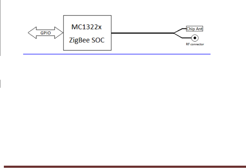
2.1 Block Diagram
Fig. 1 WZ401F-DVT
The GPIO interface of the module is specified in Sec.2.3 below.
On-board chip antenna or off-board antenna can be selected when manufacture. If off-board
antenna is used, chip antenna will not be mounted, and vice versa.
2.2 Requirements
2.2.1 RF Requirements (3.3V at 25°C)
Transmit power will be configured through firmware to 3dBm (typical)

© Copy Right 2012, LITE-ON Technology and Thinkeco Inc. Page 5
Receiver sensitivity -94 dBm (typical at 1% PER for 20 byte packets) (for RD SKU)
o LITEON suggest RX sensitivity to be -94dBm, the reason as below:
o -96dBm is the criterion for MC13224;
o WZ401F (normal range) add a connector;
o Trace is changed because we have to consider the shielding case;
Outdoor line of sight range 300m (1% PER for 20 byte packets) (for RD SKU)
Ceramic antenna shall be matched for return loss better 10dB over 2.4…2.5(for RD SKU)
LITEON shall characterize the module radiation pattern in the 3 orthogonal planes XY, XZ and YZ.
(for RD SKU)
See additional MC1322x RF specifications in Appendix 8.2
2.2.2 Reference crystal requirements
* See MC1322x specification in Appendix 8.1
2.2.3 Regulatory Compliance
* FCC Part 15.247 module certification
* CE (Optional)
* IC
2.2.4 Environmental
* Operating Temperature: -40°C to +85°C
* Humidity: 15% to 80% non-condensing
* RoHS
* WEEE
2.3 External Connections
UART1 (RTS, CTS, RX, TX)
UART2 (RX, TX)
I2C (SDA, SCL)
SPI (SCK, MISO, MOSI, SS)
TMR (TMR0, TMR1, TMR2, TMR3)
KBI (KBI0, KBI1, …, KBI7)
ADC2_VREFH, ADC2_VREFL
© Copy Right 2012, LITE-ON Technology and Thinkeco Inc. Page 6
RESETB
Power (VCC, GND)
JTAG (TDO, TDI, TCK, TMS, RTCK)
ADC0, ADC4
With 4 connections for GND and 2 connections for VCC, this amounts to a total of 402 external
connections.
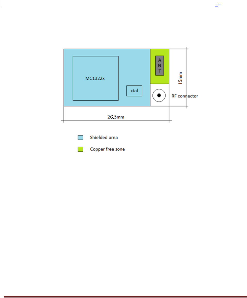
2.4 Mechanical
This figure illustrates the intended component layout and scale. The module needs to be
suitable for pick and place assembly.
3. Software
ThinkEco will be responsible for all software development and support.
Thinkeco will provide LITEON
Manufacturing testing and loading program
Manufacturing testing procedure

© Copy Right 2012, LITE-ON Technology and Thinkeco Inc. Page 7
Preliminary testing procedure reported in the document Simplified Test
ZigBee Modules v0.02 09-10-2012.pdf
© Copy Right 2012, LITE-ON Technology and Thinkeco Inc. Page 8
4. Manufacturing Testing Process
Conduct module tests
Collect and keep all logs for passed and failed units
Retest those failed units.
Send Thinkeco log files of passed or failed units for the first time, and log files of those unit
failed at the first time but passed at the 2nd time
Wait for Thinkeco’s log review and feedback
Receive Thinkeco’s approval to deliver the units to gateway production line.
5. Preproduction run
ThinkEco to receive and approve the detailed WI and quality process (by October 2012)
LITEON will do production trial run to validate process and allow ThinkEco to sign off (by
November 2012)
6. Packaging
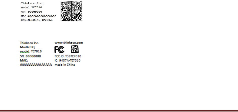
Labeling: Each product will be labeled based on Thinkeco specification
1) EVT units
2) Production units TE7010 with on-board antenna
3) Production units TE7010 with off-board antenna

© Copy Right 2012, LITE-ON Technology and Thinkeco Inc. Page 9
Delivery packaging:
Each product will be stocked and delivered inside an ESD bag
Shipping box: TBD
E-file: Each shipment will be anticipated by the E-file reporting all the tracking information
requested by Thinkeco. The e-file will be sent via email.
7. Appendix
8.1 Crystal Spec
See included file ZigBee Module - Excerpt MC1322x Data Sheet - Crystal Spec.pdf
8.2 RF Electrical Characteristics
See included file ZigBee Module - Excerpt MC1322x Data Sheet - RF Electrical Characteristics.pdf
8.3 RF Electrical Interface See
See included file ZigBee Module - Excerpt MC1322x Reference Manual - RF Interface.pdf
8.4 Documentation
MC1322x Data Sheet included in MC1322x.pdf
MC1322x Reference Manual included in MC1322xRM.pdf
8. FCC statement & Labels
Class B: (Section 15.105)
FEDERAL COMMUNICATIONS COMMISSION INTERFERENCE STATEMENT
This equipment has been tested and found to comply with the limits for a Class B digital device,
pursuant to part 15 of the FCC Rules. These limits are designed to provide reasonable protection
against harmful interference in a residential installation. This equipment generates, uses and can

© Copy Right 2012, LITE-ON Technology and Thinkeco Inc. Page 10
radiate radio frequency energy and, if not installed and used in accordance with the instructions,
may cause harmful interference to radio communications. However, there is no guarantee that
interference will not occur in a particular installation. If this equipment does cause harmful
interference to radio or television reception, which can be determined by turning the equipment off
and on, the user is encouraged to try to correct the interference by one or more of the following
measures:
-Reorient or relocate the receiving antenna.
-Increase the separation between the equipment and receiver.
-Connect the equipment into an outlet on a circuit different from that to which the receiver is
connected.
-Consult the dealer or an experienced radio/ TV technician for help.
CAUTION: (Section 15.21)
Any changes or modifications not expressly approved by the grantee of this device could void the
user's authority to operate the equipment.
Labeling requirements
This device complies with Part 15 of the FCC Rules. Operation is subject to the following two conditions:
(1) this device may not cause harmful interference, and (2) this device must accept any interference
received, including interference that may cause undesired operation.
RF exposure warning
This equipment must be installed and operated in accordance with provided instructions and the
antenna(s) used for this transmitter must be installed to provide a separation distance of at least
20 cm from all persons and must not be co-located or operating in conjunction with any other
antenna or transmitter. End-users and installers must be provide with antenna installation
instructions and transmitter operating conditions for satisfying RF exposure compliance.
© Copy Right 2012, LITE-ON Technology and Thinkeco Inc. Page 11
End Product Labeling
This transmitter module is authorized only for use in device where the antenna may be installed
such that 20cm may be maintained between the antenna and users. The final end product must
be labeled in a visible area with the following: "Contains FCC ID: Y38TE7010” and "Contains IC:
9407A-TE7010
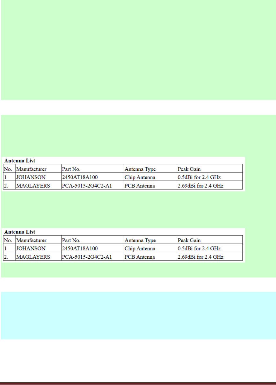
This radio transmitter FCC ID: Y38TE7010” has been approved by FCC to operate with the antenna
types listed below with the maximum permissible gain and required antenna impedance for each
antenna type indicated. Antenna types not included in this list, having a gain greater than the maximum
gain indicated for that type, are strictly prohibited for use with this device.
This radio transmitter IC: 9407A-TE7010 has been approved by Industry Canada to operate with the antenna
types listed below with the maximum permissible gain and required antenna impedance for each antenna
type indicated. Antenna types not included in this list, having a gain greater than the maximum gain
indicated for that type, are strictly prohibited for use with this device.
Canada, Industry Canada (IC) Notices
This Class B digital apparatus complies with Canadian ICES-003 and RSS-210.
Operation is subject to the following two conditions: (1) this device may not cause interference,
and (2) this device must accept any interference, including interference that may cause undesired
operation of the device.

© Copy Right 2012, LITE-ON Technology and Thinkeco Inc. Page 12
Radio Frequency (RF) Exposure Information
The radiated output power of the Wireless Device is below the Industry Canada (IC) radio frequency
exposure limits. The Wireless Device should be used in such a manner such that the potential for
human contact during normal operation is minimized.
This device has also been evaluated and shown compliant with the IC RF Exposure limits under
mobile exposure conditions. (antennas are greater than 20cm from a person's body).
Canada, avis d'Industry Canada (IC)
Cet appareil numérique de classe B est conforme aux normes canadiennes ICES-003 et RSS-210.
Son fonctionnement est soumis aux deux conditions suivantes : (1) cet appareil ne doit pas causer
d'interférence et (2) cet appareil doit accepter toute interférence, notamment les interférences qui
peuvent affecter son fonctionnement.
Informations concernant l'exposition aux fréquences radio (RF)
La puissance de sortie émise par l’appareil de sans fil est inférieure à la limite d'exposition aux
fréquences radio d'Industry Canada (IC). Utilisez l’appareil de sans fil de façon à minimiser les
contacts humains lors du fonctionnement normal.
Ce périphérique a également été évalué et démontré conforme aux limites d'exposition aux RF d'IC
dans des conditions d'exposition à des appareils mobiles (les antennes se situent à moins de 20 cm du
corps d'une personne).
Under Industry Canada regulations, this radio transmitter may only operate using an antenna of
a type and maximum (or lesser) gain approved for the transmitter by Industry Canada. To reduce
potential radio interference to other users, the antenna type and its gain should be so chosen that
the equivalent isotropically radiated power (e.i.r.p.) is not more than that necessary for successful
communication.