Thomas and Betts NEXUSAC Nexus Area Controller and Aexus Area Controller Router User Manual
Thomas & Betts Corporation Nexus Area Controller and Aexus Area Controller Router
User Manual
FIRST DRAFT
Thomas & Betts Tel: (888) 552-6467 ext. 547 or 255 Fax: (888) 867-1565 www.tnb.com 07/2010 750.1509 Rev A
1/31
Wireless Nexus Option
Area Controller & Router
OWNERS’S MANUAL
NOTE TO INSTALLER
This manual must be turned over to owner on completion of installation.
1. Installer
This manual must be turned over to owner on completion of installation.
1.1 Placing the Area Controller in the controller holder
• Install the controller holder to a wall with the attached screw.
• Placing the Area Controller on the controller holder
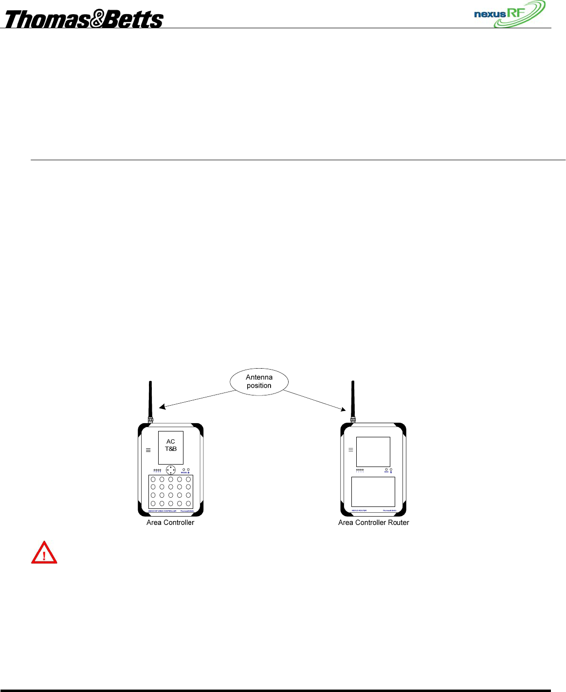
1.2 Antenna installation
• Install the antenna on the AC (Area Controller) See Install
• Turn the AC power OFF. All electrical installations should be performed by qualified personnel. The
antenna supplied with this equipment must be installed as shown below in Figure 1.
Important : the mating torque of the antenna must be 8 inch-pounds minimum and must not exceed a
maximum of 10 inch-pounds.
Figure 1
WARNING
This device complies with Part 15 of the FCC Rules. Operation is subject to the following conditions:
(1) this device may not cause harmful interference.
(2) this device must accept any interference received, including interference that may cause undesired operation.
(3) the user must installs the ferrites supplied by the manufacturer. See example in Figure 2 (Ferrite installation
details for the AC and ACR)
(4) only the supplied antenna must be installed in this equipment. See section “Unauthorized Antenna
Modifications” at next page.
FIRST DRAFT
Thomas & Betts Tel: (888) 552-6467 ext. 547 or 255 Fax: (888) 867-1565 www.tnb.com 07/2010 750.1509 Rev A
2/31
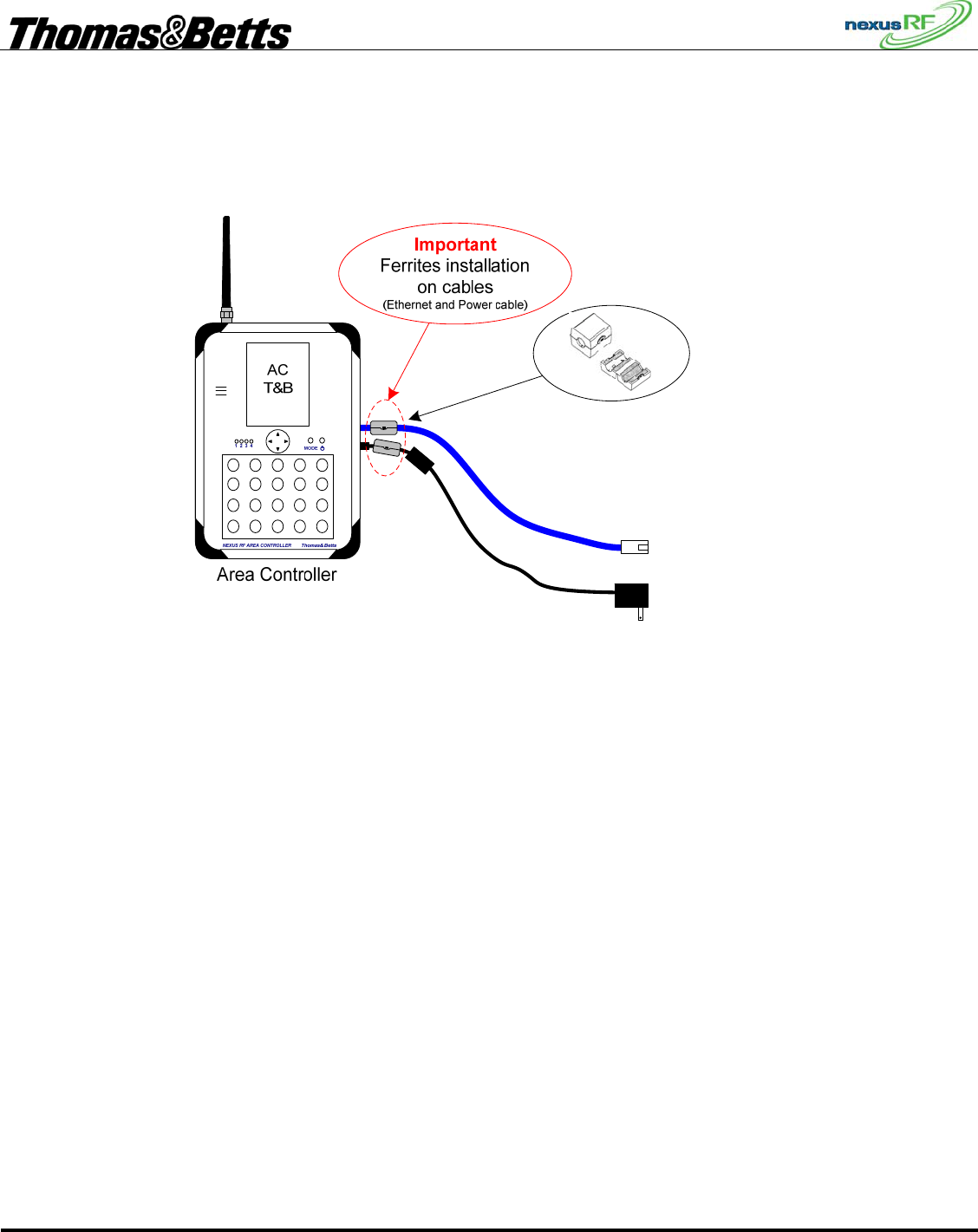
1.3 Cabling installation
• Install all cables, Ethernet for LAN, Power adaptor, …
• Install the two Ferrites include with this package on the Power supply cable and on the Ethernet cable. See
Figure 2 (Ferrite installation details for the AC and ACR)
Figure 2 (Ferrite installation details for the AC and ACR)
FIRST DRAFT
Thomas & Betts Tel: (888) 552-6467 ext. 547 or 255 Fax: (888) 867-1565 www.tnb.com 07/2010 750.1509 Rev A
3/31
2. INSTRUCTION TO THE USER
2.1 FCC Statement
This device complies with part 15 of the FCC rules.
FCC ID: W3BNEXUSAC
This equipment has been tested and found to comply with the limits for a Class B digital device, pursuant to Part
15 of the FCC rules. These limits are designed to provide reasonable protection against harmful interference in a
residential installation. This equipment generates, uses, and can radiate radio frequency energy and, if not
installed and used in accordance with the instructions, may cause harmful interference to radio communications.
However, there is no guarantee that interference will not occur in a particular installation. If this equipment does
cause harmful interference to radio or television reception, which can be determined by turning the equipment off
and on, the user is encouraged to try to correct the interference by one or more of the following measures:
• Reorient or relocate the receiving antenna.
• Increase the separation between the equipment and receiver.
• Connect the equipment to an outlet on a circuit different from that to which the receiver is connected.
• Consult the dealer or an experienced radio/TV technician for help.
IMPORTANT! Changes or modifications not covered in this addendum must be approved in writing by
the manufacturer’s Regulatory Engineering Department. Changes or modifications made without written approval
may void the user’s authority to operate this equipment.
2.2 Industry Canada
The term “IC:” before the certification/registration number only signifies that the Industry Canada technical
specifications were met.
IC: 8100A- NEXUSAC
Canadian Wireless Regulatory
This Class B digital apparatus meets all the requirements of the Canadian Interference Causing Equipment
Regulations. Operation is subject to the following two conditions: a) this device may not cause any interference,
and b) this device must accept any interference, including interference that may cause undesired operation of
the device. To prevent radio interference to the licensed service, this device is intended to be operated indoors,
and away from windows to prevent maximum shielding. Equipment (or its transmit antenna) that is installed
outdoors is subject to licensing.
Unauthorized Antenna Modifications
Use only the supplied integral antenna. Unauthorized antenna modifications or attachments could damage the
unit and may violate FCC regulations. Any changes or modifications not expressly approved by the party
responsible for compliance could void the user's authority to operate the equipment.
Precautions against electrostatic discharge (ESD)
Make sure to discharge any built-up static electricity from yourself and your electronic measurement devices
before touching this equipment. The recommendation from the dealer is that you take this precaution before
installation and connecting this equipment.

FIRST DRAFT
Thomas & Betts Tel: (888) 552-6467 ext. 547 or 255 Fax: (888) 867-1565 www.tnb.com 07/2010 750.1509 Rev A
4/31
3. Nexus Wireless system User Guide
3.1 Radio operations modes basic characteristics.
3.1.1 Mesh Network Mode (this is the normal mode of operation of the Wireless Nexus System)
• Lowest channel frequency: 918.6 MHz
• Highest channel frequency: 925.8 MHz
• Modulation Mode: GFSK
• Modulation frequency deviation: 19KHz
• Data Rate: 38 Kbits/s
• Maximum Output Power: -6.7 dBm
3.1.2 Backdoor Mode (used for close range communication for service purposes, using a mobile Area
Controller)
• Channel frequency: 918.0 MHz
• Modulation Mode: MSK
• Data Rate: 125 Kbits/s
• Maximum Output Power: -14.4 dBm
3.2 Introduction to Nexus RF
Nexus RF is a system that enables remote monitoring and testing of emergency lights using an RF mesh
network. There are 5 main components to the system:
• RF enabled emergency light units
• Area Controllers
• Area Controller Routers
• Area Controller IP backbone
• RF repeaters
The RF mesh network replaces the data cable that is connected to each of the emergency light units in a
conventional monitored system.
3.3 RF Mesh Network Operation
A “network” is the group of units controlled by an AC or ACR (referred to generically as Routers). The
Nexus RF protocol uses mesh networking to transfer messages between the Router and all units in the
network. This means that a particular RF unit does not need to be able to communicate directly with the
Router – the message is relayed automatically from one unit to the next to get to its final destination.
The number of hops a message must make is minimised automatically by the protocol.
When a Router is turned on it will attempt to form a network. Any units nearby that do not yet belong to
a network will discover the new network and attempt to join it. Other units that may not be in direct
range of the new Router will now be able to join this network through units that have joined it already. If
a unit loses contact with its current network, it will search all the available channel frequencies for a new
network and will attempt to join the first available network it finds.
Theoretically there can be up to 100 units in a network, but the practical maximum is determined by site
specific conditions. Generally speaking the larger the number of units in a network, the more restricted
is the data rate over the network.

FIRST DRAFT
Thomas & Betts Tel: (888) 552-6467 ext. 547 or 255 Fax: (888) 867-1565 www.tnb.com 07/2010 750.1509 Rev A
5/31
3.4 Nexus RF System Design Sequence
3.4.1 Plan the SPU Locations
The emergency lighting units in the Nexus RF system are positioned according to the requirements of
AS/NZ 2293 and are connected to the mains in the same way as conventional Single Point Units except
that there is no need to provide for a separate mains emergency lighting test switch.
Each Emergency unit is assigned a unique integer number called the SPU_ID. This number identifies the
location on the floor plan of the emergency unit. If the unit has to be replaced for some reason, the
SPU_ID should remain the same. In order to make the units easier to locate the SPU_ID is usually
assigned sequentially. If need be the SPU_ID is easily changed.
3.4.2 Plan the AC and ACR Locations
There should be at least one Area Controller and a number of Area Controller Routers for each domain.
The total number of Routers will depend on the number of units in the domain and the layout of the
building. A rule of thumb is a maximum of about 80 to 100 units for each Router. The smaller the
number of units in each RF channel, the faster the system response.
The Routers should be placed approximately in the centre of the group of units to be monitored so that
the hop count to each unit is minimised. The Area Controller would normally be placed in an area where
it can easily be accessed by maintenance staff as it is the primary user interface for the system. It is
possible to have multiple ACs in a domain if it is necessary to have multiple points of user interface.
3.4.3 Plan the Trunk Route
The Routers must all be connected to an IP backbone network. The preferred network type is an
Ethernet LAN using standard Cat-5 data cable. If there is an existing LAN available, then with the
permission of the network administrator, each of the Routers can be connected to spare ports on the
LAN. If there is no existing LAN, or the administrator will not allow the connection of the system, then
it will be necessary to install a dedicated LAN. If there are only 2 AC/ACR devices, then they can be
directly connected using a Cat-5 crossover cable. Alternatively, 2 or more devices can be connected
using an Ethernet hub or switch. In this case straight-through cables are used. Note that there is a limit of
about 100m for a run of Cat-5 cable. A longer distance will require the use of additional Ethernet hubs
or switches. The supply and installation of the Ethernet backbone is generally the responsibility of the
installing contractor. It is essential to ensure that the Cat-5 trunk cabling is installed in accordance with
the data cabling regulations. Refer to the installation section for the restrictions.
3.4.4 Mark up Drawings with Details
The as-built floor plan drawings should be updated with the SPU_ID, AC and ACR locations. In the
case of a dedicated LAN, the locations of the switches and the CAT-5 data cable runs should also be
marked.
FIRST DRAFT
Thomas & Betts Tel: (888) 552-6467 ext. 547 or 255 Fax: (888) 867-1565 www.tnb.com 07/2010 750.1509 Rev A
6/31
3.4.5 Example of an Ethernet backbone network
Ethernet
Rout12
AC
Ethernet
Rout7
ACR
Ethernet
Ethernet
Ethernet
Ethernet
Ethernet
S1
ETHERNET SWITCH
Ethernet
Rout2
ACR
Ethernet
Rout1
ACR
Ethernet
Rout3
ACR
Ethernet
Rout5
ACR
Ethernet
Rout4
ACR
Ethernet
Rout9
ACR
Ethernet
Rout6
ACR
Ethernet
Rout8
ACR
Ethernet
Ethernet
Ethernet
Ethernet
Ethernet
S2
ETHERNET SWITCH
Ethernet
Ethernet
Ethernet
Ethernet
Ethernet
S3
ETHERNET SWITCH
Ethernet
Rout10
ACR
Ethernet
Rout11
ACR
Ethernet
Ethernet
Ethernet
Ethernet
Ethernet
S4
ETHERNET SWITCH
Ethernet
PC1
PC
This diagram shows an example of a large Nexus RF system with an Ethernet LAN backbone. Each AC
or ACR is connected back to an Ethernet switch port by a length of Cat-5 data cable. In this case a PC is
shown connected to the LAN. This is optional and provides the user an alternative view of the system
via the web browser (Microsoft Internet Explorer) running on the PC.
Each Router (AC or ACR) controls its own network of RF units.
FIRST DRAFT
Thomas & Betts Tel: (888) 552-6467 ext. 547 or 255 Fax: (888) 867-1565 www.tnb.com 07/2010 750.1509 Rev A
7/31
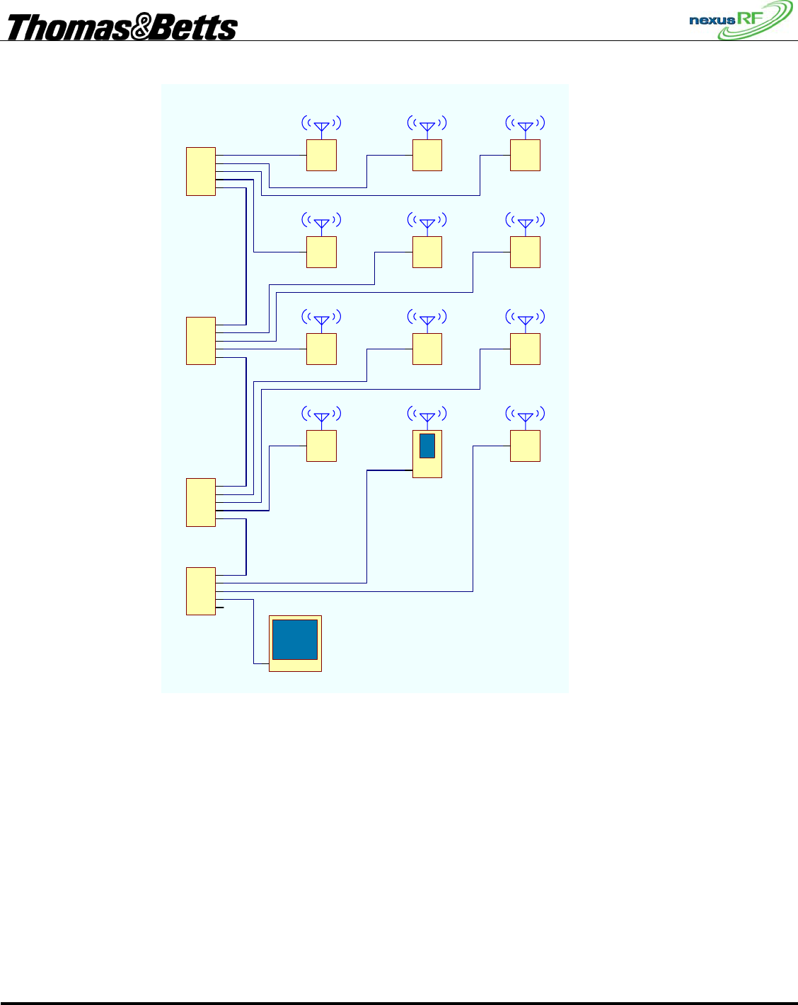
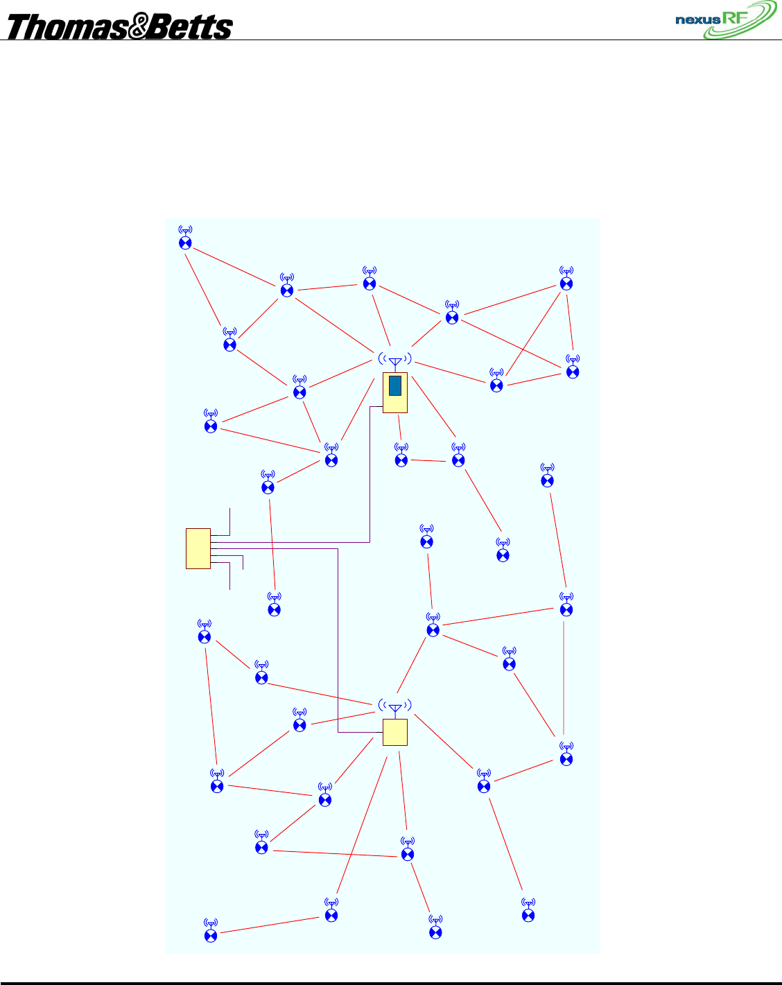
3.4.6 Example of an RF mesh network
This diagram shows an example of a part of a Nexus RF system. The AC and ACR each control one RF
network. The connections shown between the various SPUs represents the mesh network. Some units
have multiple connections to other units. Some units have direct connections to the Router.
Ethernet
AC
Ethernet
ACR
Ethernet
Ethernet
Ethernet
Ethernet
Ethernet
S4
ETHERNET SWITCH
FIRST DRAFT
Thomas & Betts Tel: (888) 552-6467 ext. 547 or 255 Fax: (888) 867-1565 www.tnb.com 07/2010 750.1509 Rev A
8/31
3.5 Area Controller Operation
3.5.1 AC Keypad Interface
The AC user interface can be operated using the keymat or using a USB keyboard or mouse. The
keymat is OK for occasional use but for extensive amounts of data entry – for instance during system
commissioning – a normal keyboard is more efficient.
There are basically 4 different types of screens: Menu (yellow), List (white), Data Display(red), Data
Edit (blue). They behave in characteristic ways.
Items in a screen are selected with the cursor buttons ▲ ▼ and accepted or rejected with ► or ◄.
Enter and Back on the keymat have similar functions to ► or ◄. If a USB keyboard is used, the cursor
buttons behave in the same way as cursor buttons on the keymat. If a USB mouse is connected, the black
cross pointer on the display becomes active and can be used to select items. Back and Next on the
bottom row of the display have the same function as Back and Enter on the keymat.
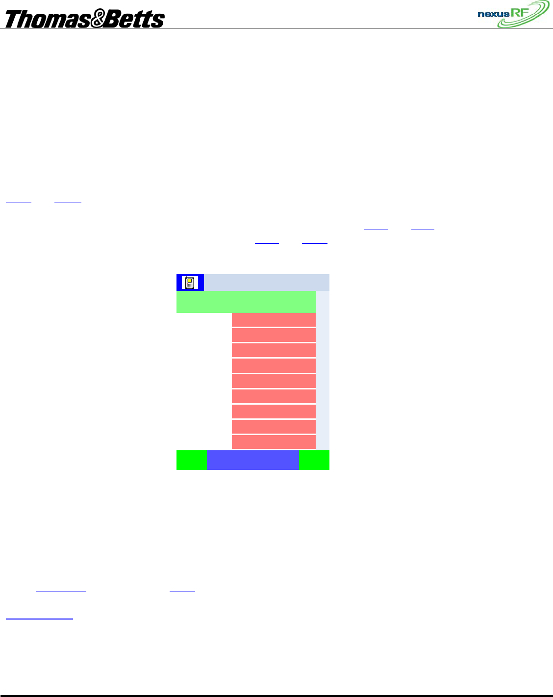
3.5.2 Status screen
1.16
Thu, 24-May-2007
0
7
3
0
100
4
180
Castletown
Back Next
Status
11:51:121
Total units
Units in maint
Online units
Total routers
Total groups
Grps under test
Date
Units under test
Version
When the AC is switched on and boots up, the Status screen is displayed. This is a summary of the
current system status.
The top row of the display shows the domain number (1) , domain name (Castletown) and the time.
The second row shows the name of the screen (Status).
Total units is the number of units that have been connected to all of the networks in the domain. If you
select Total units then press ► or Enter, the display will jump to the Units in Domain screen.
Units in maint is the total number of units in the Maintenance group. Select and Enter this to jump to the
Maintenance Group Menu.
Not all lines in a Data display screen will behave in this manner. The other items in this display will lead
to the Main Menu. Generally speaking, items in a Data Display window will lead to a Data edit screen
which enables the Data item to be edited.
FIRST DRAFT
Thomas & Betts Tel: (888) 552-6467 ext. 547 or 255 Fax: (888) 867-1565 www.tnb.com 07/2010 750.1509 Rev A
9/31
Online units is the number of units currently in communication with their respective channels in the
domain.
To go to the main menu press Back or ◄.
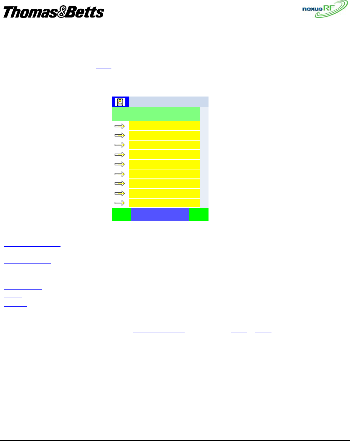
3.5.3 Main Menu screen
Help
Reports
Status
Search units
Emergency light testing
Commissioning
Tools
Routers in domain
Units in domain
Castletown
Back Next
Main Menu
11:51:121
The Main Menu: is a list of menu options:
Units in Domain – shows a List of units in the domain. The domain refers to the entire system.
Routers in Domain – shows a List of routers in the domain. Use this menu item to access channels.
Tools – shows a Menu of tools relevant to the whole system
Commissioning - shows a Menu of options for commissioning units and routers
Emergency Light Testing – shows a Menu of options relevant to grouping and testing the emergency
lights
Search Units - shows a Menu of options for locating or identifying specific units
Status – shows a Data Display of information relevant to the entire system
Reports – shows a menu of different report options for the system
Help – provides access to information about the software
To go to the Units in Domain screen select Units in Domain and press ►, Enter or Next.
FIRST DRAFT
Thomas & Betts Tel: (888) 552-6467 ext. 547 or 255 Fax: (888) 867-1565 www.tnb.com 07/2010 750.1509 Rev A
10/31
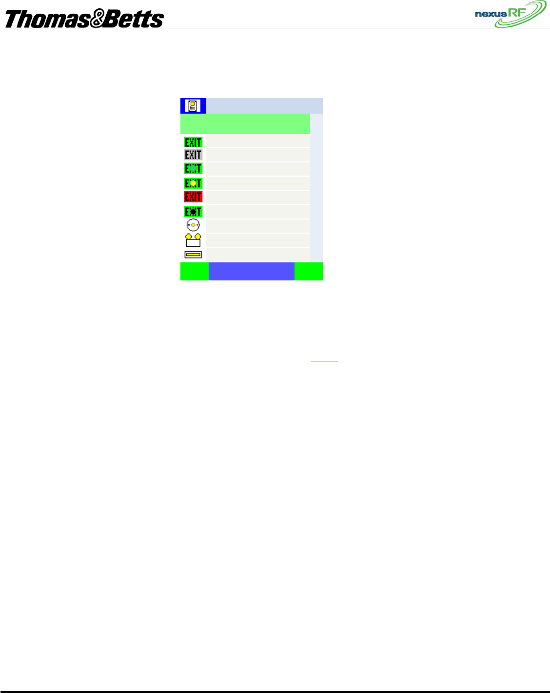
3.5.4 Units in Domain screen
9 OK
8 OK
7 OK
6 Test btn.
5 Fault
4 Yellow blink
3 Uncommissioned
2 Offline
1 OK
Castletown
Back NextSPUs
Units in Domain – 180 p 1 of 20
11:51:121
The Units in Domain screen shows a list of all units in the domain across multiple pages. The pages can
be accessed using the PAGE UP and PAGE DOWN buttons on the keypad. Each unit is represented by
an icon.
The units can be displayed in a variety of ways controlled by the Mode button:
• Icon, SPU_ID and status SPUs
• Icon, MAC address and status MACs
• Icon, SPU_ID, MAC address and status SPUm
• Icon, SPU_ID and location SPUl
• Icon, SPU_ID and Group SPUg
• Icon, Network address and status NETs
The Mode enunciator on the bottom line of the display shows which mode is selected – SPUs etc.
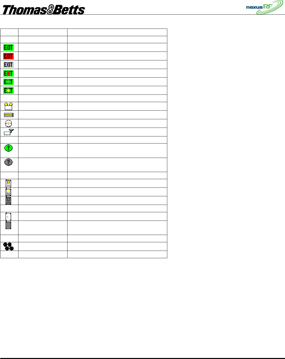
3.5.5 Unit Icon
The unit icon indicates the state of the unit. The table lists the alternative icons for one type of fitting –
the Quickfit and the plain icons for other fittings.
• The unit will indicate a fault if it detects a problem with its current state or it has failed its last
discharge test or diagnostic test.
• If the AC can no longer communicate with the unit the icon indicates the unit is offline. This
may be because of a comms problem or because of a more fundamental problem such as the unit
being disconnected from the mains.
• If the unit is under test the normal icon will have a red dot superimposed over it.
• If the unit is uncommissioned – ie does not yet have an SPU ID – it gets a green dot.
• It is useful sometimes to be able to identify one or more fittings by flashing the LED – when a
unit has been put in yellow blink mode it has a yellow dot over the icon.
• If a unit is part of the network but has not been identified as a particular type of fitting – it is
represented as an unknown.
FIRST DRAFT
Thomas & Betts Tel: (888) 552-6467 ext. 547 or 255 Fax: (888) 867-1565 www.tnb.com 07/2010 750.1509 Rev A
11/31
Icon Appearance Description
Plain icon Quickfit/Legend OK
Red icon Quickfit/Legend fault
Grey icon Quickfit/Legend no communications
Red dot Quickfit/Legend under test
Green dot Quickfit/Legend not commissioned
Yellow dot Quickfit/Legend yellow flashing LED
Plain icon Flood
Plain icon Batten
Plain icon Spitfire
Plain icon Repeater
? green
background
Unit unconfigured – type unknown
? grey
background
Unit unconfigured – type unknown
and no communications
Plain icon Area Controller
Plain icon Area Controller (remote)
Grey icon Area Controller no communications
Plain icon Area Controller Router
Grey icon Area Controller Router no
communications
Group
3.6 Unit Address
Each node has several different types of address:
3.6.1 MAC address
The MAC address is a unique 48-bit number that is programmed permanently into the unit in the
factory. The MAC address is displayed in hex format with leading zeroes eg: 00.00.10.b6. The full stops
act as place markers to make the number easier to read.

FIRST DRAFT
Thomas & Betts Tel: (888) 552-6467 ext. 547 or 255 Fax: (888) 867-1565 www.tnb.com 07/2010 750.1509 Rev A
12/31
3.6.2 Network Address
The network address consists of 4 numbers in sequence: the Domain ID-Router ID-Slot ID-Node ID.
When a unit joins a network it is supplied a network address by the Router controlling that network.
This address is not fixed for an RF network as a unit may move automatically from one network to
another as RF conditions on the site change.
3.6.3 SPU_ID
When a unit is commissioned it is given an SPU_ID by the installer which is unique in that domain.
Prior to being commissioned the SPU_ID of a unit is zero. The list of units is always sorted first by
SPU_ID then by MAC so that a list of uncommissioned units is sorted by MAC address.
3.6.4 Group Address
The group address is the means of collecting units together for scheduled emergency lighting testing. It
consists of a group number and group name. Once nodes are commissioned they can be grouped
arbitrarily across the domain by the user.
3.7 Network Setup
3.7.1 Set Up the Router Addresses
Each Router comes from the factory preset with a unique set of addresses. These are printed on a label
on the front of the ACR and on the right hand side of the AC.
Name – this is usually the serial number of the Router but it can be changed to another string.
Router ID – this is a unique number applied to the AC or ACR in production. It can be changed to a
another number as long as it is unique in the domain. Make sure that the main AC has the lowest Router
ID since the Router with the lowest ID is the master time clock.
IP Address and Net mask – each Router is supplied with a fixed IP address which will work without
change on a dedicated IP backbone. If the general purpose LAN in the building is to be used it will be
necessary for the IT system administrator to supply the appropriate fixed IP addresses.
For the Routers to be able to communicate over the backbone, they must each have a list of the address
details of the others.
First view the current setup of the AC: Power up all the Routers and connect them to the Ethernet
network using the RJ-45 ports. The AC boots up then displays the Status screen. Press Back or ◄ to
move to the Main Menu. From the Main Menu select Commissioning-Routers-Set my Router ID. This
screen shows all the address details of the AC. The Domain ID should be 1 (default), System ID 1000
(default) and the remaining items should match the label on the unit. There is no need to change any of
the items on this screen unless the unit is being set up with specific IP address for an existing LAN. To
back out without making changes, press Back. To accept changes press Next or Enter.
Now populate the Router table: From the Main Menu select Routers in Domain. This will display a list
of Routers in the Router table – there may only be one listed at this stage – the AC itself. From the Main
Menu select Commissioning-Routers-Add Router to Domain. Enter the address details (listed on the
label on the front) of the first Router – to accept changes press Next or Enter or press Back to exit
without changes. Go to the Routers in Domain screen - the display will show the Routers in Domain
screen and the Router just entered should appear on that screen. If the Router is actually connected to the

FIRST DRAFT
Thomas & Betts Tel: (888) 552-6467 ext. 547 or 255 Fax: (888) 867-1565 www.tnb.com 07/2010 750.1509 Rev A
13/31
Ethernet LAN it will show a lit up icon (perhaps after a minute or so in some cases), otherwise it will
show as greyed out. Enter the address details of all the other Routers in the same way.
At the end of this process the AC will have a list of all the other Routers in its Router table. Check the
Routers in Domain page again to confirm this. Once the LAN is connected to all these Routers they will
each build their own version of the table and each Router will be able to communicate with all other
Routers connected to the backbone.
3.7.2 Assign channels to the Routers
Each Router has 3 slots for interface cards – each of which can be assigned to a separate channel. Slot 1
(on the top of the unit) is usually used for the RF controller. (Future versions of the system will have the
ability to have other types of channel such as data cable). For instance, a system with 1 AC and 3
ACRs, each with one RF interface card in slot 1, should have 4 channels registered. The channel address
is made up of the Router number and the slot number. So this system with say Routers 27, 38, 52 and 20
will have channels 27-1, 38-1, 52-1 and 20-1. For the sake of neatness it is possible to re-number the
Routers to say 1, 2, 3 and 4 so that the channels would be 1-1, 2-1, 3-1, 4-1.
To see if the channels have been registered go to Routers in Domain, check within each Router listed for
its channel(s). To add a channel to a Router select Commissioning-Routers-Add Channel to Router from
the main menu. Enter the Router ID and Slot ID for each required channel in turn then check in
Channels to see if they are all listed correctly. If the Ethernet trunk is working correctly and the Routers
are powered up, connected to the backbone and correctly addressed, then each channel should be shown
as a lit up router icon. Any channels listed but not communicating will show as greyed out. Note that
when you back out of the Channel Menu the Channels in Domain screen is displayed which shows all
the channels in all the routers in the domain.
3.7.3 Set the Date and Time
Each Router has its own battery backed real time clock. These clocks automatically synchronise across
the backbone network to the time and date set in the Router with the lowest Router ID. The data and
time for an AC can be set from the local screen. If this AC has the lowest Router ID, that time will be
propagated across the network to all the other Routers. The data and time for a Router can also be set via
the internal web server from a remote PC.

FIRST DRAFT
Thomas & Betts Tel: (888) 552-6467 ext. 547 or 255 Fax: (888) 867-1565 www.tnb.com 07/2010 750.1509 Rev A
14/31
3.7.4 RF Network Formation – System ID
If the Routers are connected and set up correctly, they will each attempt to start a network and then any
RF emergency units installed and powered up in the vicinity will attempt to join a network. Note that
each channel in the system corresponds to a network. There is one more condition for network formation
– the emergency units must be pre-programmed with a System ID which matches the system ID of the
channel. By default all RF units are shipped with the same system ID – 1000. They will only join a
network started by a Router channel with a matching System ID. The System ID provides a mechanism
for two systems to sit side by side and yet stay separate. This may be required when for instance a tenant
in a shopping centre wants a separate system to the one run by the centre management.
Emergency units are shipped from the factory with SPU_ID = 0. A unit with SPU_ID = 0 is
uncommissioned. Commissioning is the process of assigning a non-zero SPU_ID to a unit. When the
Routers are operational and the emergency units powered up the RF networks will form automatically.
No further intervention is required from the operator until the time comes to enter the final SPU_IDs and
location data. To view all the units that have joined networks in the domain select Units in Domain from
the Main Menu. Note that if the Routers are switched off then on again the RF networks will completely
reform. This may take some time but it does not affect the system in any way other than delaying
activity.

FIRST DRAFT
Thomas & Betts Tel: (888) 552-6467 ext. 547 or 255 Fax: (888) 867-1565 www.tnb.com 07/2010 750.1509 Rev A
15/31
3.8 Commissioning
When a unit has SPU_ID = 0 it is uncommissioned. Once the unit joins a network it can be assigned an
SPU_ID. The SPU_ID is the link between the physical location of a unit and its hardware MAC address.
The SPU_ID must be marked by the installing contractor on the floor plan or on the ceiling or wall
adjacent to the unit.
The key to commissioning is to ensure that each unit in the Nexus database is assigned the correct
SPU_ID.
There are 2 distinct methods of commissioning:
3.8.1 Network commissioning
Each unit shipped from the factory has a label attached showing the MAC address of the unit. When the
unit is installed, the contractor records this number either on the floor plan that has the SPU_IDs marked
or on a sheet of paper that has the location and SPU_ID of each fitting listed.
From the Main Menu select Commissioning-Units over network. All of the units in the domain will be
listed. Using the Mode button select the display with MAC addresses. The node list is always sorted first
by SPU_ID then by MAC address so that a list of uncommissioned units (with SPU_ID zero) will be
displayed in order of MAC address. Either select the first MAC address in the list or move down the list
and select the node with the MAC address you want. The AC will suggest the next unused integer for
SPU_ID. The AC will also send a command to this unit to commence yellow blinking – the LED on the
fitting will flash yellow. The unit icon in the top left hand corner of the display will change to the yellow
blink state when the unit confirms that it has received the yellow blink message. Either accept the
suggested SPU_ID with Enter or change the number to the correct SPU_ID then Enter. Confirm the
selection by pressing Enter again. The AC will send out the commissioning message and display a
message to that effect. If the unit responds correctly the AC will indicate that the unit has been
commissioned. The icon in the top corner should change to the commissioned state to confirm that the
unit has received the new SPU_ID.
Alternatively, from the Main Menu select Commissioning-Units over network. Again all of the units in
the domain will be listed. Press the test switch on the unit to be commissioned – the AC will hide all
other units in the list and display only the unit selected by pressing the test switch. Press Enter and the
AC will suggest the next unused integer for SPU_ID. Either accept this or enter another number. This
method can really only be used for units near the AC or when there are two operators – one to operate
the AC and the other to operate the test switch on the units. In this situation the AC is not truly mobile
because the traffic is flowing through the mesh network. If the AC is moved under these circumstances
the network will have to re-build itself around the AC continuously. This will actually work but it may
be a little slow.

FIRST DRAFT
Thomas & Betts Tel: (888) 552-6467 ext. 547 or 255 Fax: (888) 867-1565 www.tnb.com 07/2010 750.1509 Rev A
16/31
3.8.2 Mobile commissioning
The mobile commissioning method does not use the network – instead it uses a low power direct RF link
between a mobile AC and the unit to be commissioned. From the Main Menu select Commissioning-
Units mobile. The AC will display a list of all units within direct (low power) radio range. This list is
sorted by SPU_ID in the normal manner so that any uncommissioned units in the list will appear at the
top. Press the test switch on the unit to be commissioned – if it is one of the units listed, the AC will hide
the others. Press Enter and the AC will suggest the next unused integer for SPU_ID and put that unit into
yellow blink mode. Enter the correct SPU_ID and the unit is now commissioned. The AC display will
return to the list of all units within radio range. If you cannot reach the test switch then choose one of the
units in the list – one that has a description that matches the unit in question – and select it. The AC will
suggest the next unused integer for SPU_ID and put that unit into yellow blink mode. If the unit in
question is also the one that starts yellow blinking then set the SPU_ID in the usual manner. If the LED
can’t be sighted then use the shortcut FUNC-1 (press FUNC then 1 in sequence) to put the unit into
emergency mode for a short period to aid in identifying the unit. If the unit identified is not the correct
one, press Back and choose another from the list.
3.9 Emergency Lighting Testing
3.9.1 Emergency Lighting Test
According to CSA / UL regulations, an emergency unit installed in a building must be tested every 1 month, 6 months
and year. See
Table 1 below
3.9.2 Group Names
The group is the addressing mechanism to enable scheduled testing of emergency units. Groups are
created as required by the user. Groups have a group number and a group name. When a unit first joins
the network, it is automatically added to a group with group number 0 and group name Group 0. To see
a list of all the groups created select Emergency Lighting Testing – List Groups from the Main Menu.
To add a group select Add Group from the Emergency Lighting Testing menu. The AC will suggest a
group number and name – edit these as required and press Enter or Next to accept. To rename a group,
select from the list of groups, then select Rename Group from the Group Menu. Edit the details as
required.
Table 1
Canadian CSA
(minutes)
American UL
(minutes)
Monthly test 1 1
6th month test 10 30
12th month test 30 90

FIRST DRAFT
Thomas & Betts Tel: (888) 552-6467 ext. 547 or 255 Fax: (888) 867-1565 www.tnb.com 07/2010 750.1509 Rev A
17/31
3.9.3 Using Groups
Groups are listed in the Groups in Domain screen with their number and name. If the group is currently
in test then that status is also shown.
To put units into a group select Emergency Lighting Testing – List Groups from the Main Menu, select
the desired group from the list and press Add online units to this group. A list of all the nodes in the
domain will appear.
To change the group for a particular fitting from the Unit Menu select Unit Tools – Group tools –
Change Group and enter the group number of the new group.
3.9.4 Scheduling Emergency Lighting Tests
Select the group to be tested from the Groups in Domain Menu then select Schedule Group Discharge
Test. The current settings are displayed – press ► to edit the details and Next or Enter to accept the
changes. The schedule consists of a start date and time together with and a test start window. The test
start window is the time allowed for the test to get underway. If communications are poor there may be a
delay between the test start command being sent to the fittings and the test commands being received by
the fittings. In order to prevent a test being commenced too long after the intended start time (and
thereby perhaps inconveniencing the building occupants), the test start window can limit the start time
delay. If the test command couldn’t be sent in time then the units affected will be placed automatically
in the Retest group.
The default initial values for the test schedule are:
Date: current date
Time: current time
Test start window: 60 mins
When the test start commands are sent out to the units in the group two additional parameters are added:
Set limit and Pass limit. The set limit is the maximum time the test for a particular unit can run before it
times out. The pass limit is the statutory time limit that the test must run for: 120mins for a node with a
battery in its first 6 months of life and 60 / 90 mins thereafter (CSA / UL). These values are determined
individually for each unit by the AC.
3.9.5 Retest Group
The Retest group is a virtual group used to collect all units that require re-testing for some reason or
because they failed to carry out their last scheduled test. The Retest group is scheduled in the same way
as a normal test group. Units are automatically placed in the group if a scheduled test is not carried out.
They are automatically removed from the Retest group if the test is completed (whether test passed or
failed). Units can also be manually placed in the Retest group and manually removed.

FIRST DRAFT
Thomas & Betts Tel: (888) 552-6467 ext. 547 or 255 Fax: (888) 867-1565 www.tnb.com 07/2010 750.1509 Rev A
18/31
3.9.6 Maintenance Group
The Maintenance group is a virtual group used to collect all units that either have a static fault or have
failed their last diagnostic test or discharge test. Faulty fittings are placed automatically in this group –
and are removed automatically when the faults are cleared. If a fitting has failed a previous discharge
test, and the problem that caused the failure has been addressed, then the unit should be retested. It
would be wasteful to retest the whole group because a few units failed so the unit is placed manually in
the Retest group. To do this select Emergency – Light – Testing – Maintenance Group – Place in Retest
Group to display the list of units in the group. Select in turn any units that you want to place in the
Retest group using ▼ and ► or Enter. Note that the Maintenance Group list can be accessed directly
from the Status screen. Select Units in Maint then press ► or Enter.
3.10 Reports
There are a number of reports that can be generated relating to the status, testing and maintenance of the
emergency lighting system. Each of the reports is generated in simple text format and downloaded onto
a USB flash stick. Note that the flash memory should be formatted for the FAT32 file system.
File names for the reports are suggested by the AC eg: /reports/070521TR0UD.txt – this file was created on 7th May 2007, a
Test Result report for all Units in Domain. If another report was generated straight afterwards it would have an updated
numerical index ie: /reports/070521TR1UD.txt The file names suggested by the AC for the reports can be edited by the user.
To view or print the reports plug the USB flash stick into a PC and open the files with any text editor. The results can be put
into a tabular format by opening in a spreadsheet application (eg Excel) and parsing using “comma” as the text delimiter.
3.10.1 Test Result report
From The Main Menu select Reports – Test result then select between:
• latest test result for all units in domain
• latest test result for all units in a specified group
• all test results for an individual unit
Insert a USB flash memory stick in the USB port and follow the prompts. The AC will create a file in a
folder called “reports “.
The test result report includes a site summary showing:
number of emergency units in the domain
number of units with a current discharge test pass
number of units with 6 monthly discharge test due
number of units with discharge test fail
The test result for each SPU selected is in the format:
test date
test time
test result – pass, fail, invalid.
discharge duration – time in minutes that unit was able to run in emergency test mode
set limit – time in units that unit would be allowed to test for until interrupted by timeout –
test stop cause – battery voltage under threshold, lamp current under threshold, relay did not operate,
aborted by user or timeout.

FIRST DRAFT
Thomas & Betts Tel: (888) 552-6467 ext. 547 or 255 Fax: (888) 867-1565 www.tnb.com 07/2010 750.1509 Rev A
19/31
3.10.2 Work Instruction Report
The work instruction report includes all units in the maintenance group.
For each unit the report includes:
the date of entry into the maintenance group and the fault status on entry
the last 3 discharge or diagnostic test results
the current status – either OK or faulty. If the status is faulty then a list of each individual fault detected
is displayed – including the bit number of the fault.
unit, lamp and battery ages – the age in years of each of the items. The “unit” refers to the Printed
Circuit Assembly. The age is calculated from the date of manufacture or from the date of replacement in
the maintenance log for that unit. Note that it is the responsibility of the maintenance contractor to
correctly enter the maintenance history data.
suggested maintenance actions:
check emergency lamp - this is suggested if the unit terminates a test due to lamp current limit before the
required time limit. Note that a unit without a functioning emergency lamp will terminate a test
immediately and register a discharge time of zero.
check mains lamp – this is suggested if the LDR indicates low light from the mains powered lamp when
the SA line is active.
check SA wiring to unit – this is suggested if the unit indicates the mains lamp powered from the SA line
is lit while the SA sense indicates the SA line is off.
check battery – this is suggested if the battery is not charging or the unit terminates a test due to battery
voltage limit before the required time limit
check test switch – this is suggested if the test switch on the emergency unit has been operated
continuously for more than 10 minutes.
check LDR – this is suggested if the LDR indicates low light from the mains powered lamp when the SA
line is active or if the LDR indicates light from the mains powered lamp when the SA line is not. In the
first instance the LDR could possibly be fitted to the wrong lamp or could itself be faulty. In the second
instance the LDR could be fitted to the wrong lamp or be responding to excessive amounts of stray light.
check unit – this is suggested if the fault is unknown.
check comms – this is suggested if there is no communications with the unit. It is possible that
communications to an RF node can come and go as the units attempts to join the strongest network.
Persistent lack of communications suggests that the unit is either un-powered or in need of a better RF
signal path. The antenna may not be connected correctly, or it may be pointed in the wrong direction.
Alternatively the unit may be too far from the nearest network and requires an RF repeater to boost the
RF signal.
FIRST DRAFT
Thomas & Betts Tel: (888) 552-6467 ext. 547 or 255 Fax: (888) 867-1565 www.tnb.com 07/2010 750.1509 Rev A
20/31
re-test unit – this is suggested if the unit has failed a test without the battery having been fully charged
prior to the test.
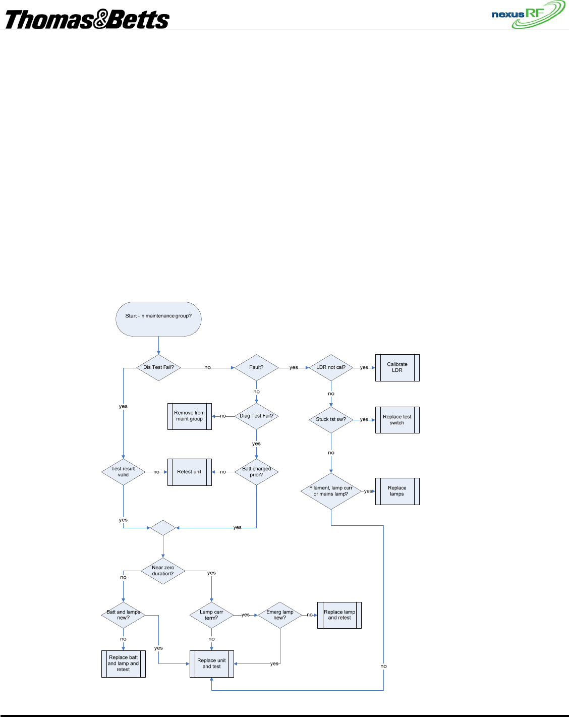
3.10.3 Basic Work Instruction report
The basic work instruction report includes all units in the maintenance group. The report is intended as
a guide to estimating the amount of replacement product required to bring a site up to standard. For each
unit there will be one or more suggested actions:
• Calibrate LDR
• Replace test switch
• Replace lamps
• Retest
• Replace lamp and retest
• Replace battery and lamp and retest
• Replace unit and test
The flow chart below describes the process the AC uses to determine the results:

FIRST DRAFT
Thomas & Betts Tel: (888) 552-6467 ext. 547 or 255 Fax: (888) 867-1565 www.tnb.com 07/2010 750.1509 Rev A
21/31
3.10.4 Offline report
Units which are offline are not included in the maintenance group. A unit is shown as offline if it is
unpowered or not communicating. The offline report list all offline units and includes the unit type and
data and time each unit was last online. If a unit is powered it may be offline due to a hardware fault or
because the RF communications are poor due to site conditions or poor antenna placement. A healthy
unit sends out a packet to the AC every minute. The AC records the date and time of this packet. An
offline unit may require replacement or antenna adjustment.
3.10.5 Maintenance History report
Select report for:
• all maintenance actions within the last 12 months for all units in domain
• all maintenance actions within the last 12 months for all units in a specified group
• all maintenance actions for an individual unit
The Maintenance History report includes a site summary showing:
number of emergency units in the domain
number of units with a current discharge test pass
number of units with 6 monthly discharge test due
number of units with discharge test fail
number of units with annual cleaning requirement fail
Each maintenance action is listed together with date and time of entry into the system.
Note that it is the responsibility of the maintenance contractor to enter maintenance actions as they are
carried out.
Possible maintenance actions are:
Replaced emergency lamp
Replaced mains lamp
Replaced battery
Replaced test switch
Replaced LDR
Replaced unit
Checked comms
Re-tested unit
Cleaned Unit
Other
3.10.6 Status report
The Status report is used to select units that exhibit a particular combination of faults or other
characteristics.
The possible selection criteria are:
Unit type: M,S,B,F,R
Unit part number:
Fault bit_1 or Fault bit_2 ... or Fault bit_32
Unit age between A,B
Lamp age between A,B
Battery age between A,B

FIRST DRAFT
Thomas & Betts Tel: (888) 552-6467 ext. 547 or 255 Fax: (888) 867-1565 www.tnb.com 07/2010 750.1509 Rev A
22/31
All units which satisfy all criteria specified are selected for the report.
For each unit selected the following information is printed:
Unit identification
Reason for being in and time spent in maintenance group
Last test result
Fault status
Age of unit, lamp and battery
3.10.7 Location report
The location report includes all the units in the database. For each unit the report lists all the available
location information as well as lamp, battery and unit age.
This report is used to help in locating units and also to check if all relevant location data has been
entered into the database.
3.10.8 Connection report
The connection report includes all devices in the database. The report is used to analyse the
communication connection topology of the network. For each unit the report lists:
SPU_ID:<SPU_ID>
Unit Type:
Group:
Unit Description:
Unit Part Number:
Location:
MAC address:
Firmware id: <sys-net-app>
Hop count to ACR:
Leaf node:
RF channel:
Rx packets:
Tx packets:
Unit load:
Up time:
On line time:
System ID:
Neighbour list:<neighbour SPU, neighbour MAC, neighbour RSSI>
3.11 Nexus RF Network Management
The mesh network consists of RF links between individual units. Only links with relatively strong signal
strengths are considered to be viable by the protocol. These links are referred to as Direct links.
To determine the RF performance of a single unit select Unit RF status from the Unit Menu. The AC
displays the System ID of the unit and the time since the unit last communicated with the AC. Every

FIRST DRAFT
Thomas & Betts Tel: (888) 552-6467 ext. 547 or 255 Fax: (888) 867-1565 www.tnb.com 07/2010 750.1509 Rev A
23/31
minute, a unit sends out a status packet to the AC so the Last seen value is usually less than 60 seconds.
If the unit is offline, the Last seen value will indicate how long the unit has been offline.
The Direct links screen lists all the units that this unit has a direct connection to. For each unit it lists the
RF signal strength received from the remote unit. This value is expressed in dBm. -45dBm is a very
strong signal while -100dBm is a very weak signal. This screen may take some time to return useful
values as the data is slow to extract. The AC requests that the unit report back on all the messages it sees
in a 5 second period – the request is repeated every 20 seconds.
The RSSI screen lists all the units that the unit in question can see – this is usually a longer list with
lower signal strengths.
Often the signal strength is not a good indicator of the quality of a link because it does not take account
of signal distortion due to reflections. The protocol handles this by looking at the reliability of a link
rather than just its signal strength – which in any case is a widely varying quantity.
The Info screen shows the packet related data. Hop cnt is the number of hops a message must take to
reach the Router from the unit in question. A hop count of 1 shows the unit has a direct link to the
Router.
Load is the amount of network traffic going through the unit – 20% is considered to be maximum
capacity.
Up time is the amount of time the unit has been running since last powered up.
The RF units have ample RF transmit power and receive sensitivity for the distances which separate
emergency lights in a building. However, a building is a complex RF environment with reflecting
surfaces, attenuating materials and external noise sources. The RF environment can be very dynamic and
can be strongly dependant on the time of day.
Once a site is fully installed it will be apparent which units communicate well and which do not. Areas
with poor links back to the Router may require the addition of RF repeaters. These are RF units identical
the RF emergency fittings but without any lighting functionality. The best method is to mark out the RF
performance of the network on a floor plan and determine if any RF repeaters are required. Sometime it
may be useful to change the location of Routers or add additional Routers to keep the average hop count
of units in each network low. Hop counts should be kept below 5 or 6 if possible. A network with large
hop counts and large numbers of units will be slow.
Channels which are side by side will slowly transfer units backwards and forwards between them in an
attempt to keep the network loads balanced.
3.12 Maintenance History
Maintenance actions carried out on each unit should be recorded in the database. This is a requirement
of the emergency Lighting Standard ???? which is called up by the Building code.
The date and time of entry of the maintenance actions are recorded. Specific actions can be checked off
as appropriate from the list.
Maintenance actions:
Replaced sustained lamp
Replaced maintained lamp
Replaced emergency lamp
Replaced battery
Replaced diffuser
Replaced unit

FIRST DRAFT
Thomas & Betts Tel: (888) 552-6467 ext. 547 or 255 Fax: (888) 867-1565 www.tnb.com 07/2010 750.1509 Rev A
24/31
Cleaned unit
Repaired wiring
Reconnected unit
If maintenance actions other than those listed are carried out they can be entered in the maintenance
notes field.
The lighting standard requires that emergency units be cleaned at least once a year. This should be in
general the only maintenance item for the bulk of units during their lifetime. To avoid having to enter
this maintenance item for each unit individually it is possible to enter it globally for all units.
3.13 Area Controller Firmware Update
To check the version of the AC firmware select Help-About or Status from the Main Menu. From time
to time it will be necessary to update the AC firmware. From Main Menu select Tools-Firmware
upgrade – Upgrade AC firmware. The unit will prompt you to insert a USB Flash Memory stick
containing the latest revision. Press Enter and the unit will reboot itself and propagate the new software
to all the other routers on the backbone network.
3.14 Emergency Light Units - SPUs
3.14.1 Configuration
A unit that is not configured has no information about its own identity. For instance an unconfigured
Quickfit does not know it is a Quickfit. This information is normally stored in a unit during production
testing. If for some reason a fitting has either no unit type or the wrong unit type then re-enter it. Select
Unit details from the Unit menu for the unit in question, highlight Unit Type and press Enter. Choose
from the Unit Type list:
• Batten
• Flood
• Quickfit/Legend
• Repeater
• Spitfire
If necessary change the unit sub-type as well in the same way. Choose from the Unit Sub-type list:
• Any
• Maintained
• Non maintained
• Sustained
• Twin maintained
Fittings with LDRs have their LDRs calibrated in the factory. If a unit has an LDR and is reconfigured
in the field then it will require re-calibration of the LDR. Note that a fitting in this state is placed in the
maintenance group.

FIRST DRAFT
Thomas & Betts Tel: (888) 552-6467 ext. 547 or 255 Fax: (888) 867-1565 www.tnb.com 07/2010 750.1509 Rev A
25/31
3.14.2 SPU Status
If there are no detectable faults with a unit it will return a status of OK in the Units list. If it is testing,
has the test switch operated, is in yellow blink mode or is uncommissioned but is otherwise OK it will
return one of those states as its status. If the unit has a fault or has failed its last test it will return a status
of Fault.
To see in greater detail the type of fault, select Unit status. This page lists all the known faults as well as
the date and time when the unit was placed in the maintenance group as a result of being faulty.
List of possible status bits:
Bit
number
State
0 Button is stuck
1 Relay is stuck
2 Filament failure
3 Unspecified HW fault
4 No lamp current
5 Battery is discharged
6 Battery is not charging
7 Mains lamp is not working
8 Emergency tube is too dim
9 Inverter is erroneously off
10 Inverter is erroneously on
11 Lamp current when there
shouldn't be
12 Mains lamp is too dim
13 SA off and mains lamp on
14 LDR not calibrated
15 Repeater's buzzer is on
21 Mains lamp is off
22 Mains lamp is on
23 Last test failed
24 Fault status
25 Fitting is OK
26 Not charged for 16 hours
27 Button is pressed
28 Test is running
29 Yellow LED is on (or blinking)
30 Unit is not commissioned
31 Unit is not configured

FIRST DRAFT
Thomas & Betts Tel: (888) 552-6467 ext. 547 or 255 Fax: (888) 867-1565 www.tnb.com 07/2010 750.1509 Rev A
26/31
3.14.3 Data stored in Node:
The following data is stored in each unit:
Address data (SPU_ID, System_ID, MAC address, network_ID, node_ID);
Group_ID (current and default);
Configuration data (T&B part number, unit type);
Location data;
Test result data (7 sets);
Last fault date (1);
Unit mfg/change date for unit, lamp and battery;
Discharge test set time.
This is a subset of the information about each fitting stored in the main AC database and is enough
information to usefully re-construct the database in the event of its loss.
3.14.4 SPU LED Colour Meanings
The LED on a fitting will flash according to its status. The table below describes the various states. The
states are prioritised – a state with high priority will take precedence over a state with low priority. For
instance if a unit is under test – and therefore showing a red slow flash – is put into yellow blink at the
same time, the LED will show the yellow link pattern since it has a higher priority.
Priority Index LED pattern
description State
1 13,14,15 yellow flash - one long
six short Configured and in flash yellow mode for
identification
2 0 green very slow flash Unconfigured
3 11 red slow flash Configured, not in yellow flash and
emergency test running
4 12 green on steady OK and button pressed
4 1,2,3,4,5,6 green flash with one red
blink Configured but
emergency hardware fault
5 7 green flash with two red
blinks Configured and hardware OK but
unit uncommissioned and
no RF network connection
5 8 green flash with three red
blinks Configured and hardware OK and
RF network connection OK but
unit uncommissioned
5 9 alternating green/red
flash Configured, commissioned and hardware
OK but
no RF network connection
5 10 red on steady OK

FIRST DRAFT
Thomas & Betts Tel: (888) 552-6467 ext. 547 or 255 Fax: (888) 867-1565 www.tnb.com 07/2010 750.1509 Rev A
27/31
3.14.5 Menu Tree
Units in domain
<unit list>
Unit status
Unit RF status
Direct links
RSSI
Info
Unit location
Unit details
Unit test
Diagnostic test
Scheduled test
Previous test
Unit maintenance
List unit maintenance
Add unit maintenance record
Unit tools
Commission unit
Group tools
Change group
Return to Default group
Set current group as default group
Yellow blink on
Yellow blink off
Set SPUID
Reset unit
Calibrate LDR
Upload firmware
Routers in domain
<router list>
Units in router
<unit list>
(Unit Menu)
Channels in Router
<channel list>
Units in channel
Channel status
Channel tools
Set RF channel number
Stop channel operation
Start channel operation
Channel yellow blink on
Channel yellow blink off
Channel RF status
Direct links
RSSI
Info
Tools
Delete tools
Delete unit
Delete by List
Delete by SPUID
Delete by MAC
Delete channel

FIRST DRAFT
Thomas & Betts Tel: (888) 552-6467 ext. 547 or 255 Fax: (888) 867-1565 www.tnb.com 07/2010 750.1509 Rev A
28/31
<channel list>
Delete Router
<router list>
Delete Domain
Domain yellow blink off
Change Domain name
Backup database
Load database
Set clock
Firmware upgrade
Upgrade AC firmware
Download ELN firmware to AC
Download EIM firmware to AC
Upload ELN firmware across network
Upload by List
Upload by SPUID
Upload by MAC
Upload ELN firmware directly
Upload EIM firmware to EIM
Production Testing
Commissioning
Units over network
<unit list>
Units mobile
Routers
Add router to domain
Add channel to router
Set my router ID
Emergency light testing
List groups
<group list>
Units in group
Group status
Group details
Schedule group discharge test
Perform group diagnostic test
Group yellow blink on
Group yellow blink off
Delete this group
Add units to group
<unit list>
Add group
Maintenance group
Units in group
Group status
Yellow blink on
Yellow blink off
Retest group
Units in group
Group status
Schedule group discharge test
Perform group diagnostic test
Yellow blink on
Yellow blink off
Add maintenance units to this group
Search units
By SPUID

FIRST DRAFT
Thomas & Betts Tel: (888) 552-6467 ext. 547 or 255 Fax: (888) 867-1565 www.tnb.com 07/2010 750.1509 Rev A
29/31
By MAC address
By pressing service button
Status
Reports
Test result
For units in domain
For units in group
For individual unit
Work instruction
Basic work instruction
Maintenance history
For units in domain – 12 mths
For units in group – 12 mths
For individual unit – all
Status
Unit type
Unit part number
Fault bit list
Unit age band
Lamp age band
Battery age band
Location
For units in domain
For units in group
For individual unit
Connection
Offline units
Help
About
3.15 Nexus RF Database
The Nexus database stores all the information pertaining to the system and the units. A copy of this
database is stored in each router in the domain. As the contents of the database changes, the system
ensures that each copy of the database is kept up to date. If a Router is disconnected from the backbone
for a period, when it is reconnected the system ensures that the most up-to-date information is copied to
all the other routers. The database can be backed up using a USB flash drive – the database files are
compressed into a single .tar file. To backup the database select Tools – Backup database from the Main
Menu. The AC will prompt to insert a USB flash. The AC will create a folder on the flash drive and load
the backup. To load a copy of the database select Tools – Load database and insert the USB flash drive.
The AC will display a list of files – each with a date code. Select the appropriate file.

FIRST DRAFT
Thomas & Betts Tel: (888) 552-6467 ext. 547 or 255 Fax: (888) 867-1565 www.tnb.com 07/2010 750.1509 Rev A
30/31
3.16 Glossary
AC Area Controller – has LCD and keyppad
AC mobile AC with internal rechargeable battery pack for mobile use
ACR Area Controller Router – same as AC but with no LCD or
keypad and without option of battery pack
Channel Corresponds to a slot in the AC or ACR. Each AC or ACR
Channel number
Commissioned
Configured
Default Group
Diagnostic Test
Domain
Domain ID
Firmware
Group
HW ID
MAC address
Maintenance Group A collection of all nodes in the domain with either a status
fault, discharge test failure, diagnostic test failure or
communications fault
Node ID
Part Desc
Part No
Retest Group
RFCH
Router ID
Scheduled Test
Slot ID
SPUID
Status
Status Code
Unit
Unit type
Yellow blink
Single Point Unit
RF_SPU
SA Switched Active
USA Un-switched Active
LDR Light Dependant Resistor used to sense the mains
powered lamp light output

FIRST DRAFT
Thomas & Betts Tel: (888) 552-6467 ext. 547 or 255 Fax: (888) 867-1565 www.tnb.com 07/2010 750.1509 Rev A
31/31
3.16.1 Menu Shortcuts
Func 1 Status
Func 2
Func 3
Func 4 Search Units
Func 5
Func 6
Func 7
Func 8
Func 9