Thomson 2-5110A 2.4GHz SIngle-Line FHSS, Cordless Telephone w/ CID User Manual 25110 indd
Thomson Inc. 2.4GHz SIngle-Line FHSS, Cordless Telephone w/ CID 25110 indd
Thomson >
USERS MANUAL

2.4 Ghz Cordless Telephone
and Wireless Headset with
Call-Waiting/Caller ID
User’s Guide
Please read this manual
before operating this
product for the first time.
Model 25110

2
Equipment Approval Information
Your telephone equipment is approved for connection to the Public Switched Telephone Network and is in compliance with parts 15 and 68,
FCC Rules and Regulations and the Technical Requirements for Telephone Terminal Equipment published by ACTA.
1 Notification to the Local Telephone Company
On the bottom of this equipment is a label indicating, among other information, the US number and Ringer Equivalence Number (REN) for the equipment.
You must, upon request, provide this information to your telephone company.
The REN is useful in determining the number of devices you may connect to your telephone line and still have all of these devices ring when your telephone
number is called. In most (but not all) areas, the sum of the RENs of all devices connected to one line should not exceed 5. To be certain of the number of
devices you may connect to your line as determined by the REN, you should contact your local telephone company.
A plug and jack used to connect this equipment to the premises wiring and telephone network must comply with the applicable FCC Part 68 rules and re-
quirements adopted by the ACTA. A compliant telephone cord and modular plug is provided with this product. It is designed to be connected to a compatible
modular jack that is also compliant. See installation instructions for details.
Notes
• This equipment may not be used on coin service provided by the telephone company.
• Party lines are subject to state tariffs, and therefore, you may not be able to use your own telephone equipment if you are on a party line. Check with your
local telephone company.
• Notice must be given to the telephone company upon permanent disconnection of your telephone from your line.
• If your home has specially wired alarm equipment connected to the telephone line, ensure the installation of this product does not disable your alarm
equipment. If you have questions about what will disable alarm equipment, consult your telephone company or a qualified installer.
2 Rights of the Telephone Company
Should your equipment cause trouble on your line which may harm the telephone network, the telephone company shall, where practicable, notify you
that temporary discontinuance of service may be required. Where prior notice is not practicable and the circumstances warrant such action, the telephone
company may temporarily discontinue service immediately. In case of such temporary discontinuance, the telephone company must: (1) promptly notify you
of such temporary discontinuance; (2) afford you the opportunity to correct the situation; and (3) inform you of your right to bring a complaint to the Com-
mission pursuant to procedures set forth in Subpart E of Part 68, FCC Rules and Regulations.
The telephone company may make changes in its communications facilities, equipment, operations or procedures where such action is required in the opera-
tion of its business and not inconsistent with FCC Rules and Regulations. If these changes are expected to affect the use or performance of your telephone
equipment, the telephone company must give you adequate notice, in writing, to allow you to maintain uninterrupted service.
Important Information

3
Interference Information
This device complies with Part 15 of the FCC Rules. Operation is subject to the following two conditions: (1) This device may not cause harmful interference;
and (2) This device must accept any interference received, including interference that may cause undesired operation.
This equipment has been tested and found to comply with the limits for a Class B digital device, pursuant to Part 15 of the FCC Rules. These limits are de-
signed to provide reasonable protection against harmful interference in a residential installation.
This equipment generates, uses, and can radiate radio frequency energy and, if not installed and used in accordance with the instructions, may cause harmful
interference to radio communications. However, there is no guarantee that interference will not occur in a particular installation.
If this equipment does cause harmful interference to radio or television reception, which can be determined by turning the equipment off and on, the user is
encouraged to try to correct the interference by one or more of the following measures:
• Reorient or relocate the receiving antenna (that is, the antenna for radio or television that is “receiving” the interference).
• Reorient or relocate and increase the separation between the telecommunications equipment and receiving antenna.
• Connect the telecommunications equipment into an outlet on a circuit different from that to which the receiving antenna is connected.
If these measures do not eliminate the interference, please consult your dealer or an experienced radio/television technician for additional suggestions. Also,
the Federal Communications Commission has prepared a helpful booklet, “How To Identify and Resolve Radio/TV Interference Problems.” This booklet is avail-
able from the U.S. Government Printing Office, Washington, D.C. 20402. Please specify stock number 004-000-00345-4 when ordering copies.
FCC RF Radiation Exposure Statement
This equipment complies with FCC RF radiation exposure limits set forth for an uncontrolled environment. This equipment should be
installed and operated with a minimum distance of 20 centimeters between the radiator and your body. This transmitter must not be
co-located or operated in conjunction with any other antenna or transmitter.”
For body worn operation, this phone has been tested and meets the FCC RF exposure guidelines when used with the belt clip supplied
with this product. Use of other accessories may not ensure compliance with FCC RF exposure guidelines.
Licensing
Licensed under US Patent 6,427,009.
Hearing Aid Compatibility
This telephone system meets FCC standards for Hearing Aid Compatibility.
US NUMBER IS LOCATED ON THE CABINET BOTTOM
REN NUMBER IS LOCATED ON THE CABINET BOTTOM
Important Information

4
Table of Contents
EQUIPMENT APPROVAL INFORMATION ..............................................................2
INTERFERENCE INFORMATION ..........................................................................3
FCC RF RADIATION EXPOSURE STATEMENT .....................................................3
LICENSING .................................................................................................3
HEARING AID COMPATIBILITY ........................................................................3
INTRODUCTION ............................................................................................6
PARTS CHECKLIST ........................................................................................7
IMPORTANT INSTALLATION INFORMATION ..........................................................8
SAFETY PRECAUTIONS .............................................................................................. 8
INSTALLATION GUIDELINES ........................................................................................ 8
TELEPHONE JACK REQUIREMENTS ....................................................................9
HEADSET SET UP .....................................................................................10
HEADBAND ATTACHMENT .......................................................................................10
To switch from ear to ear .................................................................................... 11
EAR CLIP ATTACHMENT .........................................................................................12
To switch from ear to ear ....................................................................................12
PHONE INSTALLATION ................................................................................ 13
CONNECTING THE AC (ELECTRICAL) POWER ...........................................................13
Charger unit ............................................................................................................13
Wall base unit .........................................................................................................13
CONNECTING THE TELEPHONE LINE .........................................................................13
INSTALLING THE BATTERIES .....................................................................................14
Installing the Handset Battery ..........................................................................14
Installing the Earpiece Battery ..........................................................................15
HANDSET LAYOUT .................................................................................... 16
HEADSET LAYOUT ..................................................................................... 17
HANDSET SET UP .................................................................................... 18
DISPLAY LANGUAGE ...............................................................................................18
TONE/PULSE DIALING ............................................................................................18
AREA CODE ..........................................................................................................18
RINGER TONE .......................................................................................................19
RINGER VOLUME ...................................................................................................19
DEFAULT SETTING SELECTION .................................................................................19
TELEPHONE OPERATION ............................................................................. 20
MAKING A CALL ...................................................................................................20
On the Handset ......................................................................................................20
On the Headset .......................................................................................................20
ANSWERING A CALL .............................................................................................20
On the Handset ......................................................................................................20
On the Headset .......................................................................................................20
CALL TRANSFER ....................................................................................................21
MUTE ...................................................................................................................21
REDIAL .................................................................................................................21
FLASH ..................................................................................................................22
EXIT .....................................................................................................................22
HANDSET VOLUME ................................................................................................22
HEADSET VOLUME .................................................................................................22
To Adjust Volume from Headset: ......................................................................22
To Adjust Volume from Handset: ......................................................................22
PAGING THE HANDSET AND HEADSET .....................................................................23
IN USE INDICATOR LIGHT ......................................................................................23
On the Handset ......................................................................................................23
On the Headset .......................................................................................................23
CHARGER INDICATOR LIGHT ...................................................................................23
CALL TIMER ..........................................................................................................24
TEMPORARY TONE DIALING ....................................................................................24

5
Table of Contents
CALLER ID ............................................................................................. 25
CALLER ID WITH CALL WAITING ............................................................................25
RECEIVING AND STORING CALLS .............................................................................25
REVIEWING RECORDS ............................................................................................25
TRANSFERRING CID RECORDS TO MEMORY ............................................................26
DELETING RECORDS ...............................................................................................26
DELETING THE CURRENT RECORD ...........................................................................26
DELETING ALL RECORDS ........................................................................................27
DIALING A CALLER ID NUMBER ............................................................................27
CHANGING THE CID NUMBER FORMAT ..................................................................27
MEMORY ............................................................................................... 28
STORING A NAME AND NUMBER IN MEMORY ........................................................28
VIEWING A STORED NUMBER .................................................................................29
CHANGING A STORED NUMBER ..............................................................................29
STORING A REDIAL NUMBER ..................................................................................29
DIALING A STORED NUMBER .................................................................................30
INSERTING A PAUSE IN THE DIALING SEQUENCE OF A STORED NUMBER ...................30
REVIEWING AND DELETING STORED NUMBERS ........................................................30
HEADSET AND BELT CLIP OPERATION ............................................................31
CONNECTING AN OPTIONAL HEADSET TO THE HANDSET ...........................................31
ATTACHING THE BELT CLIP .....................................................................................31
REPLACING THE BATTERIES ......................................................................... 32
HANDSET BATTERY ................................................................................................32
HANDSET MEMORY RETENTION ............................................................................32
HEADSET BATTERY .................................................................................................33
BATTERY SAFETY PRECAUTIONS ................................................................... 33
DISPLAY MESSAGES ................................................................................. 34
HANDSET SOUND SIGNALS ......................................................................... 35
CALLER ID ...........................................................................................................35
No display .................................................................................................................35
Caller ID error message ........................................................................................36
TELEPHONE ...........................................................................................................36
No dial tone .............................................................................................................36
TROUBLESHOOTING TIPS .........................................................37
GENERAL PRODUCT CARE .......................................................................... 38
CAUSES OF POOR RECEPTION ..................................................................... 38
INTERFERENCE INFORMATION ....................................................................... 39
SERVICE ................................................................................................. 40
LIMITED WARRANTY ..................................................................................41
6
Introduction
CAUTION: When using telephone equipment, there are basic safety instructions that
should always be followed. Refer to the IMPORTANT SAFETY INSTRUCTIONS provided
with this product and save them for future reference.
Your Caller ID phone stores and displays information provided by your local tele-
phone company, to subscribers of Caller ID or similar caller identification services.
Your Caller ID phone enables you to:
• Identify callers before you answer the phone.
• View the time and date of each incoming call.
• Record up to 99 Caller ID messages sequentially.
• Know who called while you were away.
To get the most from your new phone, we suggest that you take a few minutes
right now to read through this user’s guide.
IMPORTANT: In order to use all of the features of this unit, you must subscribe to either the
standard Name/Number Caller ID Service or Call Waiting Caller ID Service. To know who is
calling while you are on the phone, you must subscribe to Call Waiting Caller ID Service.
IMPORTANT: Because cordless phones operate on electricity, you should have at least one
phone in your home that isn’t cordless, in case the power in your home goes out.
Important Information
SEE MARKING ON BOTTOM / BACK OF PRODUCT
RISK OF ELECTRIC SHOCK
DO NOT OPEN
WARNING: TO
PREVENT FIRE OR
ELECTRICAL SHOCK
HAZARD, DO NOT
EXPOSE THIS
PRODUCT TO RAIN
OR MOISTURE.
THE LIGHTNING
FLASH AND ARROW
HEAD WITHIN THE
TRIANGLE IS A
WARNING SIGN
ALERTING YOU OF
“DANGEROUS
VOLTAGE” INSIDE
THE PRODUCT.
CAUTION: TO REDUCE THE
RISK OF ELECTRIC SHOCK, DO
NOT REMOVE COVER (OR
BACK). NO USER
SERVICEABLE PARTS INSIDE.
REFER SERVICING TO
QUALIFIED SERVICE
PERSONNEL.
THE EXCLAMATION
POINT WITHIN THE
TRIANGLE IS A
WARNING SIGN
ALERTING YOU OF
IMPORTANT
INSTRUCTIONS
ACCOMPANYING
THE PRODUCT.
CAUTION:
7
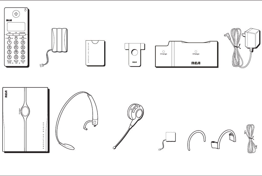
Parts Checklist
Make sure your package includes the following items:
Wall base
Handset Battery
compartment cover
Telephone
line cord
AC power
adaptor
Connections & Setup
ChargerHandset battery Belt clip
Headband Headset battery Ear clip ringEar clipHeadset

8
Important Installation Information
Safety Precautions
• Never install telephone wiring during a lightning storm.
• Never install telephone jacks in wet locations unless the jack is specifically
designed for wet locations.
• Never touch non-insulated telephone wires or terminals, unless the telephone
line is disconnected from the network.
• Use caution when installing or modifying telephone lines.
• Temporarily disconnect any equipment connected to the phone such as faxes,
other phones, or modems.
Installation Guidelines
• Install the wall base unit into an electrical outlet that is near a telephone
(modular) jack.
• Avoid sources of noise, such as a window by a busy street, and electrical noise,
such as motors, microwave ovens, and fluorescent lighting.
• Avoid heat sources, such as heating air ducts, heating appliances, radiators, and
direct sunlight.
• Avoid areas of excessive moisture or extremely low temperature.
• Avoid dusty locations.
• Avoid other cordless telephones or personal computers.
Connections & Setup

9
Modular telephone
line jack
Wall plate
Connections & Setup
CAUTION: Always disconnect all phone cords from the base unit before battery
installation or replacement.
INSTALLATION NOTE: Some cordless telephones operate at frequencies that may cause
or receive interference with TVs, microwave ovens, and VCRs. To minimize or prevent such
interference, the base of the cordless telephone should not be placed near or on top of a TV,
microwave ovens, or VCR. If such interference continues, move the cordless telephone farther
away from these appliances. Certain other communications devices may also use the 2.4GHz
frequency for communication, and, if not properly set, these devices may interfere with each
other and/or your new telephone. If you are concerned with interference, please refer to
the owner’s manual for these devices on how to properly set channels to avoid interference.
Typical devices that may use the 2.4GHz frequency for communication include wireless
audio/video senders, wireless computer networks, multi-handset cordless telephone systems,
and some long-range cordless telephone systems.
Telephone Jack Requirements
To use this phone, you will need an RJ11C type modular phone jack, which might
look like the one pictured here, installed in your home. If you don’t have a modular
jack, call your local phone company to find out how to get one installed.

10
Headset Set Up
Headband Attachment
1. Hold the headband and insert it into keyed slot marked with an arrow on the
headset.
NOTE: To ensure proper installation, the connector is keyed and can only be inserted one way
2. Rotate the L-shaped band 90 degrees clockwise.
3. Align the L-shaped band into the hole on the headset.
Connections & Setup
11
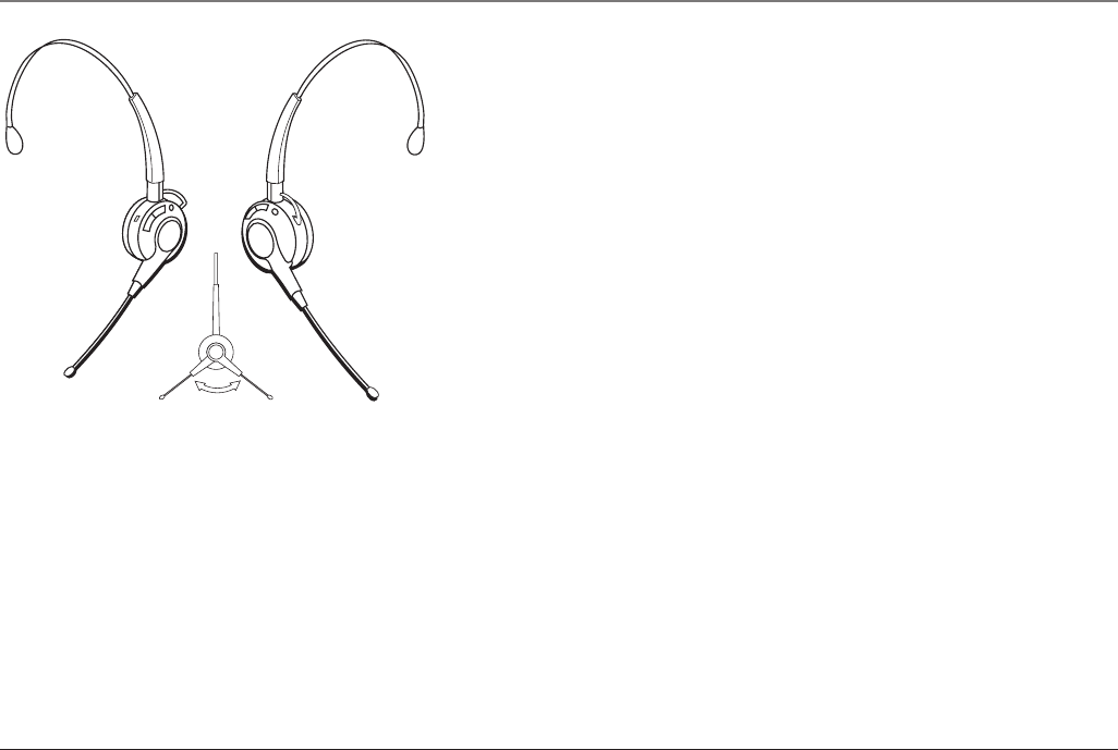
To switch from ear to ear
Rotate microphone boom to reposition nearer to mouth.
Connections & Setup

12
Ear Clip Attachment
1. Attach the ear clip ring to the headset and ensure all three contact points align
and are engaged.
2. Insert ear clip into either side of ear clip ring, matching with the “L” or “R”
marked on ear clip ring to fit either your left or right ear.
To switch from ear to ear
Unplug the ear clip from ear clip ring.
Insert the ear clip to ear clip ring with “L” mark for Left ear.
Insert the ear clip to “R” mark for Right ear.
Rotate microphone boom to reposition nearer to mouth.
Connections & Setup
13
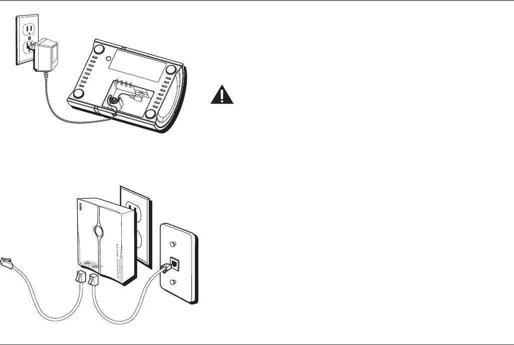
Phone Installation
Connecting the AC (Electrical) Power
Charger unit
Plug the AC power adaptor into an electrical outlet and the DC connector into the
bottom of the charger.
CAUTION: Only use the ATLINKS USA. Inc. 5-2678 power converter that came with this
unit. Using other power converters may damage the charger unit.
Wall base unit
To install your wall base unit, locate an electrical outlet with a phone jack nearby.
1. Plug the wall base unit into an electrical outlet.
2. Make sure that the pins are inserted fully and firmly into the outlet. If not,
choose another electrical outlet.
Connecting the Telephone Line
There are two jacks on the bottom of the wall base unit.
Plug one end of the telephone line cord into the LINE jack on the bottom of the
wall base unit and the other end into a modular jack.
The PHONE jack may be used to connect a parallel phone by connecting a second
telephone line cord from the PHONE jack on the bottom of the wall base unit to the
parallel phone.
Connections & Setup
14
Installing the Batteries
Installing the Handset Battery
NOTE: You must connect the handset battery before use.
1. Locate battery and battery door which are packaged together inside a plastic
bag and are separate from the handset.
2. Locate the battery compartment on the back of the handset.
3. Plug the battery pack cord into the jack inside the compartment.
NOTE: It is important to maintain the polarity (black and red wires) to the jack inside the
compartment. To ensure proper battery installation, the connector is keyed and can be
inserted only one way.
4. Insert the battery pack.
5. Close the battery compartment by pushing the door up until it snaps into place.
6. Place the handset in the charging cradle.
Allow the handset to charge for 16 hours prior to first use. If you don’t properly charge the
handset, battery performance is compromised.
CAUTION: To reduce the risk of fire or personal injury, only use the ATLINKS Ni-MH
battery model 5-2683.
BLACK WIRE
RED WIRE
BATTERY
PRESS DOWN
FIRMLY
Connections & Setup
15
Installing the Earpiece Battery
NOTE: You must connect the earpiece battery before use.
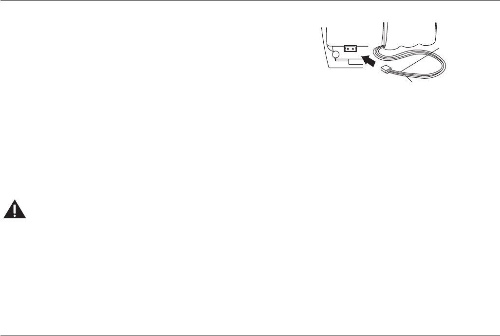
1. Locate the battery compartment inside the headset.
2. Plug the battery pack cord into the jack inside the compartment.
NOTE: It is important to maintain the polarity (black and red wires) to the jack inside the
compartment. To ensure proper battery installation, the connector is keyed and can be
inserted only one way.
4. Insert the battery pack.
5. Close the battery compartment by pushing the door up until it snaps into place.
6. Place the headset in the charging cradle.
Allow the headset to charge for 16 hours prior to first use. If you don’t properly charge the
headset, battery performance is compromised.
CAUTION: To reduce the risk of fire or personal injury, only use ATLINKS Li-polymer
battery model 5-2682.
Connections & Setup
16
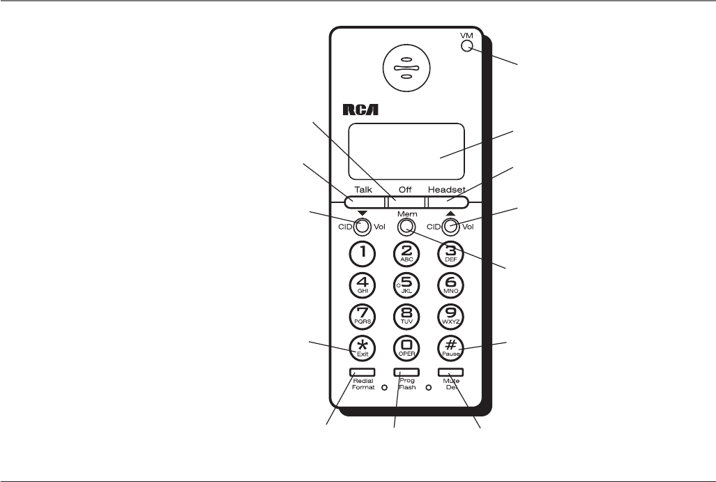
CID/Vol
(Caller ID/Volume
button)
Redial/Format
(button)
Talk
(button)
Prog/Flash
(program/flash
button)
*Exit
(button)
Mem
(memory button)
#Pause
(button)
display
Off
(button)
Handset Layout
Mute/Del
(mute/delete
button)
CID/Vol
(Caller ID/Volume
button)
Headset
(button)
VM
(visual message
waiting indicator)
Connections & Setup
17
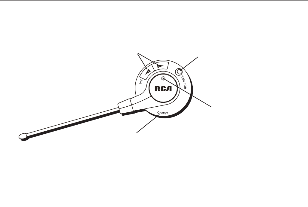
Vol or
(Volume button)
Charge
indicator
Talk/Off
(button)
Headset Layout
Connections & Setup
Charge
contact

18
Handset Set Up
There are six programmable menus available: Display Language, Tone/Pulse
Dialing Local Area Code, Ringer Tone, Ringer Volume and Factory Default.
When you program these settings, make sure the phone is OFF (not in talk mode).
Pressing the *Exit button will remove you from the menu selection process without
changing the feature you are in.
Display Language
1. Press the Prog/Flash button until 1ENG 2FRA 3ESP shows in the display.
2. Use the CID/Vol ( or ) buttons or the handset number pad to select
1.ENGLISH, 2.FRANCAIS, or 3.ESPANOL. The default setting is “1.ENGLISH”.
3. Press the Prog/Flash button to confirm. You will hear a confirmation tone.
Tone/Pulse Dialing
1. Press the Prog/Flash button until 1TONE 2PULSE shows in the display.
2. Use the CID/Vol ( or ) buttons or the handset number pad to select
(1) TONE or (2) PULSE. The default setting is “TONE”.
3. Press the Prog/Flash button to confirm. You will hear a confirmation tone.
Area Code
1. Press the Prog/Flash button until - - - SET AREA CODE shows in the display.
2. Use the handset touch-tone pad to enter your three digit area code. “- - -” is
the default setting.
4. Press the Prog/Flash button to confirm. You will hear a confirmation tone.
Connections & Setup

19
Ringer Tone
1. Press the Prog/Flash button until RINGER TONE 1 shows in the display.
2. Use the CID/Vol ( or ) buttons or the handset number pad to select
and listen to a ringer tone. There are seven ringer tones to choose from. The
default setting is “1”.
3. Press the Prog/Flash button to confirm. You will hear a confirmation tone.
Ringer Volume
1. Press the Prog/Flash button until RINGER VOL 1HI shows in the display.
2. Use the CID/Vol ( or ) buttons or the handset number pad to select 1 (HI),
2 (LOW), or 3 (OFF). The default setting is “1HI”.
3. Press the Prog/Flash button to confirm. You will hear a confirmation tone.
Default Setting Selection
1. Press the Prog/Flash button until DEFAULT SETTING shows in the display.
2. Use the CID/Vol ( or ) buttons or the handset number pad to select 1 (NO),
or 2 (YES). The default setting is “NO”. If you choose NO, the current settings
remain. If you choose YES, the unit resets to the factory default.
3. Press the Prog/Flash button to confirm.
Connections & Setup

20
Telephone Operation
Making a Call
On the Handset
1. Press the Talk button on the handset to get a dial tone.
2. When finished, press the Off button on the handset to hang up.
On the Headset
1. Press the Talk/Off button on the headset OR the Headset button on the handset
to get a dial tone.
2. When finished, press the Off button on the handset OR the Talk/Off button on
the headset to hang up.
Answering A Call
On the Handset
1. When the phone rings, pick up the handset and press the Talk button to answer
the call.
2. When finished, press Off button on the handset to hang up.
On the Headset
1. When the phone rings, pick up the headset and press the Talk/Off button OR
press the Headset button on the handset to answer the call.
2. When finished, press the Talk/Off button on the headset OR the Off button on
the handset to hang up.
Operation

21
Call Transfer
Durng a call this feature allows you to transfer the call back and forth from handset
to headset.
1. Press the Headset button on the handset or the Talk/Off button on the headset,
the call will then be transferred from handset to headset.
2. Press the Talk button on the handset, the call will then be transferred back from
headset to handset.
Mute
To have a private, off-line conversation use the mute feature. The party on the
telephone line will not hear you, but you can still hear them.
On the Handset or Headset
1. Press the Mute/Del button on the handset. MUTE ON will blink intermittently,
along with the call status, in the display on the handset.
2. Press the Mute/Del button again to cancel mute and return to your phone con-
versation.
Redial
When the phone is on (in TALK mode), press the Redial/Format button to redial the
last number you dialed (up to 32 digits). If you get a busy signal, and want to keep
dialing the number, just press Redial/Format again (you do not have to turn the
phone off and back on).
Operation

22
Flash
Use the Prog/Flash button to activate custom calling services such as call waiting or
call transfer, which are available through your local phone company.
TIP: Do not use the Talk button to activate custom calling services such as call waiting, or you
will hang up the phone.
Exit
Press the *Exit button to cancel any command you initiated.
Handset Volume
While talking, press the CID/Vol ( or ) buttons to adjust the listening level of
the handset’s earpiece. There are four volume levels. Press the button to increase
the volume level, and press the button to decrease. VOL 1 is the lowest level and
VOL 4 is the loudest.
Headset Volume
To Adjust Volume from Headset:
While talking, the headset receiver volume can be adjusted by pressing the Vol
( or ) buttons. The volume can be increased or decreased, step by step up to
4 levels. When maximum level or minimum level is reached, an error tone is emitted.
The last setting is kept when re-cradled. The headset volume level shows on the
handset LCD.
To Adjust Volume from Handset:
The headset receiver volume shall be adjusted by pressing the CID/Vol ( or )
buttons on handset. The volume is increased or decreased step by step up to 4 levels.
The volume level shows on handset. The last setting is kept when re-cradled.
Operation

23
Operation
Paging the Handset and Headset
Press the Page button on the wall base. The handset and headset will beep and the
in use indicators on both will flash for two minutes (or until page is terminated.)
To terminate page signal:
Press the Page button on the wall base.
OR
Press any button on the handset or headset.
NOTE: If there is an incoming call, the handset will automatically terminate the page signal
and play ring tone.
In Use Indicator Light
On the Handset
The handset in use indicator light is lit when the handset is on. It flashes when a call
is received, if there is a Message Waiting (VM) or if the Page button on wall base is
pressed.
On the Headset
The headset in use indicator light is lit when the headset is on. It flashes when a call
is received, if the Page button on the wall base is pressed, if you have a low battery
or are attempting to charge the unit without a battery.
Charger Indicator Light
The charge indicator light is lit when the handset or headset is charging in its cradle
on the charger.

24
Operation
Call Timer
The built-in call timer shows in the display and counts the call time in minutes and
seconds.
Temporary Tone Dialing
This feature is useful only if you use pulse dialing service. Temporary tone dialing
enables pulse (rotary) service phone users to access touch-tone services offered by
banks, credit card companies, etc. For example, when you call your bank you may
need to enter your account number. Using the temporary tone feature allows you to
temporarily switch to touch-tone mode so you can enter and send your number.
1. Press the Talk button, dial the telephone number (i.e. bank or credit card com-
pany), and wait for the line to connect.
2. When your call is answered, press the *Exit button on your handset number pad
to temporarily change from pulse dialing to tone dialing.
3. Follow the automated instructions to get the information you need.
4. Hang up the handset and the phone automatically returns to pulse (rotary)
dialing mode.

25
Caller ID
Caller ID
This unit receives and displays information transmitted by your local phone com-
pany. This information can include the phone number, date, and time; or the name,
phone number, date, and time. The unit can store up to 99 calls for later review.
Caller ID with Call Waiting
Provided you subscribe to Caller ID with Call Waiting service from your phone com-
pany, you are able to see who is calling when you hear the call waiting beep. The
caller identification information appears in the display after you hear the tone.
• Press the Prog/Flash button to put the current person on hold so that you can
answer the incoming call.
IMPORTANT: I
n order to use the Caller ID functions with this unit, you must subscribe to
either the standard Name/Number Caller ID Service or Call Waiting Caller ID Service. To know
who is calling while you are on the phone, you must subscribe to Call Waiting Caller ID Service.
Receiving and Storing Calls
When you receive a call, the information is transmitted by the phone company to
your Caller ID telephone between the first and second ring.
When the memory is full, a new call automatically replaces the oldest call in
memory. NEW appears in the display for calls received that have not been reviewed.
NOTE: Check with your local phone company regarding name service availability.
Reviewing Records
As calls are received and stored, the display is updated to let you know how many
calls have been received.
• Press the CID/Vol button to scroll through the call records from the most
recent to the oldest.
• Press the CID/Vol button to scroll through the call records from the oldest to
the newest.
NEW CALL #
Caller ID name
Caller ID phone number
Time Date New call

26
Caller ID
Transferring CID Records to Memory
You may transfer a Caller ID record to your phone’s memory.
NOTE: It is important that you format CID records correctly before storing in memory. It is not
possible to re-format CID records stored in memory.
1. Use the CID/Vol ( or ) buttons to scroll to the record.
2. Press the Mem button.
3. Press the memory location buttons. You will hear a confirmation tone. For ex-
ample, press the number 0 and 1 keys to store the record in memory location 01.
To replace a CID record stored in a memory location with a new CID record:
1. Repeat steps 1 through 3.
2. REPLACE MEMO? shows in the display.
3. Press the *Exit button to exit, or press Mem again and the new CID record re-
places the old CID record in that memory location. You will hear a confirmation
tone.
Deleting Records
Use the Mute/Del button to erase the record currently shown in the display or all
records.
Deleting the Current Record
1. Make sure the phone is OFF (not in TALK mode).
2. Use the CID/Vol ( or ) buttons to scroll to the Caller ID record you want to
delete.
3. Press Mute/Del button. The display shows DELETE?
4. Press Mute/Del again to erase the record. You will hear a confirmation tone. The
display shows DELETED. Then the next Caller ID record shows in the display.

27
Caller ID
Deleting All Records
1. Make sure the phone is OFF (not in TALK mode).
2. Use the CID/Vol ( or ) buttons to display any Caller ID record.
3. Press and hold the Mute/Del button until the unit beeps and DELETE ALL? shows
in the display.
4. Press Mute/Del again to erase all records. You will hear a confirmation tone, and
the display shows NO CALLS.
Dialing a Caller ID Number
1. Make sure the phone is OFF (not in TALK mode).
2. Use the CID/Vol ( or ) buttons to display the Caller ID record you want to
dial.
3. Press the Talk or Headset button on the handset. The number dials
automatically.
Changing the CID Number Format
The format button lets you change the format of the displayed CID number. The
available formats are as follows.
7-digit 7-digit telephone number.
10-digit 3-digit area code + 7-digit telephone number.
11-digit long distance code “1” + 3-digit area code + 7-digit telephone number.
1. Use the CID/Vol ( or ) buttons to scroll to the number you want to call
back.
2. If the number does not dial as shown, press the format button. Repeat if
necessary, until the correct number of digits show in the display.
3. Press the Talk or Headset button on the handset. The number
dials automatically.

28
Memory
Store up to 50 24-digit numbers in memory for quick dialing. This memory feature
is in addition to the 99 Caller ID records that can be stored in the Caller ID memory
log.
Storing a Name and Number in Memory
1. Make sure the phone is OFF (not in TALK mode).
2. Press the Mem button.
3. Press the memory location button (01 through 50 records).
4. Press the Mem button again. The display shows ENTER NAME (up to 15
characters).
NOTE: If you don’t want to enter the name, skip to step 5.
For example, to enter the name Bill Smith, press the two key twice for the letter
B, press the four key three times for the letter I, and press the five key three
times for the letter L. After one second, press the five key three times again for
the second letter L and press the one key to insert a space between the letter L
and S. Press the seven key four times for the letter S, press the six key once for
the letter M, press the four key three times for the letter I, press the eight key
once for the letter T, and press the four key twice for the letter H.
NOTE: If you make a mistake, press the del button to erase a wrong letter, and re-enter the
correct letter.
5. Press the Mem button to save the name. The display shows ENTER TEL NUMBR.
6. Use the handset touch-tone pad to enter the telephone number (up to 24 digits)
you want to store.
7. Press Mem again to store the number. You will hear a confirmation tone.
Memory

29
Viewing a Stored Number
When handset or headset is ON (in TALK mode), press the Mem button on the hand-
set and key in number 01 to 50 or use the CID/Vol ( or ) buttons to scroll to
the number you want to view.
Changing a Stored Number
1. Repeat steps 1 through 6 in Storing a Name and Number in Memory.
2. Press the Mem button and REPLACE MEMO? shows in the display.
3. Press the *Exit button to exit, or press the Mem button to store the number. You
will hear a confirmation tone.
Storing a Redial Number
1. Repeat steps 1 through 5 in Storing a Name and Number in Memory.
2. Press the Redial/Format button.
3. Press the Mem button to store the number. You will hear a confirmation tone.
To replace an old redial number stored in a memory locations with a new redial
number:
1. Repeat steps 1 through 5 in Storing a Name and Number in Memory.
2. Press the Redial/Format button.
3. Press the Mem button and REPLACE MEMO? shows in the display.
4. Press *Exit to exit, or press the mem button again and the new redial number
replaces the old redial number in that memory location. You will hear a confir-
mation tone.
Memory

30
Dialing a Stored Number
1. Make sure the handset or headset is ON (in TALK mode) by pressing the Talk or
Headset button on the handset or the Talk/Off button on the headset.
2. Press the Mem button.
3. Press the memory location button (01 through 50 records).
4. Press the Talk or Headset button on the handset. The number dials
automatically.
- OR -
1. Make sure the handset or headset is OFF (not in TALK mode).
2. Press Mem button.
3. Use the CID/Vol ( or ) buttons to scroll to the number you want to dial.
4. Press the Talk or Headset button on the handset. The number dials automati-
cally.
Inserting a Pause in the Dialing Sequence of a Stored Number
When a pause is needed to wait for a dial tone, press the #Pause button twice
within one second (for example, when you must dial 9 for an outside line or to wait
for a computer access tone.) A “pause” in the dialing sequence shows in the display
as a “P .” Each pause counts as 1 digit in the dialing sequence.
Reviewing and Deleting Stored Numbers
1. Press the Mem button.
2. Use the CID/Vol ( or ) buttons to scroll to the number.
3. To delete the number, press the Mute/Del button. The display shows DELETE?
Memory
31
4. Press Mute/Del again to delete the number. DELETED shows in the display.
Headset and Belt Clip Operation
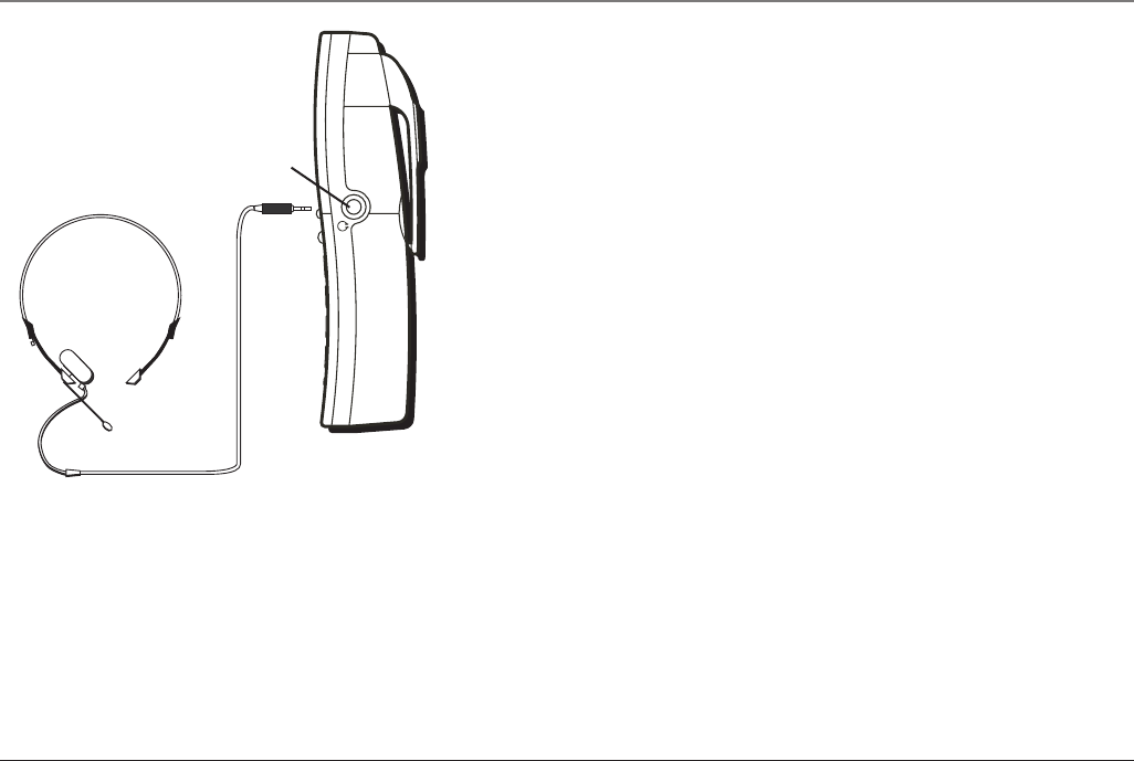
Connecting an Optional Headset to the Handset
1. Connect the headset (optional) to the HEADSET jack as shown. The handset
receiver and microphone are disabled when the headset is connected.
TIP: To order a headset, please refer to the accessory order form at the end of this user’s guide.
2. Adjust the headset to rest comfortably on top of your head and over your ear.
Move the microphone to approximately 2 to 3 inches from your mouth.
3. Press the Talk button to answer or place a call.
4. To return to normal operation, unplug the headset from the jack.
Attaching the Belt Clip
1. Insert the sides of the belt clip into the slots on each side of the handset.
Other Information
headset jack

32
BLACK WIRE
RED WIRE
BATTERY
PRESS DOWN
FIRMLY
2. Snap the ends of the belt clip into place.
Replacing the Batteries
Handset Battery
1. Make sure the telephone is OFF (not in TALK mode) before you replace battery.
2. Remove the battery compartment door.
3. Disconnect the cord attached to the battery pack from the jack inside the bat-
tery compartment and remove the battery pack.
4. Insert the new battery pack and connect the plug on the battery pack to the
jack inside the compartment.
NOTE: It is important to maintain the polarity (black and red wires) to the jack inside the
compartment. To ensure proper battery installation, the connector is keyed and can be
inserted only one way.
5. Close the battery compartment by pushing the door up until it snaps into place.
6. Place the handset in the charging cradle.
Allow the handset battery to properly charge (for 16 hours) prior to first use or when you
install a new battery pack. If you do not properly charge the phone, battery performance
will be compromised.
CAUTION: To reduce the risk of fire or personal injury, only use ATLINKS Ni-MH-battery
model 5-2683.
Handset Memory Retention
When battery is disconnected the handset has the capability to hold the user
Other Information
33
memory and Caller ID memory for up to 5 minutes.
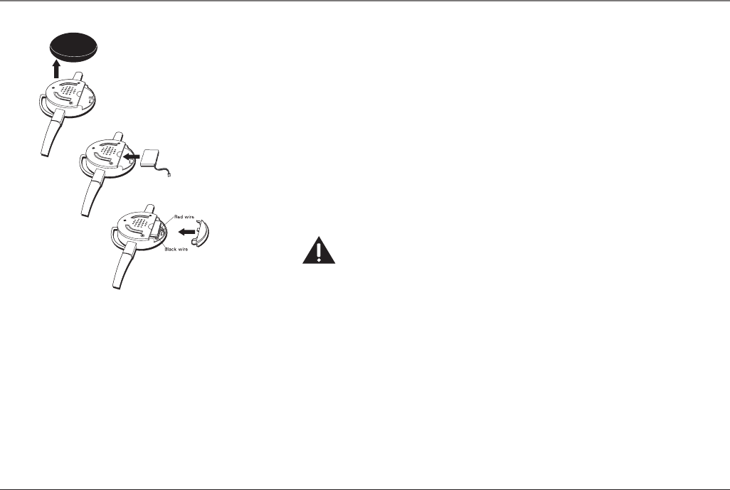
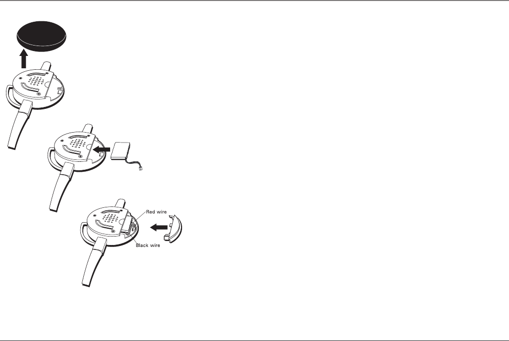
Headset Battery
1. Make sure the telephone is OFF (not in TALK mode) before you replace battery.
2. Remove the foam cover and open the battery compartment door on the head-
set.
3. Disconnect the cord attached to the battery pack from the jack inside the bat-
tery compartment and remove the battery pack.
4. Insert the new battery pack and connect the plug on the battery pack to the
jack inside the compartment.
NOTE: It is important to maintain the polarity (black and red wires) to the jack inside the
compartment. To ensure proper battery installation, the connector is keyed and can be
inserted only one way.
5. Close the battery compartment by snaping the cover into place.
6. Place the headset in the charging cradle.
Allow the headset battery to properly charge (for 16 hours) prior to first use or when you
install a new battery pack. If you do not properly charge the phone, battery performance
will be compromised.
CAUTION: To reduce the risk of fire or personal injury, only use ATLINKS Li-polymer battery
model 5-2682.
Battery Safety Precautions
• Do not burn, disassemble, mutilate, or puncture. Like other batteries of this type,
toxic materials could be released which can cause injury.
• To reduce the risk of fire or personal injury, use only the battery listed in the
User’s Guide.
• Keep batteries out of the reach of children.
Other Information

34
• Remove batteries if storing over 30 days.
Display Messages
The following indicators show the status of a message or of the unit.
BLOCKED CALL The person is calling from a number that has been blocked
from transmission.
BLOCKED NAME The person’s name is blocked from transmission.
DELETE? Prompt asking if you want to erase Caller ID records or one
of the 50 numbers stored in the phone’s outgoing memory.
DELETE ALL? Prompt asking if you want to erase all Caller ID records.
DELETED Prompt confirming the Caller ID /Memory record is erased.
EMPTY Indicates a memory location
is vacant.
END OF LIST Indicates there is no additional information in Caller ID
memory.
ENTER NAME Prompt telling you to enter the name for one of the 10
memory locations.
ENTER TEL NUMBR Prompt telling you to enter the telephone number for one
of the 50 memory locations.
HDST Headset unit.
HDST 00:00 VOL1 Indicates the headset speakerphone is turned on.
INCOMPLETE DATA Caller information has been interrupted during transmission
or the phone line is excessively noisy.
MESSAGE WAITING Indicates a message is available.
MUTE ON Indicates you are muting a telephone conversation to speak
Other Information

35
to a third party .
NEW Indicates call or calls have not been reviewed.
NO CALLS Indicates no CID records have been stored.
NO DATA No Caller ID information was received.
PAGING Someone has pressed the page button on the base.
TALK 00:00 VOL1 Indicates the handset earpiece is active.
UNKNOWN NAME/ The incoming call is from an area not serviced by Caller ID or
CALLER/NUMBER the information was not sent.
Handset Sound Signals
Signal Meaning
A long warbling tone (with ringer on) Signals an incoming call
Two long beeps Confirmation Tone
One short and one long beep Page signal
One short beep every seven seconds Low battery warning
Caller ID
No display
• Make sure the battery is properly charged for 16 hours.
• Make sure the battery is properly installed and connected.
• Replace the battery. Make sure the unit is connected to a non-switched
electrical outlet.
• Disconnect the unit from the electrical outlet and plug it back in.
• Make sure you are subscribed to Caller ID service from your local telephone
Other Information

36
company.
Caller ID error message
• The unit displays this message if it detects anything other than valid Caller ID
information during the silent period after the first ring. This message indicates
the presence of noise on the line.
Telephone
No dial tone
• Check or repeat installation steps.
• Make sure the base power converter is connected to a working electrical outlet.
• Make sure the telephone line cord is connected to the base and the wall jack.
• Disconnect the base from the wall jack and connect another phone to the same
jack. If there is no dial tone in the second phone, the problem might be your
wiring or local service.
• The handset or headset may be out of range. Move closer to the base.
• Make sure the battery is properly charged (for 16 hours).
• Make sure the battery pack is installed correctly.
• Did the handset beep when you pressed the Talk button? Did the display indica-
tor turn on? The battery may need to be charged.
Dial tone is OK, but can’t dial out
• Make sure the tone/pulse setting is programmed correctly.
Handset does not ring
• Make sure the ringer switch on the handset is turned ON.
• You may have too many extension phones on your line. Try unplugging some
phones.
Troubleshooting Tips

37
• See solutions for “No dial tone.”
In use/charge indicator on the base flashes
• Provided your phone company offers voice messaging service and you subscribe
to it, the in use/charge indicator on the base flashes when the phone is not in
use to indicate there is a message waiting. It stops flashing after the message
has been reviewed.
You experience static, noise, or fading in and out
• Handset or headset may be out of range. Move closer to the base.
• Relocate the base
• Charge the battery.
• Make sure the base is not plugged into an outlet with another household appli-
ance.
Unit beeps
• See solutions for “No dial tone.”
• Replace the battery.
Memory dialing
• Make sure you have correctly programmed the memory keys.
• Make sure to follow proper dialing sequence.
• Make sure the tone/pulse setting is programmed correctly.
• If you had a power outage or replaced the battery, reprogram the numbers into
Troubleshooting Tips

38
Troubleshooting Tips
memory.
General Product Care
To keep your telephone working and looking good, follow these guidelines:
• Avoid putting the phone near heating appliances and devices that generate
electrical noise (for example, motors or fluorescent lamps).
• DO NOT expose to direct sunlight or moisture.
• Avoid dropping and other rough treatment to the phone.
• Clean with a soft cloth.
• Never use a strong cleaning agent or abrasive powder because this will damage
the finish.
• Retain the original packaging in case you need to ship the phone at a later date.
Causes of Poor Reception
• Aluminum siding.
• Foil backing on insulation.
• Heating ducts and other metal construction can shield radio signals.
• You’re too close to appliances such as microwaves, stoves, computers, etc.
• Atmospheric conditions, such as strong storms.
• Base is installed in the basement or lower floor of the house.
• Base is plugged into an AC outlet with other electronic devices.
• Baby monitor is using the same frequency.
• Handset or headset battery is low.

39
Troubleshooting Tips
• You’re out of range of the base.
Interference Information
This device complies with Part 15 of the FCC Rules. Operation is subject to the fol-
lowing two conditions: (1) This device may not cause harmful interference; and (2)
This device must accept any interference received, including interference that may
cause undesired operation.
This equipment has been tested and found to comply with the limits for a Class B
digital device, pursuant to Part 15 of the FCC Rules. These limits are designed to pro-
vide reasonable protection against harmful interference in a residential installation.
This equipment generates, uses, and can radiate radio frequency energy and, if not
installed and used in accordance with the instructions, may cause harmful interfer-
ence to radio communications. However, there is no guarantee that interference will
not occur in a particular installation.
If this equipment does cause harmful interference to radio or television reception,
which can be determined by turning the equipment off and on, the user is encour-
aged to try to correct the interference by one or more of the following measures:
• Reorient or relocate the receiving antenna (that is, the antenna for radio or
television that is “receiving” the interference).
• Reorient or relocate and increase the separation between the telecommunica-
tions equipment and receiving antenna.
• Connect the telecommunications equipment into an outlet on a circuit different
from that to which the receiving antenna is connected.
• Consult the dealer or an experienced radio/TV technician for help.
If these measures do not eliminate the interference, please consult your dealer or an
experienced radio/television technician for additional suggestions. Also, the Federal
Communications Commission has prepared a helpful booklet, “How To Identify and
Resolve Radio/TV Interference Problems.” This booklet is available from the U.S.

40
Service Information
Government Printing Office, Washington, D.C. 20402. Please specify stock number
004-000-00345-4 when ordering copies.
Service
If trouble is experienced with this equipment, for repair or warranty information,
please contact customer service at 1-800-511-3180. If the equipment is caus-
ing harm to the telephone network, the telephone company may request that you
disconnect the equipment until the problem is resolved.
This product may be serviced only by the manufacturer or its authorized service
agents. Changes or modifications not expressly approved by ATLINKS USA, Inc. could
void the user’s authority to operate this product. For instructions on how to obtain
service, refer to the warranty included in this guide or call customer service at 1-
800-511-3180.
Or refer inquiries to:
ATLINKS USA, Inc.
Manager, Consumer Relations
P O Box 1976
Indianapolis, IN 46206
Attach your sales receipt to the booklet for future reference or jot down the date
this product was purchased or received as a gift. This information will be valuable if
service should be required during the warranty period.
Purchase date _________________________________________

41
Warranty Information
Name of store _________________________________________
Limited Warranty
What your warranty covers:
• Defects in materials or workmanship.
For how long after your purchase:
• One year, from date of purchase. (The warranty period for rental units begins with the first rental or 45
days from date of shipment to the rental firm, whichever comes first.)
What we will do:
• Provide you with a new or, at our option, a refurbished unit. The exchange unit is under warranty for
the remainder of the original product’s warranty period.
How you get service:
• Properly pack your unit. Include any cables, etc., which were originally provided with the product. We
recommend using the original carton and packing materials.
• ”Proof of purchase in the form of a bill of sale or receipted invoice which is evidence that the product
is within the warranty period, must be presented to obtain warranty service.” For rental firms, proof of
first rental is also required. Also print your name and address and a description of the defect. Send
via standard UPS or its equivalent to:
ATLINKS USA, Inc.
c/o Thomson
11721 B Alameda Ave.
Socorro, Texas 79927
• Pay any charges billed to you by the Exchange Center for service not covered by the warranty.
• Insure your shipment for loss or damage. ATLINKS accepts no liability in case of damage or loss.
• A new or refurbished unit will be shipped to you freight prepaid.
What your warranty does not cover:
• Customer instruction. (Your Owner’s Manual provides information regarding operating instructions
and user controls. Any additional information, should be obtained from your dealer.)
• Installation and setup service adjustments.

42
• Batteries.
• Damage from misuse or neglect.
• Products which have been modified or incorporated into other products.
• Products purchased or serviced outside the USA.
• Acts of nature, such as but not limited to lightning damage.
Product Registration:
• Please complete and mail the Product Registration Card packed with your unit. It will make it easier to
contact you should it ever be necessary. The return of the card is not required for warranty coverage.
Limitation of Warranty:
• THE WARRANTY STATED ABOVE IS THE ONLY WARRANTY APPLICABLE TO THIS PRODUCT.
ALL OTHER WARRANTIES, EXPRESS OR IMPLIED (INCLUDING ALL IMPLIED WARRANTIES OF
MERCHANTABILITY OR FITNESS FOR A PARTICULAR PURPOSE) ARE HEREBY DISCLAIMED. NO
VERBAL OR WRITTEN INFORMATION GIVEN BY ATLINKS USA, INC., ITS AGENTS, OR EMPLOYEES
SHALL CREATE A GUARANTY OR IN ANY WAY INCREASE THE SCOPE OF THIS WARRANTY.
• REPAIR OR REPLACEMENT AS PROVIDED UNDER THIS WARRANTY IS THE EXCLUSIVE REMEDY OF
THE CONSUMER. ATLINKS USA, INC. SHALL NOT BE LIABLE FOR INCIDENTAL OR CONSEQUENTIAL
DAMAGES RESULTING FROM THE USE OF THIS PRODUCT OR ARISING OUT OF ANY BREACH OF
ANY EXPRESS OR IMPLIED WARRANTY ON THIS PRODUCT. THIS DISCLAIMER OF WARRANTIES
AND LIMITED WARRANTY ARE GOVERNED BY THE LAWS OF THE STATE OF INDIANA. EXCEPT TO
THE EXTENT PROHIBITED BY APPLICABLE LAW, ANY IMPLIED WARRANTY OF MERCHANTABILITY
OR FITNESS FOR A PARTICULAR PURPOSE ON THIS PRODUCT IS LIMITED TO THE APPLICABLE
WARRANTY PERIOD SET FORTH ABOVE.
How state law relates to this warranty:
• Some states do not allow the exclusion nor limitation of incidental or consequential damages, or
limitations on how long an implied warranty lasts so the above limitations or exclusions may not apply
to you.
• This warranty gives you specific legal rights, and you also may have other rights that vary from state
to state.
If you purchased your product outside the USA:
• This warranty does not apply. Contact your dealer for warranty information.
Warranty Information
43
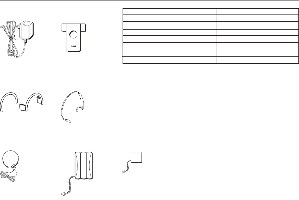
DESCRIPTION MODEL NO.
AC power adaptor (for charger) 5-2678
Belt clip 5-2679
Ear clip pack 5-2680
Headband pack 5-2681
Optional headset (wired) 5-2588
Replacement battery (NiMH for handset) 5-2683
Replacement battery (Li-polymer for headset) 5-2682
AC power adaptor
5-2678
Accessory Information
To place order, have your Visa, MasterCard, or Discover Card ready
and call toll-free 1-800-338-0376.
A shipping and handling fee will be charged upon ordering.
It is required by law to collect appropriate sales tax for each individual state, country,
and locality to which the merchandise is being sent.Items are subject to availability.
Belt clip
5-2679
Ear clip pack
5-2680
Headband pack
5-2681
Optional wired
headset
5-2588
Replacement battery
(NiMH for handset)
5-2683
Replacement battery
(Li-polymar for headset)
5-2682

44
Dialing a Stored Number 30
Display Language 18
Display Messages 34
E
Ear Clip Attachment 12
Equipment Approval Information 2
Exit 22
F
FCC RF Radiation Exposure Statement 3
Flash 22
G
General Product Care 38
H
Handset Battery 32
Handset Layout 16
Handset Memory Retention 32
Handset Set Up 18
Handset Sound Signals 35
Handset Volume 22
Headband Attachment 10
Headset and Belt Clip Operation 31
Headset Battery 33
Headset Layout 17
Headset Set Up 10
Headset Volume 22
Hearing Aid Compatibility 3
A
Adjust Volume from Handset: 22
Adjust Volume from Headset: 22
Answering A Call 20
Area Code 18
Attaching the Belt Clip 31
B
Battery Safety Precautions 33
C
Call Timer 24
Call Transfer 21
Caller ID 25
Caller ID 35
Caller ID error message 36
Caller ID with Call Waiting 25
Causes of Poor Reception 38
Changing a Stored Number 29
Changing the CID Number Format 27
Charger Indicator Light 23
Charger unit 13
Connecting an Optional Headset to the Handset 31
Connecting the AC (Electrical) Power 13
Connecting the Telephone Line 13
D
Default Setting Selection 19
Deleting All Records 27
Deleting Records 26
Deleting the Current Record 26
Dialing a Caller ID Number 27
Index

45
R
Receiving and Storing Calls 25
Redial 21
Replacing the Batteries 32
Reviewing and Deleting Stored Numbers 30
Reviewing Records 25
Ringer Tone 19
Ringer Volume 19
S
Safety Precautions 8
Service 40
Storing a Name and Number in Memory 28
Storing a Redial Number 29
Switch from ear to ear 11, 12
T
Telephone 36
Telephone Jack Requirements 9
Telephone Operation 20
Temporary Tone Dialing 24
Tone/Pulse Dialing 18
Transferring CID Records to Memory 26
Troubleshooting Tips 37
V
Viewing a Stored Number 29
W
Wall base unit 13
Warranty 41
Index
I
Important Installation Information 8
In Use Indicator Light 23
Inserting a Pause in the Dialing Sequence
of a Stored Number 30
Installation Guidelines 8
Installing the Batteries 14
Installing the Earpiece Battery 15
Installing the Handset Battery 14
Interference Information 3
Interference Information 39
Introduction 6
L
Licensing 3
M
Making a Call 20
Memory 28
Mute 21
N
No dial tone 36
No display 35
P
Paging the Handset and Headset 23
Parts Checklist 7
Phone Installation 13

Visit the RCA web site at www.rca.com
Please do not send any products to the Indianapolis address listed in this manual or on the carton.
This will only add delays in service for your product.
ATLINKS USA, Inc.
101 West 103rd Street
Indianapolis, IN 46290
©2005 ATLINKS USA, Inc.
Trademark(s)® Registered
Marca(s) Registrada(s)
Model 25110
00005708 (Rev. 0 DOM E)
05-33
Printed in China