Thomson 2-6976A 900MHz SINGLE-LINE CORDLESS PHONE User Manual 25893 DOM IB E 0
Thomson Inc. 900MHz SINGLE-LINE CORDLESS PHONE 25893 DOM IB E 0
Thomson >
Contents
- 1. users manual 1
- 2. users manual 2
users manual 2

We bring good things to life.
900 MHz Under the Counter Call
Waiting Caller ID Speakerphone/
Answering System
User’s Guide
26976

2
EQUIPMENT APPROVAL INFORMATION
Your telephone equipment is approved for connection to the Public Switched Telephone
Network and is in compliance with parts 15 and 68, FCC Rules and Regulations and the
Technical Requirements for Telephone Terminal Equipment published by ACTA.
1Notification to the Local Telephone Company
On the bottom of this equipment is a label indicating, among other information, the US
number and Ringer Equivalence Number (REN) for the equipment. You must, upon request,
provide this information to your telephone company.
The REN is useful in determining the number of devices you may connect to your
telephone line and still have all of these devices ring when your telephone number is
called. In most (but not all) areas, the sum of the RENs of all devices connected to one line
should not exceed 5. To be certain of the number of devices you may connect to your line
as determined by the REN, you should contact your local telephone company.
A plug and jack used to connect this equipment to the premises wiring and telephone
network must comply with the applicable FCC Part 68 rules and requirements adopted by
the ACTA. A compliant telephone cord and modular plug is provided with this product. It
is designed to be connected to a compatible modular jack that is also compliant. See
installation instructions for details.
Notes
•This equipment may not be used on coin service provided by the telephone company.
•Party lines are subject to state tariffs, and therefore, you may not be able to use your
own telephone equipment if you are on a party line. Check with your local telephone
company.
•Notice must be given to the telephone company upon permanent disconnection of your
telephone from your line.
•If your home has specially wired alarm equipment connected to the telephone line,
ensure the installation of this product does not disable your alarm equipment. If you
have questions about what will disable alarm equipment, consult your telephone
company or a qualified installer.
2Rights of the Telephone Company
Should your equipment cause trouble on your line which may harm the telephone network,
the telephone company shall, where practicable, notify you that temporary discontinuance of
service may be required. Where prior notice is not practicable and the circumstances warrant
such action, the telephone company may temporarily discontinue service immediately. In case
of such temporary discontinuance, the telephone company must: (1) promptly notify you of
such temporary discontinuance; (2) afford you the opportunity to correct the situation; and (3)
inform you of your right to bring a complaint to the Commission pursuant to procedures set
forth in Subpart E of Part 68, FCC Rules and Regulations.
The telephone company may make changes in its communications facilities, equipment,
operations or procedures where such action is required in the operation of its business and not
inconsistent with FCC Rules and Regulations. If these changes are expected to affect the use or
performance of your telephone equipment, the telephone company must give you adequate
notice, in writing, to allow you to maintain uninterrupted service.

3
FCC NUMBER IS LOCATED ON THE CABINET BOTTOM
REN NUMBER IS LOCATED ON THE CABINET BOTTOM
INTERFERENCE INFORMATION
This device complies with Part 15 of the FCC Rules. Operation is subject to the following two
conditions: (1) This device may not cause harmful interference; and (2) This device must
accept any interference received, including interference that may cause undesired operation.
This equipment has been tested and found to comply with the limits for a Class B digital
device, pursuant to Part 15 of the FCC Rules. These limits are designed to provide reasonable
protection against harmful interference in a residential installation.
This equipment generates, uses, and can radiate radio frequency energy and, if not installed
and used in accordance with the instructions, may cause harmful interference to radio
communications. However, there is no guarantee that interference will not occur in a
particular installation.
If this equipment does cause harmful interference to radio or television reception, which can
be determined by turning the equipment off and on, the user is encouraged to try to correct
the interference by one or more of the following measures:
•Reorient or relocate the receiving antenna (that is, the antenna for radio or television that
is “receiving” the interference).
•Reorient or relocate and increase the separation between the telecommunications
equipment and receiving antenna.
•Connect the telecommunications equipment into an outlet on a circuit different from that
to which the receiving antenna is connected.
If these measures do not eliminate the interference, please consult your dealer or an experienced
radio/television technician for additional suggestions. Also, the Federal Communications
Commission has prepared a helpful booklet, “How To Identify and Resolve Radio/TV Interference
Problems.” This booklet is available from the U.S. Government Printing Office, Washington, D.C.
20402. Please specify stock number 004-000-00345-4 when ordering copies.
FCC RF EXPOSURE REQUIREMENTS
For body worn operation, this phone has been tested and meets the FCC RF exposure
guidelines when used with the belt clip supplied with this product. Use of other accessories
may not ensure compliance with FCC RF exposure guidelines.
Specific Absorption Ratio compliance for body-worn operations is restricted to belt-clips,
holsters or similar accessories that have no metallic component in the assembly and must
provide at least 0.7cm separation between the device, including its antenna and the user's body.
HEARING AID COMPATIBILITY
This telephone system meets FCC standards for Hearing Aid Compatibility.

4
(Table of Contents continued on
the following page.)
SEE MARKING ON BOTTOM / BACK OF PRODUCT
RISK OF ELECTRIC SHOCK
DO NOT OPEN
WARNING: TO
PREVENT FIRE OR
ELECTRICAL SHOCK
HAZARD, DO NOT
EXPOSE THIS
PRODUCT TO RAIN
OR MOISTURE.
THE LIGHTNING
FLASH AND ARROW
HEAD WITHIN THE
TRIANGLE IS A
WARNING SIGN
ALERTING YOU OF
“DANGEROUS
VOLTAGE” INSIDE
THE PRODUCT.
CAUTION: TO REDUCE THE
RISK OF ELECTRIC SHOCK, DO
NOT REMOVE COVER (OR
BACK). NO USER
SERVICEABLE PARTS INSIDE.
REFER SERVICING TO
QUALIFIED SERVICE
PERSONNEL.
THE EXCLAMATION
POINT WITHIN THE
TRIANGLE IS A
WARNING SIGN
ALERTING YOU OF
IMPORTANT
INSTRUCTIONS
ACCOMPANYING
THE PRODUCT.
CAUTION:
TABLE OF CONTENTS
EQUIPMENT APPROVAL INFORMATION ......... 2
INTERFERENCE INFORMATION .................... 3
FCC RF EXPOSURE REQUIREMENTS ......... 3
HEARING AID COMPATIBILITY .................... 3
TABLE OF CONTENTS ............................. 4
INTRODUCTION ...................................... 6
HANDSET AND BASE LAYOUT ................... 7
BEFORE Y OU BEGIN ............................... 8
PARTS CHECKLIST .............................. 8
TELEPHONE JACK REQUIREMENTS ......... 8
DIGITAL SECURITY SYSTEM ............ 8
INSTALLATION ........................................ 8
IMPORTANT INSTALLATION GUIDELINES .. 9
INSTALLING THE PHONE ........................... 9
UNDER CABINET MOUNTING ................. 10
PARTS PACKED WITH YOUR UNIT ........ 11
BEFORE MOUNTING ............................. 11
MOUNTING PROCEDURE .................... 12
PROGRAMMING THE PHONE ................... 13
LANGUAGE ..................................... 14
AREA CODE .................................... 14
TONE PULSE ................................... 14
SET CONTRAST ............................... 14
ANSWERING SYSTEM ON/OFF ......... 15
NUMBER OF RINGS .......................... 15
ANSWERING SYSTEM REMOTE
ACCESS SECURITY CODE ...... 15
DEFAULT SETTING ........................... 16
SETTING THE T IME ............................ 16
TELEPHONE OPERATION ........................ 17
RECEIVING A CALL ........................... 17
MAKING A CALL .............................. 17
REDIAL .......................................... 17
FLASH ........................................... 17
IN USE INDICATOR LIGHT .................. 17
CHANNEL BUTTON ........................... 17
TEMPORARY T ONE ............................ 18
EXIT .............................................. 18
FINDING THE HANDSET ..................... 18
RINGER SWITCH .............................. 18
VOLUME ........................................ 18
CALL T IMER .................................... 18
SPEAKERPHONE OPERATION ................... 19
SPEAKERPHONE LOCATION ................. 19
SPEAKERPHONE USE ........................ 19
INDICATOR LIGHT ............................. 19
SPEAKERPHONE VOLUME ................... 19
ANSWERING SYSTEM OPERATION ........... 19
VOICE INSTRUCTIONS ....................... 19
RECORDING THE OUTGOING
ANNOUNCEMENT ................. 20
REVIEWING ANNOUNCEMENT ............. 20
MESSAGES INDICATOR ...................... 20
SCREENING CALLS FROM THE BASE ..... 20
MESSAGE PLAYBACK ........................ 21
ANSWERING SYSTEM MEMORY FULL .. 21
ERASING MESSAGES ........................ 21
LEAVING A MEMO ........................... 21
REMOTE ACCESS ............................. 21
CALLER ID (CID) ................................ 22
CALL WAITING CALLER ID ................ 22
RECEIVING AND STORING CALLS ......... 23
REVIEWING CID RECORDS ................ 23
TRANSFERRING CID RECORDS TO
MEMORY ........................... 23
DELETING THE CID RECORD
SHOWING IN THE DISPLAY ..... 24
DELETING ALL CID RECORDS ............ 24
5
DIALING A CID NUMBER .................. 24
CHANGING THE CID NUMBER
FORMAT ............................. 24
RADIO OPERATION ............................... 25
AM ANTENNA ................................ 25
FM ANTENNA ................................ 25
TURNING ON THE RADIO ................... 25
BAND ............................................ 25
RADIO VOLUME ............................... 25
CHANGING STATIONS ....................... 25
STORING PRESET STATIONS .............. 25
USING PRESET STATIONS ................. 26
MEMORY ............................................ 26
STORING A NAME AND NUMBER IN
MEMORY ........................... 26
CHANGING A STORED NUMBER .......... 27
STORING A REDIAL NUMBER ............. 27
DIALING A STORED NUMBER ............. 27
INSERTING A PAUSE IN THE DIALING
SEQUENCE ......................... 28
REVIEWING AND DELETING STORED
NUMBERS .......................... 28
CHAIN DIALING FROM MEMORY .... 28
PROGRAMMABLE T IMER ......................... 29
SETTING THE T IMER .......................... 29
STARTING THE T IMER ........................ 29
STOPPING THE T IMER ........................ 29
PAUSING THE T IMER ......................... 29
USING THE T IMER WITH
OTHER MODES ................... 30
TALK MODE ................................. 30
CHANGING THE BATTERY ....................... 30
DISPLAY MESSAGES ............................. 31
HANDSET SOUND SIGNALS ................... 32
HEADSET AND BELT CLIP OPERATION ...... 32
CONNECTING AN OPTIONAL
HEADSET TO THE HANDSET ................ 32
CONNECTING THE BELT CLIP .............. 32
TROUBLESHOOTING T IPS ........................ 33
CALLER ID ................................ 33
TELEPHONE ............................... 33
SERVICE ............................................. 35
LIMITED W ARRANTY ............................. 36
INDEX ................................................ 37
ACCESSORY ORDER FORM .................... 39

6
INTRODUCTION
CAUTION: When using telephone equipment, there are basic
safety instructions that should always be followed. Refer to the
IMPORTANT SAFETY INSTRUCTIONS provided with this
product and save them for future reference.
Your Caller ID phone stores and displays specific information, provided
by your local telephone company, to subscribers of Caller ID or similar
caller identification services.
Your Caller ID phone enables you to:
•Identify callers before you answer the phone.
•View the time and date of each incoming call.
•Record up to 40 Caller ID messages sequentially.
•Know who called while you were away or on the phone.
To get the most from your new phone, we suggest that you take a few
minutes right now to read through this user's guide.
IMPORTANT: In order to use all of the Caller ID features of this
phone, you must subscribe to either the standard Name/Number
Caller ID Service or Call Waiting Caller ID Service. To know who is
calling while you are on the phone, you must subscribe to Call
Waiting Caller ID Service.
IMPORTANT: Because cordless phones operate on electricity, you
should have at least one phone in your home that isn’t cordless, in
case the power in your home goes out.
INSTALLATION NOTE: Some cordless telephones operate at
frequencies that may cause interference to nearby TVs, microwave
ovens, and VCRs. To minimize or prevent such interference, the base
of the cordless telephone should not be placed near or on top of a
TV, microwave ovens, or VCR. If such interference continues, move
the cordless telephone farther away from these appliances.

7
HANDSET AND BASE LAYOUT
Fig. 1
Fig. 2
8
BEFORE YOU BEGIN
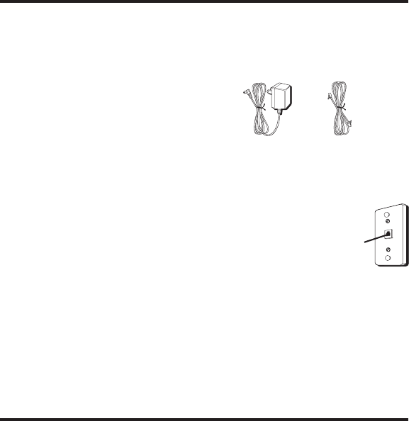
PARTS CHECKLIST
Make sure your package includes the items shown here.
TELEPHONE JACK REQUIREMENTS
To use this phone, you need an RJ11C type modular
telephone jack, which might look like the one
pictured here, installed in your home. If you don’t
have a modular jack, call your local phone company
to find out how to get one installed.
DIGITAL SECURITY SYSTEM
Your cordless phone uses a digital security system to provide protection
against false ringing, unauthorized access, and charges to your phone line.
When you place the handset in the base, the unit verifies its security
code. After a power outage or battery replacement, you should place the
handset in the base for about 20 seconds to reset the code.
INSTALLATION
•Never install telephone wiring during a lightning storm.
•Never install telephone jacks in wet locations unless the jack is
specifically designed for wet locations.
•Never touch non-insulated telephone wires or terminals, unless the
telephone line has been disconnected at the network interface.
•Use caution when installing or modifying telephone lines.
•Temporarily disconnect any equipment connected to the phone such
as faxes, other phones, or modems.
Modular
telephone
line jack
Wall plate
Base Handset Belt clip AC power
supply Telephone
line cord
Fig. 3
Fig. 4
Fig. 5
9
IMPORTANT INSTALLATION GUIDELINES
•Install telephone near both a telephone (modular) jack and an
electrical power outlet.
•Avoid sources of noise, such as a window by a busy street, and electrical
noise, such motors, microwave ovens, and fluorescent lighting.
•Avoid heat sources, such as heating air ducts, heating appliances,
radiators, and direct sunlight.
•Avoid areas of excessive moisture or extremely low temperature.
•Avoid dusty locations.
•Avoid other cordless telephones or personal computers.
INSTALLING THE PHONE
NOTE : The handset can be charged facing up or down.
1. Set the RINGER switch on the handset and Spacemaker
®
base to ON.
2. Place handset in the Spacemaker
®
cradle.
3. The Spacemaker
®
base has a retractable AC plug. Pull down the blades
and plug the base into an electrical outlet.
4. Plug the power supply into an electrical outlet.
CAUTION: Use only the ATLINKS USA, Inc. 5-2541 power
supply that came with this unit. Using other power supplies
may damage the unit.
5. Place the handset in the Spacemaker
®
base.
6. Allow the handset to charge on a flat surface, such as a desk, table or
desktop, for 16 hours prior to first use and wall mounting. If you don't
properly charge the phone, battery performance is compromised.
Fig. 6

10
NOTE: DO NOT connect the telephone line to the modular jack
until the phone has charged for 16 hours.
7. Plug the telephone line cord into the PHONE LINE jack on the bottom
of the base and into a modular jack.
NOTE: The phone automatically defaults to touch-tone dialing.
To change to pulse (rotary) dialing, see "Tone/Pulse" If you
don't know which type of service you have, check with your local
telephone company.
UNDER CABINET MOUNTING
Tools Required:
•Drill and 1/4" Drill Bit • Ruler or Tape Measure
•Nail or Awl • Scissors
•Screwdriver - Phillips • Countersink (optional)
•Masking Tape • Safety Glasses
-----add the line art of the installation here -----
Fig. 7
Fig. 8
11
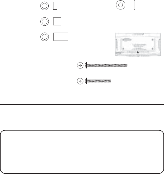
MOUNTING HARDWARE PACKED WITH YOUR UNIT:
3 - 1/4" Spacers 3 - Washers
3 - 1/2" Spacers 2 - Cord hooks
3 - 1" Spacers 1 - Mounting
template
3 - 2 3/4" Phillips head screws
OR
3 - 1 5/8" Phillips head screws
BEFORE MOUNTING
Empty the contents of the cabinet under which the unit is to be mounted
and thoroughly clean the underside to remove any greasy residue. We
recommend the unit be mounted at the front edge of the cabinet.
IMPORTANT: For secure mounting, the screws must go into the unit
to a depth of at least 3/8" If the overall length from the bottom of the
cabinet shelf to the bottom of the overhang is more than 1 3/4", you
will need to use a wood shim. The shim can be located between the
cabinet shelf bottom and the spacers. Make sure the wood is at least
as thick as the excess over 1 3/4". If a shim is necessary, longer screws
(available at most local hardware stores) are required.
Cut out the template on the line indicated. The template size and screw
hole positions are identical to the top of the unit.
Need original art. Has to be exact
size if it is going to be put in book.
Also need exact measurements
(hole spacing)
-----add the line art of cord
hooks here -----
Fig. 9
Fig.10
12
MOUNTING PROCEDURE
1. If your cabinet does not have an overhang:
a) Position the template in the desired location on the underside of
the cabinet, flush with the front edge of the cabinet.
b) Tape the template in place and go to step 2.
If your cabinet has an overhang:
a) Measure the thickness of the overhang.
b) Fold the front of the template downward along the printed
guideline closest to the thickness of your cabinet.
c) Tape folded-down portion to backside of the overhang, and tape
the template to the cabinet underside.
NOTE: If your cabinet has glue blocks or other obstructions, cut out
corresponding areas on the template to clear them. Do not cut out or
cut through the screw holes in the Template.
CAUTION: We recommend safety glasses be worn while
drilling screw holes to prevent the possibility of eye injury.
2. Drill three 1/4" diameter holes through the underside of the cabinet.
TIP: On wooden cabinets you may want to mark and start the drill
holes with a nail or an awl. Be sure to hold the drill very firmly against
the cabinet.
----add drawing showing how the base gets mounted under the cabinet---
---
Fig. 11
Fig. 12
13
Use masking tape above the hole locations on the inside of the cabinet
shelf to reduce splintering.
If installing the unit under a wood cabinet, you may want to
countersink the drilled hole from the INSIDE of the cabinet. This will
eliminate the use of washers and allow the screw head to be flush with
the floor of your cabinet. If you cannot countersink the holes, use the
supplied washers.
3. Remove the template and drill shavings from inside and underneath
the cabinet.
4. If your cabinet doesn't have an overhang, go to step 5.
If your cabinet has an overhang, select the spacer or combination of
spacers equal to or longer than the cabinet overhang.
5. Insert screws from the INSIDE of the cabinet. If you did not
countersink the drilled holes, position the washers, flat side down, and
place the screws in the holes.
If your cabinet does not have an overhang, go to Step 7.
6. Hold the screw heads down while you push the selected spacers onto
the screws under the cabinet. Be sure to push spacers until they are
firmly against the cabinet bottom and/or fully nested (if more than one
is used).
7. Align the unit under the screws. Hold the screw holes on the top of the
unit against the mounting screws and partially tighten the screws.
Do not fully tighten until all 3 screws are installed.
8. Extend the cord towards an electrical outlet and secure by using the
cord hooks to hold the cord out of the way. For a more attractive
appearance, place the cord hooks at the back edge of the cabinet (on
or next to wall) directly over the electrical outlet to be used.
To attach cord hooks peel off the adhesive on the back of the hooks
and attach to a clean, dry surface on the underside of the cabinet or
back wall.

14
PROGRAMMING THE PHONE
There are five programmable menus available:
Language, Area Code,
Tone/Pulse Dialing, Contrast
and
Default.
LANGUAGE
1. Make sure the Spacemaker
®
phone is OFF (in standby mode).
2. Press the program/flash button until
SET LANGUAGE
shows in the
display.
3. Use the CID VOL(+)/CID VOL(-) to select
ENGLISH, FRENCH
or
SPANISH. ENGLISH
is the default.
4. Press the program/flash button to store.
5. Press the *tone/exit button to return to standby mode.
AREA CODE
1. Make sure the Spacemaker
®
phone is OFF (in standby mode).
2. Press the program/flash button until
SET AREA
shows in the display
3. Use the CID VOL(+)/CID VOL(-) to select the three digits of your local
area code.
4. Press the program/flash button to store the selected digit.
5. Repeat Step 3 until all 3 digits are selected.
6. Press the program/flash button to store.
7. P ress the *tone/exit button to return to standby mode.
TONE PULSE
1. Make sure the Spacemaker
®
phone is OFF (in standby mode).
2. Press the program/flash button until
SET TONE/PULSE
shows in the
display
3. Use the CID VOL(+)/CID VOL(-) to select
TONE
or
PULSE
dialing.
TONE
dialing is the default.
4. Press the program/flash button to store.
5. Press the *tone/exit button to return to standby mode.
SET CONTRAST
1. Make sure the Spacemaker
®
phone is OFF (in standby mode).
4.
5.
6.
4.
5.
6.
7.
8.
4.
5.
6.
Spacemaker
eight

15
2. Press the program/flash button until
SET CONTRAST
shows in the
display.
3. Use the CID VOL(+)/CID VOL(-) to select the desired setting.
NOTE: As you scroll through the contrast settings, the display
contrast changes accordingly.
4. Press the program/flash button to store.
5. Press the *tone/exit button to return to standby mode.
ANSWERING SYSTEM ON/OFF
1. Make sure the Spacemaker
®
phone is OFF (in standby mode).
2. Press the program/flash button until
SET ANSWERER
shows in the
display.
3. Use the CID VOL(+)/CID VOL(-) to select
ON
or
OFF
.
4. Press the program/flash button to store.
5Press the *tone/exit button to return to standby mode.
NOTE: The displays shows ANS.ON or ANS.OFF to indicate the status
of the answering system.
NUMBER OF RINGS
1. Make sure the Spacemaker
®
phone is OFF (in standby mode).
2. Press the program/flash button until
RING TO ANSWER
shows in the
display.
3. Use the CID VOL(+)/CID VOL(-) to select
3 , 4, 5
or
6
rings before the
answering system answers the call.
4. Press the program/flash button to store.
5. Press the *tone/exit button to return to standby mode.
ANSWERING SYSTEM REMOTE ACCESS SECURITY CODE
1. Make sure the Spacemaker
®
is OFF (in standby mode).
2. Press the program/flash button until
SECURITY CODE
shows in the
display.
3. Use the CID VOL(+)/CID VOL(-) to select the three digits of your
access code.
4.
5.
6.
4.
5.
6.
4.
5.
6.
4.

16
4. Press the program/flash button to store.
5. Repeat Step 3 until the 3 digit security code is selected.
6. Press the program/flash button to store.
7. P ress the *tone/exit button to return to standby mode.
DEFAULT SETTING
1. Make sure the Spacemaker
®
phone is OFF (in standby mode).
2. Press the program/flash button until
DEFAULT SETTING
shows in the
display.
3. Use the CID VOL(+)/CID VOL(-) to select
NO
or
YES
.
NO
is the default.
4. Press the program/flash button to store.
5. If you select
YES
, the Spacemaker
®
uses the default values as follows:
SET LANGUAGE ENGLISH
SET AREA CODE - - -
SET TONE PULSE TONE
SET CONTRAST 1
ANSWERER ON/ OFF ON
RING TO ANSWER 5
SECURITY CODE 123
6. Press the EXIT button to return to standby mode.
SETTING THE TIME
1. Make sure the Spacemaker
®
phone is OFF (in standby mode).
2. To set the hour press and hold the hour button for one second. The
hour field in the display flashes, and the unit plays back the current
hour.
3. Press the hour button again until the correct hour of the day shows in
the display.
NOTE: If you do not press a button after two seconds the hour
setting is saved and the unit exits the time setting mode.
5.
6.
7.
8.
4.
5.
6.
7.

17
5. Press and hold the hour button again for one second and the unit exits
the hour mode.
6. Repeat this process for setting minutes and day, using the minute and
day buttons instead.
TELEPHONE OPERATION
RECEIVING A CALL
1. Press the TALK/callback button and begin speaking.
2. When finished, press TALK/callback again and hang up the handset.
MAKING A CALL
1. Press the TALK/callback button.
2. Dial a telephone number.
3. When finished, press TALK/callback again and hang up the handset.
REDIAL
While the phone is on, press the redial button to redial the last number
you dialed (up to 32 digits). If you get a busy signal, and want to keep
dialing the number, just press redial again (you don't have to turn the
phone off and back on).
FLASH
Use the flash/program button to activate custom calling services such as
call waiting or call transfer, which are available through your local phone
company.
TIP: Don’t use the TALK/callback button to activate custom calling
services such as call waiting, or you’ll hang up the phone.
IN USE INDICATOR LIGHT
The in use/charge indicator is lit when the handset is charging in the base
or charge cradle, or when the phone is ON. It flashes when you receive a
call or when the page button is pressed.
CHANNEL BUTTON
While talking, you might need to manually change the channel in order to
get rid of static. Press and release the channel/delete button to advance to
the next channel. The current channel number appears on the left side of
the display.
more than two seconds
to
to

18
TEMPORARY TONE
This feature enables pulse (rotary) service phone users to access touch-
tone services offered by banks, credit card companies, etc., by pressing
the *tone/exit button to temporarily make the phone touch-tone
compatible. To get information about your bank account, for example,
you would:
1. Call the bank’s information line.
2. Press the *tone/exit button after your call is answered.
3. Follow the voice instructions to complete your transaction.
4. Hang up when finished. The phone returns to pulse (rotary) service.
EXIT
Press the *tone/exit button to cancel any command you initiated.
FINDING THE HANDSET
This feature helps locate a misplaced handset.
Press the page button on the base. Both handsets beep continuously for
about two minutes or until you press any button on the handset. You may
also press page to cancel.
NOTE: The ringer does not have to be ON for this feature to work.
RINGER SWITCH
The ringer switch must be ON for the handset to ring during incoming calls.
VOLUME
While talking, press the volume buttons (left and right arrows) to adjust
the listening level of the handset's earpiece. There are four volume levels.
Press the right arrow (+) button to increase the volume level, and press
the left arrow (-) button to decrease. VOL 1 is the lowest level and VOL 4 is
the loudest.
CALL TIMER
While you are talking on the phone, the total talk time is displayed on the
bottom line of the display.

19
SPEAKERPHONE OPERATION
SPEAKERPHONE LOCATION
For best speakerphone performance, avoid the following:
•Areas with high background noise. (The microphone might pick up
these sounds and prevent the speakerphone from going into the
receiving mode when you finish talking.)
•Surfaces affected by vibration.
•Recessed areas such as in a corner, under a cupboard, or next to a
cabinet, which can generate an echo effect.
SPEAKERPHONE USE
Note the following guidelines when using the speakerphone:
•The speakerphone works similar to a two-way radio, you can only
listen or talk at one time.
•Stay reasonably close to the phone so that you can be clearly heard by
the person to whom you are talking.
•Press the speaker button to turn on the speakerphone.
•Press the left or right arrow button on the base to adjust the
speakerphone listening level. You will hear a tone when you reach the
minimum or maximum volume level.
INDICATOR LIGHT
The speakerphone is ON when the indicator light is turned on.
SPEAKERPHONE VOLUME
You may choose from eight volume levels.
Use the volume up or down arrow buttons to adjust the speaker volume
to a comfortable level.
ANSWERING SYSTEM OPERATION
This section discusses the buttons and features on the answering machine.
VOICE INSTRUCTIONS
If you need additional assistance, the voice instructions will be
announced after turning on the answering machine function.

20
RECORDING THE OUTGOING ANNOUNCEMENT
For best results when recording, you should be about 9 inches from the
microphone, and eliminate as much background noise as possible.
1. Make sure the Spacemaker
®
unit is ON.
2. Press and hold the announce button. Hold the button down until you
finish the announcement.
3. Begin talking after you hear the beep.
4. Release the button after you finish your announcement.
5. If you choose not to record an outgoing announcement, a default
announcement will play. To return to the default announcement after
you have recorded your own outgoing announcement, press the
announce button and release it when you hear the beep.
Sample Outgoing Announcement
Hi, this is (use your name here), I can’t answer the phone right now, so please leave your
name, number and a brief message after the tone, and I’ll get back to you. Thanks.
REVIEWING ANNOUNCEMENT
•Press and release the announce button to play your outgoing
announcement.
MESSAGES INDICATOR
The base display shows you how many new messages and total
messages you have. The message indicator flashes to indicate you
have new messages.
SCREENING CALLS FROM THE BASE
You can screen incoming calls by waiting for the caller to begin leaving a
message (to hear who it is), then pick up the handset, and press TALK/
callback or the SPEAKER button to talk to the caller. The answering
machine automatically stops recording when you activate the handset or
pick up an extension phone.
TIP: Make sure the volume on the base is set loud enough to hear
your incoming calls.
and release
21
MESSAGE PLAYBACK
The base display lets you know when you have messages. To play
messages, press the play/stop button.
While a message is playing, you can do the following:
•Press the play/stop button to stop the message playback.
•Press and release the rev button to restart the current message;
continue to press and press again the rev button to go to previous
messages.
•Press and release the skip button to go to the next message.
•Press the play/stop button to stop message playback.
ANSWERING SYSTEM MEMORY FULL
When the memory is full, the system answers after 10 rings. You should
erase some of the messages so the answering machine can record new
messages.
ERASING MESSAGES
Erase messages two ways: one message at a time with the erase button
or you may delete all previously played messages with one long press of
the erase button.
•To erase a message while its playing, press and release the erase
button .
•To erase all previously played messages, press and hold the erase
button for 2 seconds until the unit beeps and prompts you that all
messages have been erased.
LEAVING A MEMO
Use the memo feature to leave a message.
1. Press and hold the memo button down until you finish the message.
2. Begin speaking after you hear the beep.
3. Release the memo button after you are finished.
REMOTE ACCESS
This section explains remote access: using any touch-tone phone
1. Dial the phone number for the answering machine.

22
2. After the answering machine answers enter the security code after you
hear the tone.
3. Follow the voice menu to use the answering machine’s remote
functions.
The remote feature enables you to perform the following functions:
PRESS ONE,
TO REVIEW
PRESS ONE,
TO READ THE PREVIOUS MESSAGE
PRESS TWO,
TO PLAY MESSAGES, PRESS TWO AGAIN, TO STOP
PRESS THREE,
TO SKIP
PRESS FOUR,
TO TURN OFF/ON
PRESS SEVEN,
TO REVIEW MENU AGAIN
PRESS ZERO,
WHILE PLAYING A MESSAGE TO ERASE
No valid dialing tones for 30 seconds will hang up the telephone line.
CALLER ID (CID)
This unit receives and displays information transmitted by your local
phone company. This information can include the phone number, date,
and time; or the name, phone number, date, and time. The unit can store
up to 40 calls for later review.
CALL WAITING CALLER ID
Provided you subscribe to Call Waiting Caller ID service from your phone
company, you may see who is calling when you hear the call waiting
beep in the receiver. The caller identification information appears in the
display after you hear the tone.
NEW CALL #
Caller ID nameCaller ID phone number
Time Date New call
7

23
•Press the program/flash button to put the current person on hold so
that you can answer the incoming call.
IMPORTANT: In order to use the Caller ID functions with this unit,
you must subscribe to either the standard Name/Number Caller ID
Service or Call Waiting Caller ID Service. To know who is calling
while you are on the phone, you must subscribe to Call Waiting Caller
ID Service.
RECEIVING AND STORING CALLS
When you receive a call, the information is transmitted by the phone
company to your Caller ID telephone between the first and second ring.
When the memory is full, a new call automatically replaces the oldest call
in memory.
NEW
appears in the display for calls received that have not
been reviewed.
REPT
indicates that a new call from the same number
was received more than once.
NOTE: Check with your local phone company regarding name
service availability.
REVIEWING CID RECORDS
As calls are received and stored, the display is updated to let you know
how many calls have been received.
•Press the CID VOL(+)/CID VOL(-) button to scroll through the call
records from the most recent to the oldest.
•Press the CID VOL(+)/CID VOL(-) button to scroll through the call
records from the oldest to the newest.
TRANSFERRING CID RECORDS TO MEMORY
You may transfer a Caller ID record to your phone’s memory.
NOTE: It is important that you format CID records correctly before
storing in memory. It is not possible to re-format CID records stored
in memory.
1. Use the CID VOL(+)/CID VOL(-) button to scroll to the desired record.
24
2. Press the memory button.
3. Press the desired memory location. Example, press the number 1
button to store the record in memory location 1.
To replace a CID record stored in a memory location with a new
CID record:
1. Repeat steps 1 through 3.
2. Press the MEMORY button and
REPLACE MEMO?
shows in the display.
3. Press * tone/exit to exit, or press memory again and the new CID
record replaces the old CID record in that memory location. You will
hear a confirmation tone.
DELETING THE CID RECORD SHOWING IN THE DISPLAY
1. Make sure the phone is OFF (not in TALK mode).
2. Use the CID VOL(+)/CID VOL(-)) button to display the desired
Caller ID record.
3. Press delete/channel. The display shows
DELETE?
4. Press delete/channel again to erase the record. You will hear a
confirmation tone. The display shows
DELETED
. Then the next Caller ID
record shows in the display.
DELETING ALL CID RECORDS
1. Make sure the phone is OFF (not in TALK mode).
2. Use the CID VOL(+)/CID VOL(-) button to display any Caller ID record.
3. Press and hold delete/channel button until the unit beeps and
DELETE
ALL?
shows in the display.
4. Press delete/channel again to erase all records. You will hear a
confirmation tone, and the display shows
NO CALLS
.
DIALING A CID NUMBER
1. Make sure the phone is OFF (not in TALK mode).
2. Use the CID VOL(+)/CID VOL(-) button to display the desired
Caller ID record.
3. Press TALK/callback button. The number dials automatically.
CHANGING THE CID NUMBER FORMAT
The format button lets you change the format of the displayed CID
number. The available formats are as follows.

25
7-digit 7-digit telephone number.
10-digit 3-digit area code + 7-digit telephone number.
11-digit long distance code “1” + 3-digit area code + 7-digit
telephone number.
1. Use the CID VOL(+)/CID VOL(-) button to scroll to the number you want
to call back.
2. If the number does not dial as shown, press the format button. Repeat
if necessary, until the correct number of digits are shown.
3. Press TALK/callback button. The number dials automatically.
RADIO OPERATION
AM ANTENNA
A built in antenna is used for AM reception .
FM ANTENNA
The power cord acts as the FM antenna. For best reception, be sure the
power cord is stretched to its fullest length. Do not coil or bunch the cord
together. Changing the position of the power cord may improve
reception.
TURNING ON THE RADIO
Use the radio on/off button to turn the radio on or off.
BAND
Use the FM/AM switch to select which broadcast band you want the radio
to receive.
RADIO VOLUME
Use the volume buttons to adjust the radio volume. The display shows
the current volume setting.
CHANGING STATIONS
Use the tune buttons to change the radio station. If you hold down either
button, the radio automatically scans for radio stations.
seek

26
STORING PRESET STATIONS
When a radio station is tuned in, press and hold the preset button for
three seconds, then select the preset number using the skip and rev
buttons. Up to five AM and FM radio stations may be stored.
USING PRESET STATIONS
To listen to a PRESET RADIO STATION on the current band, press the
preset button to enter the selection mode, followed by the skip or rev
button to select a preset station.
MEMORY
Store up to ten 24-digit numbers in memory for quick dialing. This
memory feature is in addition to the 40 Caller ID records that can be
stored in the Caller ID memory log.
STORING A NAME AND NUMBER IN MEMORY
1. Make sure the phone is OFF (not in TALK mode).
2. Press the memory button.
3. Press the desired memory location (0 through 9).
4. Press the memory button again. The display shows
ENTER NAME
.
NOTE: If you don't want to enter the name, skip step 6.
5. Use the handset’s touch-tone pad to enter a name (up to 15
characters). More than one letter is stored in each number key.
For example, to enter the name Bill Smith, press the two key twice for
the letter B, press the four key three times for the letter I, and press the
five key three times for the letter L. After one second, press the five
key three times again for the second letter L and press the one key to
insert a space between the letter L and S. Press the seven key four
times for the letter S, press the six key once for the letter M, press the
four key three times for the letter I, press the eight key once for the
letter T, and press the four key twice for the letter H.
NOTE: If you enter a wrong letter, press channel/delete button to
backspace.
6. Press the memory button to save the name. The display shows
ENTER TEL NUMBR
.
27
7. Use the touch-tone pad to enter the area code followed by the
telephone number you want to store (up to 24 digits).
8. Press memory again to store the number. You will hear a
confirmation tone.
CHANGING A STORED NUMBER
1. Repeat steps 1 through 7 in Storing a Name and Number in Memory.
2. Press the memory button and
REPLACE MEMO?
shows in the display.
3. Press *tone/exit to exit, or press the memory button to store the
number. You will hear a confirmation tone.
STORING A REDIAL NUMBER
1. Repeat steps 1 through 6 in Storing a Name and Number in Memory.
2. Press the redial button.
3. Press the memory button to store the number. You will hear a
confirmation tone.
To r eplace an old redial number stored in a memory locations with a new
redial number:
1. Repeat steps 1 through 6 in Storing a Name and Number in Memory.
2. Press the memory button and
REPLACE MEMO?
shows in the display.
3. Press *tone/exit to exit, or press the memory button again and the
new redial number replaces the old redial number in that memory
location. You will hear a confirmation tone.
DIALING A STORED NUMBER
1. Make sure the phone is ON by pressing the TALK/callback button.
2. Press memory button.
3. Press the number (0-9) for the desired memory location. The number
dials automatically.
- OR -
1. Make sure the phone is OFF (not in TALK mode).
2. Press memory button.
3. Use the CID/VOL (-) arrow or CID/VOL (+) arrow button to scroll through
the numbers stored in memory until the desired number is shown.
4. Press TALK/callback. The numbers dial automatically.

28
IMPORTANT: If you make test calls to emergency numbers stored in
memory, remain on the line and briefly explain the reason for the
call to the dispatcher. Also, it’s a good idea to make these calls in off-
peak hours, such as early morning or late evening.
INSERTING A PAUSE IN THE DIALING SEQUENCE
When storing information in memory, press the # pause button twice
within one second to insert a delay in the dialing sequence of a stored
telephone number when a pause is needed to wait for a dial tone (for
example after you dial 9 for an outside line, or to wait for a computer
access tone). Pause shows on the display as a
“P
.
“
Each pause counts as
1 digit in the dialing sequence.
REVIEWING AND DELETING STORED NUMBERS
1. Press memory, then use the CID/VOL (-) arrow or CID/VOL (+) arrow
button to view the entry.
2. While the entry is displayed, press channel/delete button to delete the
entry. The display shows
DELETE?
3. Press channel/delete again to delete the entry.
DELETED
shows in
the display.
CHAIN DIALING FROM MEMORY
Use this feature to make calls which require a sequence of numbers such
as using a calling card for a frequently called long distance number.
Basically, you dial each part of the sequence from memory. The following
example shows how you can use chain dialing to make a call through a
long distance service:
The Number For Memory Location
Long distance access number 7
Authorization code 8
Frequently called long distance number 9
1. Make sure the phone is ON.
2. Press memory and then press 7.
3. When you hear the access tone, press memory again and then press 8.
4. At the next access tone, press memory and then 9.

29
TIP: Wait for the access tones between pressing the memory button, or
your call might not go through.
PROGRAMMABLE TIMER
Keep track of baking or cooking times with the built-in, easy-to-read
digital display timer. A loud two-minute alarm sounds when countdown
time expires.
SETTING THE TIMER
1. Make sure the phone is OFF (not in TALK mode).
2. Press the timer button.
3. The unit displays
SET TIMER 00 MIN 00 SEC
, and the first digit
(minutes) blinks in the display.
4. Press the desired number 0-9.
5. After the first digit is entered, the second digit blinks.
6. Continue entering digits for the number of seconds you want to set.
NOTE: Maximum timing period is 99 minutes 99 seconds, while one
minute equals 60 seconds.
STARTING THE TIMER
When the countdown time is set,
1. Press the timer button to start counting down. You will hear a
confirmation tone.
2. When the countdown time expires,
TIMER ON 00 MIN 00 SEC
shows in
the display, and an alarm sounds for two minutes.
STOPPING THE TIMER
When the phone is OFF (not in TALK mode), press the *tone/exit or timer
button to stop the countdown and return to standby mode.
NOTE: The timer stops automatically if the battery charge is low
or empty.

30
PAUSING THE TIMER
Press the timer button to pause the countdown. The remaining time is
held. Press timer again to resume the countdown.
USING THE TIMER WITH OTHER MODES
Once the countdown starts, the timer keeps counting down until time
runs out and the alarm sounds even if the phone is in other modes. To
cancel the timer while in other modes, press *tone/exit or timer. The
timer does not show in the display in other modes. To view the remaining
time, press the timer button.
TALK MODE
1. Press the timer button to view the remaining time, and press timer
again to display the channel number, call counter, and volume level.
•When the countdown is complete,
TIMER STOP
shows in the
display, and an alarm sounds for two minutes.
2. Press the timer button to stop the alarm and display the channel
number, call counter, and volume level.
NOTE: To maximize the countdown timer's functionality, ensure the
battery is fully charged.
CHANGING THE BATTERY
Make sure the telephone is OFF before you replace battery.
1. Remove the battery compartment door.
2. Disconnect the battery plug from the jack in the handset battery
compartment and remove the battery pack.
3. Insert the new battery pack and connect the cord into the jack inside the
handset.
4. Put the battery compartment door back on.
5. Place handset in the Spacemaker
®
to charge. Allow the handset battery
to properly charge (for 16 hours) prior to first use or when you install a
new battery pack. If you do not properly charge the phone, battery
performance will be compromised.
CAUTION: To reduce the risk of fire or personal injury, use
only the battery 5-2461.

31
DISPLAY MESSAGES
The following indicators show the status of a message or of the unit.
INCOMPLETE DATA Caller information has been interrupted during
transmission or the phone line is excessively noisy.
ENTER NAME Prompt telling you to enter the name for one of the
10 memory locations.
ENTER TEL NUMBR Prompt telling you to enter the telephone number
for one of the 10 memory locations.
PRESS AND HOLD Prompt telling you to re-register the handset to
FORMAT KEY base set.
DELETE? Prompt asking if you want to erase Caller ID records
or one of the 10 numbers stored in the phone’s
outgoing memory.
DELETE ALL? Prompt asking if you want to erase all Caller ID
records.
DELETED Prompt confirming the Caller ID /Memory record
is erased.
END OF LIST Indicates that there is no additional information in
Caller ID memory.
BLOCKED NUMBER The callers telephone number is blocked from
transmission.
HANDSET IN USE Indicates that another handset is in use.
NEW Indicates call or calls have not been reviewed.
UNKNOWN NAME/ The incoming call is from an area not serviced by
CALLER/NUMBER Caller ID or the information was not sent.
PAGING Someone has pressed the page button on the base.
BLOCKED CALL The call information is blocked from transmission.
BLOCKED NAME The caller’s name is blocked from transmission.
REPT Repeat call message. Indicates that a new call from
the same number was received more than once.
/spacemaker
LINE
the line

32
NO DATA No Caller ID information was received.
EMPTY Indicates a memory location is vacant.
NO CALLS Indicates no CID records have been stored.
MESSAGE WAITING Indicates a message is available.
HANDSET SOUND SIGNALS
Signal Meaning
A long warbling tone Signals an incoming call
(with ringer on)
Two long beeps Confirmation Tone
One short and one long beep Page signal
One short beep Low battery warning
every seven seconds
HEADSET AND BELT CLIP OPERATION
CONNECTING AN OPTIONAL HEADSET TO THE HANDSET
For hands free conversation, connect the headset (optional) to the
HEADSET jack as shown. The handset receiver and microphone are
disabled when the headset is connected.
TIP: To order a headset, please refer to the accessory order form at the
end of this user’s guide.
Adjust the headset to rest comfortably on top of your head and over your
ear. Move the microphone to approximately 2 to 3 inches from your mouth.
•Press the TALK/callback button to answer or place a call before using
the headset.
CONNECTING THE BELT CLIP
There are two slots, one on each side of the handset.
•Attach the belt clip by inserting the sides of the belt clip into the slots.
Snap the ends of the belt clip into place.

33
TROUBLESHOOTING TIPS
CALLER ID
No Display
•Check or replace the handset batteries.
•Make sure the unit is connected to a non-switched electrical outlet.
Disconnect the unit from the plug and plug it in again.
•You must subscribe to Caller ID service from your local telephone
company to receive CID information.
Caller ID Error Message
•The unit displays this message if it detects anything other than valid
Caller ID information during the silent period after the first ring. This
message indicates the presence of noise on the line.
TELEPHONE
No dial tone
•Check or repeat installation steps:
Make sure power cords are connected to working electrical outlets.
Make sure the telephone line cord is connected to the telephone line
jacks (base and wall).
•Disconnect the base from the wall telephone jack and connect another
phone to the same jack. If there is no dial tone in the second phone, the
problem might be your wiring or local service.
•Handset may be out of range of base. Move closer to base.
•Make sure the battery is properly charged (16 hours).
•Make sure the battery pack is correctly installed.
•Did the handset beep when you pressed the TALK/callback button? Did
the display indicator turn on? The battery may need to be charged.
Dial tone is OK, but can't dial out
• Make sure the tone/pulse setting is programmed correctly.

34
Handset does not ring
•Make sure the ringer switch on the handset is turned to ON.
•You may have too many extension phones on your line. Try
unplugging some phones.
•See solutions for “No dial tone.”
In use/charge indicator on the base flashes
•Provided your phone company offers voice messaging service and you
subscribe to it, the in use/charge indicator on the base flashes when
the phone is not in use to indicate there is a message waiting. It stops
flashing after the message is reviewed.
Handset Loses Registration ID
•If the handset becomes unregistered, messages in the handset display
prompt you to re-register the handset to the base to restore the
registration ID.
•If registration is not successful, disconnect the base power supply and
re-connect it after a few seconds to reset the unit.
You experience static, noise, or fading in and out
•Change channels
•Handset may be out of range of base. Move closer to base.
•Relocate the base.
•Charge the battery.
•Make sure base is not plugged into an outlet with another
household appliance.
Unit beeps
•Place handset in base for 20 seconds to reset the security code. If that
doesn’t work, charge battery for 16 hours.
•See solutions for “No dial tone.”
•Replace battery.

35
Memory Dialing
•Did you program the memory location keys correctly?
•Did you follow proper dialing sequence?
•Make sure the tone/pulse setting is programmed correctly.
•Did you reprogram numbers into memory after power outage or
battery replacement?
S
ERVICE
If trouble is experienced with this equipment, for repair or warranty
information, please contact customer service at
1-800-448-0329. If the equipment is causing harm to the telephone network,
the telephone company may request that you disconnect the equipment
until the problem is resolved.
This product may be serviced only by the manufacturer or its authorized
service agents. Changes or modifications not expressly approved by
ATLINKS USA, Inc. could void the user’s authority to operate this product.
For instructions on how to obtain service, refer to the warranty included
in this guide or call customer service at 1-800-448-0329.
Or refer inquiries to:
ATLINKS USA, Inc.
Manager, Consumer Relations
P O Box 1976
Indianapolis, IN 46206
Attach your sales receipt to the booklet for future reference or jot down
the date this product was purchased or received as a gift. This
information will be valuable if service should be required during the
warranty period.
Purchase date _________________________________________________
Name of store _________________________________________________

36
LIMITED WARRANTY
What your warranty covers:
•Defects in materials or workmanship.
For how long after your purchase:
•One year, from date of purchase.
(The warranty period for rental units begins with the first rental or 45 days from date of shipment to the rental firm,
whichever comes first.)
What we will do:
•Provide you with a new or, at our option, a refurbished unit. The exchange unit is under warranty for the remainder of the
original product’s warranty period.
How you get service:
•Properly pack your unit. Include any cables, etc., which were originally provided with the product. We recommend using the
original carton and packing materials.
•”Proof of purchase in the form of a bill of sale or receipted invoice which is evidence that the product is within the
warranty period, must be presented to obtain warranty service.” For rental firms, proof of first rental is also required. Also
print your name and address and a description of the defect. Send via standard UPS or its equivalent to:
ATLINKS USA, Inc.
c/o Thomson
11721 B Alameda Ave.
Socorro, Texas 79927
•Pay any charges billed to you by the Exchange Center for service not covered by the warranty.
•Insure your shipment for loss or damage. ATLINKS accepts no liability in case of damage or loss.
•A new or refurbished unit will be shipped to you freight prepaid.
What your warranty
does not
cover:
•Customer instruction. (Your Owner’s Manual provides information regarding operating instructions and user controls. Any
additional information, should be obtained from your dealer.)
•Installation and setup service adjustments.
•Batteries.
•Damage from misuse or neglect.
•Products which have been modified or incorporated into other products.
•Products purchased or serviced outside the USA.
•Acts of nature, such as but not limited to lightning damage.
Product Registration:
•Please complete and mail the Product Registration Card packed with your unit. It will make it easier to contact you should
it ever be necessary. The return of the card is not required for warranty coverage.
Limitation of Warranty:
•THE WARRANTY STATED ABOVE IS THE ONLY WARRANTY APPLICABLE TO THIS PRODUCT. ALL OTHER WARRANTIES,
EXPRESS OR IMPLIED (INCLUDING ALL IMPLIED WARRANTIES OF MERCHANTABILITY OR FITNESS FOR A PARTICULAR
PURPOSE) ARE HEREBY DISCLAIMED. NO VERBAL OR WRITTEN INFORMATION GIVEN BY ATLINKS USA, INC., ITS
AGENTS, OR EMPLOYEES SHALL CREATE A GUARANTY OR IN ANY WAY INCREASE THE SCOPE OF THIS WARRANTY.
•REPAIR OR REPLACEMENT AS PROVIDED UNDER THIS WARRANTY IS THE EXCLUSIVE REMEDY OF THE CONSUMER. ATLINKS
USA, INC. SHALL NOT BE LIABLE FOR INCIDENTAL OR CONSEQUENTIAL DAMAGES RESULTING FROM THE USE OF THIS
PRODUCT OR ARISING OUT OF ANY BREACH OF ANY EXPRESS OR IMPLIED WARRANTY ON THIS PRODUCT. THIS DISCLAIMER
OF WARRANTIES AND LIMITED WARRANTY ARE GOVERNED BY THE LAWS OF THE STATE OF INDIANA. EXCEPT TO THE EXTENT
PROHIBITED BY APPLICABLE LAW, ANY IMPLIED WARRANTY OF MERCHANTABILITY OR FITNESS FOR A PARTICULAR
PURPOSE ON THIS PRODUCT IS LIMITED TO THE APPLICABLE WARRANTY PERIOD SET FORTH ABOVE.
How state law relates to this warranty:
•Some states do not allow the exclusion nor limitation of incidental or consequential damages, or limitations on how long an
implied warranty lasts so the above limitations or exclusions may not apply to you.
•This warranty gives you specific legal rights, and you also may have other rights that vary from state to state.
If you purchased your product outside the USA:
•This warranty does not apply. Contact your dealer for warranty information.

37
INDEX
A
Accessory Order Form 39
AM Antenna 25
Answering System Memory Full 21
Answering System ON/OFF 15
Answering System Operation 19
Answering System Remote Access
Security Code 15
Area Code 14
B
Band 25
Before Mounting 11
Before You Begin 8
C
Call Timer 18
Call Waiting Caller ID 22
Caller ID 33
Caller ID (CID) 22
Chain Dialing from Memory 28
Changing a Stored Number 27
Changing Stations 25
Changing the Battery 30
Changing the CID
Number Format 24
Channel Button 17
Connecting an Optional Headset to
the Handset 32
Connecting the Belt Clip 32
D
Default Setting 16
Deleting All CID Records 24
Deleting the CID Record Showing in
the Display 24
Dialing a CID Number 24
Dialing a Stored Number 27
Digital Security System 8
Display Messages 31
E
Equipment Approval Information 2
Erasing Messages 21
Exit 18
F
FCC RF Exposure Requirements 3
Finding the Handset 18
Flash 17
FM Antenna 25
H
Handset and Base Layout 7
Handset Sound Signals 32
Headset and Belt Clip Operation 32
Hearing Aid Compatibility 3
I
Important Installation Guidelines 9
In Use Indicator Light 17
Indicator Light 19
Inserting a Pause in the Dialing
Sequence 28
Installation 8
Installing the Phone 9
Interference Information 3
Introduction 6
L
Language 14
Leaving a Memo 21
Limited Warranty 36
M
Making a Call 17
Memory 26
Message Playback 21
Messages Indicator 20
38
Mounting Hardware Packed with
Your Unit: 11
Mounting Procedure 12
N
Number of Rings 15
P
Parts Checklist 8
Pausing the Timer 29
Programmable Timer 29
Programming the Phone 13
R
Radio Operation 25
Radio Volume 25
Receiving a Call 17
Receiving and Storing Calls 23
Recording the Outgoing
Announcement 20
Redial 17
Remote Access 21
Reviewing and Deleting Stored
Numbers 28
Reviewing Announcement 20
Reviewing CID Records 23
Ringer Switch 18
S
Screening Calls from the Base 20
Service 35
Set Contrast 14
Setting the Time 16
Setting the Timer 29
Speakerphone Location 19
Speakerphone Operation 19
Speakerphone Use 19
Speakerphone Volume 19
Starting the Timer 29
Stopping the Timer 29
Storing a Name and Number in
Memory 26
Storing a Redial Number 27
Storing Preset Stations 25
T
TALK Mode 30
Telephone 33
Telephone Jack Requirements 8
Telephone Operation 17
Temporary Tone 18
Tone Pulse 14
Transferring CID Records
to Memory 23
Troubleshooting Tips 33
Turning on the Radio 25
U
Under Cabinet Mounting 10
Using Preset Stations 26
Using the Timer with
Other Modes 30
V
Voice Instructions 19
Volume 18

39
Please make sure that this form has been filled out completely.
*Prices are subject to change without notice.
Total Merchandise.........................................$_______________
Sales Tax........................................................$_______________
We are required by law to collect the appropriate sales tax for each individual
state, county, and locality to which the merchandise is being sent.
Use VISA or Master Card or Discover preferably. Money order or check must
be in U.S. currency only. No COD or Cash. All accessories are subject to
availability. Where applicable, we will ship a superseding model.
Shipping/Handling....................................... $_______________
Total Amount Enclosed.................................$_______________
Mail order form and money order or check (in U.S. currency)
made payable to Thomson to:
Thomson
Mail Order Department
P.O. Box 8419
Ronks, PA 17573-8419
Name_______________________________________________________
Address_____________________________________ Apt.____________
City ________________________State________ ZIP_________________
Daytime Phone Number ( )_______________________________
____________________________________________________________________
Authorized Signature
A
CCESSORY
O
RDER
F
ORM
CUSTOMER: CUT ALONG DOTTED LINE. ✂
$5.00
My card expires:
Copy the number above your name on the Master Card.
For credit card purchases
Your complete charge card number, its expiration date and your
signature are necessary to process all charge card orders.
Copy your complete account number from your VISA card.
My card expires:
Copy your complete account number from your
Master Card or Discover.
To order, call 1-800-338-0376 (for accessories only) or complete this order form.
DESCRIPTION
AC power supply
CATALOG NUMBER TOTAL
QUANTITY
PRICE*
5-2557 $10.85
Belt clip
5-2588 $36.35
Headset
$9.95
5-2541 $24.95
Replacement battery 5-2461
5-2556
5-2587
5-2576
5-2461
BLACK WHITE
Charge cradle 5-2602 $XX.XX
5-2599
Model 26976
16201210 (Rev. 0 E/S)
03-40
Printed in China
ATLINKS USA, Inc.
101 West 103rd Street
Indianapolis, IN 46290
© 2003 ATLINKS USA, Inc.
Trademark(s) ® Registered
Marca(s) Registrada(s)