Thomson GC801701 Wireless HD Antenna bracket User Manual HDwirelessUserGuide
Thomson Inc. Wireless HD Antenna bracket HDwirelessUserGuide
UserManual.wiki
>
Thomson
>
GC801701 User Manual
Users guide
Navigation menu
Upload a User Manual
Namespaces
Wiki Guide
HTML
PDF
Info
Views
User Manual
Discussion / Help
Navigation

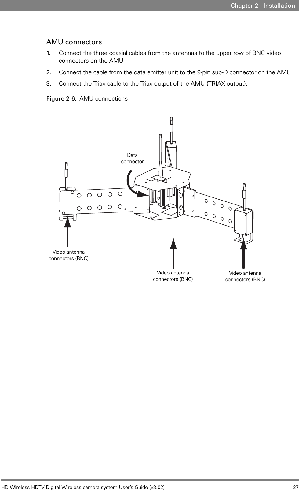
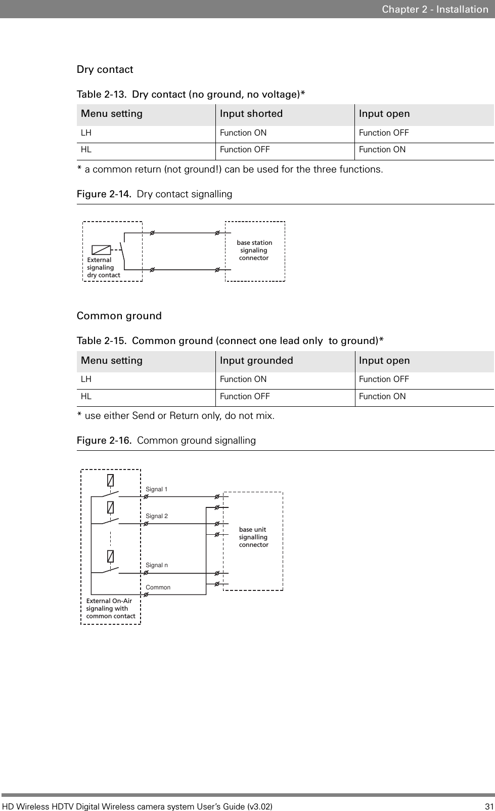

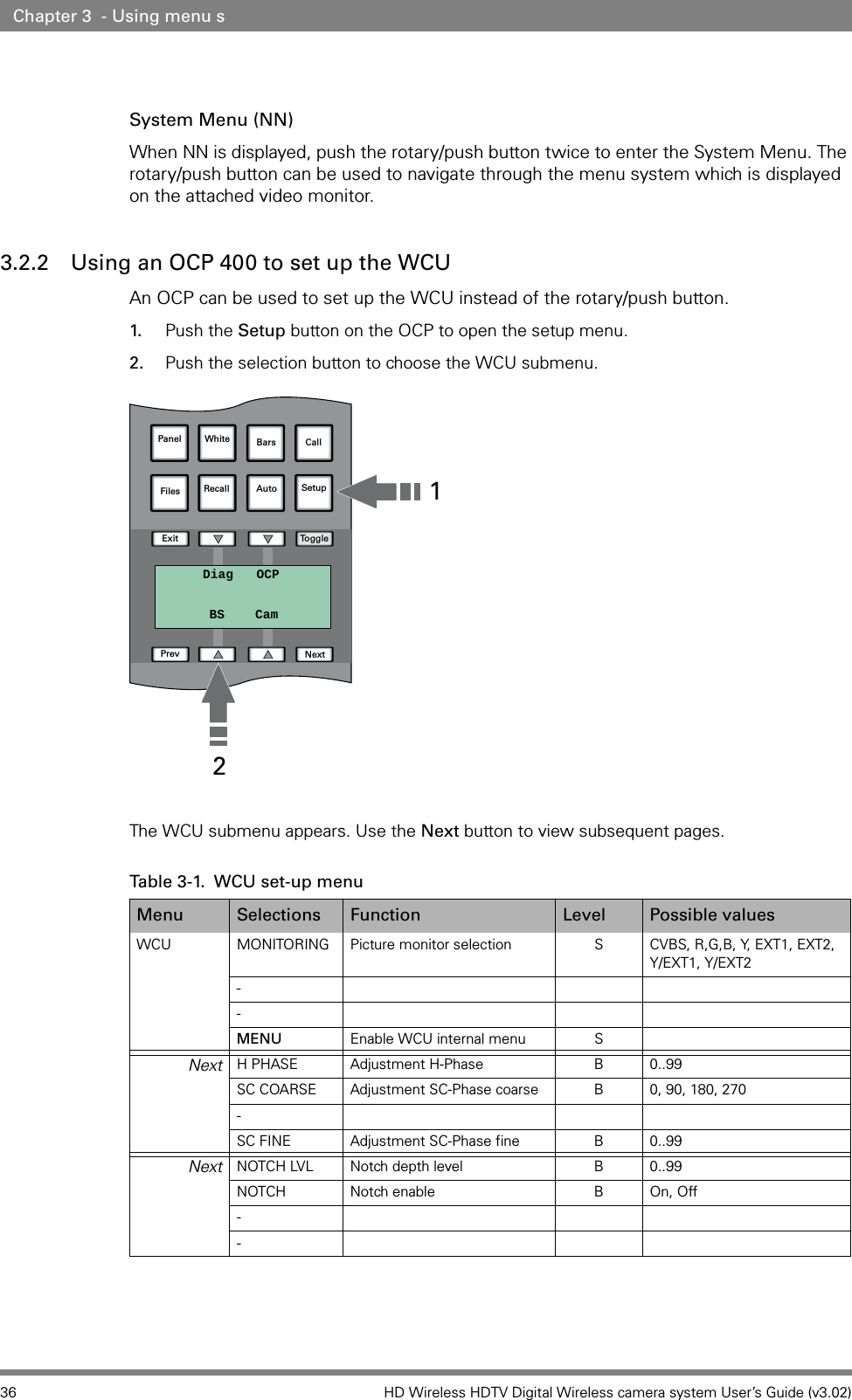

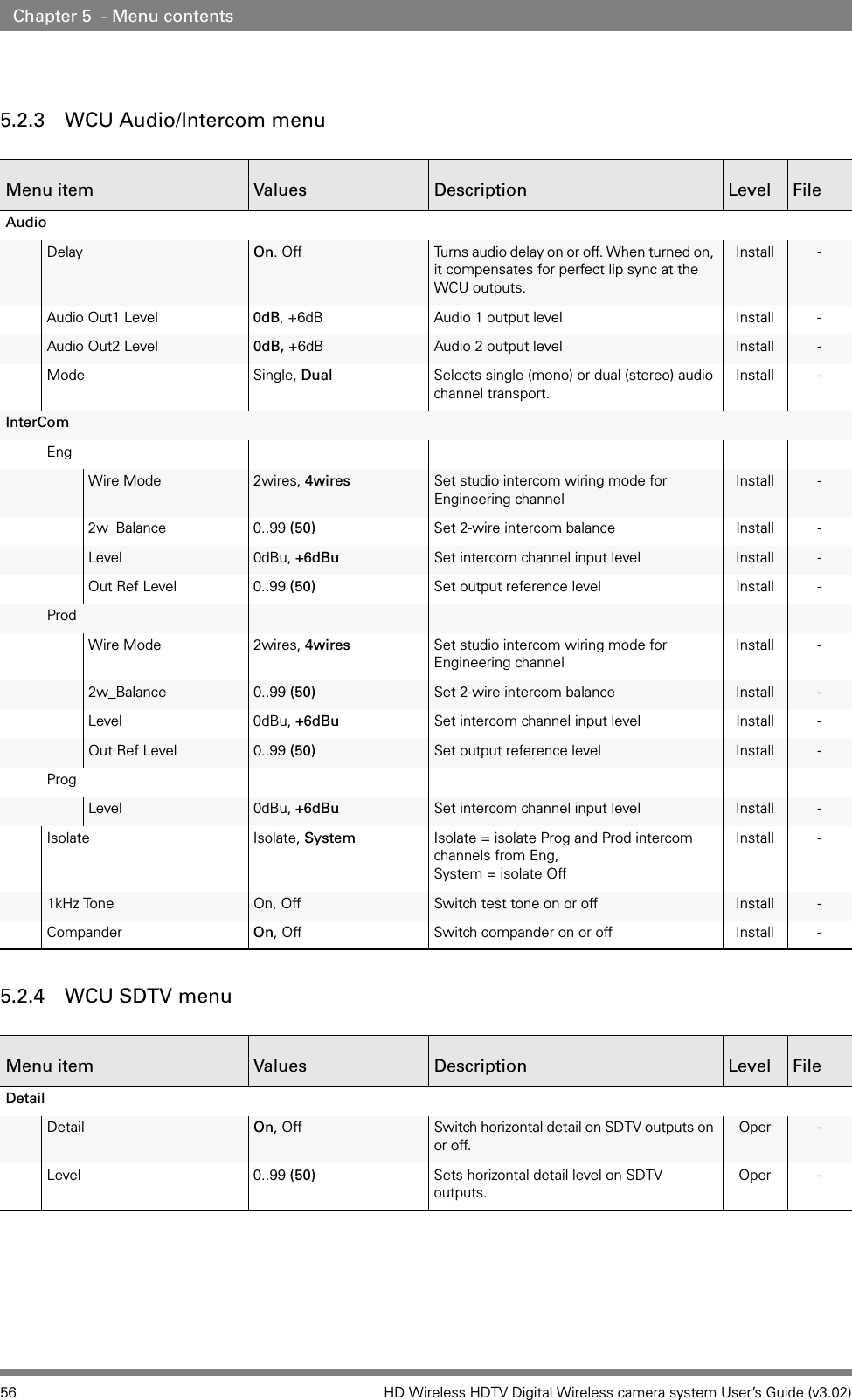
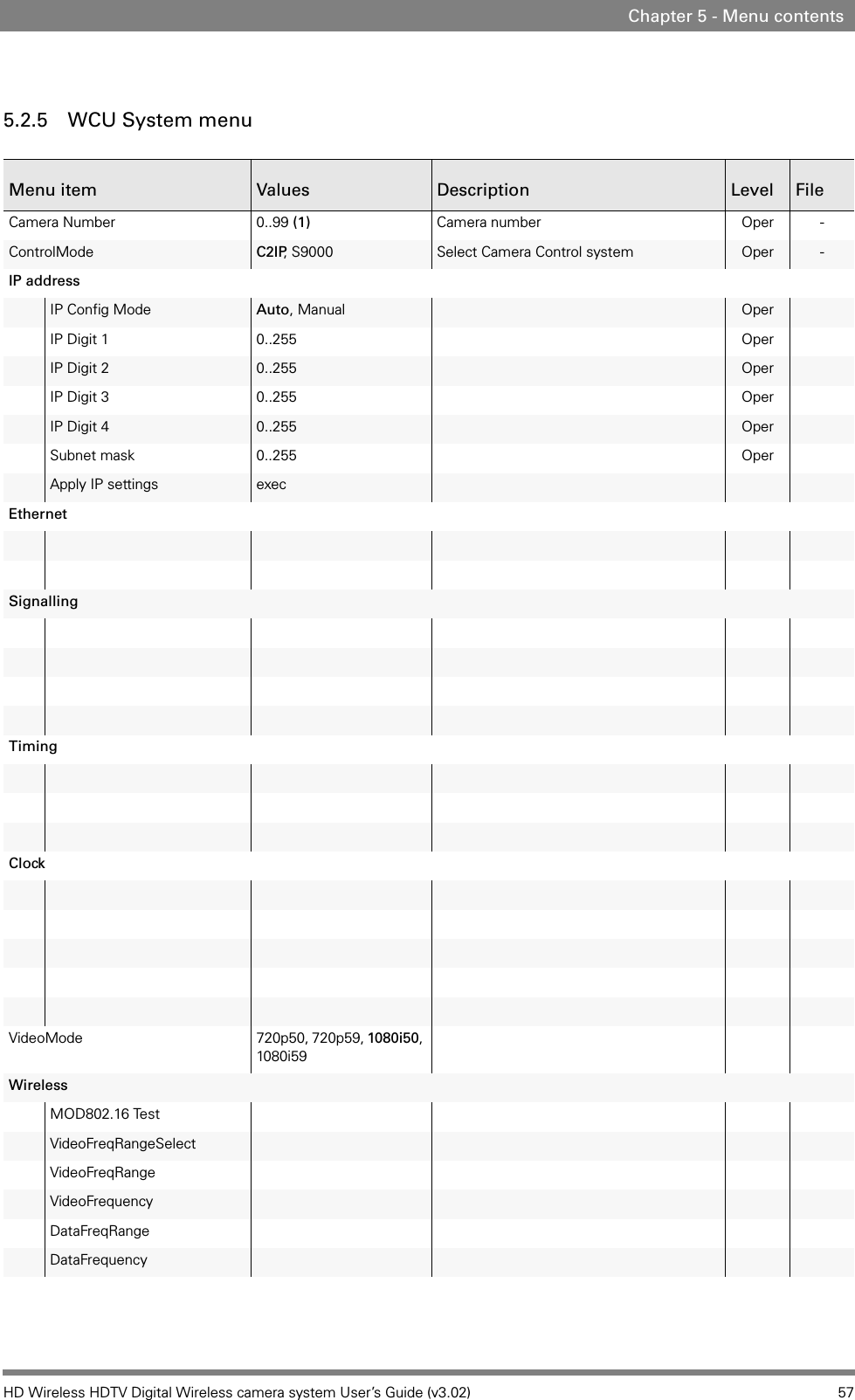
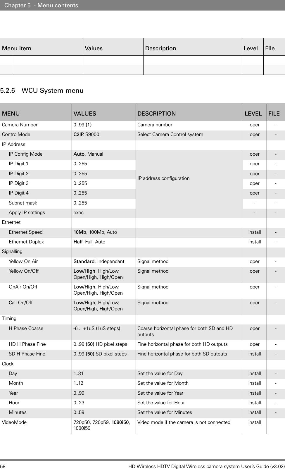
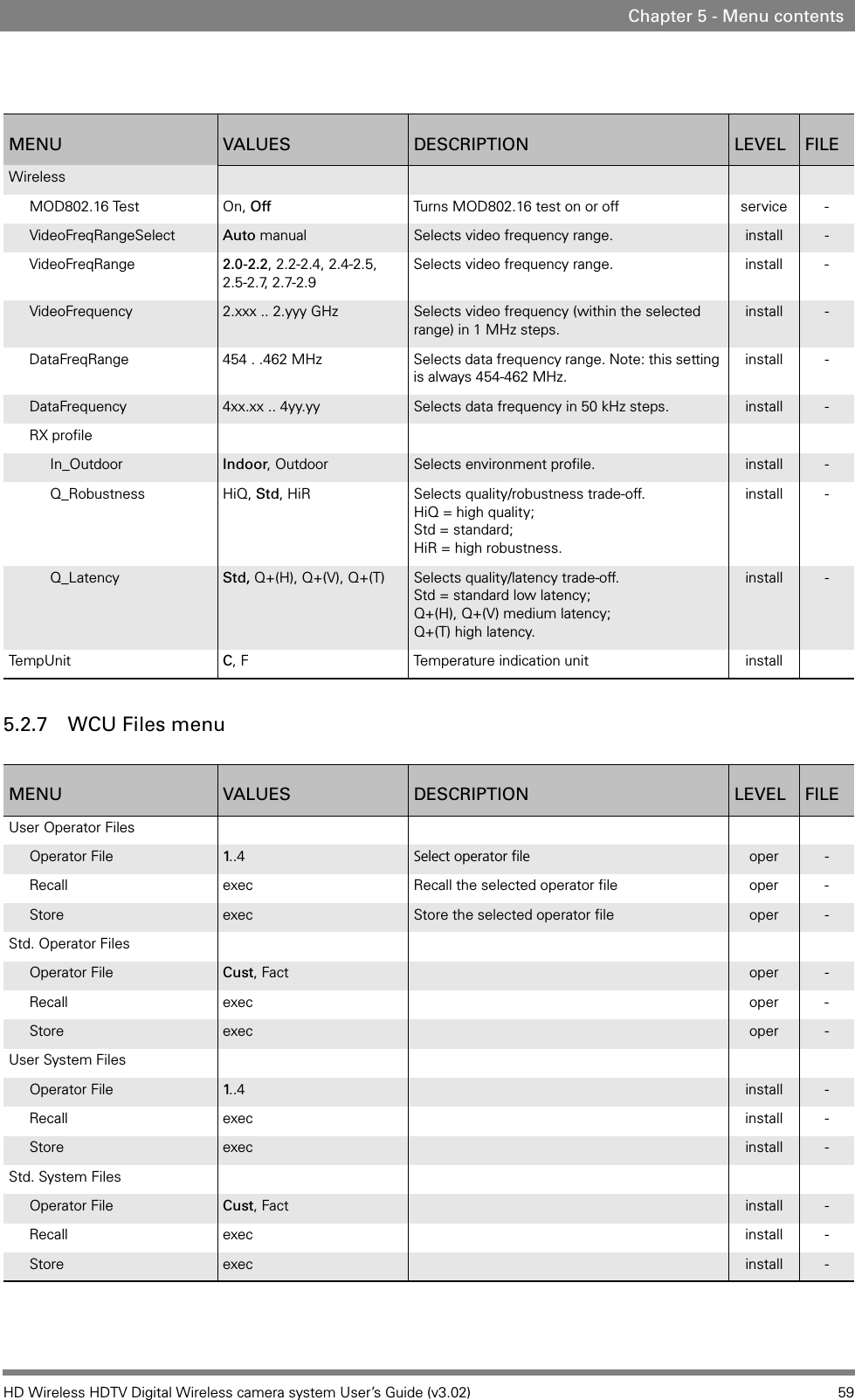
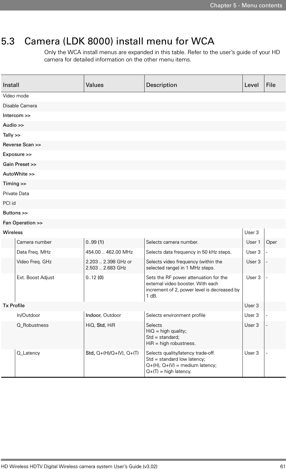
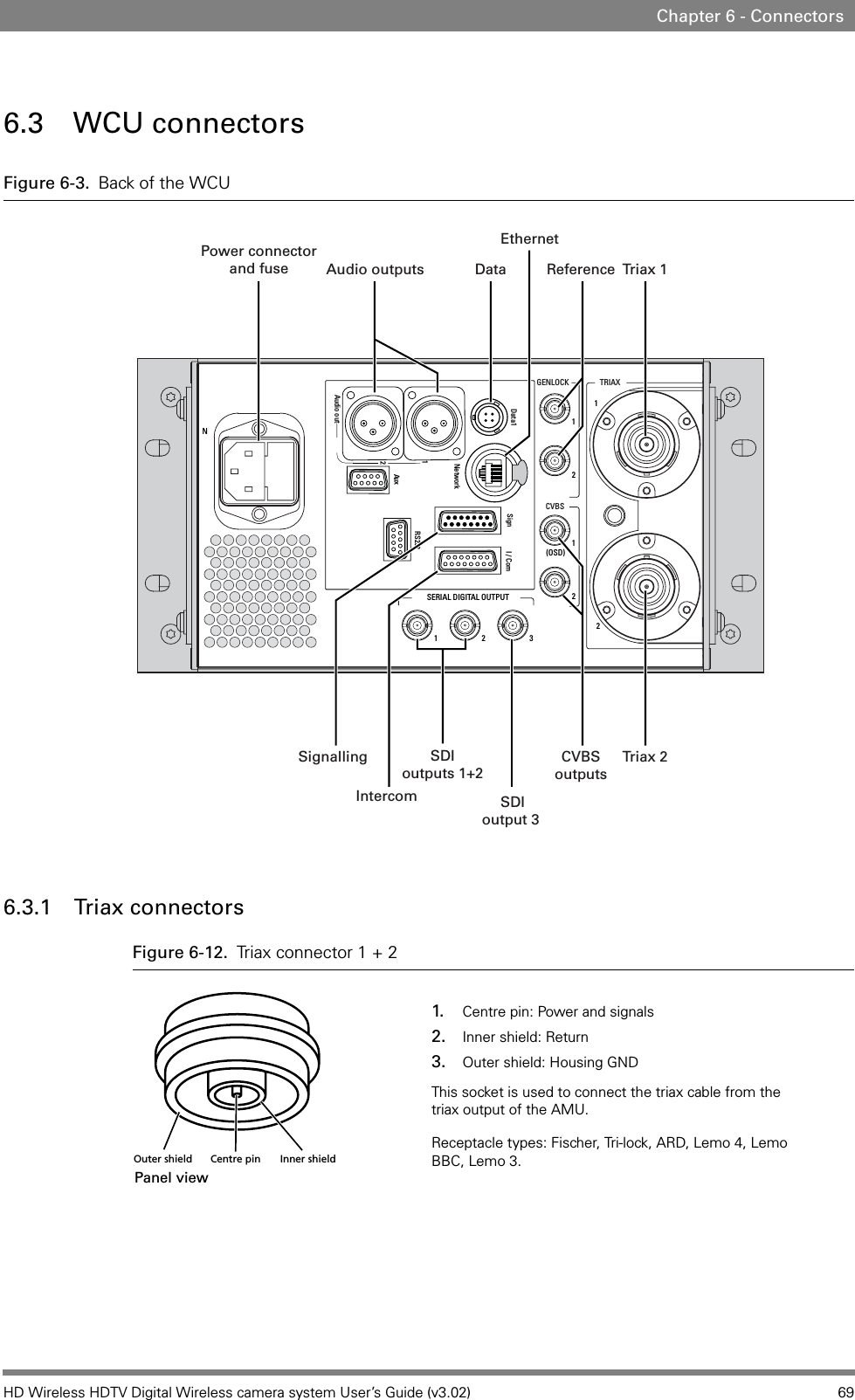
![60 HD Wireless HDTV Digital Wireless camera system User’s Guide (v3.02)Chapter 5 - Menu contents5.2.8 WCU Diagnostics menuMENU VALUES DESCRIPTION LEVEL FILEError Event loggingFatal software -service -Non-Fatal software - service -Unexpected software -service -Fatal System - service -Non-Fatal System -service -Erase All Erase Events - service -Board IDData Board [ID] oper -Board DiagnosticsData Board [value] oper -Communication DiagCamera connected exec oper -OCP connected exec oper -MCP connected exec oper -C2IP Panels exec oper -](https://usermanual.wiki/Thomson/GC801701/User-Guide-1164255-Page-60.png)