Thrane and Thrane A S 3711A Satellite Terminal User Manual E510
Thrane & Thrane A/S Satellite Terminal E510
UserManual.wiki
>
Thrane and Thrane A S
>
3711A User Manual
UserManual
Navigation menu
Upload a User Manual
Namespaces
Wiki Guide
HTML
PDF
Info
Views
User Manual
Discussion / Help
Navigation
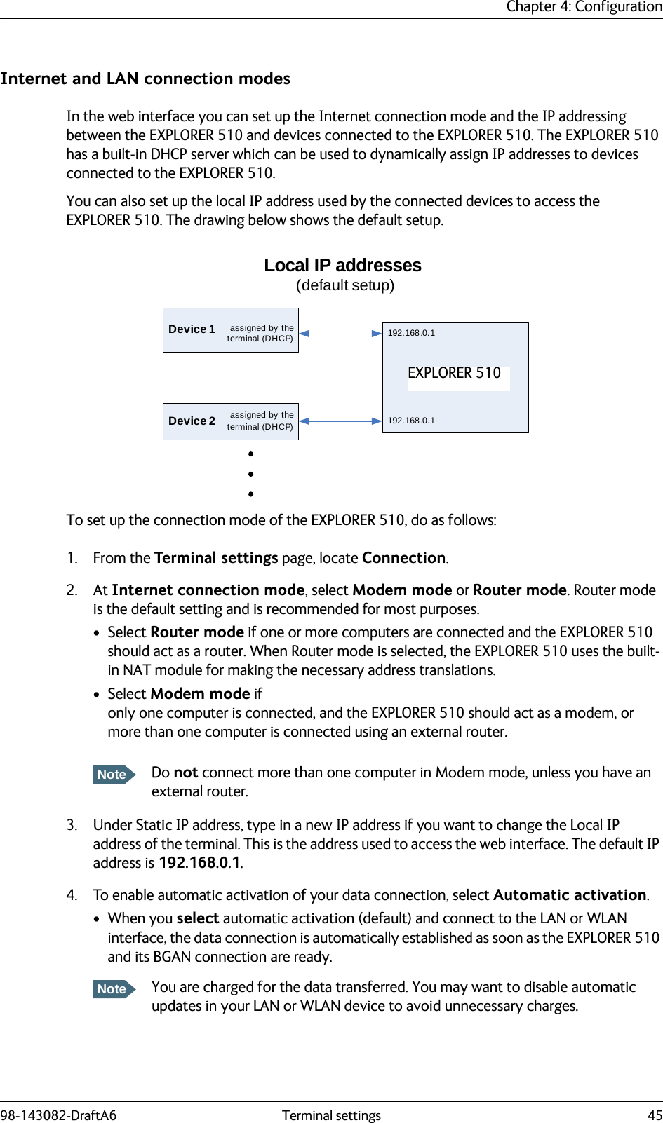
![98-143082-DraftA6 85Appendix BConformity BGeneralCE (R&TTE)The EXPLORER 510 is CE certified (R&TTE directive). The “Declaration of Conformity with R&TTE Directive” will be enclosed in electronic copy at the end of this appendix when ready.The WLAN interface is CE certified through the manufacturer of the WLAN card.Use of WLAN:The WLAN interface requires that the user enters the current country of operation. See WLAN interface setup on page 36.For use in the EU, the following restrictions apply:• France: Outdoor use must be limited to 10 mW EIRP within the frequency band 2454 MHz to 2483.5 MHz.• Italy: Outdoor use outside own premises require general authorization.ICThis device complies with Industry Canada licence-exempt RSS standard(s). Operation is subject to the following two conditions: (1) this device may not cause interference, and (2) this device must accept any interference, including interference that may cause undesired operation of the device.Le présent appareil est conforme aux CNR d'Industrie Canada applicables aux appareils radio exempts de licence. L'exploitation est autorisée aux deux conditions suivantes : (1) l'appareil ne doit pas produire de brouillage, et (2) l'utilisateur de l'appareil doit accepter tout brouillage radioélectrique subi, même si le brouillage est susceptible d'en compromettre le fonctionnement.This Class [B] digital apparatus complies with Canadian ICES-003.Cet appareil numérique de la classe [B] est conforme à la norme NMB-003 du Canada.FCCNote: This equipment has been tested and found to comply with the limits for a Class B digital device, pursuant to part 15 of the FCC Rules. These limits are designed to provide reasonable protection against harmful interference in a residential installation. This equipment generates, uses and can radiate radio frequency energy and, if not installed and used in accordance with the instructions, may cause harmful interference to radio communications. However, there is no guarantee that interference will not occur in a particular installation. If this equipment does](https://usermanual.wiki/Thrane-and-Thrane-A-S/3711A/User-Guide-2602977-Page-93.png)