Thrane and Thrane A S 6216 Sailor 6216 VHF Transceiver with DSC class D User Manual SAILOR6216UM
Thrane & Thrane A/S Sailor 6216 VHF Transceiver with DSC class D SAILOR6216UM
UserManual.wiki
>
Thrane and Thrane A S
>
6216 User Manual
manual
Navigation menu
Upload a User Manual
Namespaces
Wiki Guide
HTML
PDF
Info
Views
User Manual
Discussion / Help
Navigation

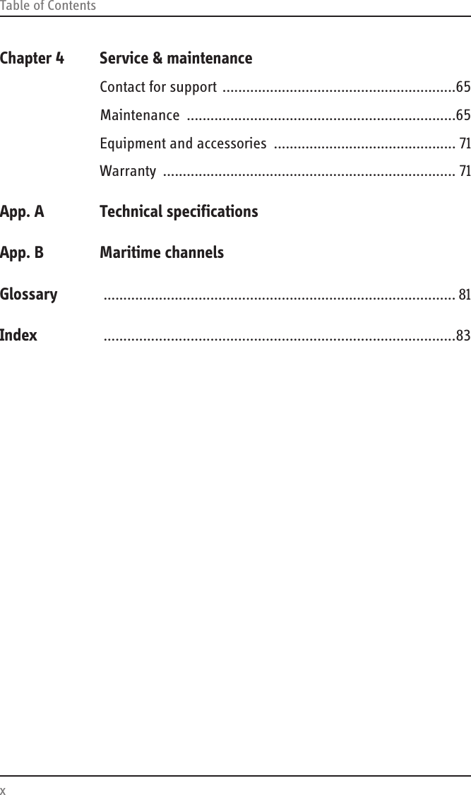
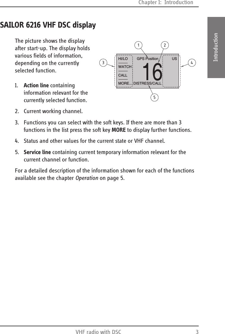


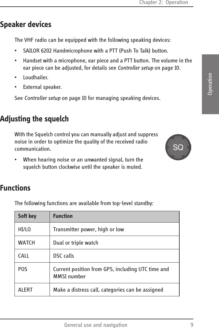
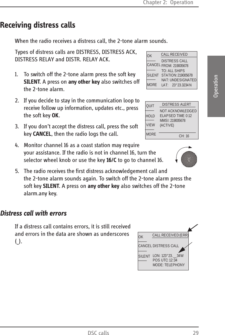
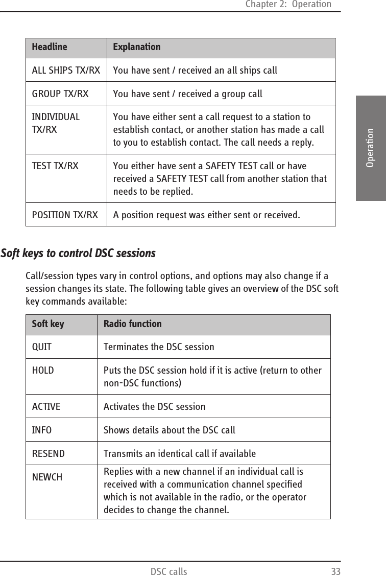
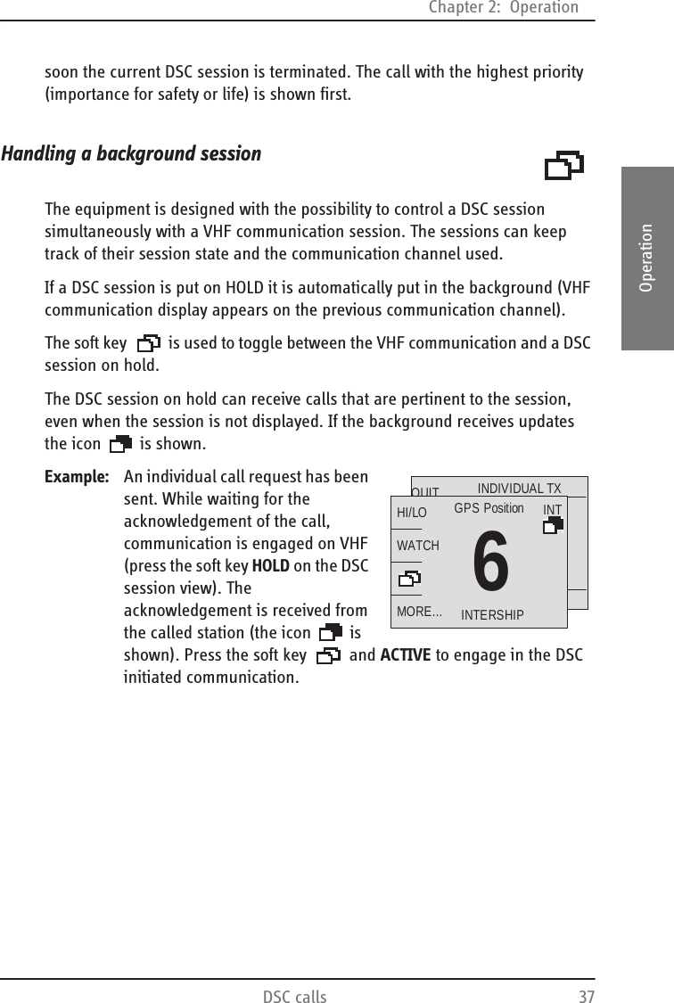
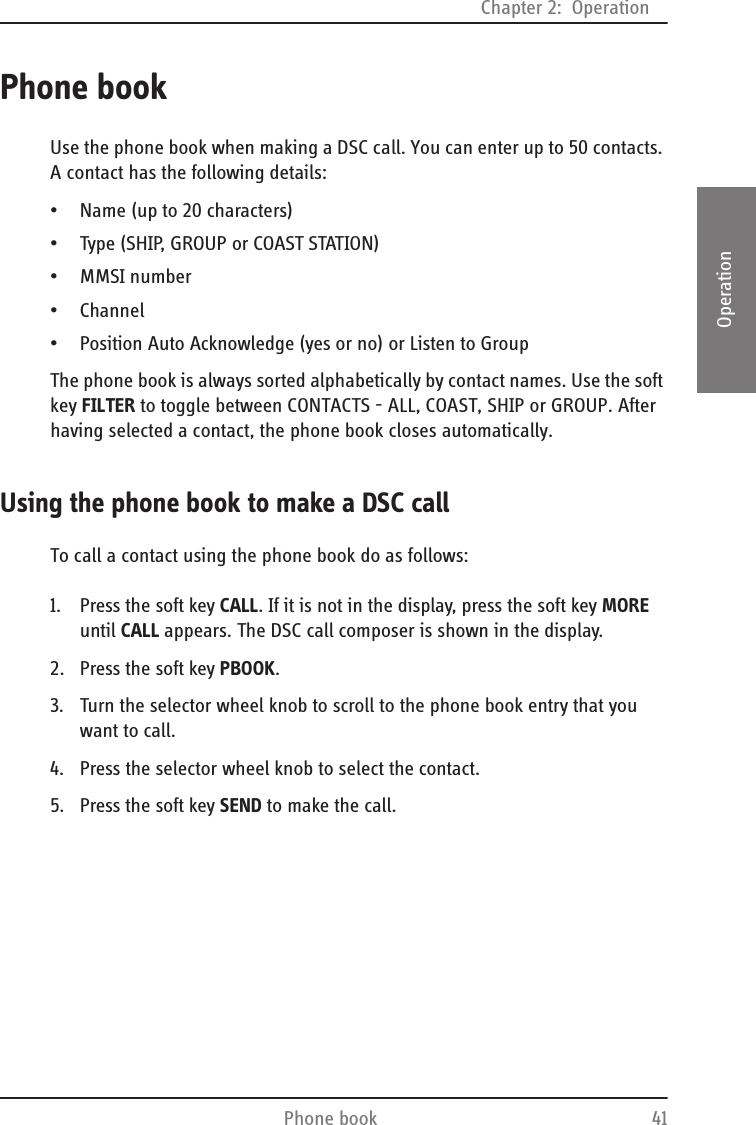
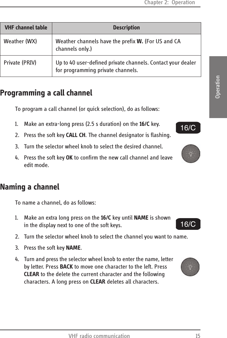
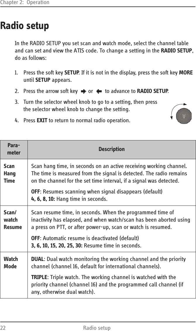
![Chapter 2: OperationVHF radio communication 132222OperationReceiving a radio telephone call on channel 16When you hear your call name in the loudspeaker, proceed as follows:1. An RX symbol shows that the radio is receiving on the working channel displayed.2. Lift the Handmicrophone or take the handset.3. Press the PTT key. A TX symbol shows that the radio is transmitting on the working channel displayed.4. Repeat the name of the station calling you and say: “This is [your ship’s name]”.5. Suggest a working channel other than 16 by saying: “Channel [suggested channel number]”.6. Say: “Over.” and release the PTT key to allow the caller to confirm the suggested new channel.7. Switch to the new channel by turning the selector wheel knob to the agreed channel and begin your conversation. Press PTT only when you are talking.Making a radio telephone call on channel 16To make a radio telephone call, proceed as follows:1. Select channel 16 by pressing the soft key 16/C or by turning the selector wheel knob.2. Lift the handset or take the Handmicrophone.3. Press the PTT key. A TX symbol shows that the VHF radio is transmitting on the working channel displayed.4. Say the name of the station you are calling three times.16HI/LOSCANCALLMORE...USGPS PositionDISTRESS/CALLRX16HI/LOSCANCALLMORE...USGPS PositionDISTRESS/CALLTX16HI/LOSCANCALLMORE...USGPS PositionDISTRESS/CALLTX](https://usermanual.wiki/Thrane-and-Thrane-A-S/6216/User-Guide-1246254-Page-25.png)
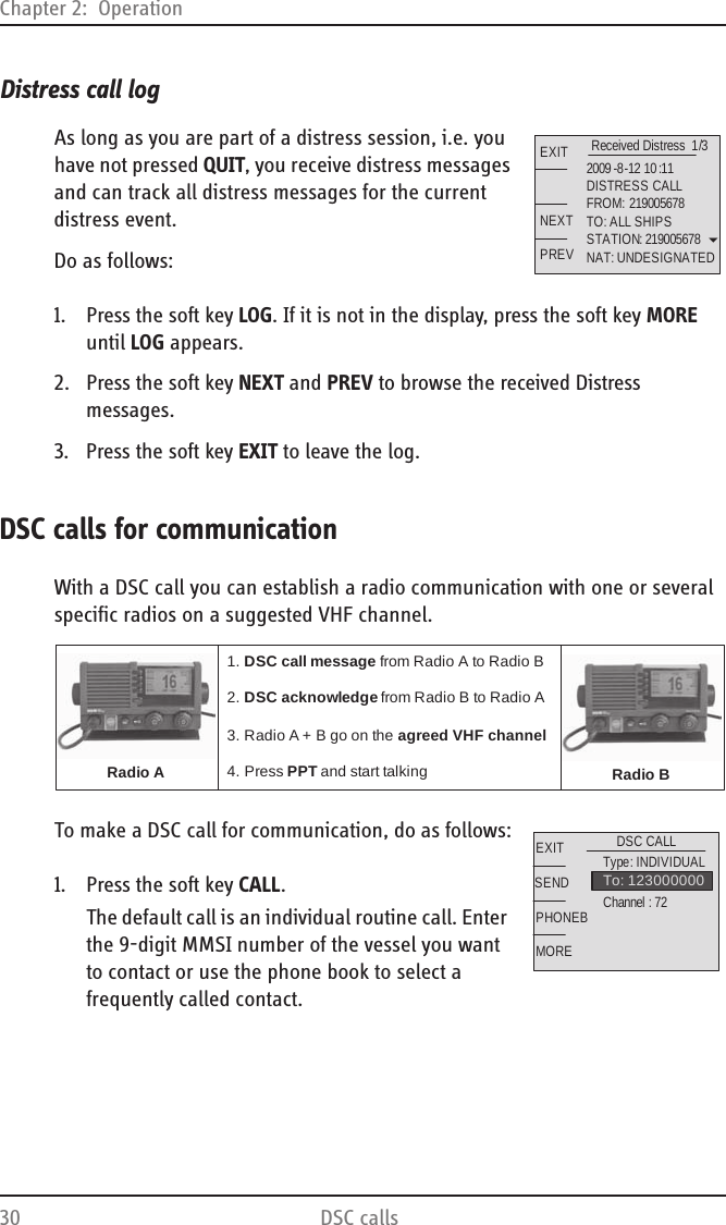
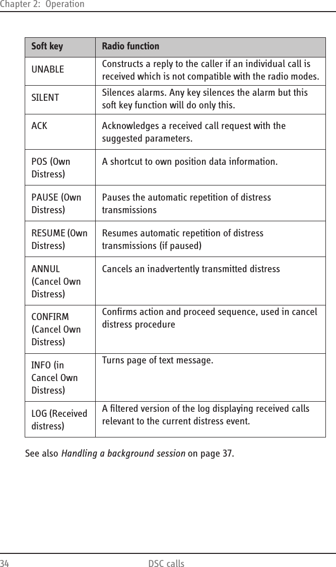
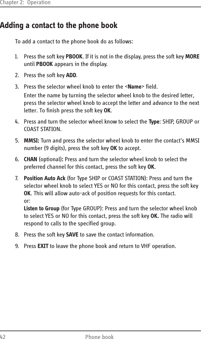
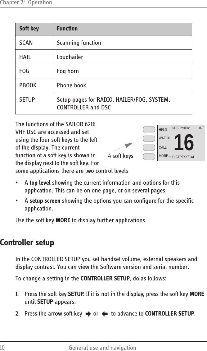
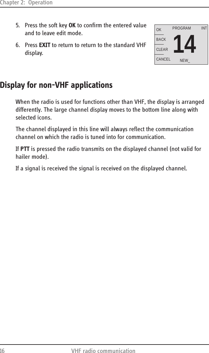
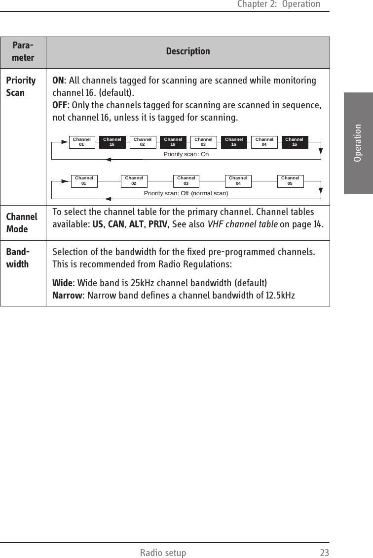
![Chapter 2: Operation14 VHF radio communication5. Say: “This is [your ship’s name]”.6. Say: “Over.” and release the PTT key to listen. An RX symbol shows that the radio is receiving on the working channel displayed7. When answered, agree upon a working channel other than 16.8. Switch to the new channel by turning the selector wheel knob to the agreed channel and begin your conversation.VHF channelsYou can change channels whenever the channel designator is displayed. Turn the selector wheel knob to browse through all channels that are available in the selected channel mode. The channels appear in the display in the following order:• Primary channels• Weather channels (if any)• Private channels (if any)To quickly toggle between these 3 channel groups make a long press and release the selector wheel knob. The VHF radio toggles between the last selected channels in the respective groups, i.e. the last selected weather channel, the last selected private channel or the last selected primary channel. If there are no channels defined in a group, it is not selected.16HI/LOSCANCALLMORE...USGPS PositionDISTRESS/CALLRX6HI/LOSCANCALLMORE... INTERSHIPINTGPS PositionW2HI/LOSCANCALLMORE...USGPS PositionP2HI/LOSCANCALLMORE...INTGPS PositionVHF channel table DescriptionPrimary channels (no prefix)For details see Maritime channels on page 75.For instructions how to change a channel table see Radio setup on page 22.](https://usermanual.wiki/Thrane-and-Thrane-A-S/6216/User-Guide-1246254-Page-26.png)
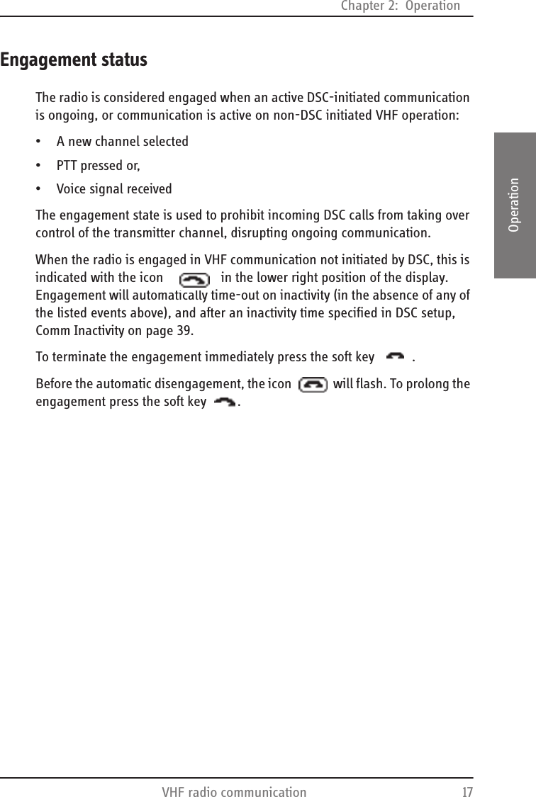
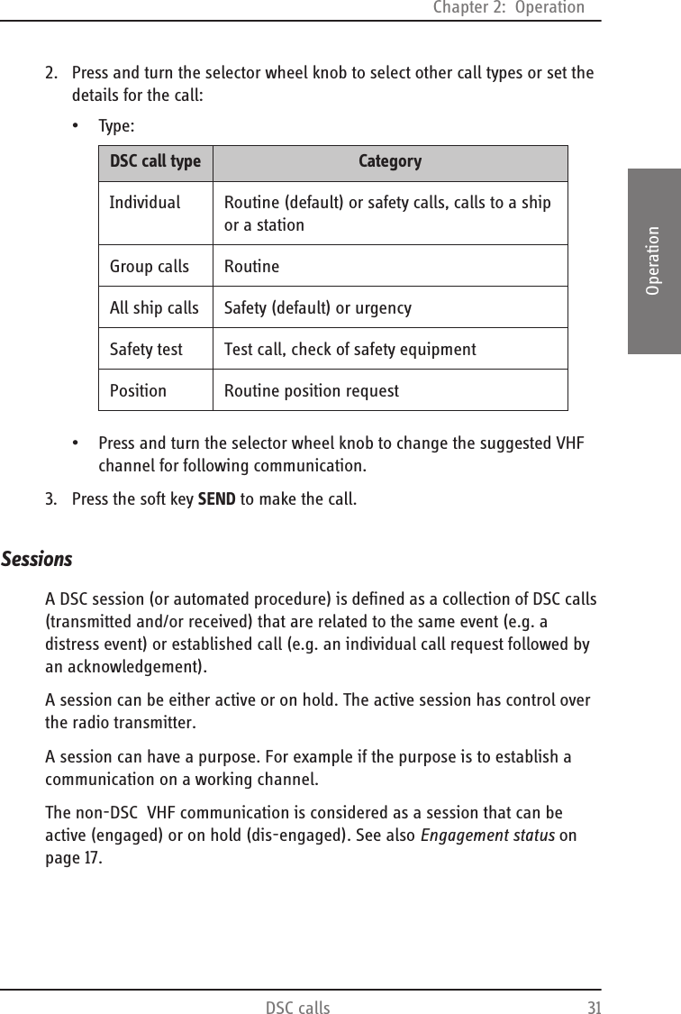
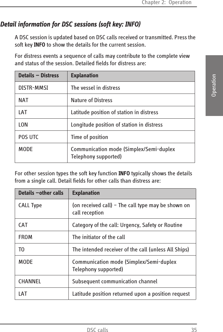
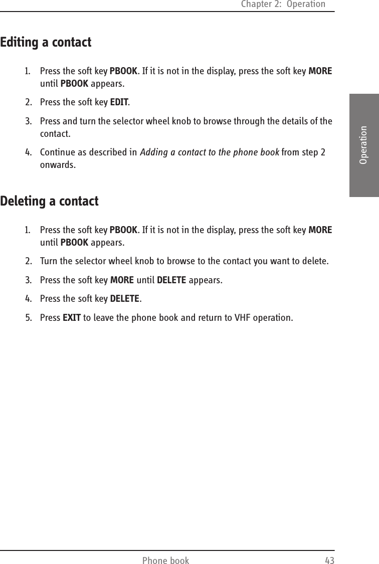
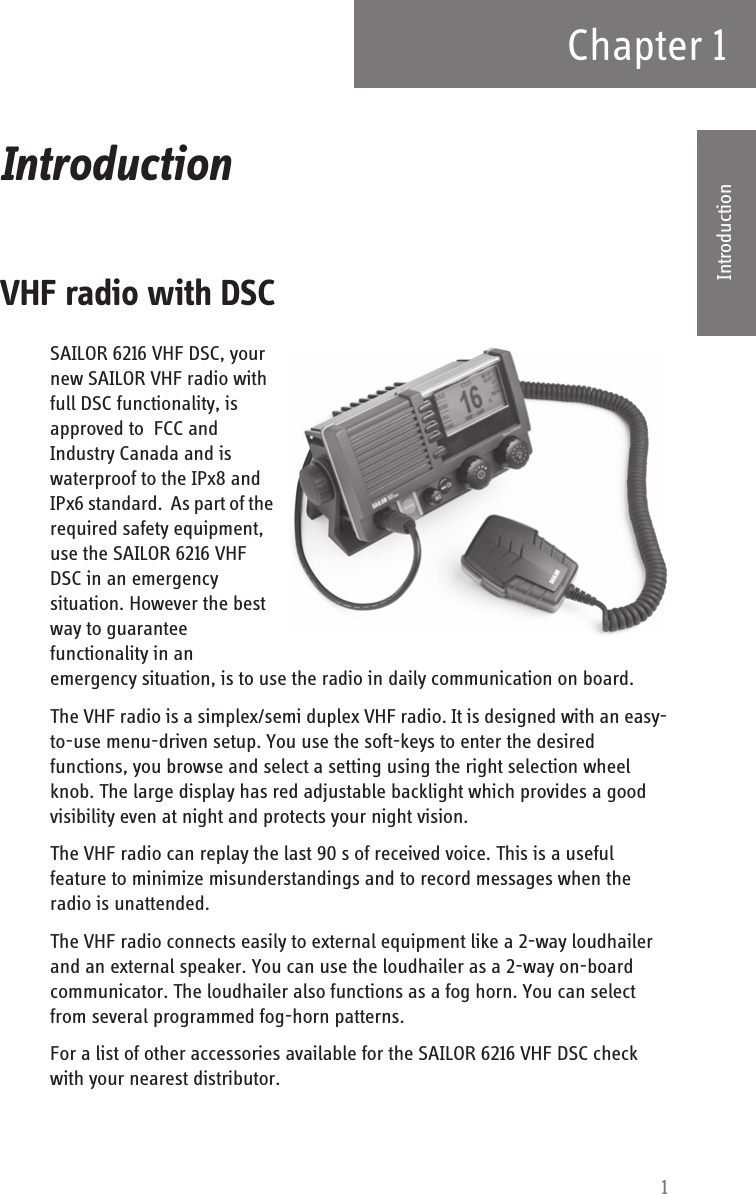
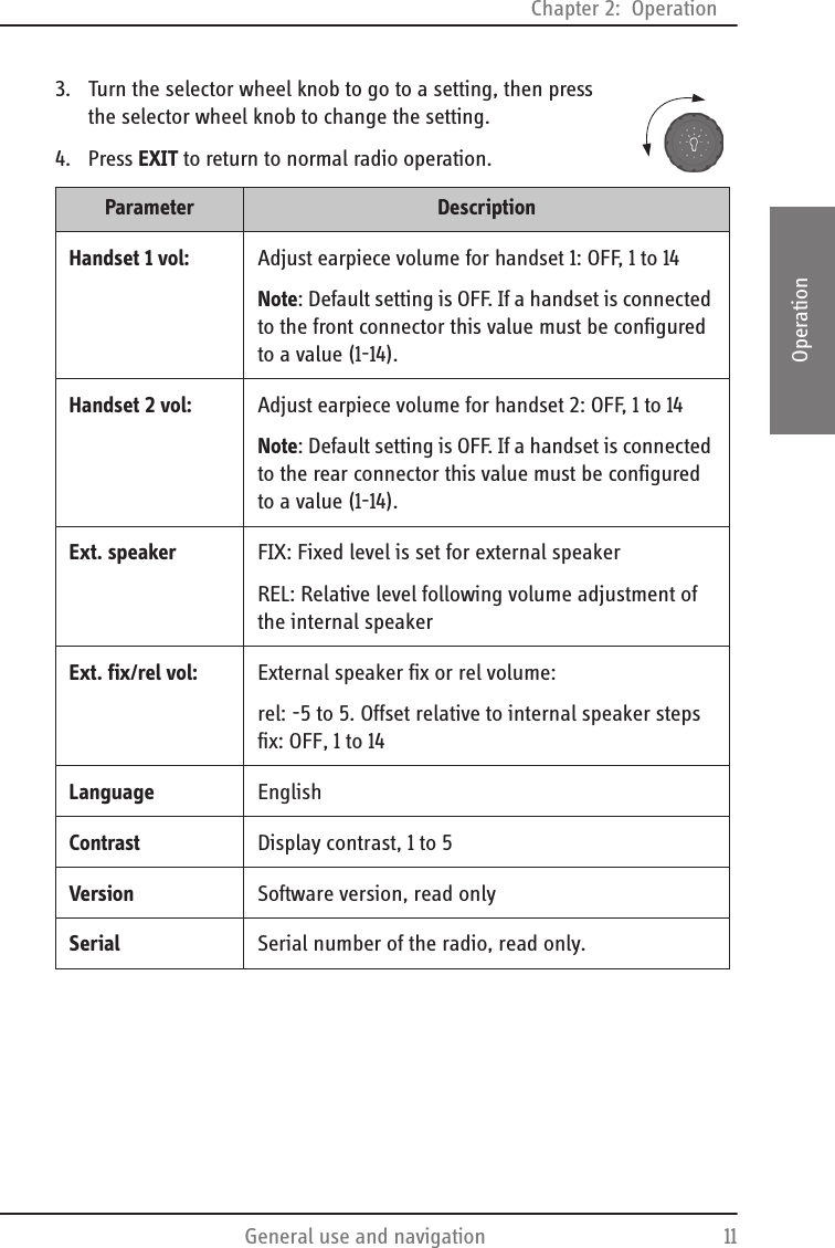
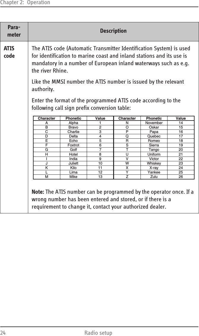
![Chapter 2: OperationWatch 192222OperationWatchThe SAILOR 6216 VHF DSC radio can be set to dual watch or triple watch. In dual watch, the working channel and channel 16 are watched. In triple watch the working channel, channel 16 and the programmed call channel are watched.You can select the working channel in any watch mode by turning the selector wheel knob. The working channel that is displayed is the channel used for dual or triple watch. If there is a signal in one of the watched channels and squelch opens, the display shows the channel in which the signal is received.Using WATCH1. To start watch press the soft key WATCH. The radio enters the last watch mode. It is displayed in the action line.2. To stop WATCH press WATCH again, or press PTT on the speaking device.For instructions how to change between DUAL and TRIPLE WATCH see Radio setup on page 22.NoteIf PTT is operated during any watch mode. the WATCH function is terminated and you transmit on the displayed channel. Watch mode may be resumed after releasing the PTT button if the scan resume time is set up in SETUP, for instructions see Radio setup on page 22.16916924Dual watch Triple watchWorking channel + channel 16 Working channel + channel 16+ call channel6HI/LO[9]+[16]TRIWATCHWATCHINTMORE...SCAN](https://usermanual.wiki/Thrane-and-Thrane-A-S/6216/User-Guide-1246254-Page-31.png)
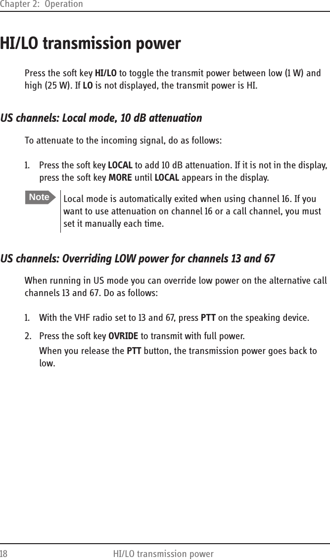
![Chapter 2: Operation20 ScanScanThe radio has a scanning function for tagged channels. Any available channel, including weather and private channels, can be tagged and added to the scanning sequence. As default the radio scans with priority scanning of channel 16. If a signal is received while in any scanning mode, only channel 16 continues to be watched.If there is a signal in one of the scanned channels, the display shows the channel in which the signal is received. Pressing PTT while a signal is received stops scanning and the radio is tuned into the displayed channel.Using SCAN1. To start scanning press the soft key SCAN. The SCAN menu is shown. Press START to start scanning.2. To stop SCAN press SC STOP, or press PTT on the speaking device.3. To tag a channel to include in the scanning sequence turn the selector wheel knob until the wanted channel is in the display. Then press the soft key TAG. The display shows the channel number and the word TAG at the right side of the display.4. To remove a channel from the scanning sequence, turn the selector wheel knob until the tagged channel is displayed. Then press the soft key TAG to remove the tag.When scanning is activated the working channel is displayed in a different format (open). This indicates the radio is not tuned into the displayed channel. The displayed working channel is temporarily included in the scanning list (although no TAG icon is shown).If PTT is pressed while scanning, the scanning is stopped and transmission starts immediately on the displayed working channel.EXITTAG[TAG]+[16]PRIORITY SCANTAGSTOPSC](https://usermanual.wiki/Thrane-and-Thrane-A-S/6216/User-Guide-1246254-Page-32.png)
![Chapter 2: OperationScan 212222OperationUS channels: Watch alarms for NOAA Weather alertsYou can turn on or off an independent watch alarm for a specific weather channel.To turn on or off an independent NOAA weather alarm do as follows:1. In the SCAN menu, turn the selector wheel knob to select a specific weather channel.2. Press the soft key WX to tag this weather channel for NOAA weather alert.3. On the display you can see that the selected weather channel alert watch is enabled. In this example it is [W2].The weather channel set-up for the alarm is scanned frequently during scanning, watch or when the radio is not operated or receiving on a working channel. 4. If a NOAA weather alert is detected on a weather channel, beep tones are presented and a pop-up window is displayed. Press YES to switch to the weather channel.NoteNOAA weather channels are available in the waters of USA and Canada only.W2EXIT[TAG]+[16]PRIORITY SCANSC STOP [W2]WXTAGYES WEATHER ALERTNOAA WEATHER ALERT. SWITCH TO WEATHER CHANNEL?NOWEATHER ALERT](https://usermanual.wiki/Thrane-and-Thrane-A-S/6216/User-Guide-1246254-Page-33.png)
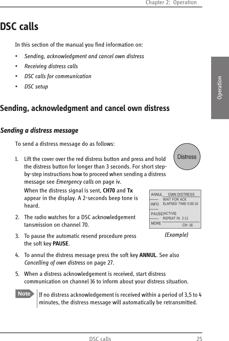
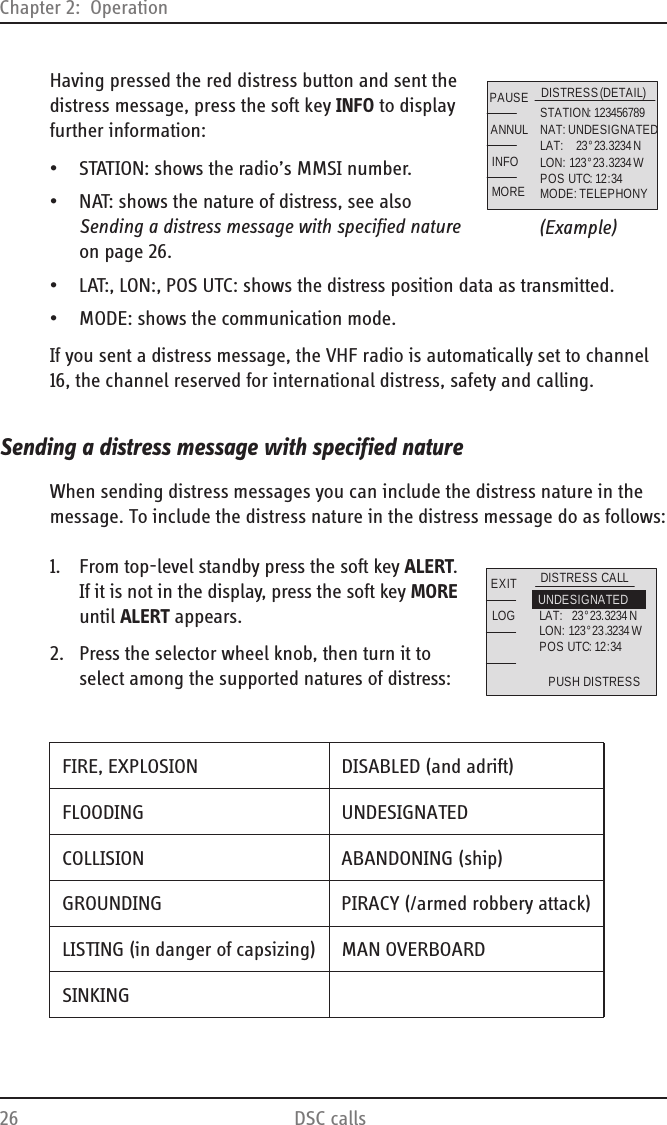
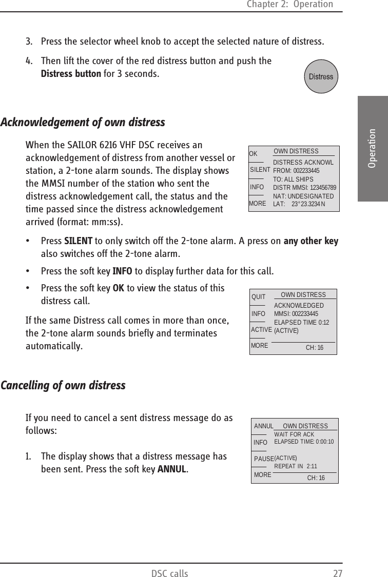
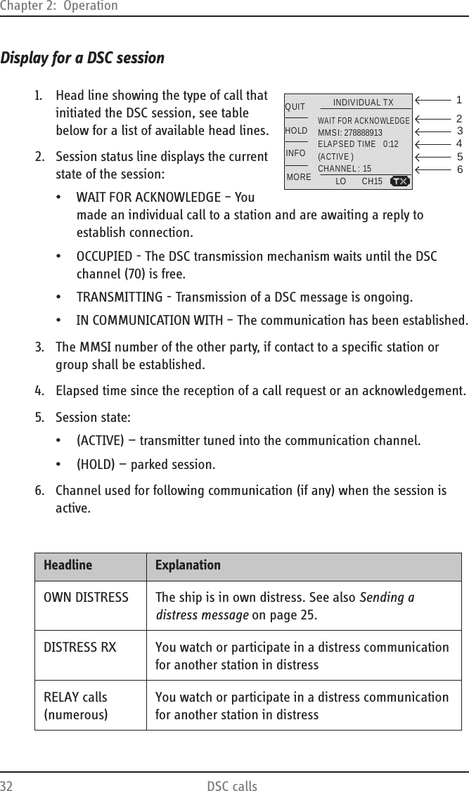
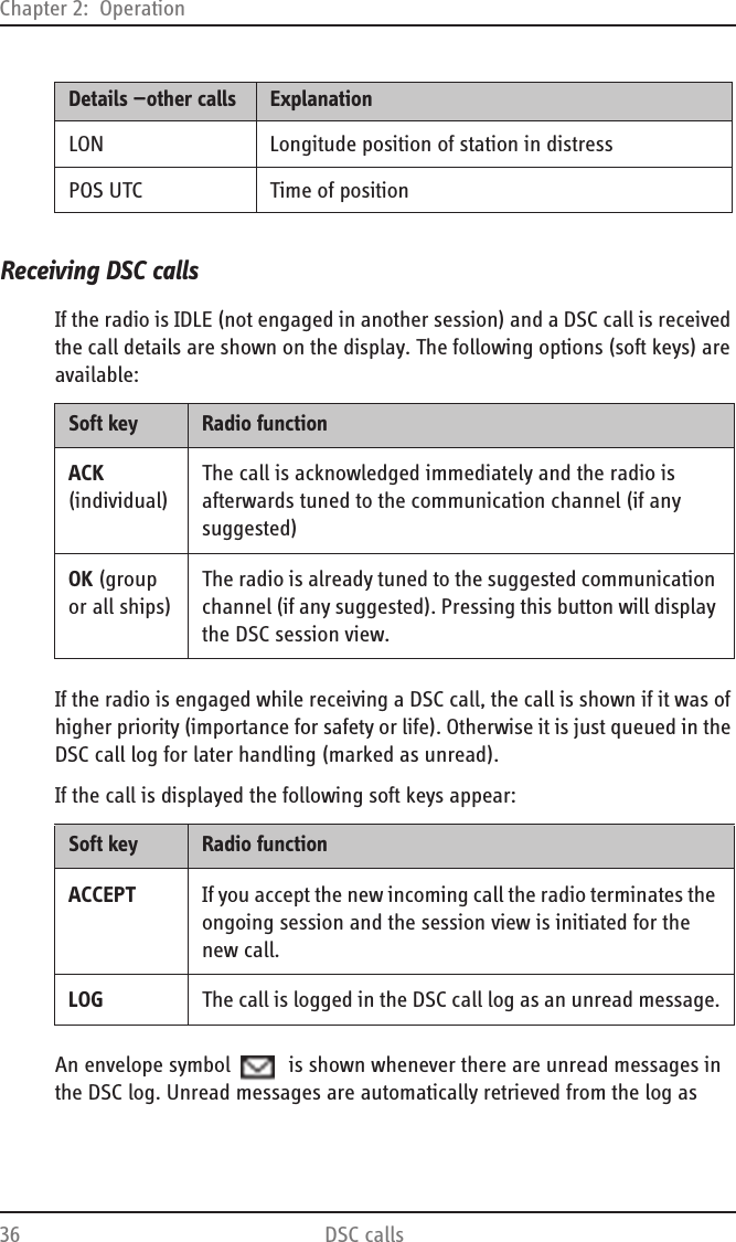
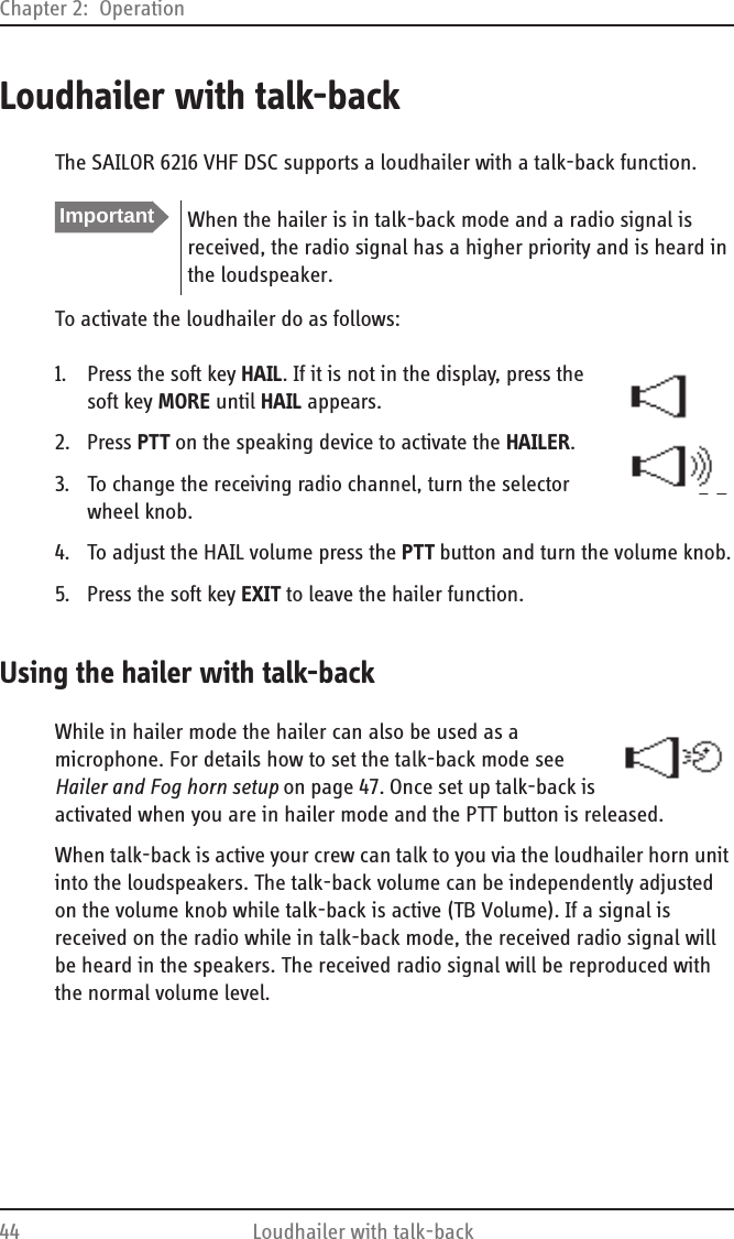
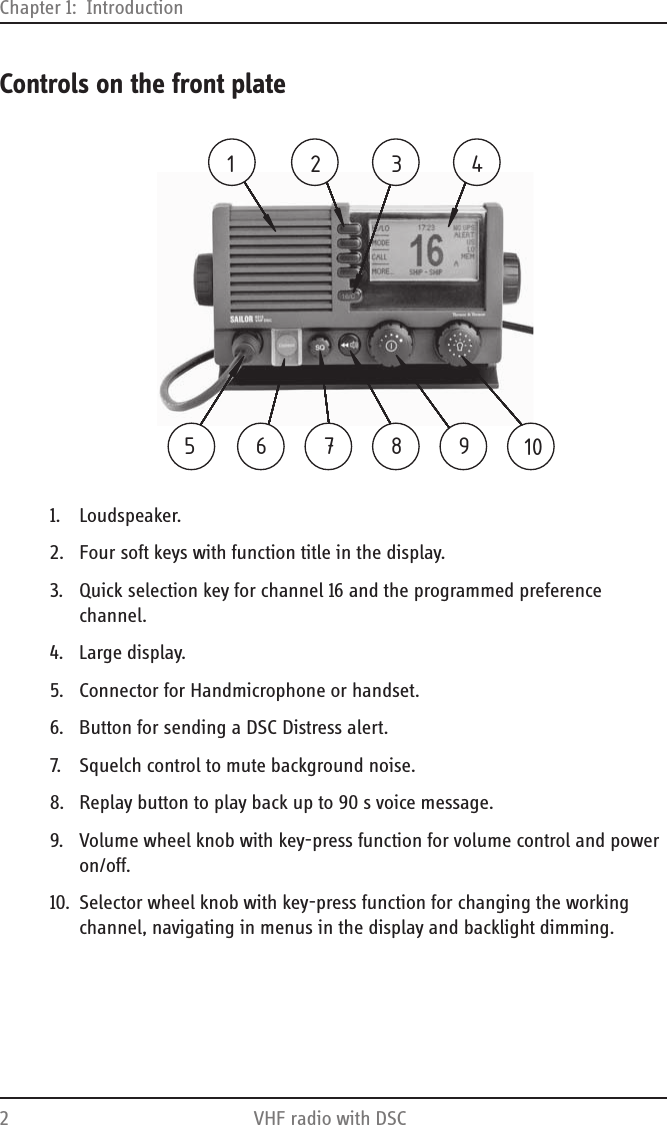
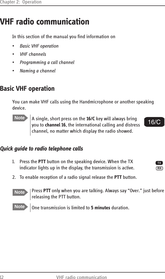
![Chapter 2: Operation28 DSC calls2. Press the soft key YES to go ahead with the cancelling process. At this stage you have the option to press the soft key NO to return to distress sending procedure.3. The SAILOR 6216 VHF DSC will send the Self- cancellation call on channel 70 and the display automatically shows the message that you should say when cancelling the distress with a radio message.4. Press the soft key INFO to scroll to the next display to proceed with the voice cancel5. Press the soft key OK to go to the acknowledged state. Own distress is cancelled now.Power failure while in distressIn case of a power failure or switch-off during the transmission of a Distress the SAILOR 6216 VHF DSC gives an audible warning after power-up and automatically resumes sending Distress 10 seconds after power up.Within the 10 seconds you have the following options:•Press QUIT to terminate the active distress procedure (acknowledged or unacknowledged)•Press CONFIRM (or do nothing) to resume the sending Distress procedure.YESNO DO YOU WANT TOCANCEL YOUROWN DISTRESS?WARNINGOWN DISTRESS-- TRANSMITTING –CANCEL DISTRESSPREPARE FOR VOICE CANCELCH: 70OKINFOHI/LOSETUPTXVOICE CANCEL”All stations, All stations, All stations This is [vessel name 3 times]. Our MMSI number is 123456789 .” OKTXVOICE CANCELOur position is latitude 23°23.3234 N, longitude123 °23.3234 WCANCEL our Distress Alert of 12:34 hours”OKTXMY DISTRESS16WAITING FOR REPLYELAPSED TIME 6:16(ACTIVE)REPEAT IN 2:11RESUME SENDING DISTRESS IN8 SECONDSWARNINGQUITCONFIRM](https://usermanual.wiki/Thrane-and-Thrane-A-S/6216/User-Guide-1246254-Page-40.png)