Thrane and Thrane A S AERO-HSU Aeronautical Satellite Telephone User Manual 98 113625 d
Thrane & Thrane A/S Aeronautical Satellite Telephone 98 113625 d
UserManual.wiki
>
Thrane and Thrane A S
>
AERO HSU User Manual
users manual
Navigation menu
Upload a User Manual
Namespaces
Wiki Guide
HTML
PDF
Info
Views
User Manual
Discussion / Help
Navigation
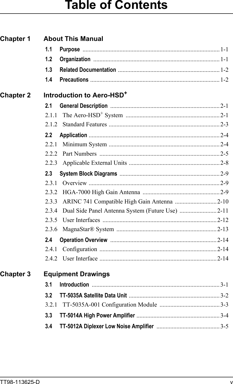
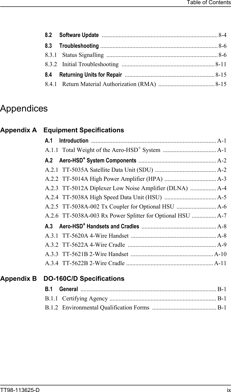
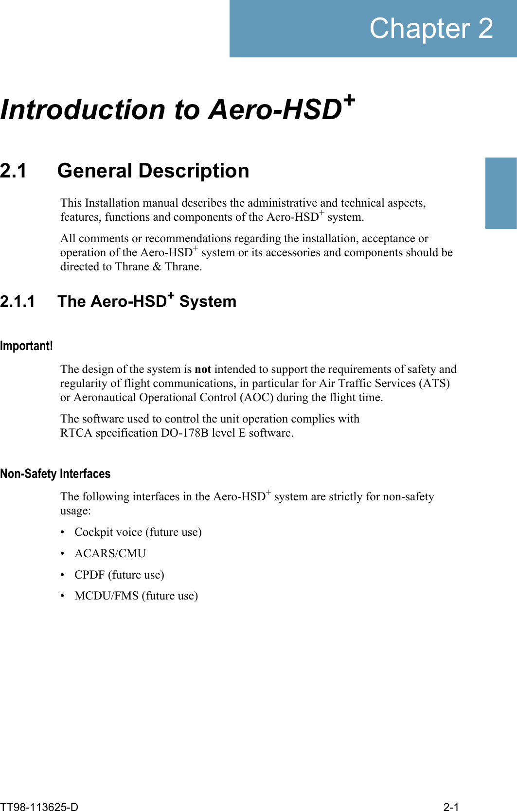

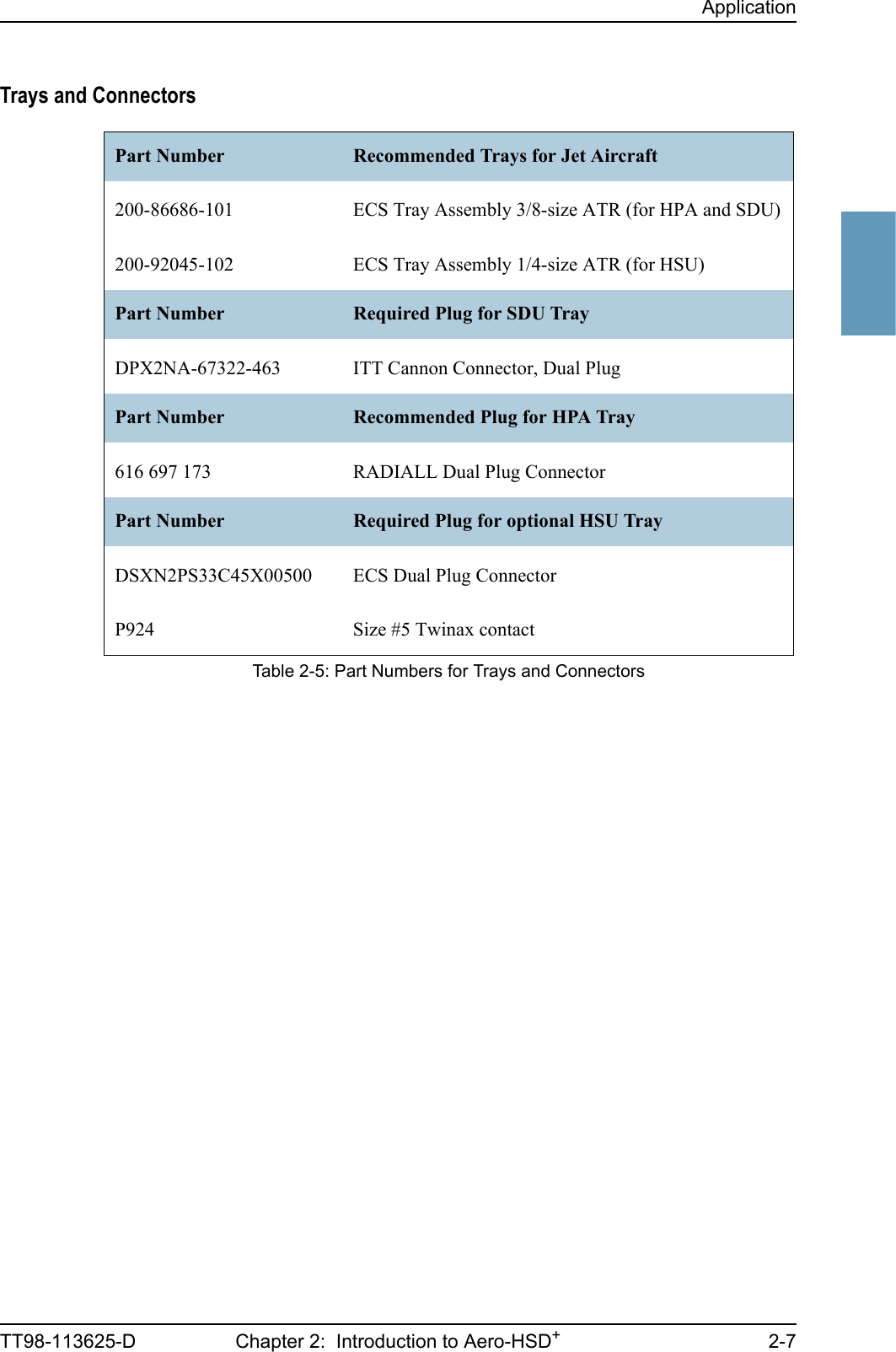
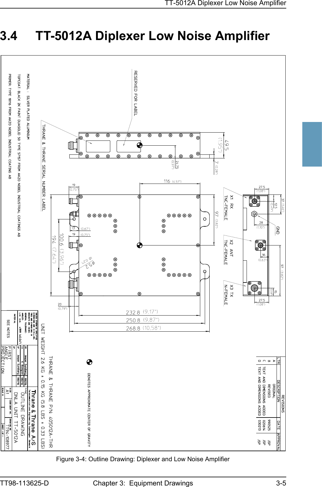
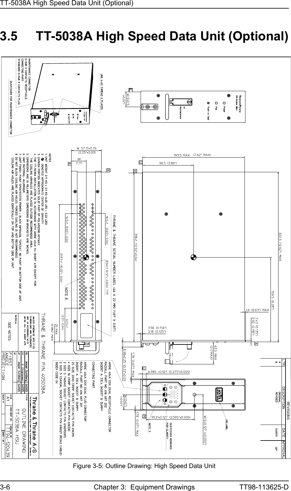
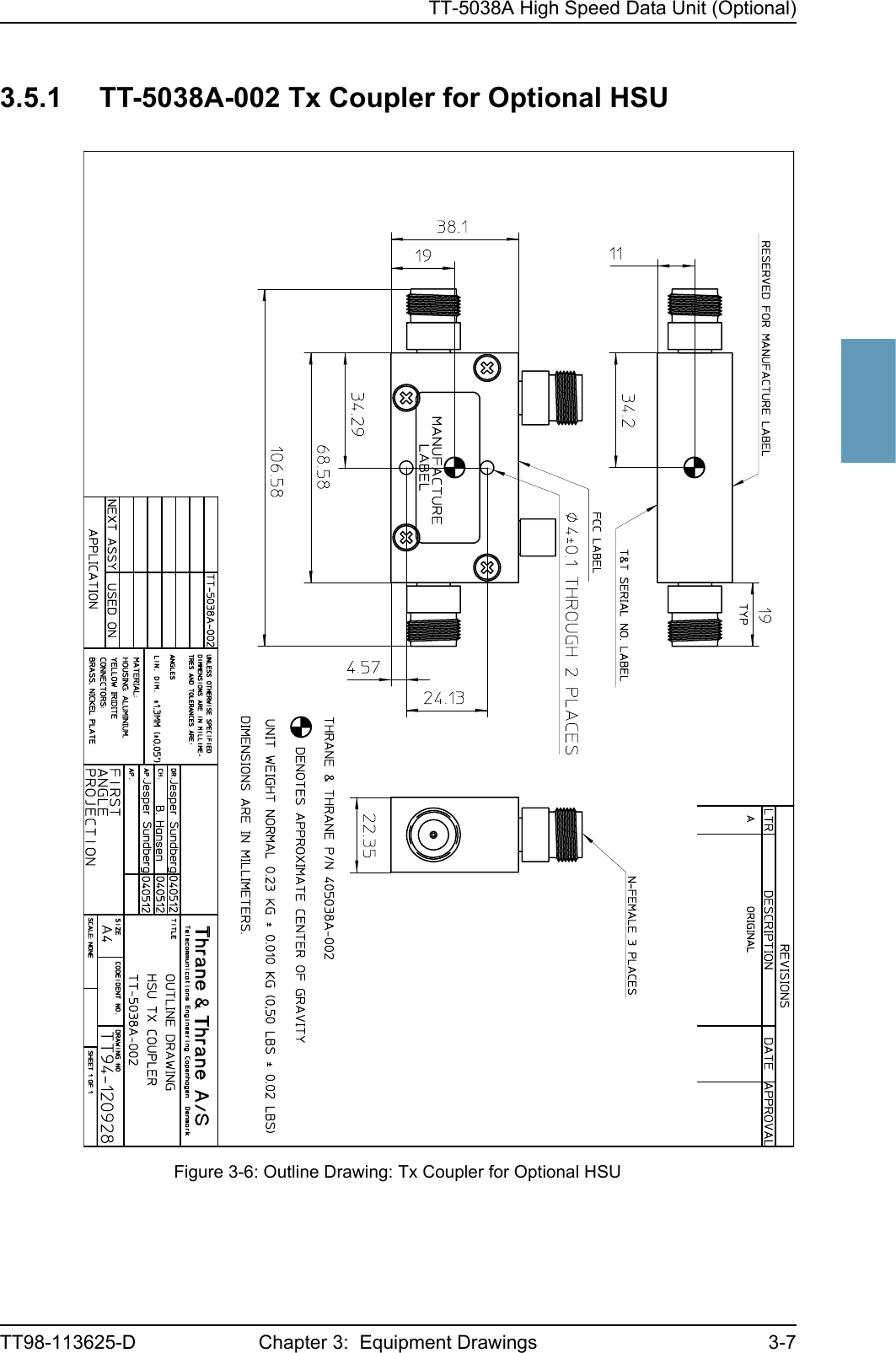
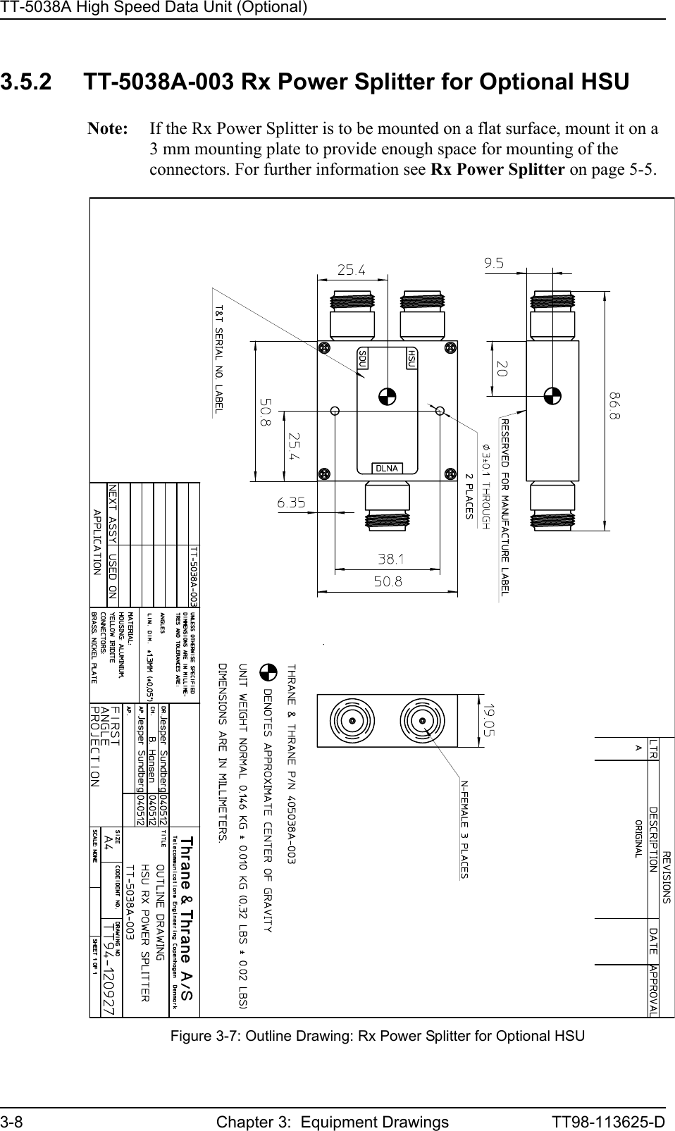
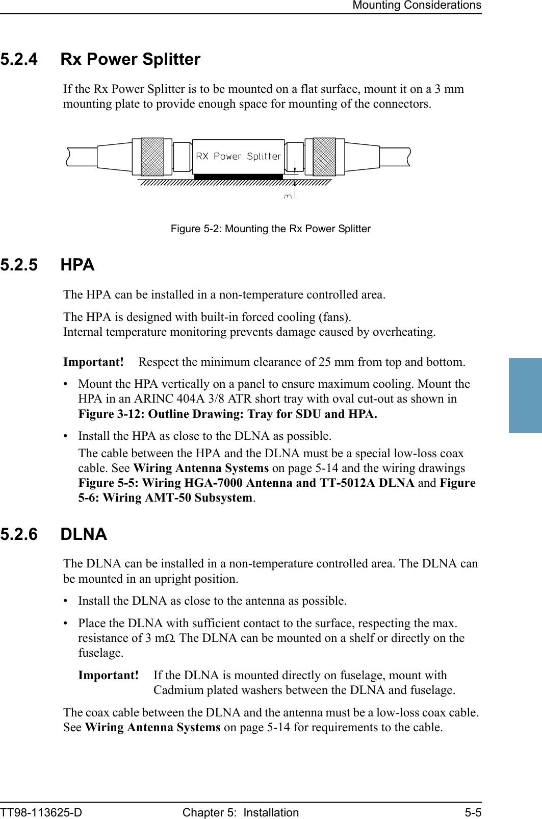
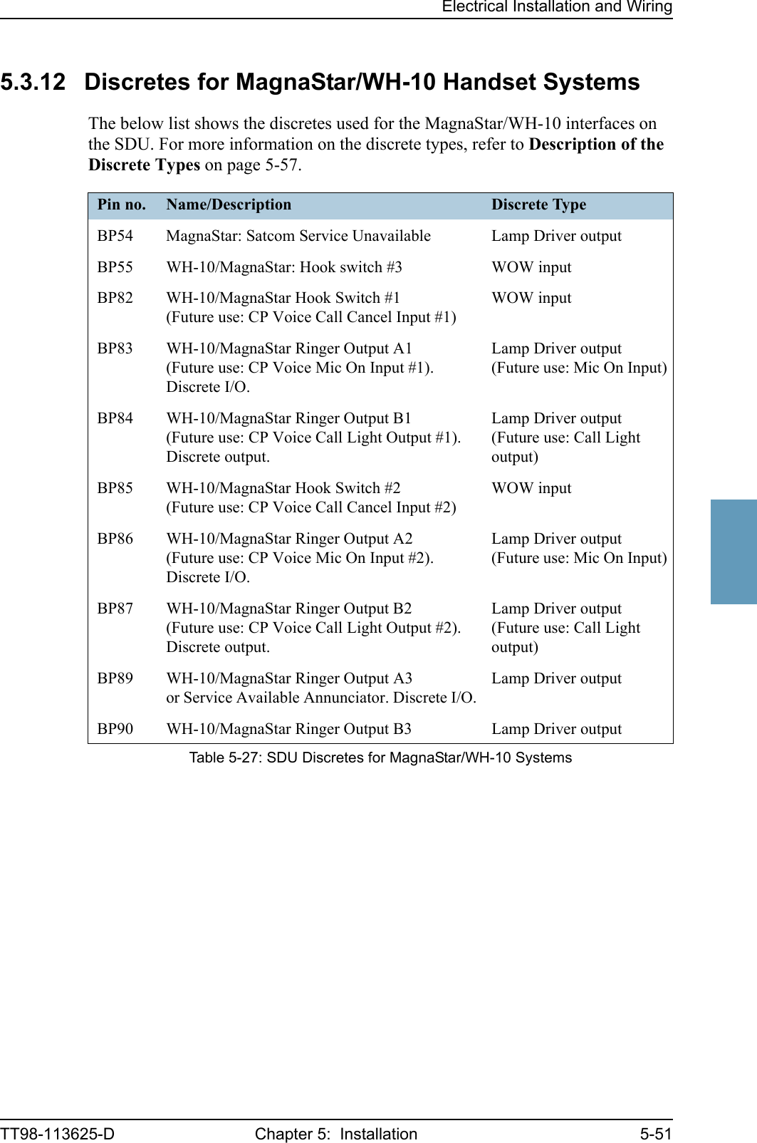
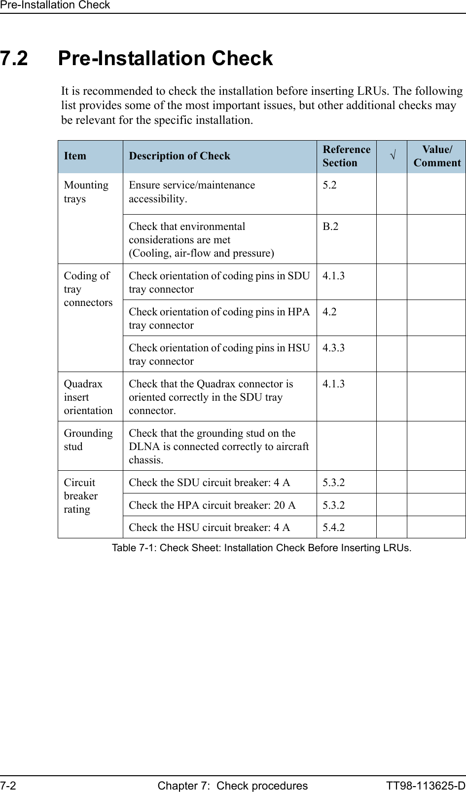
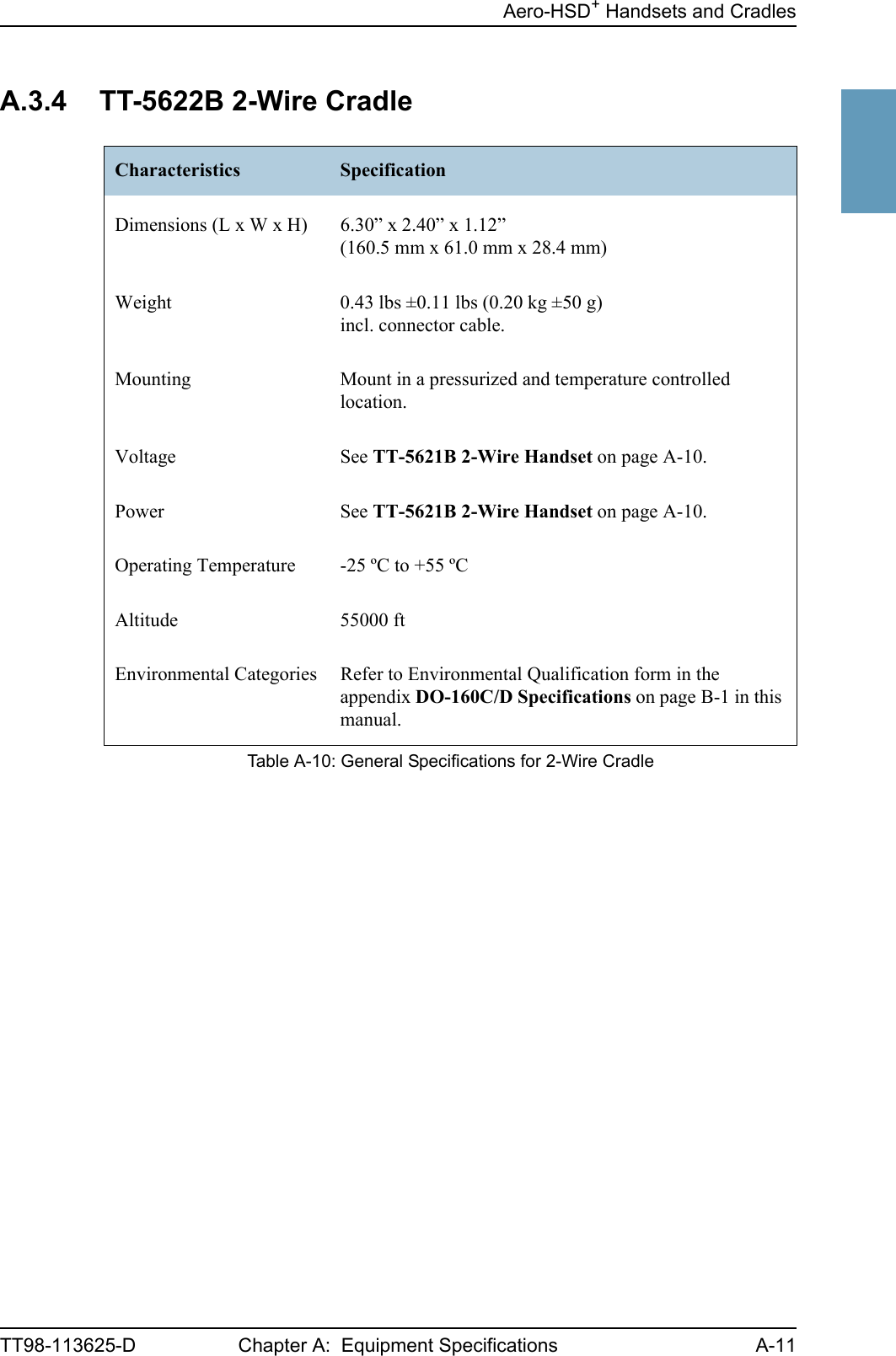
![ApplicationTT98-113625-D Chapter 2: Introduction to Aero-HSD+2-522222.2.2 Part NumbersApplicable Thrane & Thrane Model- and Part NumbersThis Installation Manual is for the Aero-HSD+ system and is applicable to the model- and part numbers below:T&T Part Number Model Number Description405035A TT-5035A Satellite Data Unit (SDU) [without CM]405035A-001 TT-5035A-001 Configuration Module (CM)405038A TT-5038A High Speed data Unit (HSU). Additional Swift64 channel for a total of 128 kbit/s (optional)405038A-002 TT-5038A-002 HSU Tx Coupler (optional)405038A-003 TT-5038A-003 HSU Rx Power Splitter (optional)405014A TT-5014A High Power Amplifier (HPA)405012A-THR TT-5012A Diplexer / Low Noise Amplifier (DLNA)405620A-THW TT-5620A 4-Wire Handset (white)405620A-THR TT-5620A 4-Wire Handset (black)405622A-THW TT-5622A 4-Wire Cradle (white)405622A-THR TT-5622A 4-Wire Cradle (black)405621B-THW TT-5621B 2-Wire Handset (white)405621B-THR TT-5621B 2-Wire Handset (black)405622B-THW TT-5622B 2-Wire Cradle (white)405622B-THR TT-5622B 2-Wire Cradle (black)TT 37-112940 Maintenance Cable (SDU Front Connector Maintenance via PC)TT 83-119958 CD with HSD+ Configuration ProgramTable 2-1: Model and Part Numbers for the Aero-HSD+ System (T&T Units)](https://usermanual.wiki/Thrane-and-Thrane-A-S/AERO-HSU/User-Guide-507698-Page-25.png)
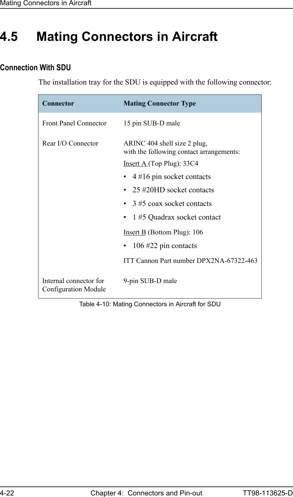
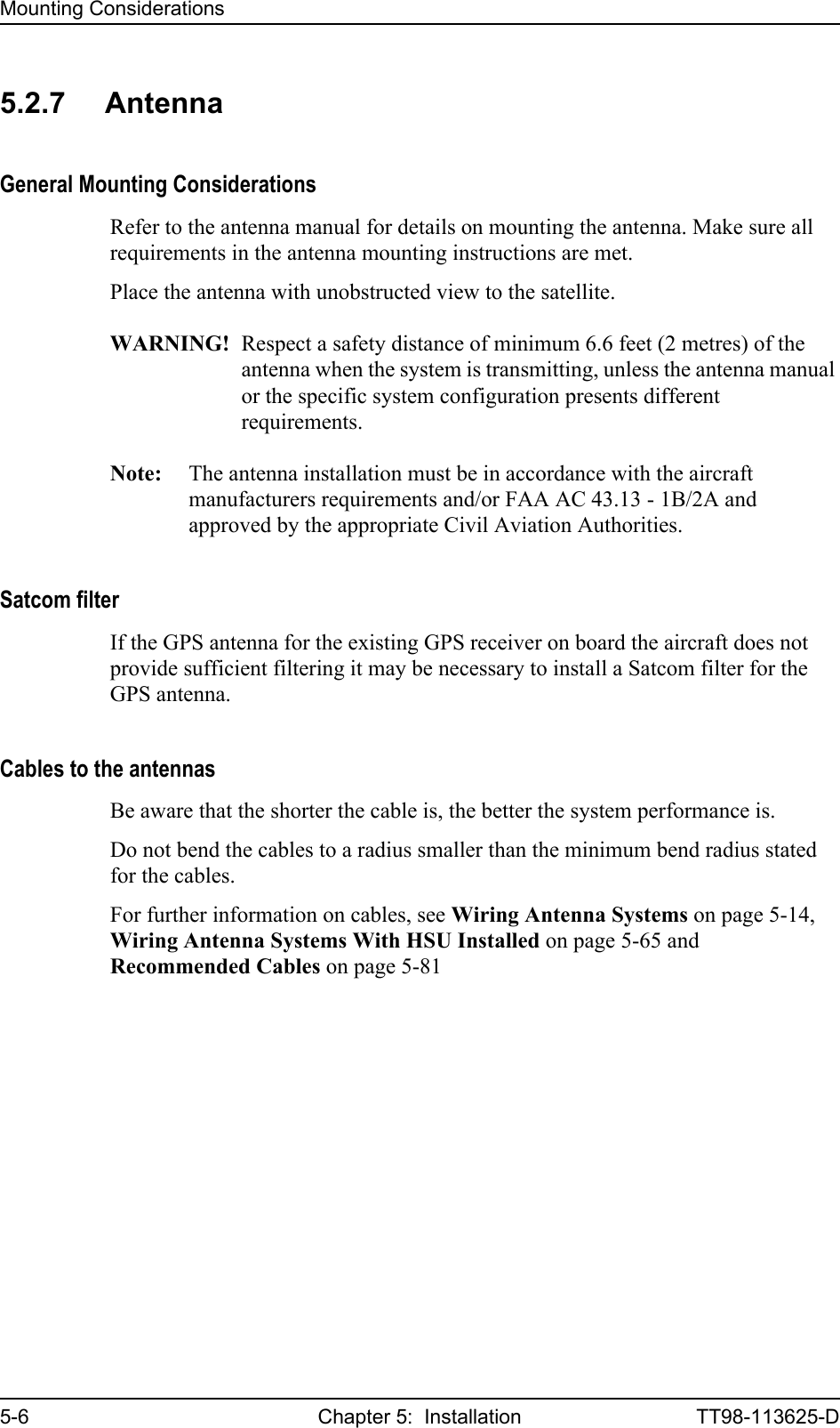
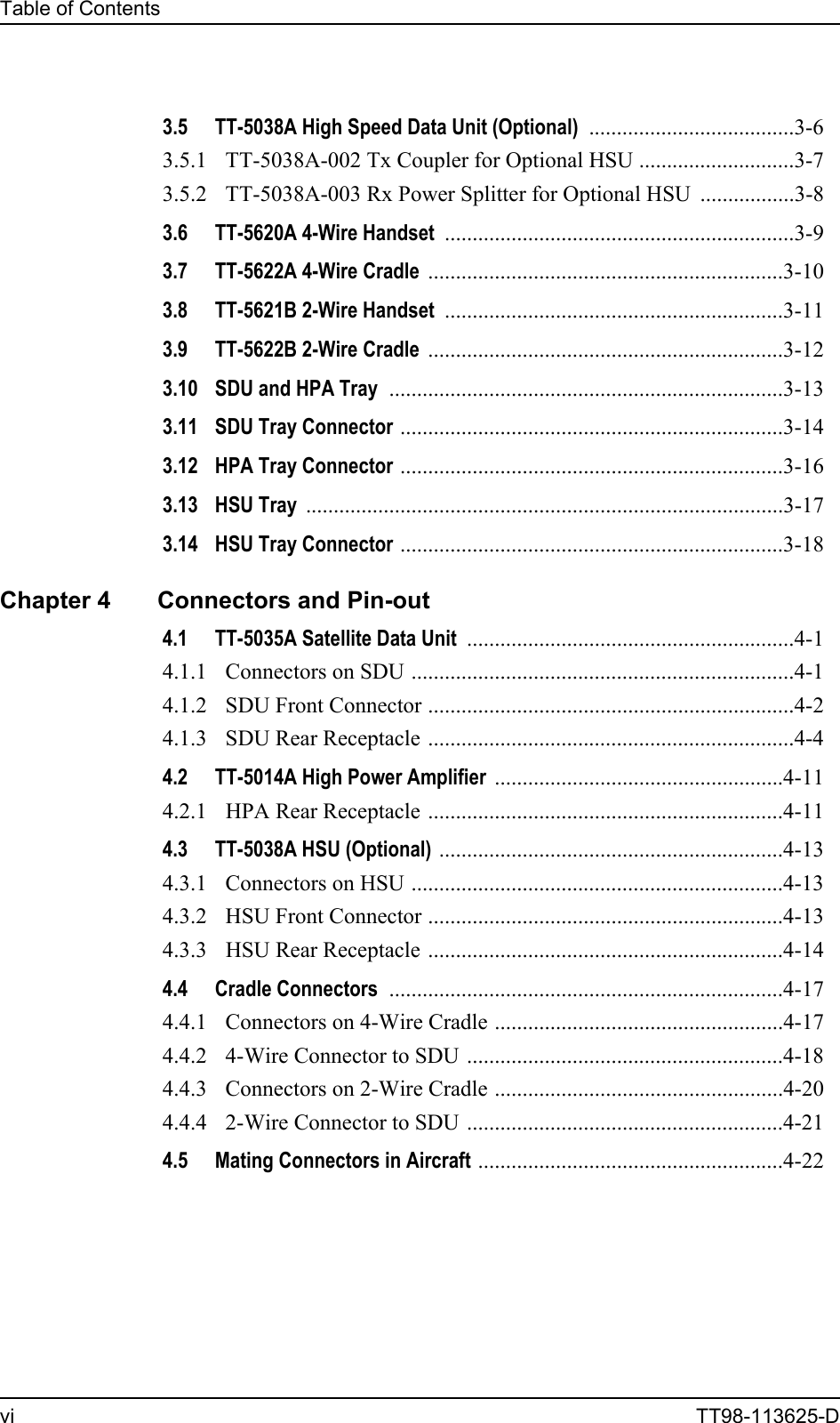
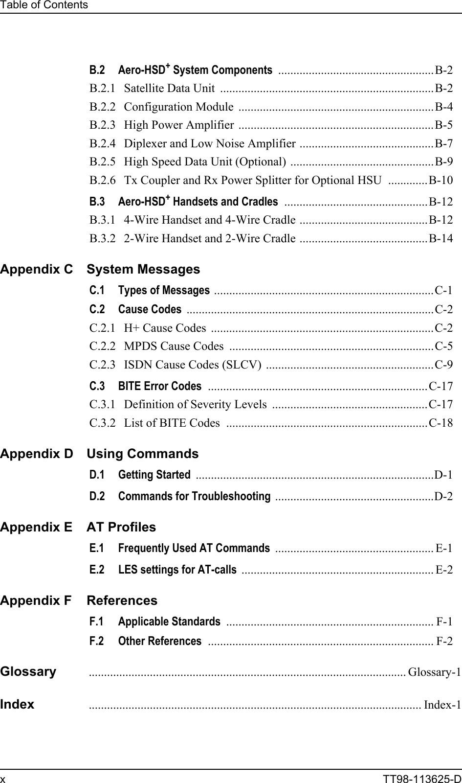
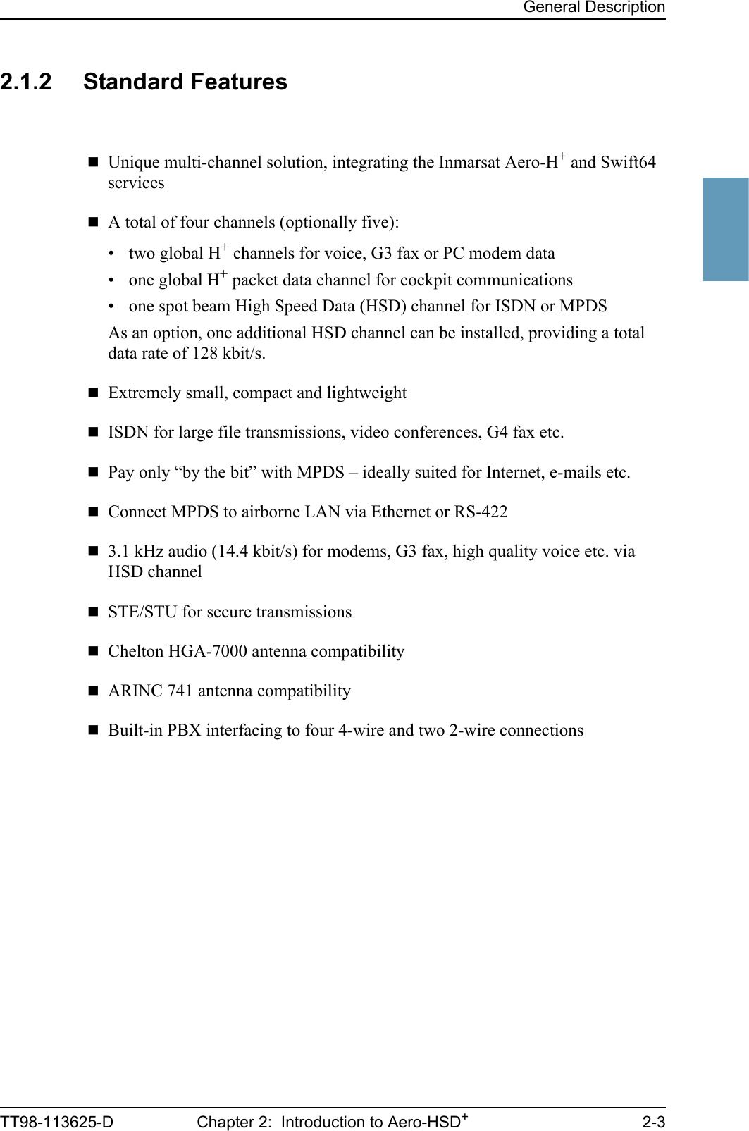
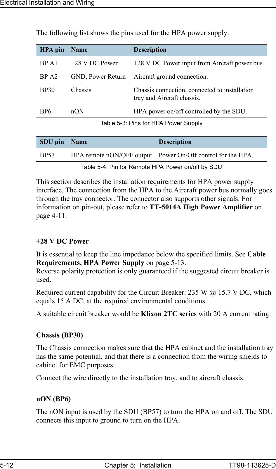
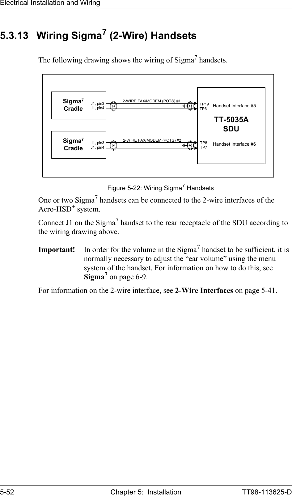
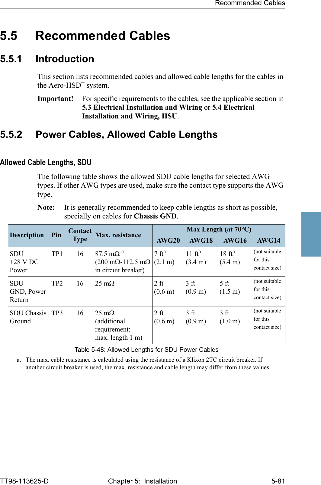
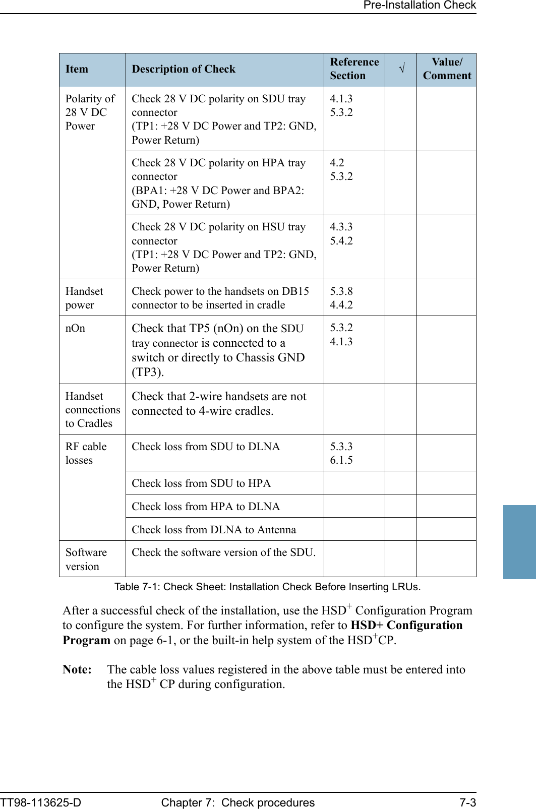
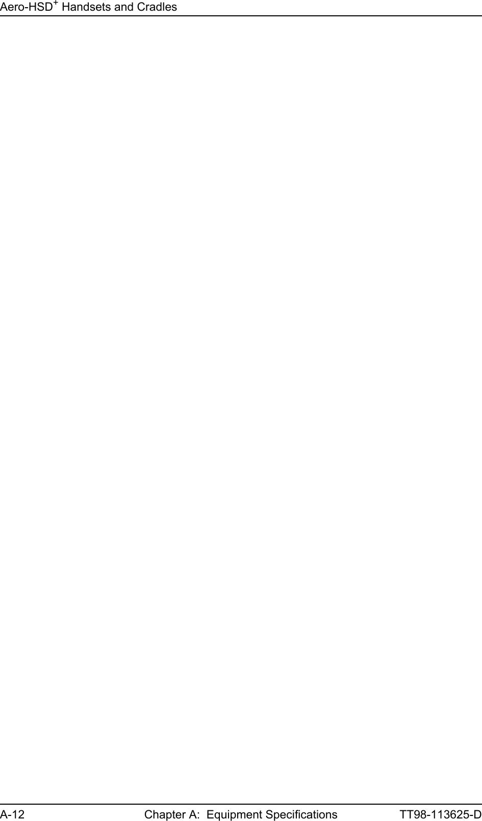
![Electrical Installation and Wiring5-8 Chapter 5: Installation TT98-113625-D5.3.2 Wiring Power SupplyImportant! Do not use the same 20 A circuit breaker for both the SDU and the HPA. Use separate circuit breakers as described in this section, and with the current rating stated here.Wiring of Satellite Data UnitThe Aircraft Power Bus provides the electric power required to operate the SDU, and a chassis connection to the aircraft chassis and the installation tray. The +28 V DC Power wire must include a circuit breaker capable of carrying the required current continuously under the required environmental conditions.The following drawing shows the wiring of the SDU power supply.Requirements to the wiring are stated in the notes on the drawing and in the section Cable Requirements, SDU Power Supply on page 5-10. Figure 5-3: Wiring SDU Power SupplyTT-5035ASDU[2] TP2 GND, Power ReturnTP528VDCAircraft Power Bus[1] Total resistance max. 200 mΩ incl. Circuit Breaker.[2] Total resistance max. 25 mΩ .[3] Directly to Aircraft chassis, max. 1 m cable length to prevent EMC problems and max. 25 mΩ resistance[4] Recommended circuit breaker: Klixon 2TC series, 4 A current rating[5] If SATCOM On/Off switch is required, TP5 is routed to an external switch to groundTP3TP1 +28 VDC PowerChassis Ground and Handset Power ReturnRemote ON/OFF (nON)[4]4A[5]20AWG[1][3]](https://usermanual.wiki/Thrane-and-Thrane-A-S/AERO-HSU/User-Guide-507698-Page-86.png)
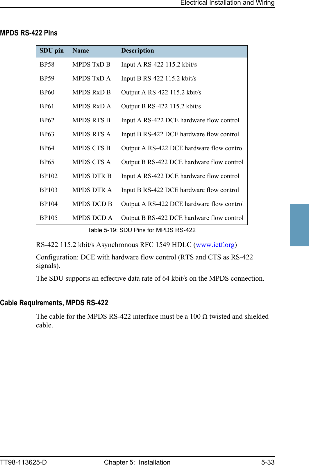
200 mΩ,incl. circuit breaker[2](GND, Power Return)25 mΩThe cable should be as short as possible.[3](Chassis Ground)25 mΩConnect directly to aircraft chassis.Table 5-2: Requirements to SDU Power Cables](https://usermanual.wiki/Thrane-and-Thrane-A-S/AERO-HSU/User-Guide-507698-Page-88.png)
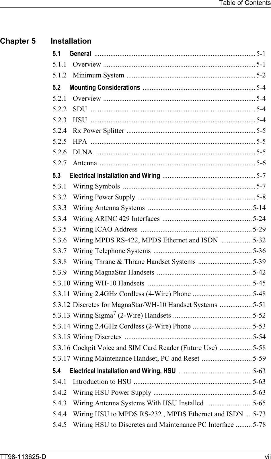
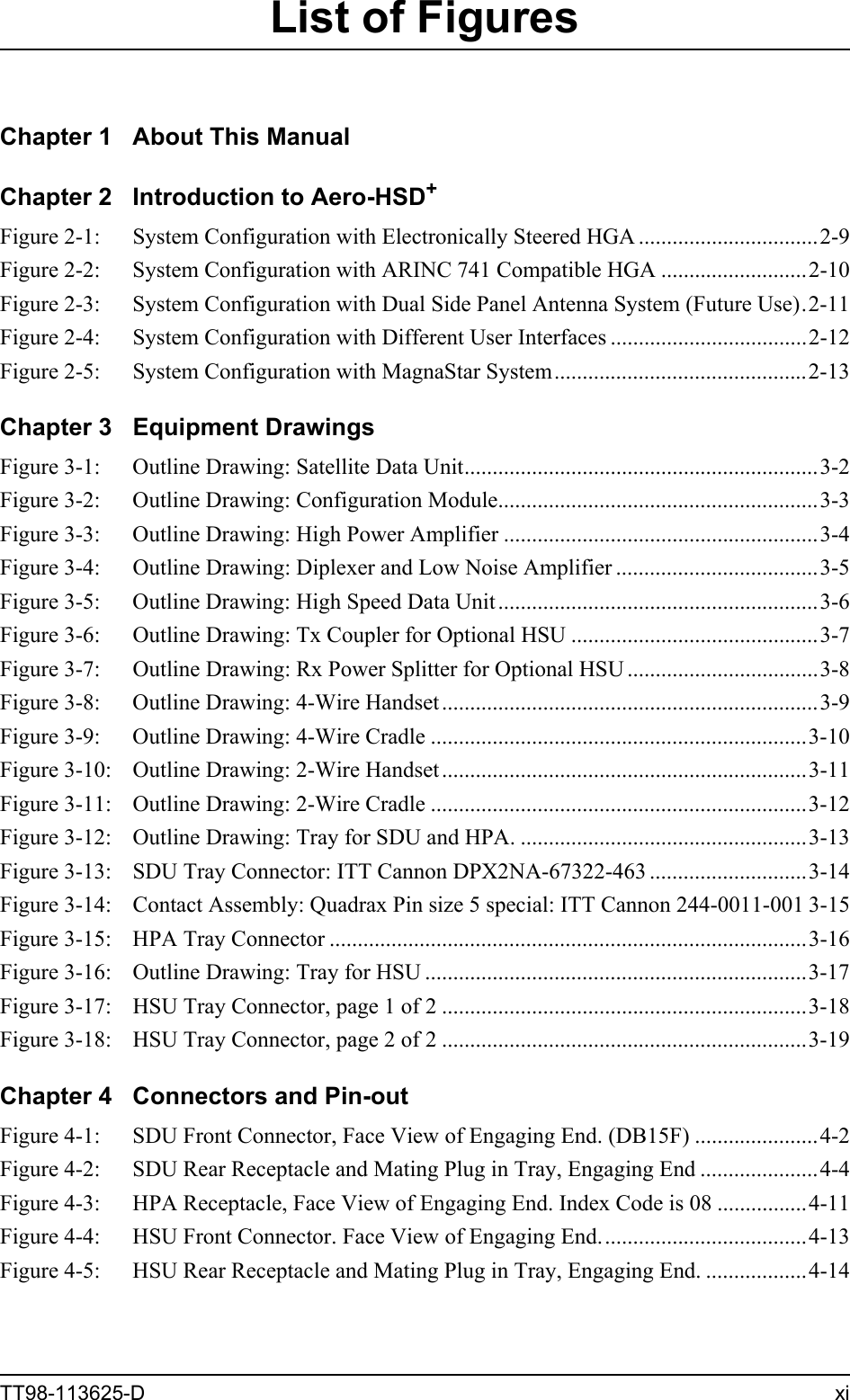
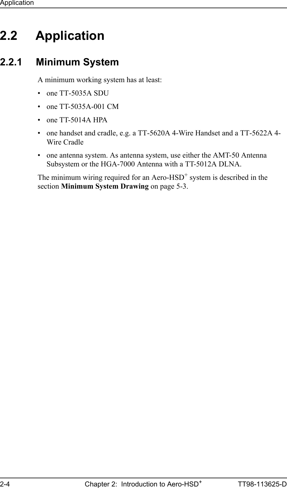
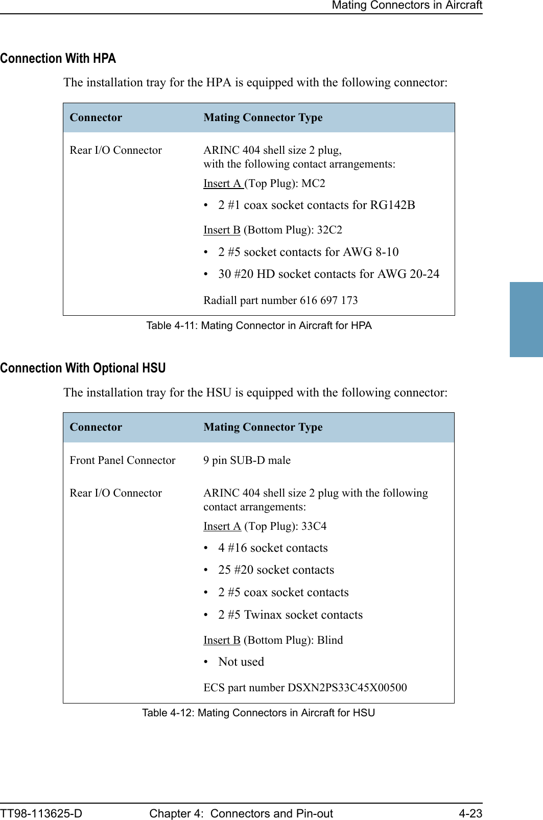
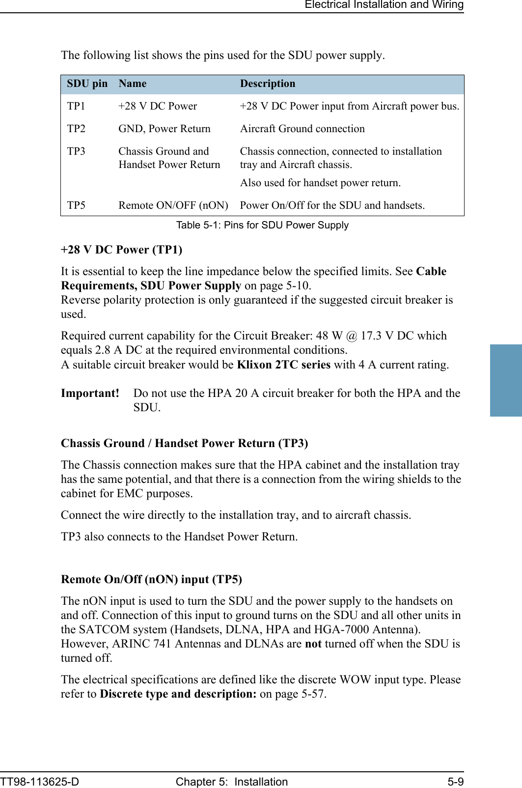
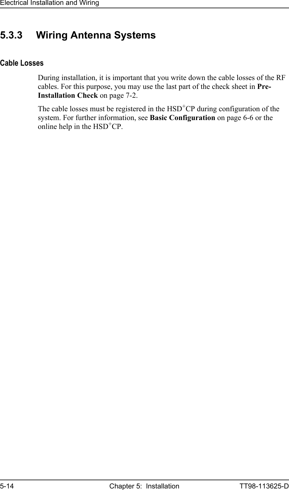
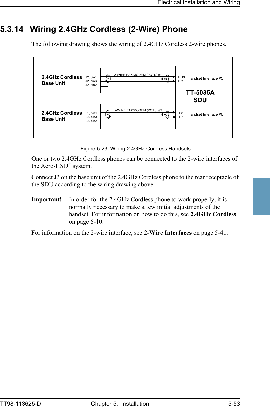
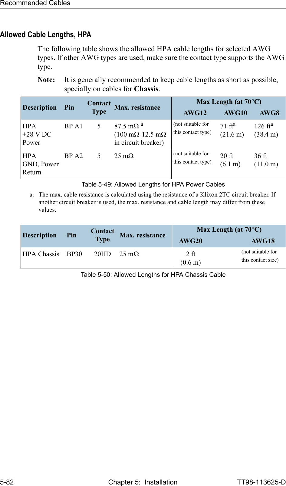
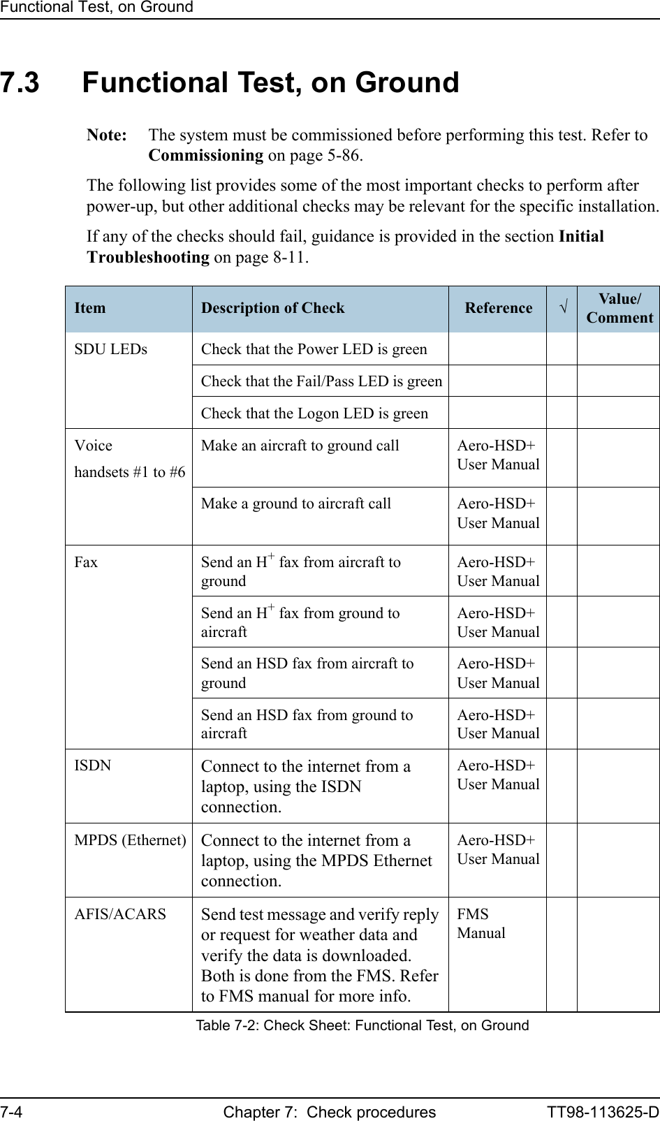
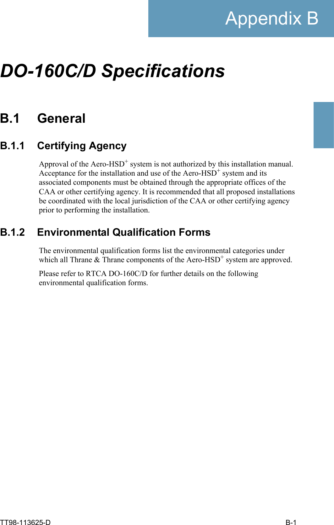
![Electrical Installation and WiringTT98-113625-D Chapter 5: Installation 5-115555Wiring of High Power AmplifierThe Aircraft power bus provides the electric power required to operate the HPA, and a chassis connection to the aircraft chassis and the installation tray. The +28 V DC Power wire must include a circuit breaker capable of carrying the required current continuously under the required environmental conditions.The following drawing shows the wiring of the HPA power supply.Requirements to the wiring are stated in the notes on the drawing and in the section Cable Requirements, HPA Power Supply on page 5-13.Figure 5-4: Wiring HPA Power SupplyTT-5014AHPA[2] BP A2 GND, Power Return28 V DCAircraft Power Bus[1] Total resistance max. 100 mΩ incl. Circuit Breaker.[2] Total resistance max. 25 mΩ.[3] Directly to Aircraft chassis, max. 0.6 m cable length (AWG 20) to prevent EMC problems and max. resistance 25 mΩ.[4] Recommended circuit breaker: Klixon 2TC series, 20 A current rating.[5] Must be shielded to prevent EMC problems.BP30 ChassisBP A1 +28 V DC PowerBP6 nON[4]20A[1][3]TT-5035ASDUBP57 [5]](https://usermanual.wiki/Thrane-and-Thrane-A-S/AERO-HSU/User-Guide-507698-Page-89.png)
100 mΩ,incl. circuit breaker[2](GND, Power Return)25 mΩ[3](Chassis)25 mΩConnect directly to aircraft chassis.[5](nON)- Must be shielded to avoid EMC problems.Table 5-5: Requirements to HPA Power Cables](https://usermanual.wiki/Thrane-and-Thrane-A-S/AERO-HSU/User-Guide-507698-Page-91.png)
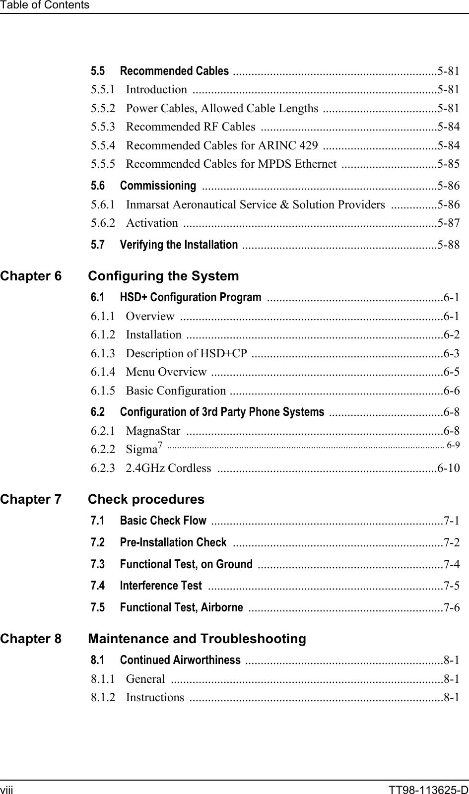
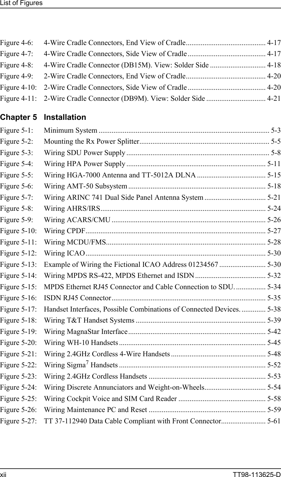
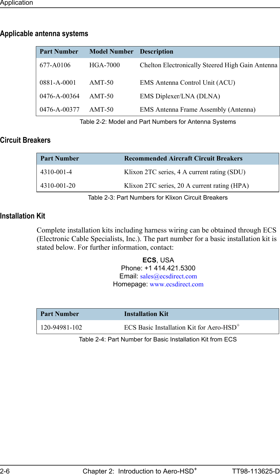
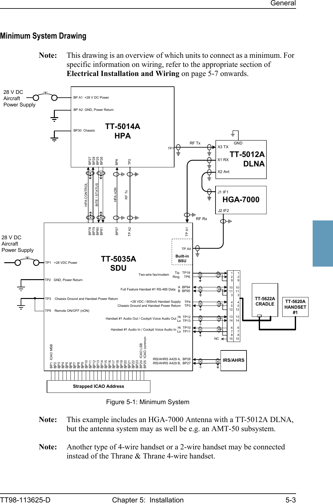
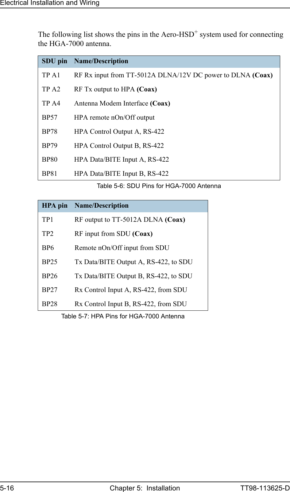
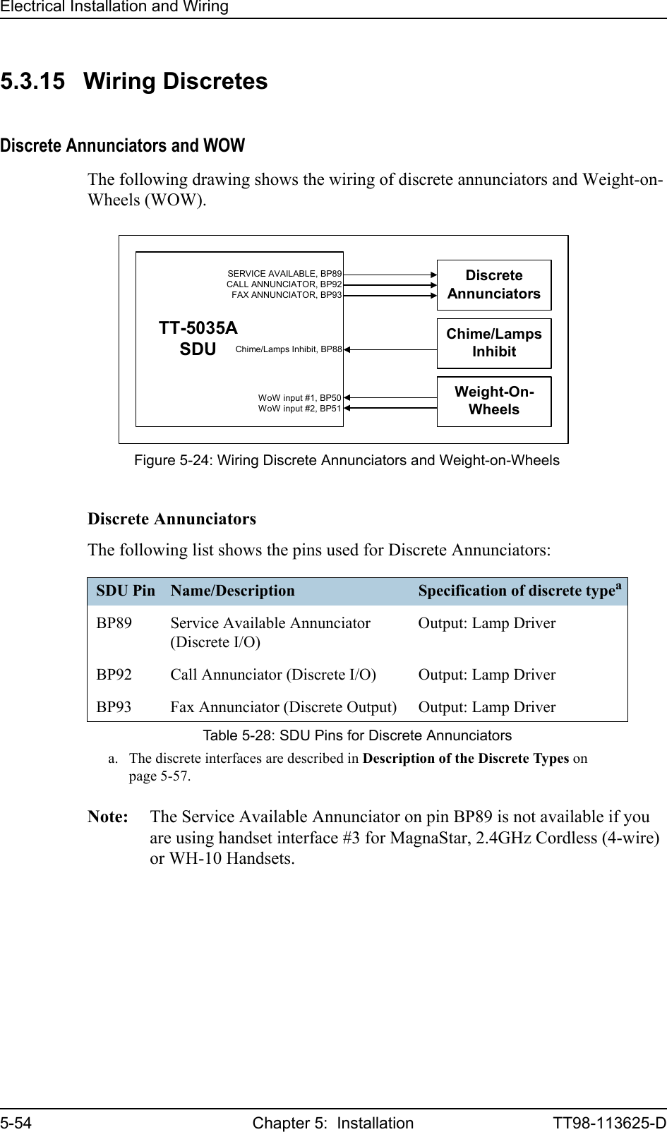
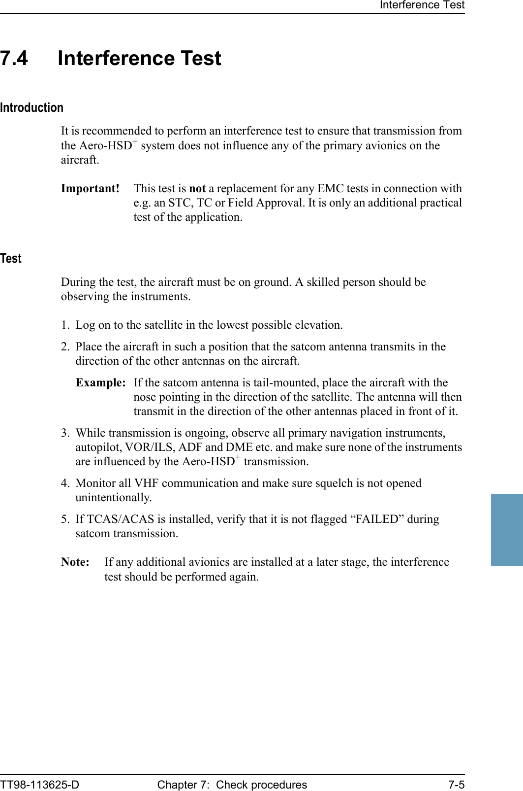
![Electrical Installation and WiringTT98-113625-D Chapter 5: Installation 5-155555Wiring of HGA-7000 AntennaThe following drawing shows the wiring for an Aero-HSD+ system using an HGA-7000 antenna.Note: For information on wiring an HGA-7000 Antenna when the TT-5038A HSU is installed, see HGA-7000 Antenna with HSU on page 5-65.Requirements to the cables are stated on the drawing and in the section Cable Requirements, HGA-7000 Antenna on page 5-17.Important! Remember to write down the cable losses. See Cable Losses on page 5-14.Figure 5-5: Wiring HGA-7000 Antenna and TT-5012A DLNATT-5035ASDUBP78BP79BP80BP81TP A2HPA nONBP57 BP6TP2BP27BP28BP25BP26TP A1TT-5014AHPA[1] Coax, loss from cable W6 max. 12 dB[2] Coax, loss from cable W5 max. 15 dB[3] Coax, total loss from cable W3 and cable W4 max. 1.8 dB[4] Coax, loss from cable W3 max. 0.3 dB[5] Coax, loss from cable W7 max. 17 dB[6] 16 AWG, max. 1 ft long, max. resistance 3 mΩHPA CONTROLDATA / BITETP1TT-5012ADLNAX3 TXX1 RXX2 AntHGA-7000TP A4[3], [4]W5W3W6J2 IF2J1 IF1Built-inBSUW7[2][5][1]GND[6]W4[3]](https://usermanual.wiki/Thrane-and-Thrane-A-S/AERO-HSU/User-Guide-507698-Page-93.png)
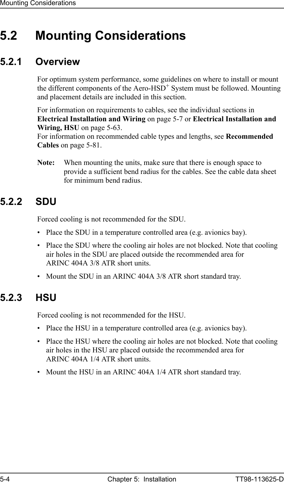
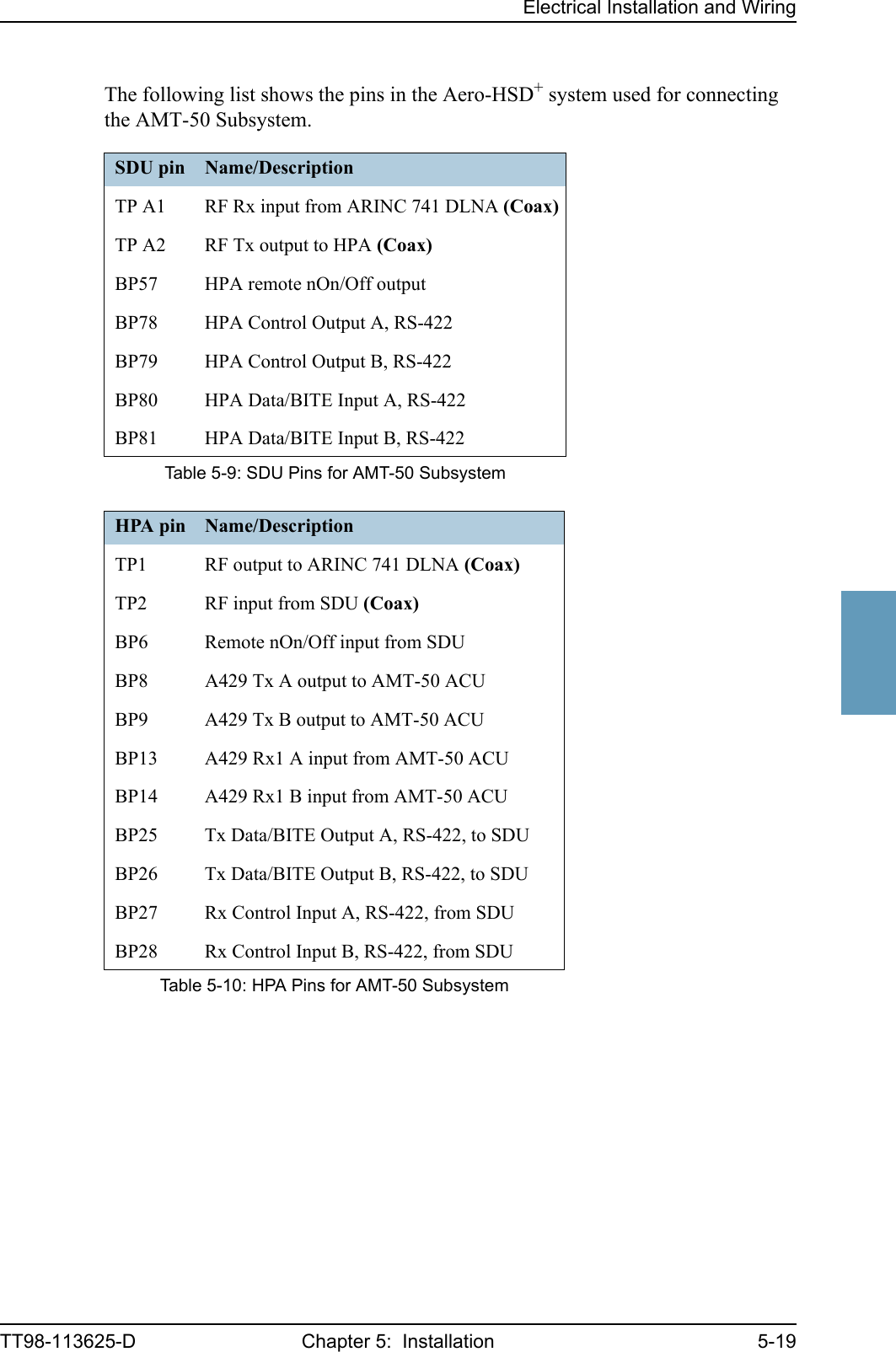
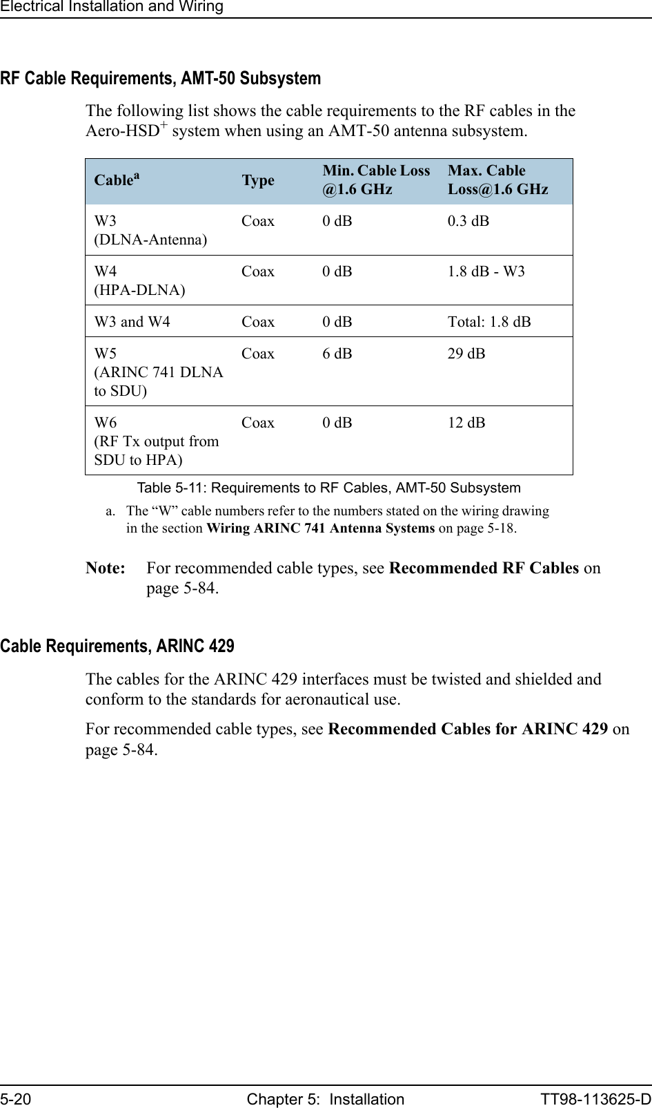
![Electrical Installation and Wiring5-18 Chapter 5: Installation TT98-113625-DWiring ARINC 741 Antenna SystemsThe following drawing shows the wiring for an Aero-HSD+ system using the AMT-50 antenna subsystem.Note: For information on wiring an AMT-50 subsystem when the TT-5038A HSU is installed, see AMT-50 Subsystem With HSU on page 5-69.Requirements to the cables are stated on the drawing and in the section RF Cable Requirements, AMT-50 Subsystem on page 5-20.Important! Remember to write down the cable losses. See Cable Losses on page 5-14.Figure 5-6: Wiring AMT-50 SubsystemTT-5035ASDUBP78BP79BP80BP81TP A2HPA nONBP57 BP6TP2BP27BP28BP25BP26TP A1TT-5014AHPAHPA CONTROLDATA / BITEBP8BP9BP13BP14AMT-50ACUA B G HTP1AMT-50DLNAJ3J2J1AMT-50 Subsystem[1] Coax, loss from cable W6 max. 12 dB[2] Coax, loss from cable W5 min. 6 dB and max. 29 dB[3] Coax, total loss from cable W3 and cable W4 max. 1.8 dB[4] Coax, loss from cable W3 max. 0.3 dBW5W6W4AMT-50Ant.W3[1][2][3][3] [4]A429 Tx (HS)A429 Rx (LS)](https://usermanual.wiki/Thrane-and-Thrane-A-S/AERO-HSU/User-Guide-507698-Page-96.png)
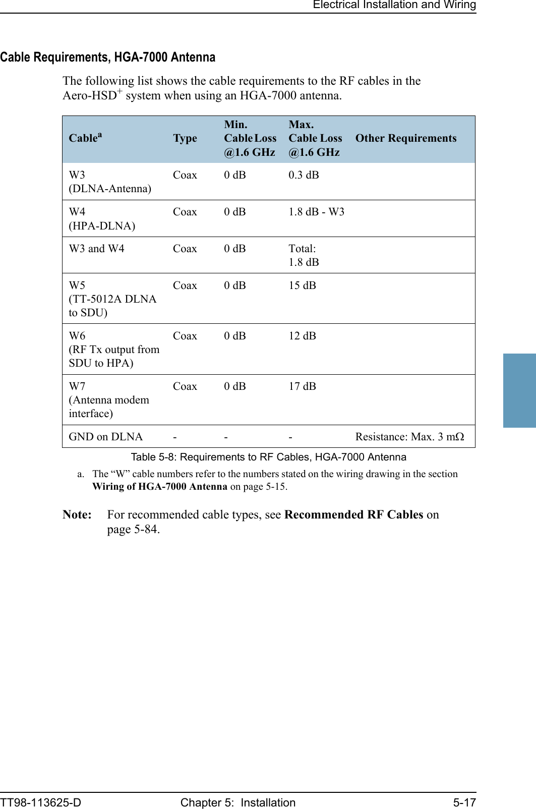
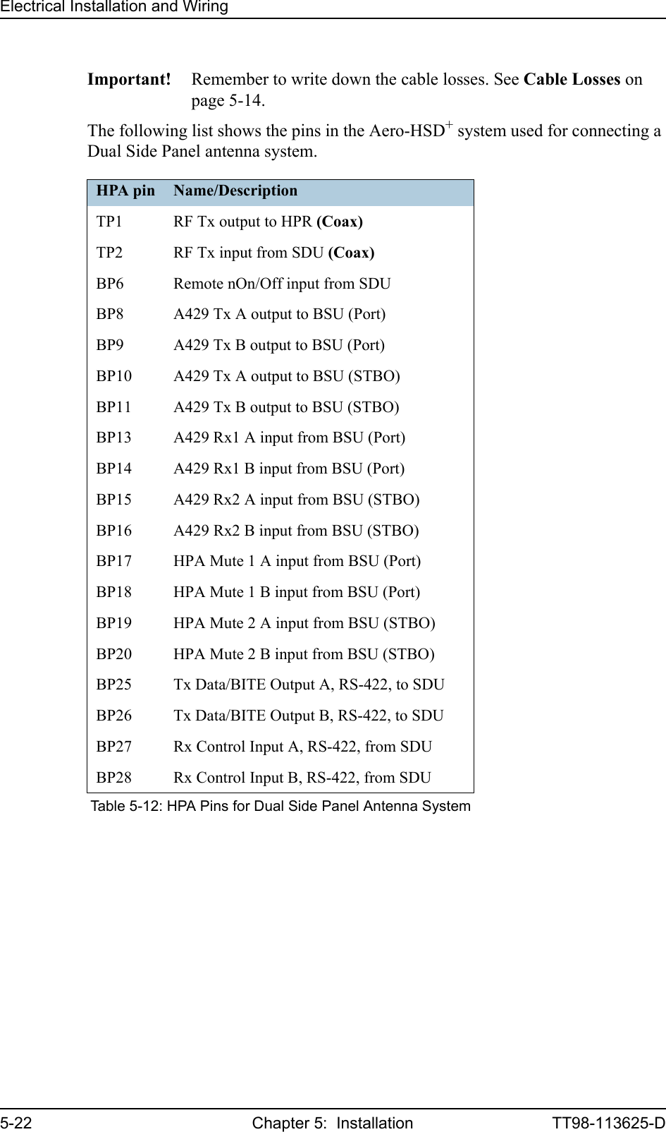
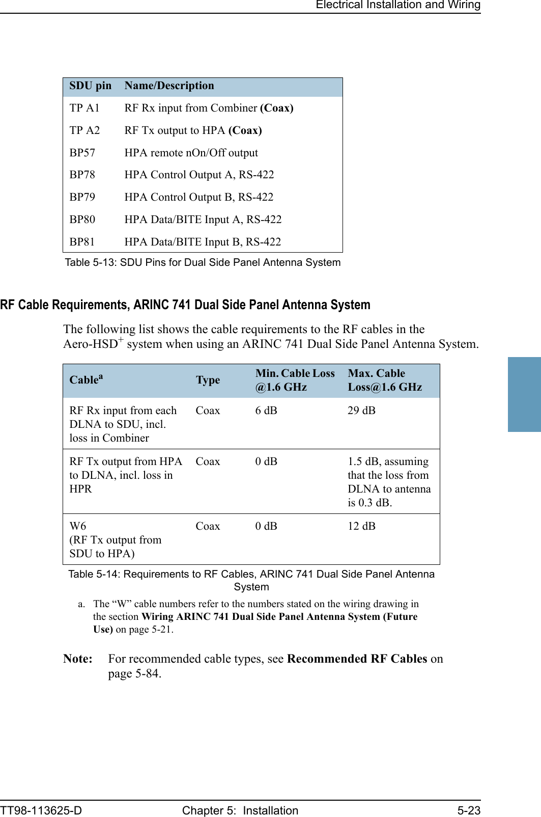
![Electrical Installation and WiringTT98-113625-D Chapter 5: Installation 5-215555Wiring ARINC 741 Dual Side Panel Antenna System (Future Use)The following drawing shows the wiring of an ARINC 741 dual side panel antenna system.Figure 5-7: Wiring ARINC 741 Dual Side Panel Antenna SystemTT-5014AHPAA429 Rx2 A, BP15A429 Rx2 B, BP16A429 Tx A, BP10A429 Tx B, BP11HPA Mute 2 A, BP19HPA Mute 2 B, BP20BSU(STBO)A429 Rx1 A, BP13A429 Rx1 B, BP14A429 Tx A, BP8A429 Tx B, BP9HPA Mute 1 A, BP17HPA Mute 1 B, BP18BSU(Port)WXTUGHWXTUGHDLNA(Port)AntHPRTx RxDLNA(STBO)AntTx RxRF Tx output, TP1HGA(Port)HGA(STBO)TT-5035ASDUTPA1Aero-HSD+ SystemBP27BP28BP25BP26HPA nONBP6 BP57BP78BP79BP80BP81HPA CONTROLData/BITETP A2TP2 RF TxRF RxCombinerARINC 741 Dual Side Panel Antenna System[1] Coax, loss from cable W6: max. 12 dB[2] Coax, total loss from each of the DLNAs to the SDU, including loss inthe Combiner: min. 6 dB and max. 29 dB[3] Coax, total loss from HPA to each of the DLNAs, including loss in theHPR: max. 1.5 dB, assuming that the total loss from DLNA to antenna is0.3 dB.W6[1][2][2][2][3] [3][3]](https://usermanual.wiki/Thrane-and-Thrane-A-S/AERO-HSU/User-Guide-507698-Page-99.png)
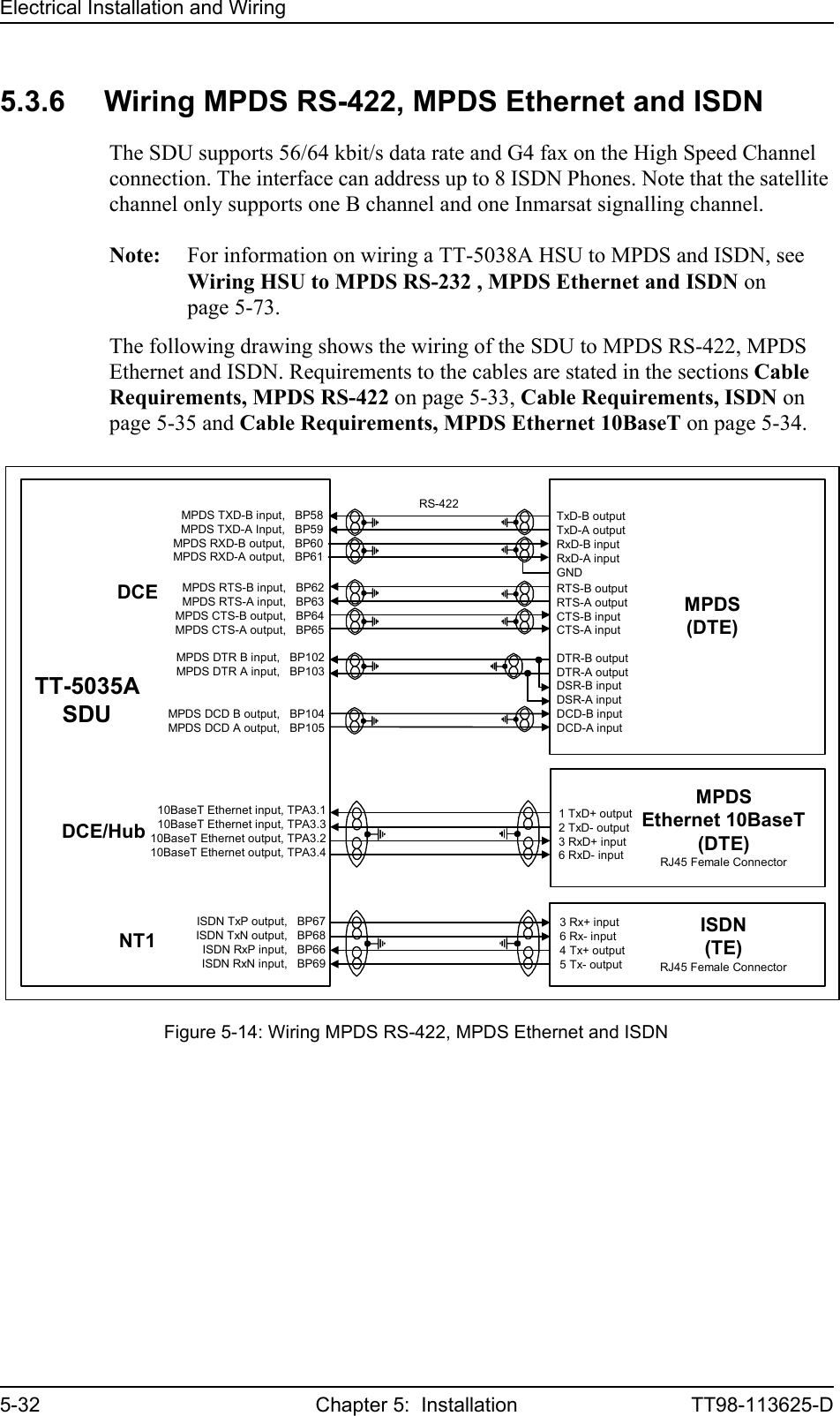
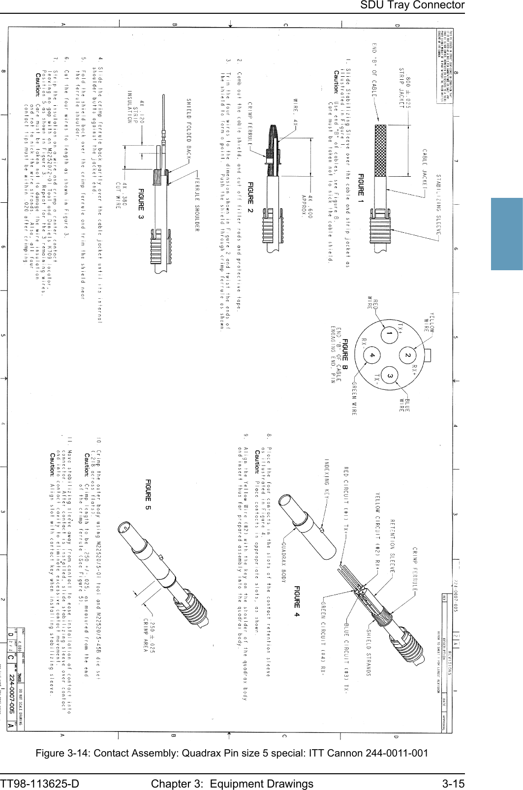
![Electrical Installation and Wiring5-34 Chapter 5: Installation TT98-113625-DMPDS Ethernet 10BaseT PinsThe SDU Rear Connector Top Plug (TP) has a Quadrax connector insert in TP A3, used for MPDS over Ethernet.Important! Make sure the coding pin is inserted properly when you plug in the Quadrax connector. It is possible to accidentally misplace the coding pin, which could damage the connector or the SDU.Refer to Figure 3-14: Contact Assembly: Quadrax Pin size 5 special: ITT Cannon 244-0011-001 for information on assembly of the Quadrax connector.The 10 Mbit/s Ethernet interface physical layer conforms to [1] (IEEE standard 802.3, Chapter 14: “Twisted Pair medium attachment unit”), except for the connector type. To be compliant with [1], an RJ45 female connector must be used for the user interface. The connector pin assignment must be according to [1] and [2] as shown in Figure 5-15: MPDS Ethernet RJ45 Connector and Cable Connection to SDU. The SDU is defined as a DCE or a Hub i.e. TxD is input and RxD is output. Cable Requirements, MPDS Ethernet 10BaseTThe cable for the MPDS Ethernet 10BaseT interface must be a 100 Ω 4-wire twisted and shielded cable.Recommended cable types are listed in Cables for MPDS Ethernet on SDU (Quadrax Connector) on page 5-85.SDU pin Name Description RJ45 PIN (F) NameTP A3.1 Tx+ Input 1 TxD+TP A3.2 Rx+ Output 3 RxD+TP A3.3 Tx- Input 2 TxD-TP A3.4 Rx- Output 6 RxD-Table 5-20: SDU Pins for MPDS 10BaseT Ethernet Figure 5-15: MPDS Ethernet RJ45 Connector and Cable Connection to SDU.RJ45female12345678TxD+ TX+ inputn.c.TxD- TX- inputRxD+ RX+ outputn.c.RxD- RX- outputn.c.n.c.SDU pin TP A3to DTE100Ω Quadrax twistedand shielded pairsSDU (DCE/Hub)123456783241ShieldView: Cable insert](https://usermanual.wiki/Thrane-and-Thrane-A-S/AERO-HSU/User-Guide-507698-Page-112.png)
![Electrical Installation and WiringTT98-113625-D Chapter 5: Installation 5-355555ISDN PinsThe Euro ISDN S-bus interface on the SDU is configured as the network side of the NT1 interface i.e. Rx is an input and Tx is an output. Please note that this configuration of input and output differs from the configuration of the 10BaseT Ethernet, RS-422 MPDS and RS-232 PC interface input/output.An RJ-45 Female Connector must be connected to the four wire ISDN lines from the SDU in order to be compliant with [2] (ISO8877 ISO/IEC 8877) and the ISDN connector specification defined by [5] (ITU-T Recommendation I.420). The SDU includes an internal 100 Ω termination resistor to support cable lengths longer than 3 meters.The Euro ISDN S-bus interface can power supply 4 ISDN phones but supports 8 phones (where 4 of them must have their own power supply). At power hold-up, only power for one phone is available i.e. if more than one phone is connected, the SDU may reset if an incoming call is received, or if more than one phone is off-hook, during a power hold-up session. Cable Requirements, ISDNThe cable for the ISDN interface must be a 100 Ω 4-wire shielded cable. The conductors must be twisted in pairs.SDU pin Name Description RJ45 PIN (F) NameBP67 ISDN TxP Output 3 Rx+BP68 ISDN TxN Output 6 Rx-BP66 ISDN RxP Input 4 Tx+BP69 ISDN RxN Input 5 Tx-Table 5-21: SDU Pins for ISDNFigure 5-16: ISDN RJ45 Connector12345678ISDN Rx+ InputISDN Tx+ OutputISDN Tx- OutputISDN Rx- Inputn.c.n.c.n.c.n.c.RJ45 (Female Connector)RJ45female12345678](https://usermanual.wiki/Thrane-and-Thrane-A-S/AERO-HSU/User-Guide-507698-Page-113.png)
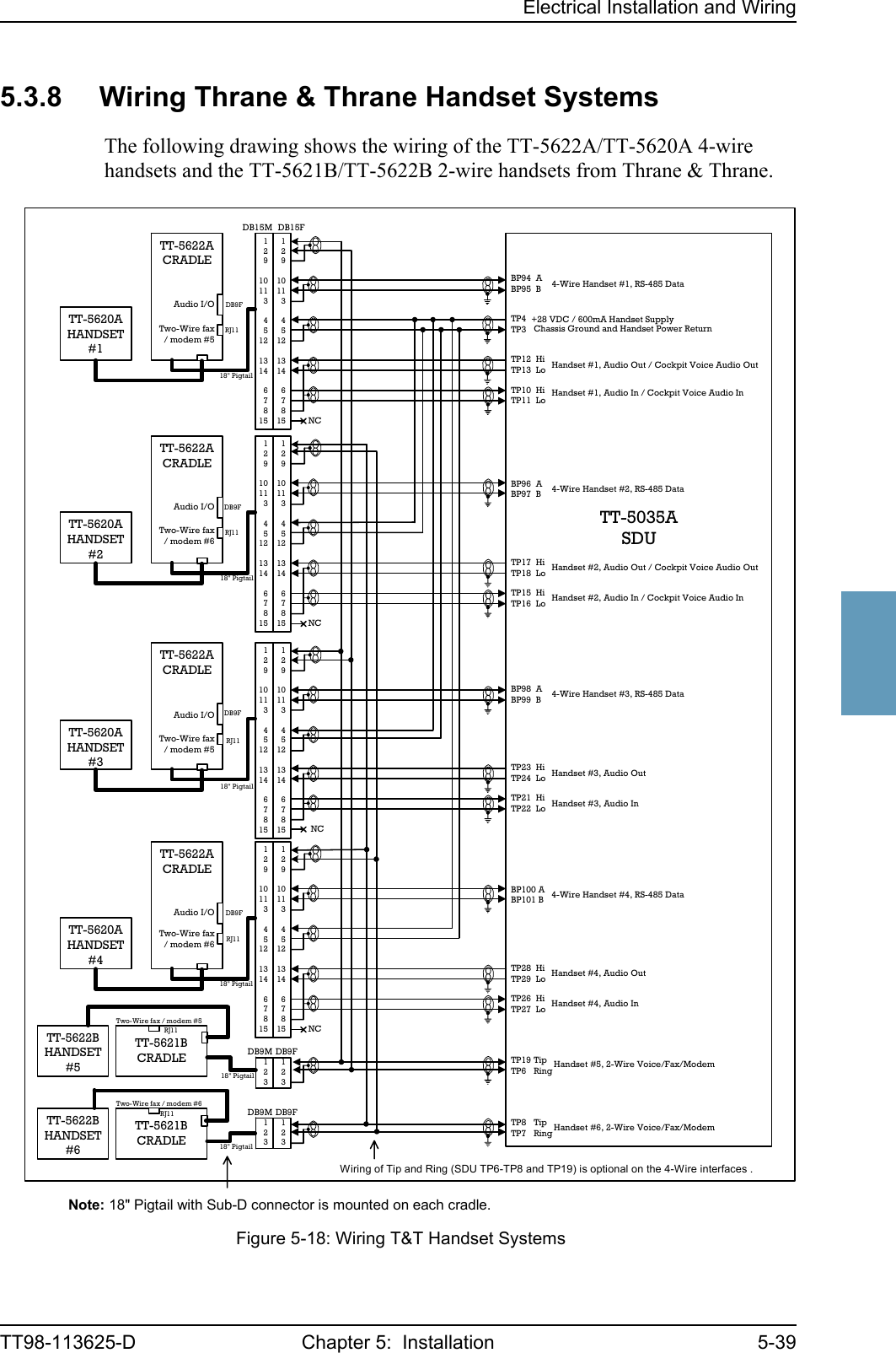
![Electrical Installation and Wiring5-38 Chapter 5: Installation TT98-113625-DConfiguration of Handset InterfacesThe following drawing shows the possible combinations of devices connected to the handset interfaces.Figure 5-17: Handset Interfaces, Possible Combinations of Connected Devices.[1]: Maximum two MagnaStar AIUs may be installed. The preferredinstallation of AIU #1 is to the four-wire Handset #1 interface, but AIU #1may alternatively be connected to the four-wire Handset #3 interfaceinstead.[2]: A Maximum of 8 ISDN units may be installed, and a maximum of twoISDN units may be active (off hook) at the time. ISDN phones may berouted to any four-wire, two-wire or RF channel, but ISDN modem data isonly routed to the High Speed RF channel.TT-5035A SDU,Private Branch Exchange (PBX)4-wire audioControl signalsTT-5020A / TT-5022A Handset System orMagnastar[1] AIU #1 or2.4 GHz Wireless Phone / WH-10 orCockpit Voice AMS #1 (future application)Four-wire Handset interface #14-wire audioControl signalsTT-5020A / TT-5022A Handset System orMagnastar[1] AIU #2 or2.4 GHz Wireless Phone / WH-10 orCockpit Voice AMS #2 (future application)Four-wire Handset interface #24-wire audioControl signalsTT-5020A / TT-5022A Handset System orAlternative: Magnastar[1] AIU #1 or2.4 GHz Wireless Phone / WH-10Four-wire Handset interface #34-wire audioControl signalsTT-5020A / TT-5022A Handset SystemFour-wire Handset interface #42-wire POTSTT-5021B / TT-5022B cradle/handset or2.4 GHz Wireless Phone / POTS orSigma7 Phone orFAX or ModemTwo-wire Handset interface #52-wire POTSTT-5021B / TT-5022B cradle/handset or2.4 GHz Wireless Phone / POTS orSigma7 Phone orFAX or ModemTwo-wire Handset interface #6ISDNISDN Phones / ISDN Modem [2]ISDN interface](https://usermanual.wiki/Thrane-and-Thrane-A-S/AERO-HSU/User-Guide-507698-Page-116.png)
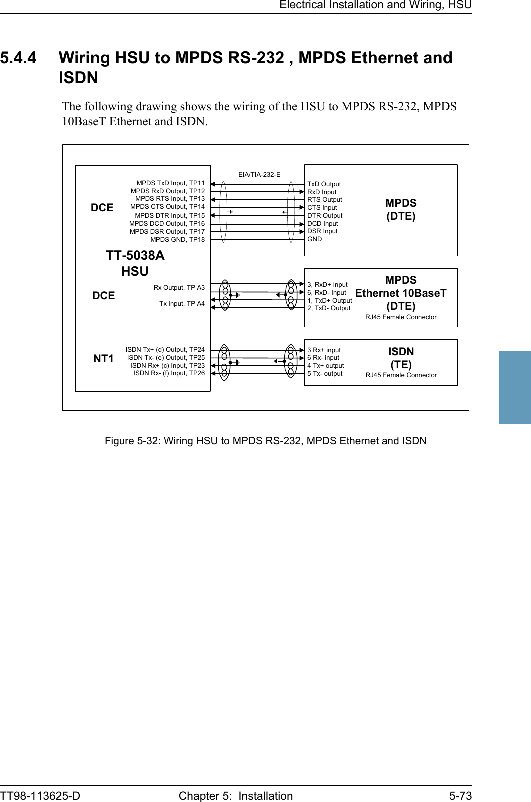
![Electrical Installation and Wiring, HSUTT98-113625-D Chapter 5: Installation 5-6355555.4 Electrical Installation and Wiring, HSU5.4.1 Introduction to HSUAs an option, a High Speed data Unit (HSU) containing one additional HSD channel is available for the Aero-HSD+ system, providing a total data rate of 128 kbit/s. The following pages provide information on wiring of the units in the Aero-HSD+ system with an additional High Speed data Unit (HSU) installed. 5.4.2 Wiring HSU Power SupplyThe SDU to Aircraft power bus interfaces supply the electric power required to operate the HSU, and for EMC purposes a chassis connection to the aircraft chassis and the installation tray. The +28 V DC Power wire must include a circuit breaker capable of carrying the required current continuously under the required environmental conditions.The following drawing shows the wiring of the HSU to the Aircraft Power Bus.Figure 5-29: Wiring HSU PowerTT-5038AHSU[2] TP2 GND, Power Return28 V DCAircraft Power Bus[1] Total resistance max. 725 mΩ incl. Circuit Breaker.[2] Total resistance max. 25 mΩ.[3] Directly to Aircraft chassis, max. 1 m cable length to prevent EMC problems andmax. 25 mΩ resistance.[4] Recommended circuit breaker: Klixon 2TC series, 4 A current rating.TP3TP1 +28 V DC PowerChassis Ground[4]4A[1][3]](https://usermanual.wiki/Thrane-and-Thrane-A-S/AERO-HSU/User-Guide-507698-Page-141.png)
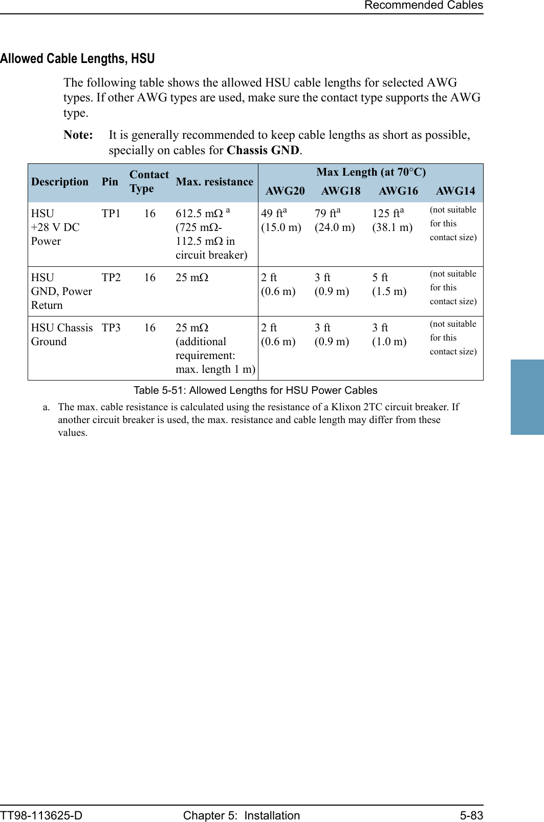
725 mΩ,incl. circuit breaker[2](GND, Power Return)25 mΩThe cable should be as short as possible.[3](Chassis Ground)25 mΩConnect directly to aircraft chassis.Table 5-34: Requirements to HSU Power Cables](https://usermanual.wiki/Thrane-and-Thrane-A-S/AERO-HSU/User-Guide-507698-Page-142.png)
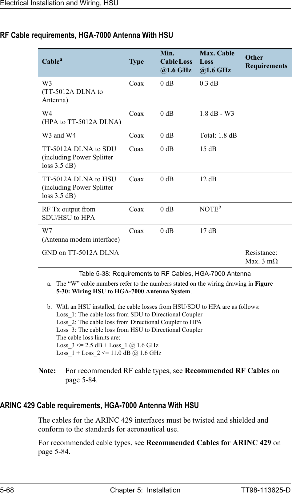
![Electrical Installation and Wiring, HSUTT98-113625-D Chapter 5: Installation 5-6555555.4.3 Wiring Antenna Systems With HSU InstalledHGA-7000 Antenna with HSUFigure 5-30: Wiring HSU to HGA-7000 Antenna SystemHSU TX CouplerTT-5038A-002TT-5035ASDUHGA-7000TP A4 J2 IF2J1 IF1Built-inBSUW7 [6]TT-5012ADLNAX3 TXX1 RX X2 AntGND[7]PowerSplitter3.5 dB @1.6GHzHSUSDUDLNAHSU RX Power SplitterTT-5038A-003TT-5038AHSUARINC 429BP56BP32BP33BP34BP35TP8TP19TP20TP21TP22ARINC 429HSU disableTP A1TP A2SDU HPAHSUTP2TT-5014AHPATP1BP78BP79BP80BP81HPA nONBP57 BP6BP27BP28BP25BP26HPA CONTROLBITE / STATUSTP A1TP A2W3[4], [5]RF RX COAX [1], [2]RF RX COAX [2]W4 [4]RF TX COAXLoss_3 [3]RF TX COAXLoss_1 [3]RF TX COAXLoss_2 [3]RF RX COAX [1][1] The total cable loss - including the power splitter loss (3.5 dB) - between the DLNA and the SDU must be: 0 to 15 dB @ 1.6 GHz[2] The total cable loss - including the power splitter loss (3.5 dB) - between the DLNA and the HSU must be: 0 to 12 dB @ 1.6 GHz[3] The cable losses from HSU/SDU to HPA are:Loss_1: The cable loss from SDU to Tx CouplerLoss_2: The cable loss from Tx Coupler to HPALoss_3: The cable loss from HSU to Tx CouplerThe cable loss limits are:Loss_3 <= 2.5 dB + Loss_1 @ 1.6 GHzLoss_1 + Loss_2 <= 11.0 dB @ 1.6 GHz[4] Coax, total loss from cable W3 and cable W4 max. 1.8 dB @ 1.6 GHz[5] Coax, loss from cable W3 max. 0.3 dB @ 1.6 GHz[6] Coax, loss from cable W7 max. 17 dB @ 1.6 GHz[7] 16 AWG, max. 1 ft long, max. resistance 3 mΩ](https://usermanual.wiki/Thrane-and-Thrane-A-S/AERO-HSU/User-Guide-507698-Page-143.png)
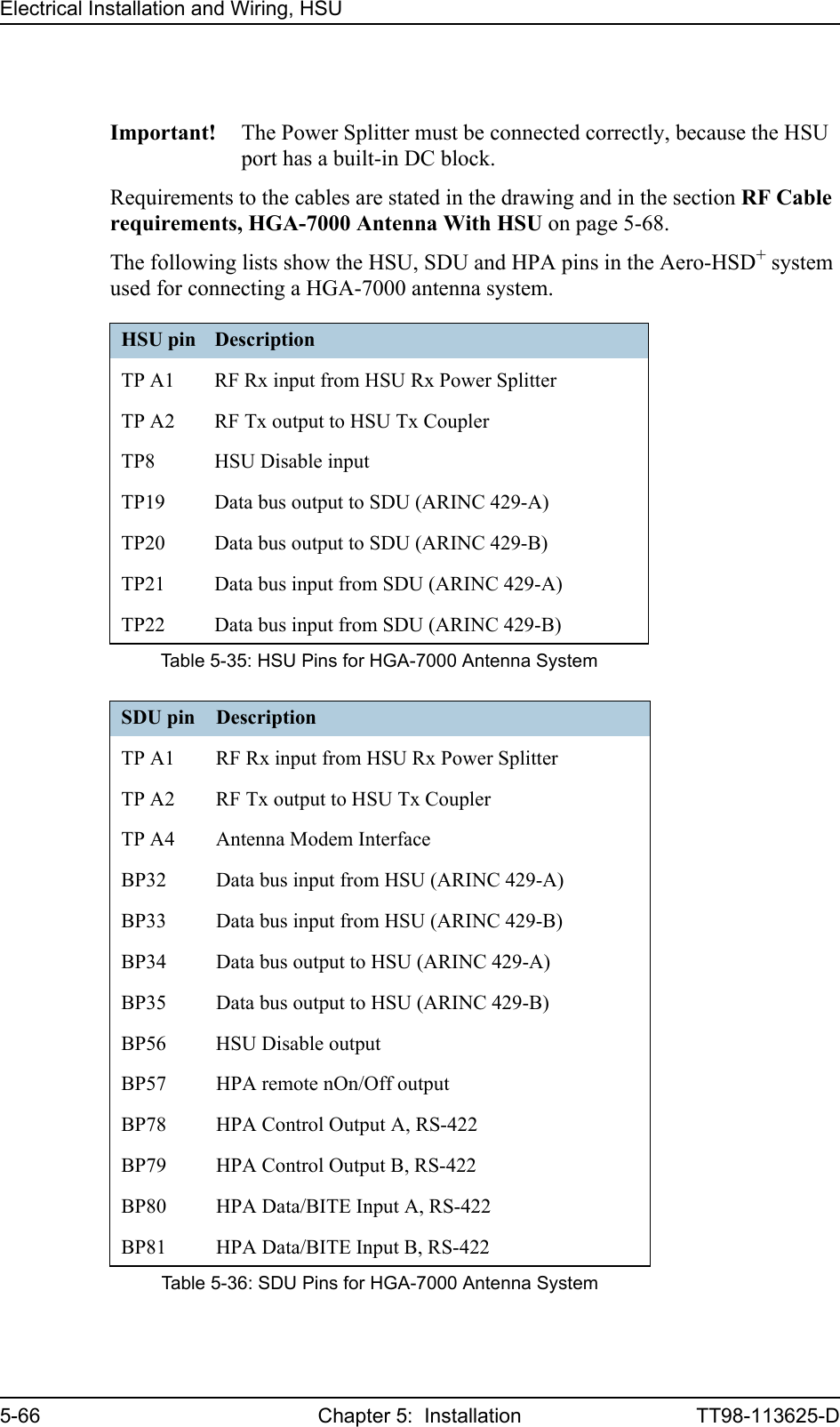
![Electrical Installation and Wiring, HSUTT98-113625-D Chapter 5: Installation 5-675555ARINC 429 Interface (TP19-TP22)The ARINC 429 interface is used by the SDU to control the HSU. The HSU operates as a slave to the SDU. The Interface is a 100 kbit/s High Speed ARINC 429 duplex data bus to/from the SDU. For electrical specifications refer to the ARINC 429 standard [6]. HSU Disable (TP8)The SDU uses the HSU Disable input to reset and inhibit the transmitter output signal from the HSU. The electrical specification is defined as for the discrete Weight-On-Wheels input type.HPA pin DescriptionTP1 RF Tx output to DLNATP2 RF Tx input from HSU Tx CouplerBP6 Remote nOn/Off input from SDUBP25 Tx Data/BITE Output A, RS-422, to SDUBP26 Tx Data/BITE Output B, RS-422, to SDUBP27 Rx Control Input A, RS-422, from SDUBP28 Rx Control Input B, RS-422, from SDUTable 5-37: HPA Pins for HGA-7000 Antenna System](https://usermanual.wiki/Thrane-and-Thrane-A-S/AERO-HSU/User-Guide-507698-Page-145.png)
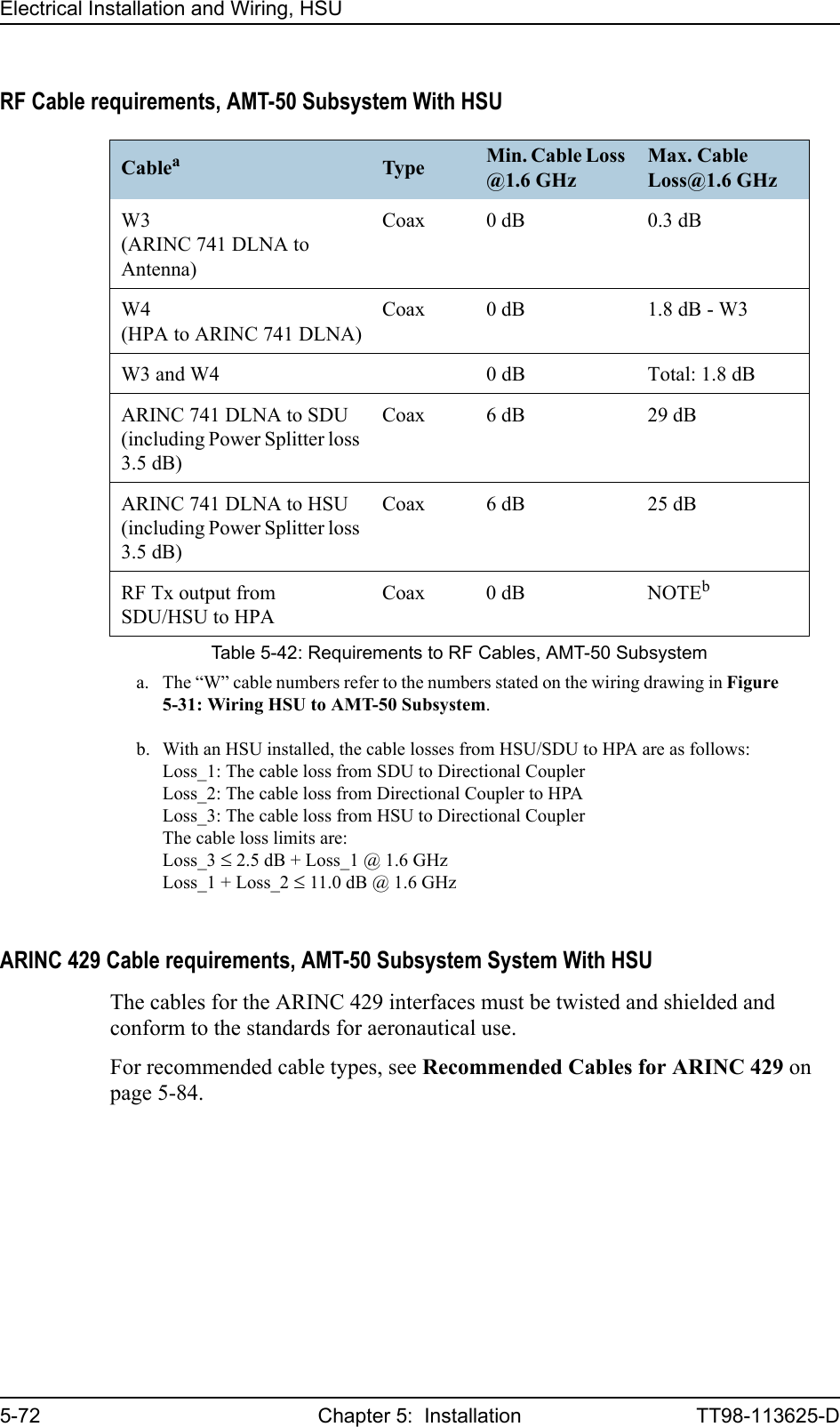
![Electrical Installation and Wiring, HSUTT98-113625-D Chapter 5: Installation 5-695555AMT-50 Subsystem With HSUFigure 5-31: Wiring HSU to AMT-50 SubsystemHSU TX CouplerTT-5038A-002TT-5035ASDUAMT-50AntennaAMT-50DLNAPowerSplitter3.5 dB @1.6GHzHSUSDUDLNAHSU RX Power SplitterTT-5038A-003TT-5038AHSUARINC 429BP56BP32BP33BP34BP35TP8TP19TP20TP21TP22ARINC 429HSU disableTP A1TP A2SDU HPAHSUTP2TT-5014AHPATP1BP78BP79BP80BP81HPA nONBP57 BP6BP27BP28BP25BP26HPA CONTROLData/BITETP A1TP A2RF RX COAX [1], [2]RF RX COAX [2]W4[4]RF TX COAXLoss_3 [3]RF TX COAXLoss_1 [3]RF TX COAXLoss_2 [3]RF RX COAX [1][1] The total cable loss - including the power splitter loss (3.5 dB) - between the DLNA and the SDU must be: 6 to 29 dB @ 1.6 GHz[2] The total cable loss - including the power splitter loss (3.5 dB) - between the DLNA and the HSU must be: 6 to 25 dB @ 1.6 GHz[3] The cable losses from HSU/SDU to HPA are:Loss_1: The cable loss from SDU to Tx CouplerLoss_2: The cable loss from Tx Coupler to HPALoss_3: The cable loss from HSU to Tx CouplerThe cable loss limits are:Loss_3 <= 2.5 dB + Loss_1 @ 1.6 GHzLoss_1 + Loss_2 <= 11.0 dB @ 1.6 GHz[4] Coax, total loss from cable W3 and cable W4 max. 1.8 dB @ 1.6 GHz[5] Coax, loss from cable W3 max. 0.3 dB @ 1.6 GHzAMT-50ACUA B H GW3[4] [5)BP8BP9BP13BP14A429 Tx (HS)A429 Rx (LS)J3J1J2AMT-50 Subsystem](https://usermanual.wiki/Thrane-and-Thrane-A-S/AERO-HSU/User-Guide-507698-Page-147.png)
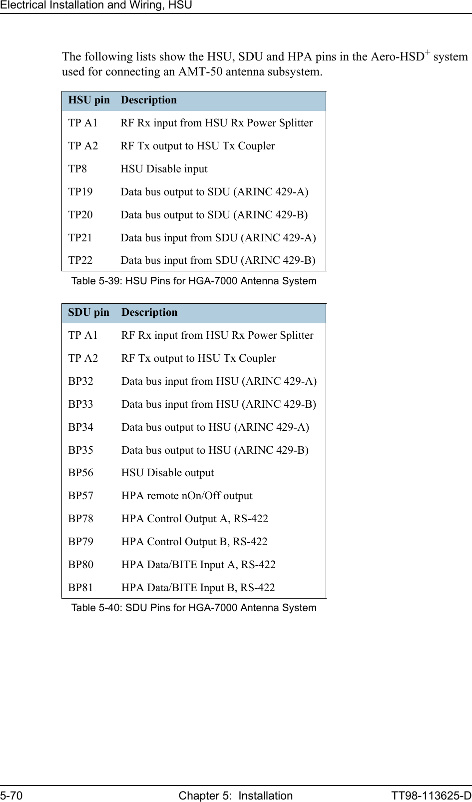
![Electrical Installation and Wiring, HSUTT98-113625-D Chapter 5: Installation 5-715555HSU ARINC 429 Interface (TP19-TP22)The ARINC 429 interface on HSU pins TP19-TP22 is used by the SDU to control the HSU. The HSU operates as a slave to the SDU. The Interface is a 100 kbit/s High Speed ARINC 429 duplex data bus to/from the SDU. For electrical specifications refer to the ARINC 429 standard [6]. HPA ARINC 429 Interface (BP8, BP9, BP13, BP14 on HPA)An ARINC 429 high speed Tx interface and an ARINC 429 low speed Rx interface is used for communication between the HPA and the AMT-50 ACU.HSU Disable (TP8)The SDU uses the HSU Disable input to reset and inhibit the transmitter output signal from the HSU. The electrical specification is defined as for the discrete Weight-On-Wheels input type.HPA pin DescriptionTP1 RF Tx output to DLNATP2 RF Tx input from HSU Tx CouplerBP6 Remote nOn/Off input from SDUBP8 A429 Tx A output to AMT-50 ACUBP9 A429 Tx B output to AMT-50 ACUBP13 A429 Rx1 A input from AMT-50 ACUBP14 A429 Rx1 B input from AMT-50 ACUBP25 Tx Data/BITE Output A, RS-422, to SDUBP26 Tx Data/BITE Output B, RS-422, to SDUBP27 Rx Control Input A, RS-422, from SDUBP28 Rx Control Input B, RS-422, from SDUTable 5-41: HPA Pins for HGA-7000 Antenna System](https://usermanual.wiki/Thrane-and-Thrane-A-S/AERO-HSU/User-Guide-507698-Page-149.png)
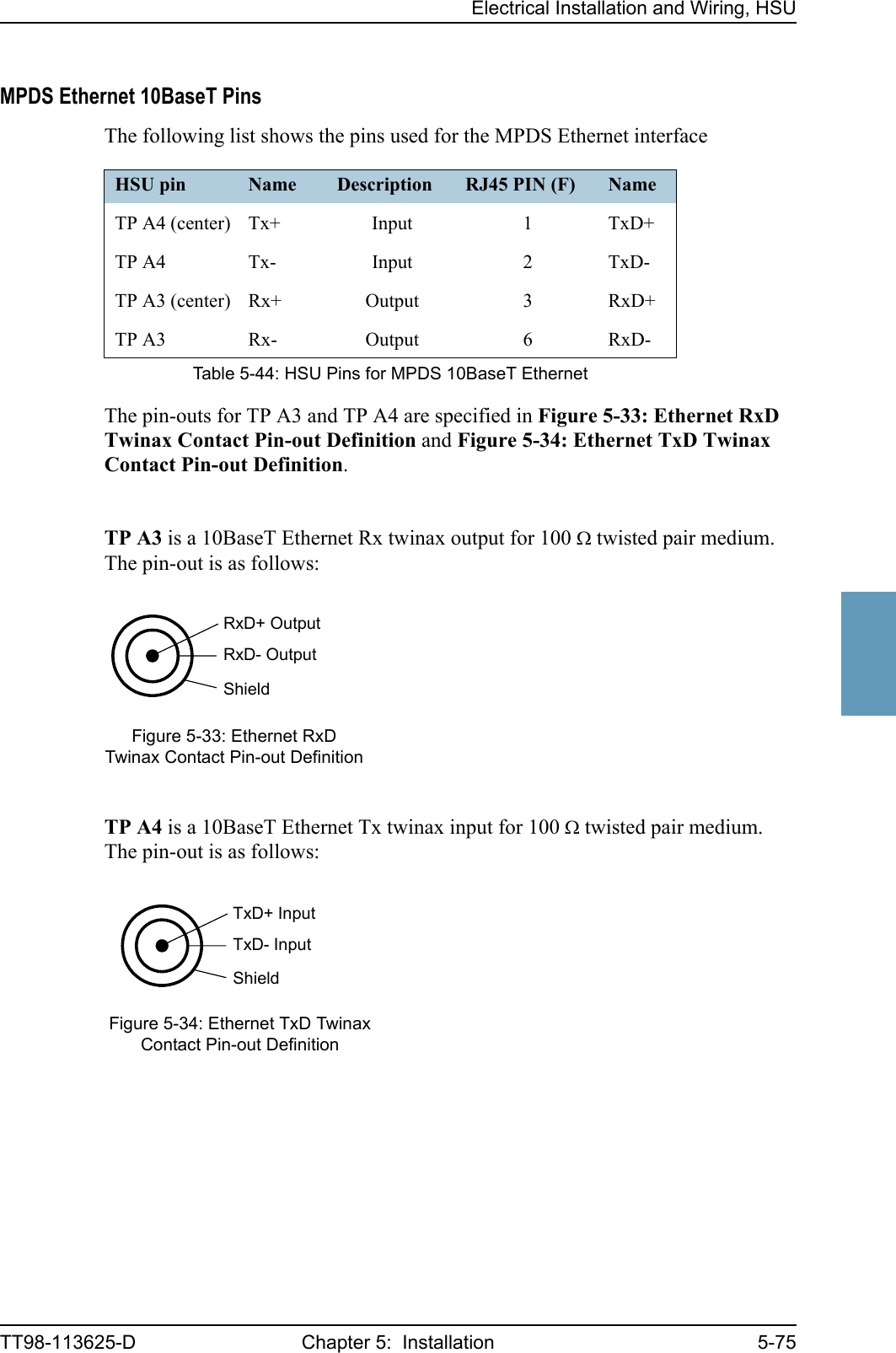
![Electrical Installation and Wiring, HSU5-76 Chapter 5: Installation TT98-113625-DThe 10 Mbit/s Ethernet interface physical layer conforms to [1] (IEEE standard 802.3, Chapter 14: “Twisted Pair medium attachment unit”), except for the connector type. To be compliant with [1], an RJ45 female connector must be used for the user interface. The connector pin assignment must be according to [1] and [2] (ISO8877 ISO/IEC 8877) as shown in Figure 5-35: Ethernet RJ45 Connector and Cable Connection to HSU.The HSU is defined as a DCE or a Hub i.e. TxD is input and RxD is output. Cable Requirements, MPDS Ethernet 10BaseT on HSUThe cable for the MPDS Ethernet 10BaseT interface for the HSU must be a 100 Ω 2-wire twisted and shielded cable.Figure 5-35: Ethernet RJ45 Connector and Cable Connection to HSU.12345678TxD+ TX+ inputn.c.TxD- TX- inputRxD+ RX+ outputn.c.RxD- RX- outputn.c.n.c.RJ45female HSU pinTP A4to DTE100Ω Twinax twistedand shielded pairsHSU (DCE/Hub)12345678HSU pinTP A3](https://usermanual.wiki/Thrane-and-Thrane-A-S/AERO-HSU/User-Guide-507698-Page-154.png)
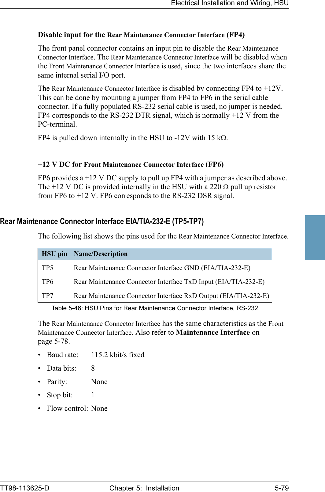
![Electrical Installation and Wiring, HSUTT98-113625-D Chapter 5: Installation 5-775555ISDN PinsThe following list shows the pins used for the ISDN interface.The HSU is configured as the network side of the NT1 interface i.e. Rx is an input and Tx is an output. Please note that this configuration of input and output differs from the configuration of the 10BaseT Ethernet, the MPDS RS-232 interface and RS-232 PC interface input/output.To be compliant with ISO8877 [2] and the ISDN connector specification defined by ITU I.420 [5], an RJ-45 Female Connector must be connected to the four wire ISDN lines from the HSU. The HSU includes an internal 100 Ω termination resistor to support cable lengths longer than 3 meters.The ISDN interface can power supply 4 ISDN phones but supports 8 phones (where 4 of them must have their own power supply). At power hold-up, only power for one phone is available i.e. if more than one phone is connected, the HSU may reset if an incoming call is received, or more than one handset is off-hook, during a power hold-up session. Cable Requirements, ISDNThe cable for the ISDN interface must be a 100 Ω 4-wire shielded cable. The conductors must be twisted in pairs.HSU pin Name Description RJ45 PIN (F) NameTP23 ISDN Rx+ (c) Input 3 Rx+TP24 ISDN Tx+ (d) Output 4 Tx+TP25 ISDN Tx- (e) Output 5 Tx-TP26 ISDN Rx- (f) Input 6 Rx-Table 5-45: HSU Pins for ISDNFigure 5-36: ISDN RJ45 Connector12345678ISDN Rx+ InputISDN Tx+ OutputISDN Tx- OutputISDN Rx- Inputn.c.n.c.n.c.n.c.RJ45 (Female Connector)RJ45female12345678](https://usermanual.wiki/Thrane-and-Thrane-A-S/AERO-HSU/User-Guide-507698-Page-155.png)
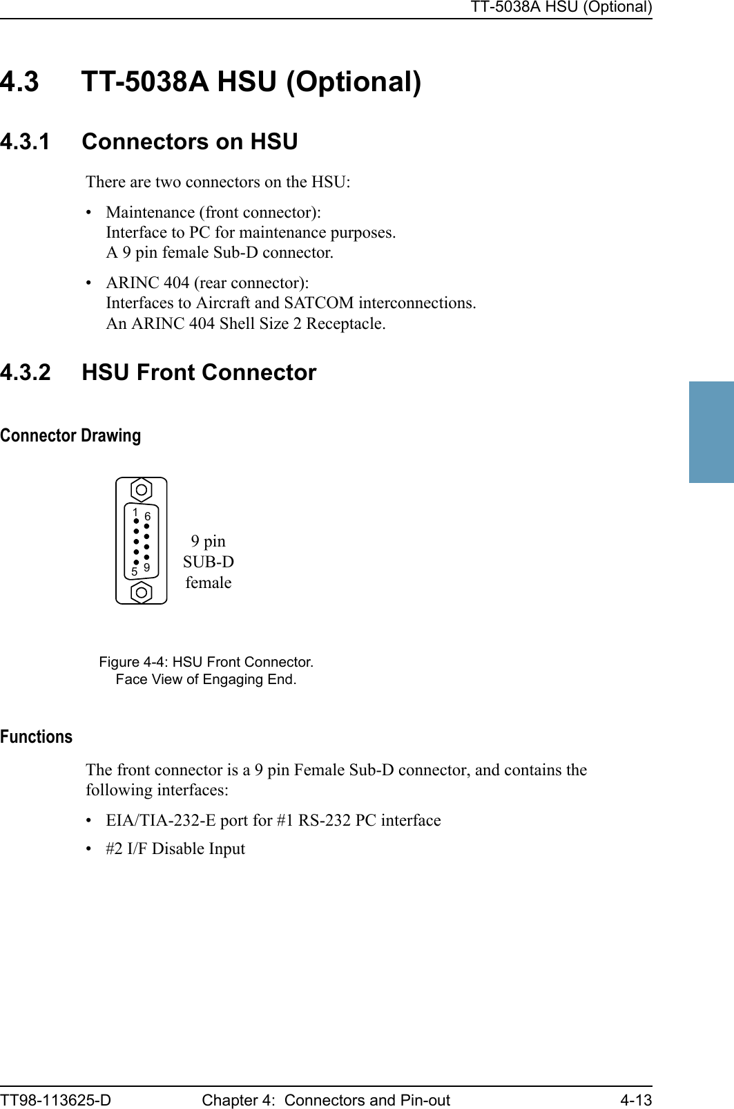
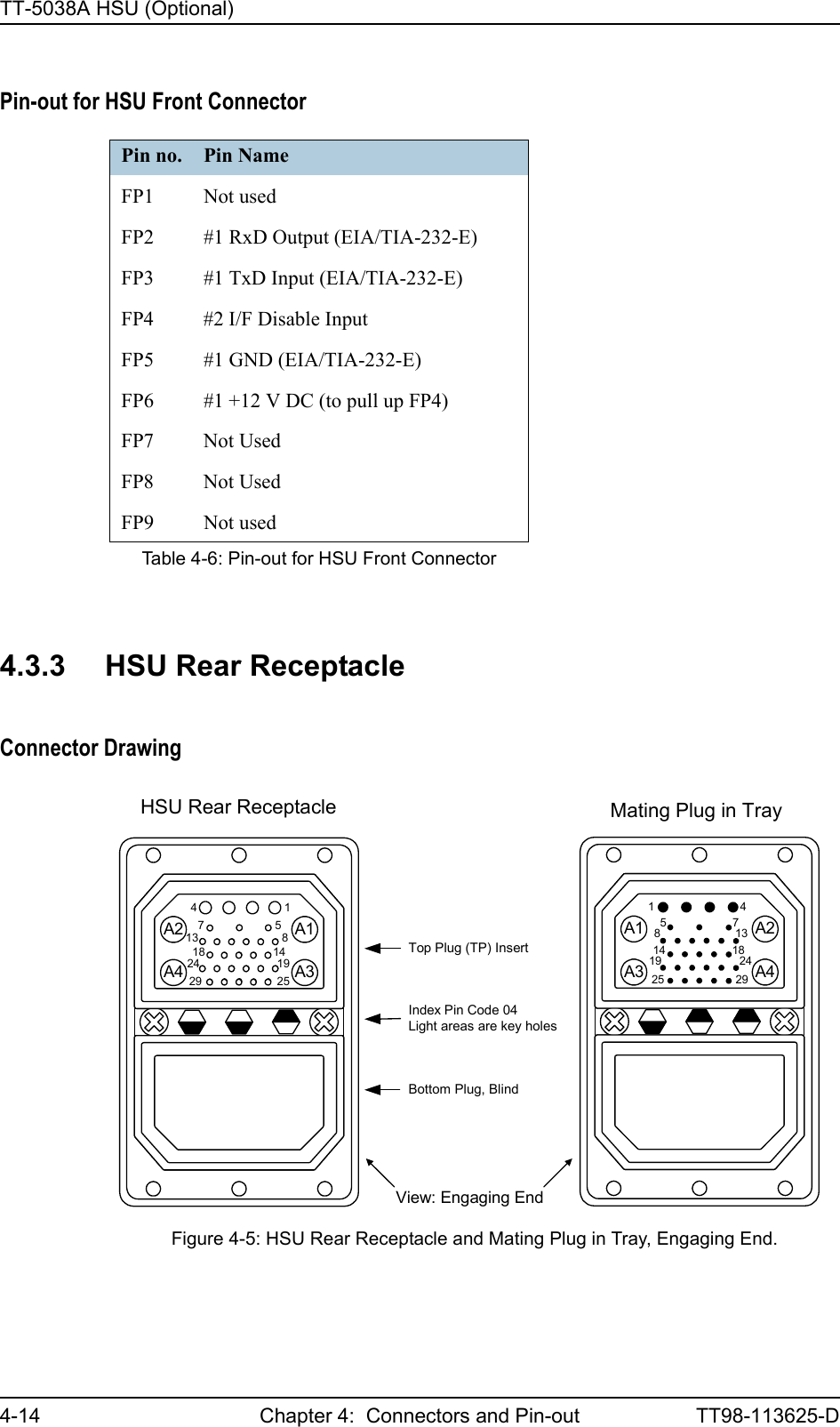
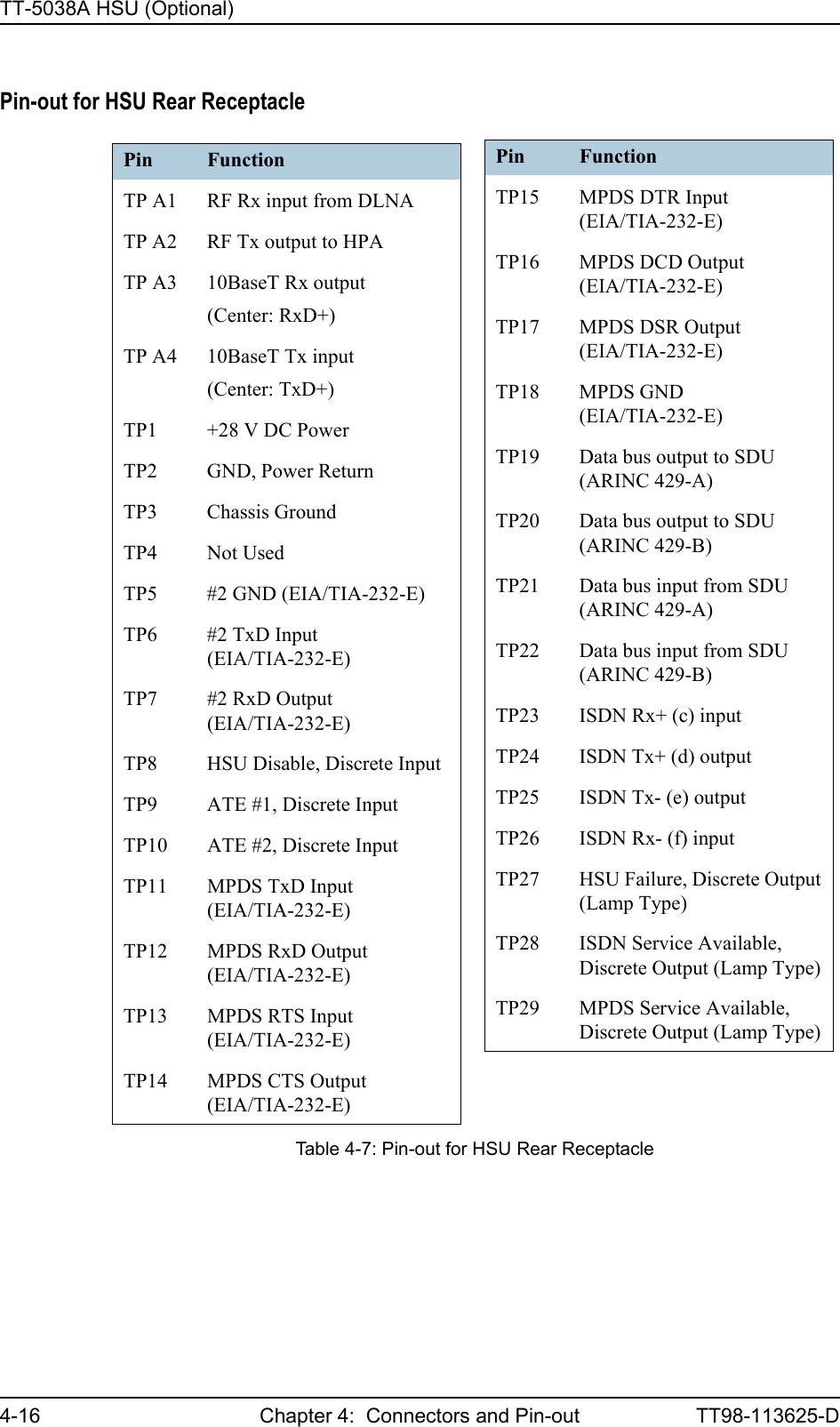
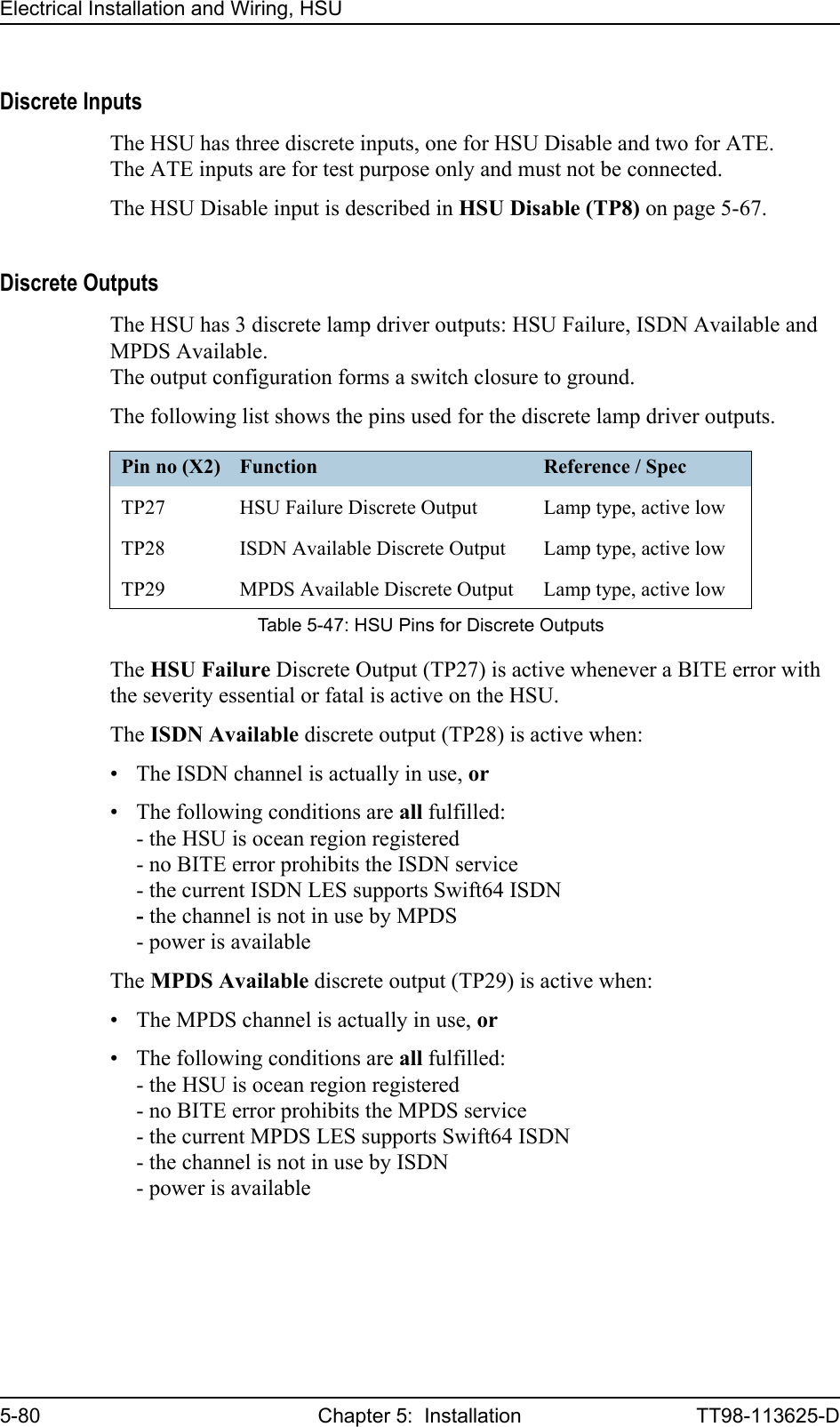
![Electrical Installation and Wiring, HSU5-78 Chapter 5: Installation TT98-113625-D5.4.5 Wiring HSU to Discretes and Maintenance PC InterfaceThe following drawing shows the wiring of the front maintenance interface and discretes and RS-232 PC connection.Maintenance InterfaceThe HSU has two RS-232 PC interfaces for maintenance, one at the front panel connector and one at the rear panel connector. Both interfaces support the EIA/TIA-232-E standard and may also be used as a printer interface. Both interfaces may be used for software upload.The interfaces are configured as DCE on the HSU (i.e. TxD is input and RxD is output). Front Maintenance Connector Interface EIA/TIA-232-E (FP2, FP3, FP5)For information on pin-out for the Front Maintenance Connector interface, see Pin-out for HSU Front Connector on page 4-14.The Front Maintenance Connector Interface has the following characteristics:• Baud rate: 115.2 kbit/s fixed• Data bits: 8• Parity: None• Stop bit: 1• Flow control: NoneFigure 5-37: Wiring HSU to Discretes and RS-232 PC Maintenance InterfacesTT-5038AHSUMaintenancePC #2TP6TP7TP5Rear TxD (EIA/TIA-232-E)Rear GND (EIA/TIA-232-E)Rear RxD (EIA/TIA-232-E)ATE #1 [1] TP9TP10DiscreteOutputsISDN AvailableMPDS AvailableHSU Failure TP27TP28TP29ATE #2 [1]FP2FP3FP4FP5FP6MaintenancePC #1FRONT CONNECTOR (DB9)[1] ATE is for test purpose only; leave unconnected23456Front GND (EIA/TIA-232-E)+12 VDC (to pull up FP4, DSR)Disable Input for Rear I/F (DTR)Front RxD (EIA/TIA-232-E)Front TxD (EIA/TIA-232-E)325DB9FDB9F](https://usermanual.wiki/Thrane-and-Thrane-A-S/AERO-HSU/User-Guide-507698-Page-156.png)
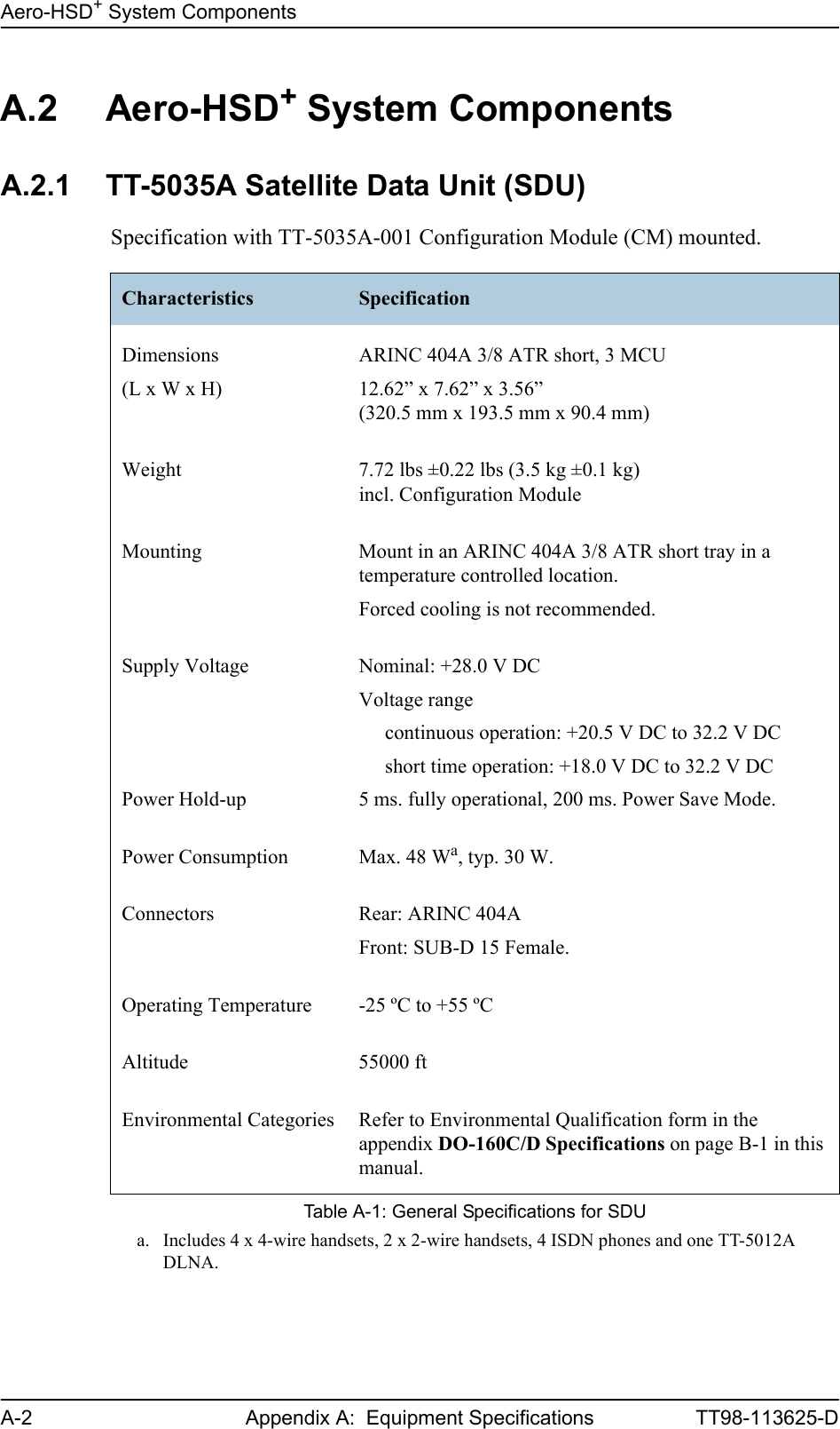
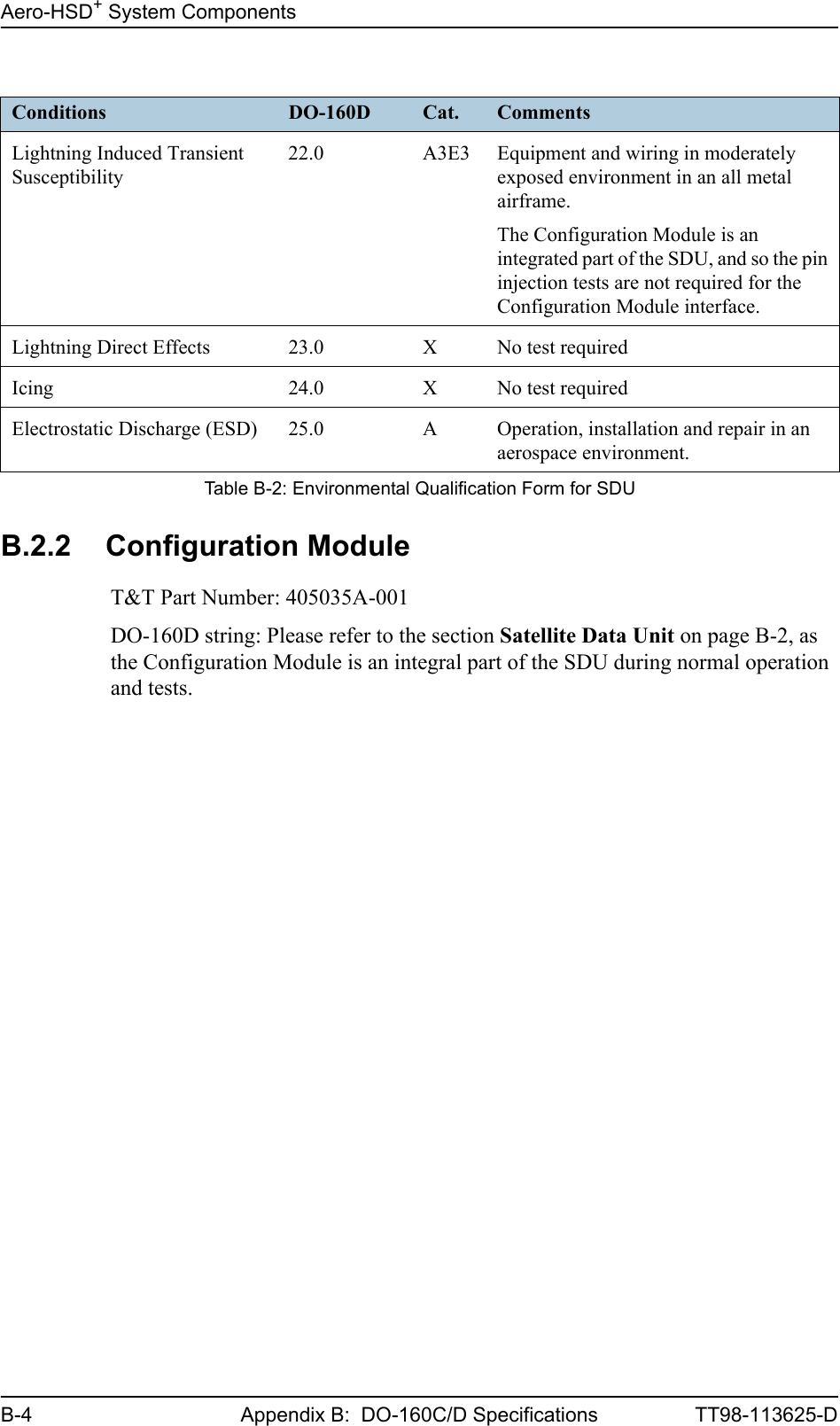
![Aero-HSD+ System ComponentsB-2 Appendix B: DO-160C/D Specifications TT98-113625-DB.2 Aero-HSD+ System ComponentsB.2.1 Satellite Data Unit T&T Part Number: 405035ADO-160D string: [(A1)(F1)X]CAB[(S2B2)(SM)]EXXXXXZ[A()B]A[A()B]Z[RR]M[A3E3]XXARTCA/DO-160D Change NumbersChange Number Date of Issue Title SectionChange No. 1 Dec. 14, 2000 VibrationRadio Frequency Susceptibility8.020.0Change No. 2 June 12, 2001 Power InputAudio Frequency Conducted Susceptibility - Power Inputs16.018.0Table B-1: RTCA/DO-160D Change Numbers, SDUConditions DO-160D Cat. CommentsTemperature and Altitude 4.0 A1 and F1Installation in controlled temperature locations and inside or outside pressurized locations.Low Temperature 4.5.1 Min. operating low temperature: -25°CHigh Temperature 4.5.2 & 4.5.3 Max. operating high temperature: +55°CIn-Flight Loss of Cooling 4.5.4 X Forced cooling is not recommended.Altitude 4.6.1 Max. altitude: 55000 ftDecompression 4.6.2 Decompression at 55000 ftOverpressure 4.6.3 Overpressure at -15000ftTemperature Variation 5.0 C Installation within controlled temperature locations: 2°/min.Humidity 6.0 A Standard Humidity: 95% relative humidity at 38°C to 50°C for 48 hours.Installation within environmentally controlled zones.Operational Shocks and Crash Safety7.0 B Equipment tested to: Standard operational shocks and crash safety.Table B-2: Environmental Qualification Form for SDU](https://usermanual.wiki/Thrane-and-Thrane-A-S/AERO-HSU/User-Guide-507698-Page-214.png)
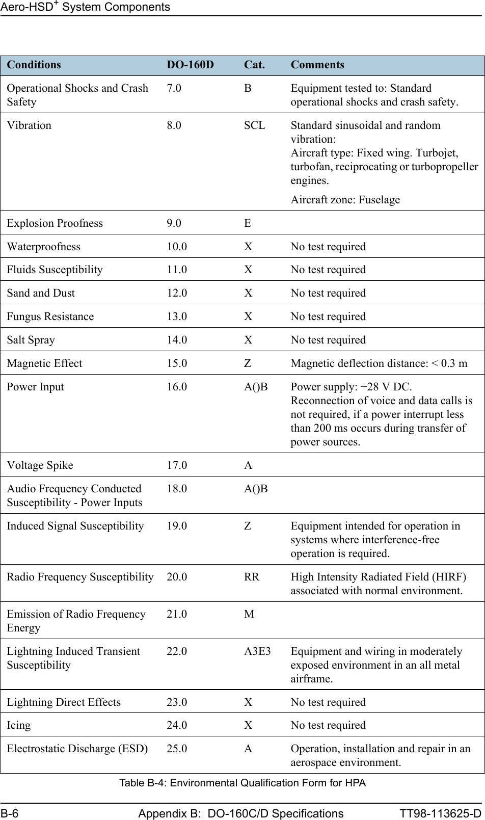
![Aero-HSD+ System ComponentsTT98-113625-D Appendix B: DO-160C/D Specifications B-5BBBBB.2.3 High Power AmplifierT&T Part Number: 405014ADO-160D string: [(A2)(F2)Z]BBB[SCL]EXXXXXZ[A()B]A[A()B]Z[RR]M[A3E3]XXARTCA/DO-160D Change NumbersChange Number Date of Issue Title SectionChange No. 1 Dec. 14, 2000 VibrationRadio Frequency Susceptibility8.020.0Change No. 2 June 12, 2001 Power InputAudio Frequency Conducted Susceptibility - Power Inputs16.018.0Table B-3: RTCA/DO-160D Change Numbers, HPAConditions DO-160D Cat. CommentsTemperature and Altitude 4.0 A2 and F2Installation in non-controlled temperature locations and inside or outside pressurized locations.Low Temperature 4.5.1 Min. operating low temperature: -55°CHigh Temperature 4.5.2 & 4.5.3 Max. operating high temperature: +70°CIn-Flight Loss of Cooling 4.5.4 Z Continuous operation at 40°C, tested with internal fan turned off.Use the recommended tray and leave at least 1 inch (25 mm) of free space above and below the HPA, to allow free airflow.The HPA is overheat protected.External forced cooling is not recommended.Altitude 4.6.1 Max. altitude: 55000 ftDecompression 4.6.2 Decompression at 55000 ftOverpressure 4.6.3 Overpressure at -15000 ftTemperature Variation 5.0 B Installation within non-temperature-controlled location: 5°C/min.Humidity 6.0 B Severe humidity: 95% relative humidity at 38°C to 65°C for 240 hours.Installation within non-environmentally controlled zones.Table B-4: Environmental Qualification Form for HPA](https://usermanual.wiki/Thrane-and-Thrane-A-S/AERO-HSU/User-Guide-507698-Page-217.png)
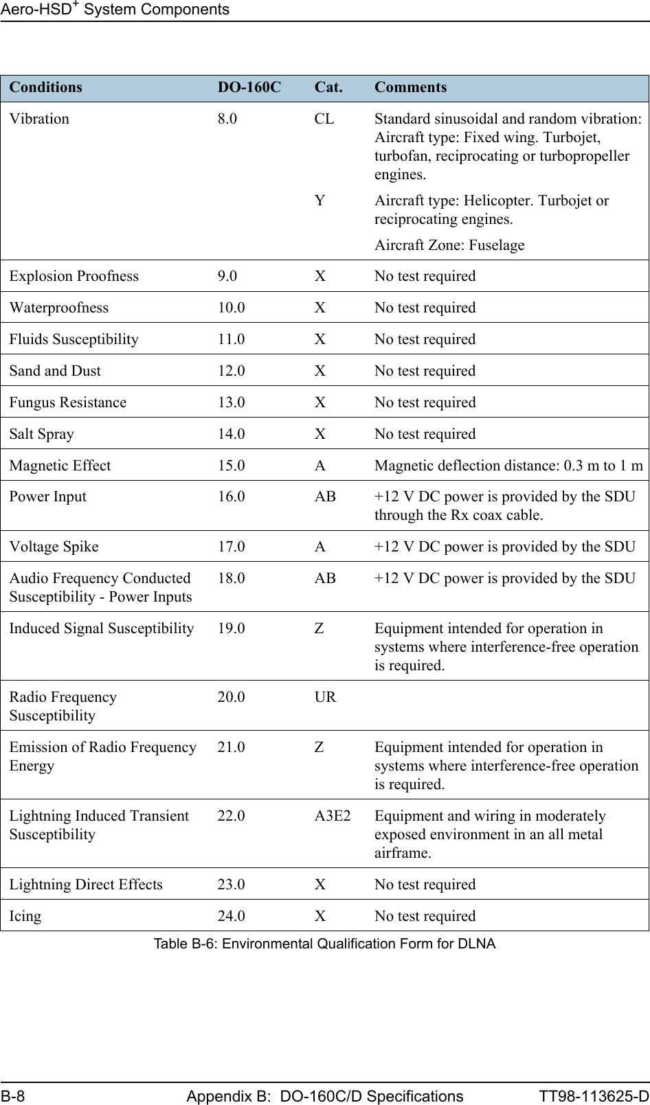
![Aero-HSD+ System ComponentsTT98-113625-D Appendix B: DO-160C/D Specifications B-7BBBBB.2.4 Diplexer and Low Noise AmplifierT&T Part Number: 405012A-THRDO-160C string: [A2F2]-BA[CLY]XXXXXXA[AB]A[AB]Z[UR]ZA3E2XXRTCA/DO-160C Change NumbersChange Number Date of Issue Title SectionChange No. 2 June 19, 1992 Lightning Induced Transient Susceptibility 22.0Change No. 3 May 13, 1993 Radio Frequency Susceptibility 20.0Table B-5: RTCA/DO-160C Change Numbers, DLNAConditions DO-160C Cat. CommentsTemperature and Altitude 4.0 A2 and F2Installation in non-controlled temperature locations inside or outside pressurized locations.Low Temperature 4.5.1 Min. operating low temperature: -55°CHigh Temperature 4.5.2 & 4.5.3 Max. operating high temperature: +70°CIn-Flight Loss of Cooling 4.5.4 - No forced cooling required.Altitude 4.6.1 Max. altitude: 55000 ftDecompression 4.6.2 Decompression at 55000 ftOverpressure 4.6.3 Overpressure at -15000 ftTemperature Variation 5.0 B Installation within partially or non-controlled temperature locations: 5°C/min.Humidity 6.0 A Standard Humidity: 95% relative humidity at 38°C to 50°C for 48 hours.Installation within environmentally controlled zonesOperational Shocks and Crash SafetyOperational ShockCrash Safety7.07.27.3YesYesYesEquipment tested to: Standard operational shocks and crash safety.Table B-6: Environmental Qualification Form for DLNA](https://usermanual.wiki/Thrane-and-Thrane-A-S/AERO-HSU/User-Guide-507698-Page-219.png)
![Aero-HSD+ System ComponentsTT98-113625-D Chapter B: DO-160C/D Specifications B-9BBBBB.2.5 High Speed Data Unit (Optional)T&T Part Number: 405038ADO-160D string: [(A1)(F1)X]CBB[(S2B2)(SM)]EXXXXXZ[A()B]A[A()B]Z[RR]M[A3E3]XXAFor the environmental qualification form for the HSU, please refer to the section Satellite Data Unit on page B-2, as the forms are identical for the SDU and the HSU, except for:Humidity, DO-160 section 6.0, tested to category B, Severe Humidity Environment (240 hours, 65°C, 95% humidity).](https://usermanual.wiki/Thrane-and-Thrane-A-S/AERO-HSU/User-Guide-507698-Page-221.png)
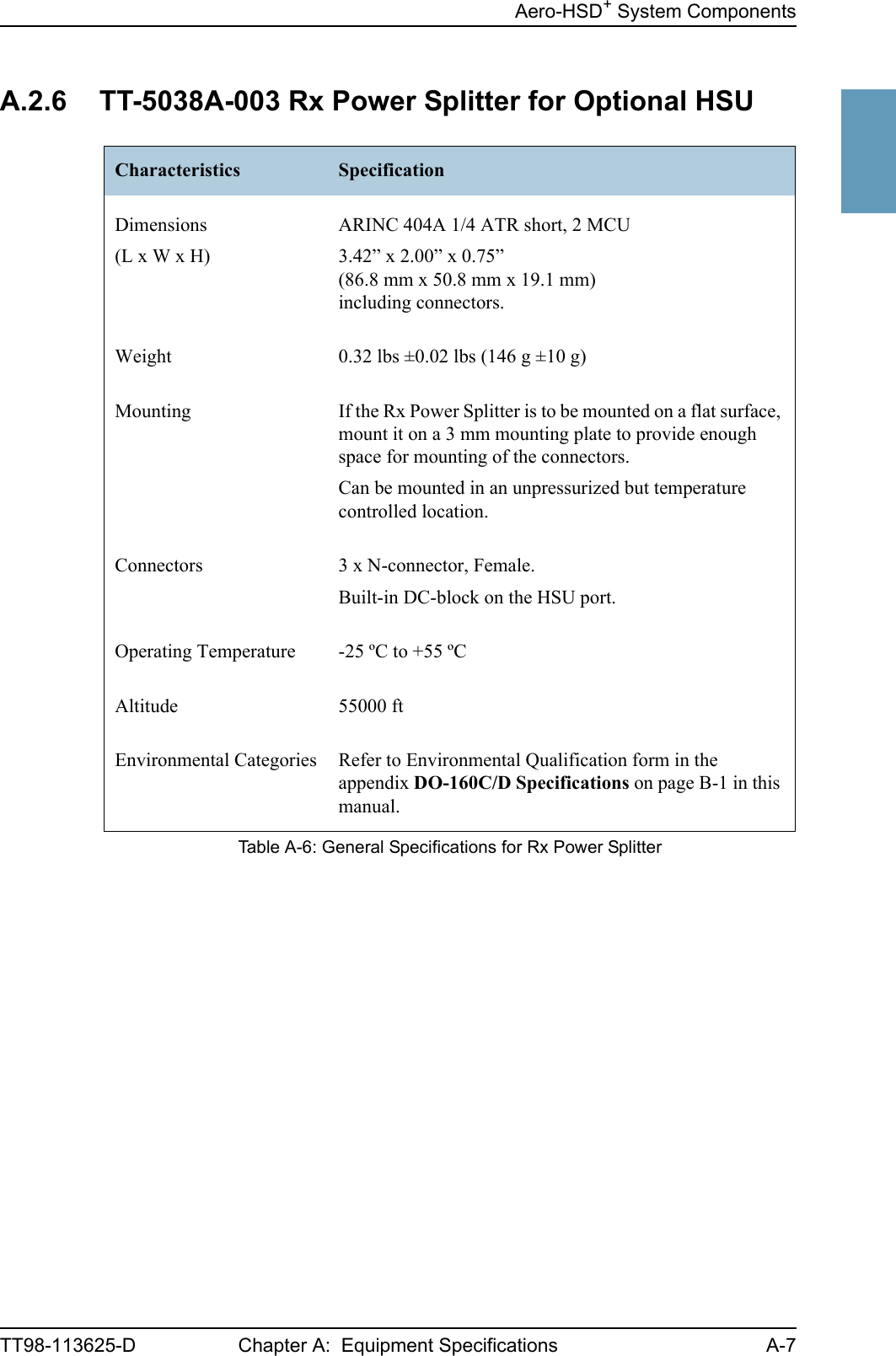
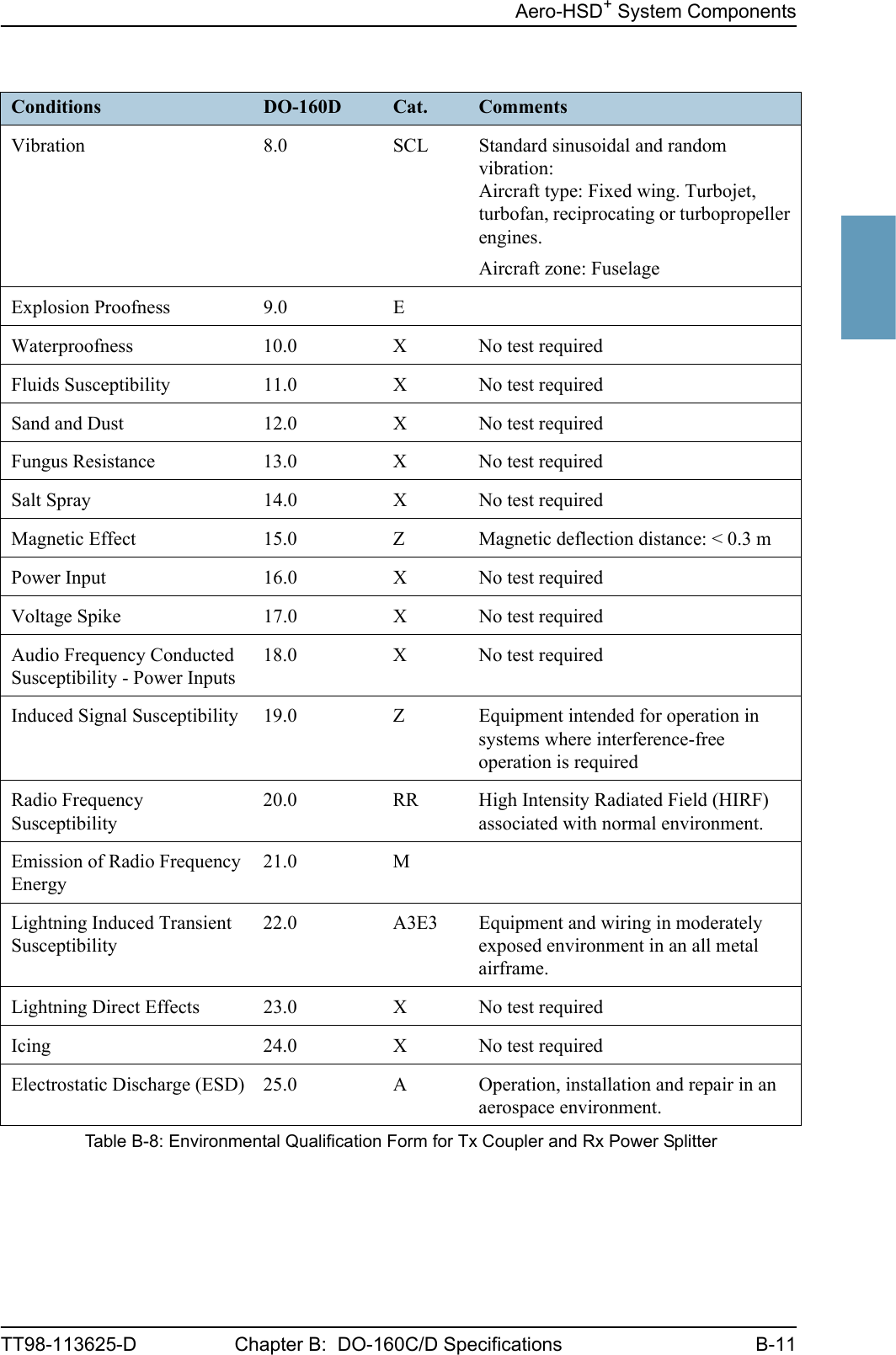
![Aero-HSD+ System ComponentsB-10 Chapter B: DO-160C/D Specifications TT98-113625-DB.2.6 Tx Coupler and Rx Power Splitter for Optional HSUT&T Part Numbers: 405038A-002 and 405038A-003DO-160D string: [(A1)(F1)X]CBB[SCL]EXXXXXZXXXZ[RR]M[A3E3]XXARTCA/DO-160D Change NumbersChange Number Date of Issue Title SectionChange No. 1 Dec. 14, 2000 VibrationRadio Frequency Susceptibility8.020.0Change No. 2 June 12, 2001 Power InputAudio Frequency Conducted Susceptibility - Power Inputs16.018.0Table B-7: RTCA/DO-160D Change Numbers, Tx Coupler and Rx Power SplitterConditions DO-160D Cat. CommentsTemperature and Altitude 4.0 A1 and F1Installation in controlled temperature locations and inside or outside pressurized locations.Low Temperature 4.5.1 Min. operating low temperature: -25°CHigh Temperature 4.5.2 & 4.5.3 Max. operating high temperature: +55°CIn-Flight Loss of Cooling 4.5.4 X Forced cooling is not recommended.Altitude 4.6.1 Max. altitude: 55000 ftDecompression 4.6.2 Decompression at 55000 ftOverpressure 4.6.3 Overpressure at -15000 ftTemperature Variation 5.0 C Installation within controlled temperature locations: 2°/min.Humidity 6.0 B Severe humidity: 95% relative humidity at 38°C to 65°C for 240 hours.Installation within non-environmentally controlled zones.Operational Shocks and Crash Safety7.0 B Equipment tested to: Standard operational shocks and crash safety.Table B-8: Environmental Qualification Form for Tx Coupler and Rx Power Splitter](https://usermanual.wiki/Thrane-and-Thrane-A-S/AERO-HSU/User-Guide-507698-Page-222.png)
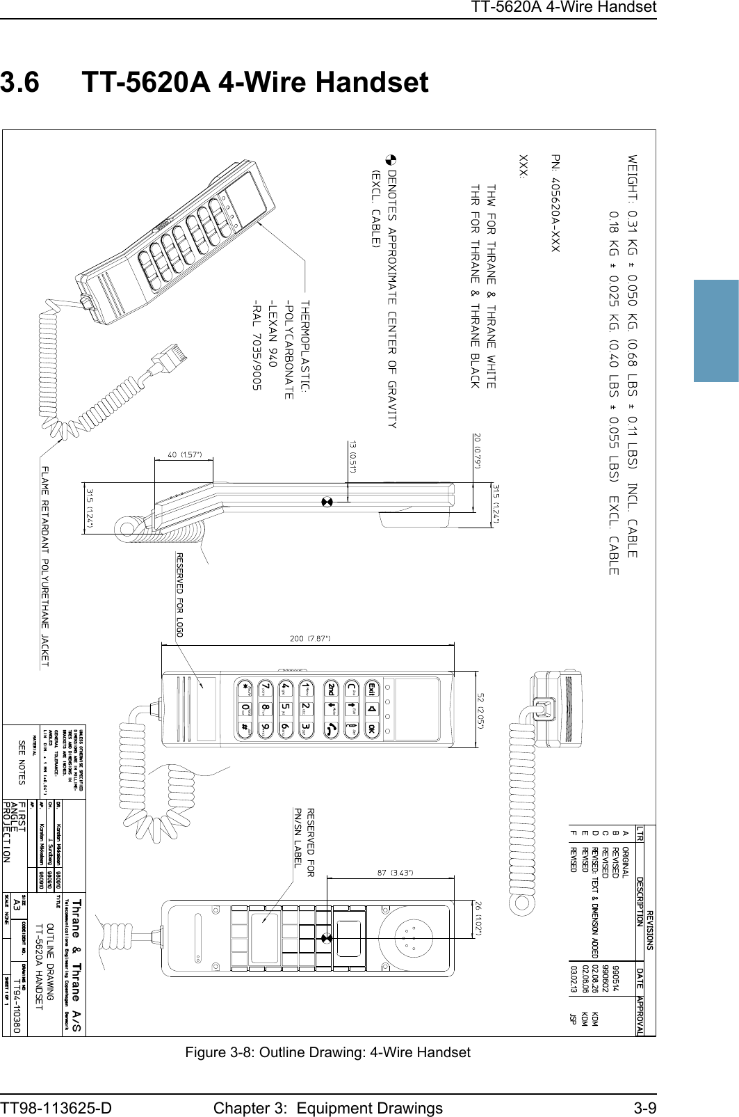
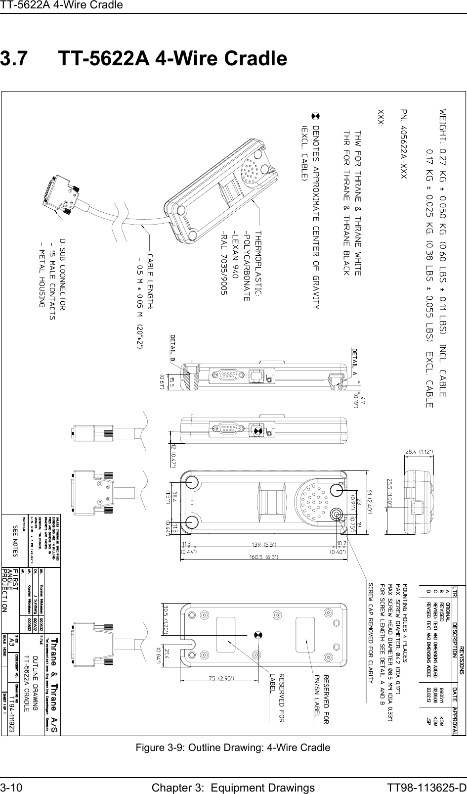
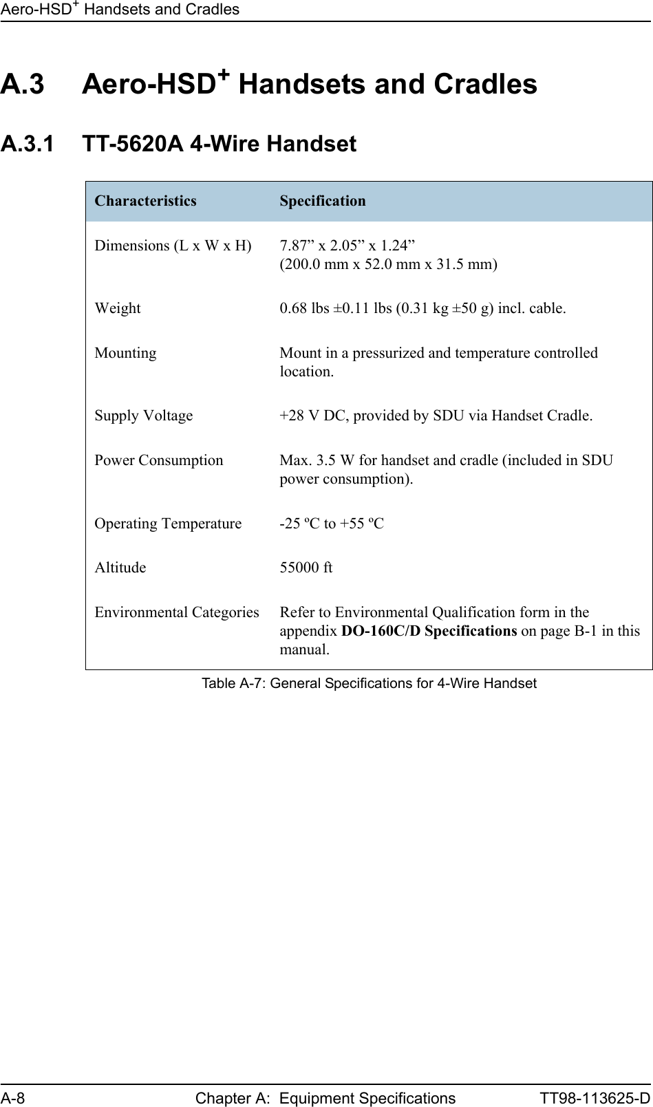
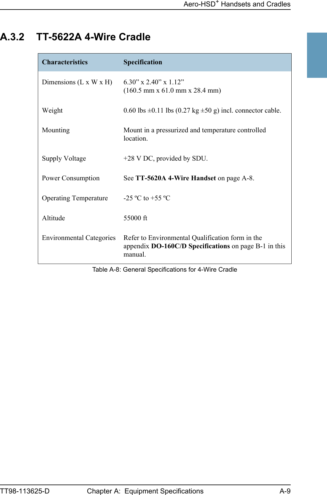
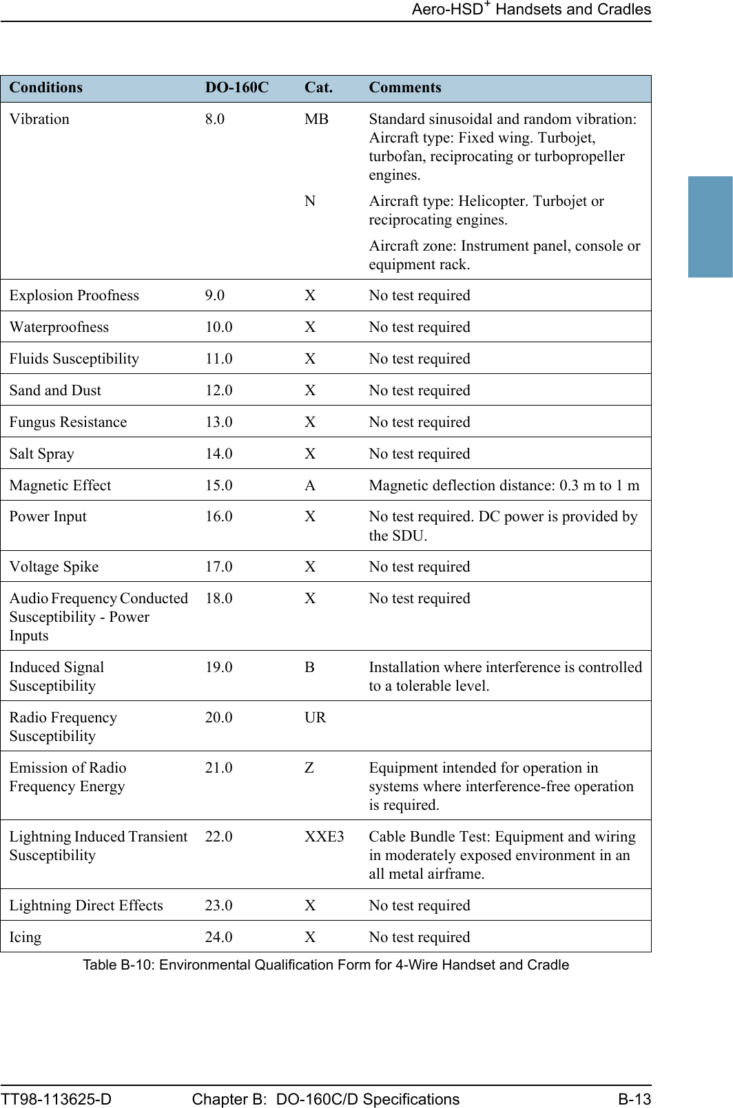
![Aero-HSD+ Handsets and CradlesB-12 Chapter B: DO-160C/D Specifications TT98-113625-DB.3 Aero-HSD+ Handsets and CradlesB.3.1 4-Wire Handset and 4-Wire CradleT&T Part Number: 405620A-THW / 405620A-THR / 405622A-THW / 405622A-THRDO-160C String: A1-BA[MNB]XXXXXXAXXXB[UR]ZXXE3XXRTCA/DO-160C Change NumbersChange Number Date of Issue Title SectionChange No. 2 June 19, 1992 Lightning Induced Transient Susceptibility 22.0Change No. 3 May 13, 1993 Radio Frequency Susceptibility 20.0Table B-9: RTCA/DO-160C Change Numbers, 4-wire Handset and CradleConditions DO-160C Cat. CommentsTemperature and Altitude 4.0 A1 Installation in controlled temperature and pressurized location.Low Temperature 4.5.1 Min. operating low temperature: -25°CHigh Temperature 4.5.2 & 4.5.3 Max. operating high temperature: +55°CIn-Flight Loss of Cooling 4.5.4 - No forced cooling required.Altitude 4.6.1 Max. altitude: 55000 ft Decompression 4.6.2 Decompression at 55000 ftOverpressure 4.6.3 Overpressure at -15000 ftTemperature Variation 5.0 B Installation within partially or non-controlled temperature locations: 5°C/min.Humidity 6.0 A Standard Humidity: 95% relative humidity at 38°C to 50°C for 48 hours.Installation within environmentally controlled zonesOperational Shocks and Crash SafetyOperational ShockCrash Safety7.07.27.3YesYesYesEquipment tested to: Standard operational shocks and crash safety.Table B-10: Environmental Qualification Form for 4-Wire Handset and Cradle](https://usermanual.wiki/Thrane-and-Thrane-A-S/AERO-HSU/User-Guide-507698-Page-224.png)
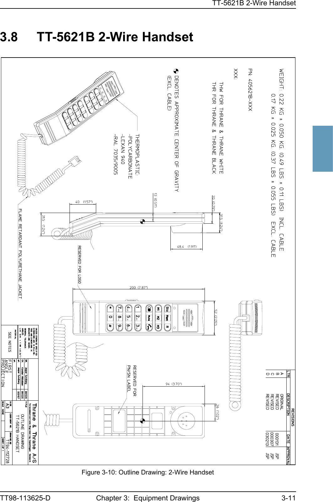
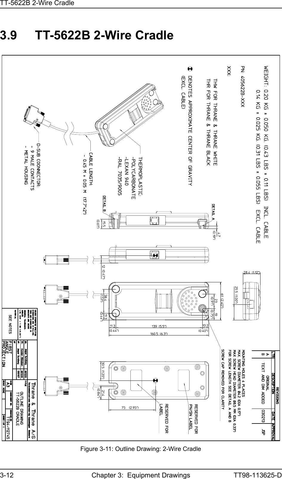
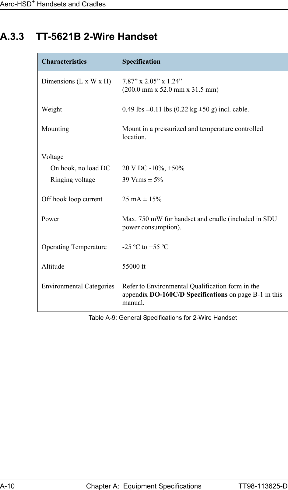
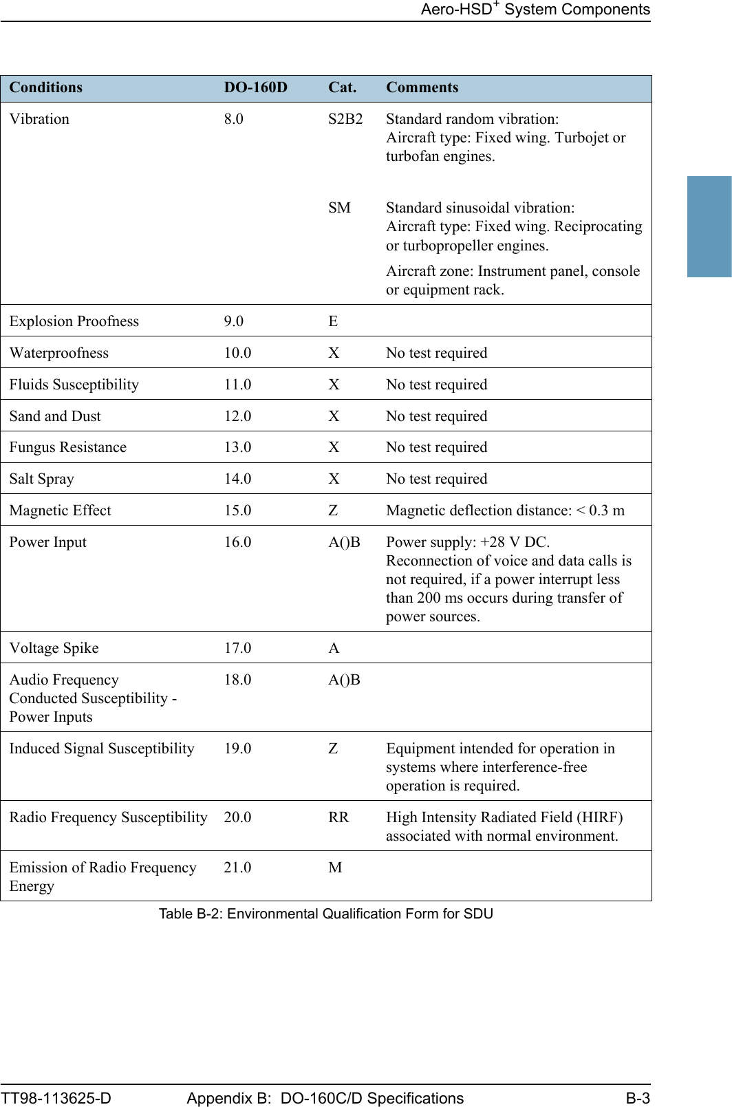
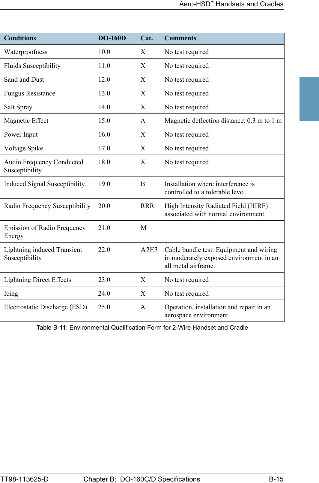
![Aero-HSD+ Handsets and CradlesB-14 Chapter B: DO-160C/D Specifications TT98-113625-DB.3.2 2-Wire Handset and 2-Wire CradleT&T Part Number: 405621B-THW / 405621B-THR / 405622B-THW / 405622B-THRDO-160D String: [A1X]CAB[(SMB2)(SM)(UFF1)]XXXXXXAXXXB[RRR]M[A2E3]XXARTCA/DO-160D Change Numbers: Original DO-160D. Date of issue: July 29, 1997Conditions DO-160D Cat. CommentsTemperature and Altitude 4.0 A1 Installation in controlled temperature and pressurized location.Low Temperature 4.5.1 Min. operating low temperature: -25°CHigh Temperature 4.5.2 & 4.5.3 Max. operating high temperature: +55°CIn-Flight Loss of Cooling 4.5.4 X No forced cooling required.Altitude 4.6.1 Max. altitude: 55000 ftDecompression 4.6.2 Decompression at 55000 ftOverpressure 4.6.3 Overpressure test at -15000 ftTemperature Variation 5.0 C Installation within controlled temperature locations: 2°/min.Humidity 6.0 A Standard Humidity: 95% relative humidity at 38°C to 50°C for 48 hours.Installation within environmentally controlled zones.Operational Shocks and Crash Safety7.0 B Equipment tested to: Standard operational shocks and crash safety.Vibration 8.0 S2B2SMUFF1Standard random vibration:Aircraft type: Fixed wing. Turbojet or turbofan engines.Standard sinusoidal vibration:Aircraft type: Fixed wing. Reciprocating or turbopropeller engines.Robust Sine-on-Random vibration:Aircraft type: Helicopter. Turbojet or reciprocating engines.Aircraft zone: Instrument panel, console or equipment rack.Explosion Proofness 9.0 X No test requiredTable B-11: Environmental Qualification Form for 2-Wire Handset and Cradle](https://usermanual.wiki/Thrane-and-Thrane-A-S/AERO-HSU/User-Guide-507698-Page-226.png)
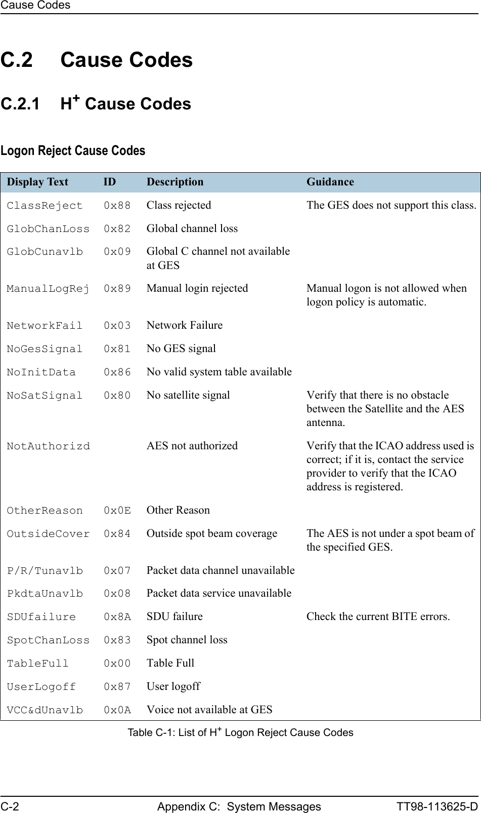
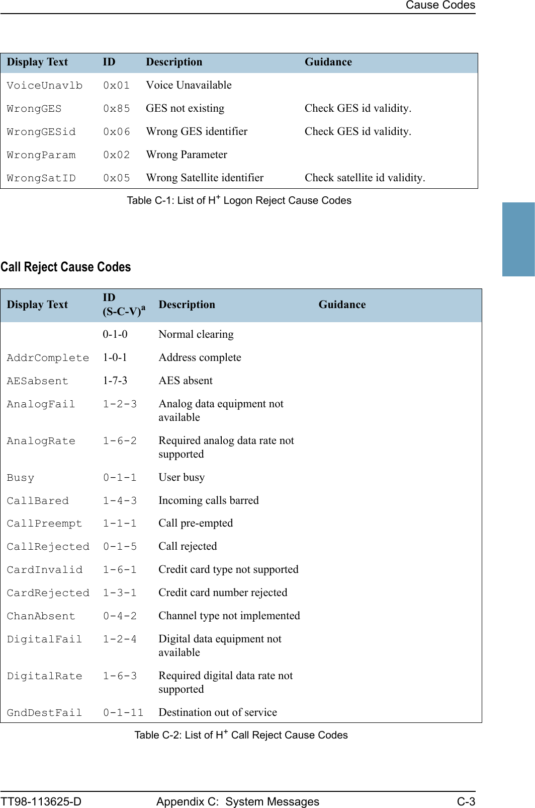
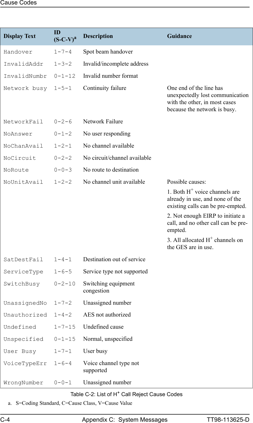
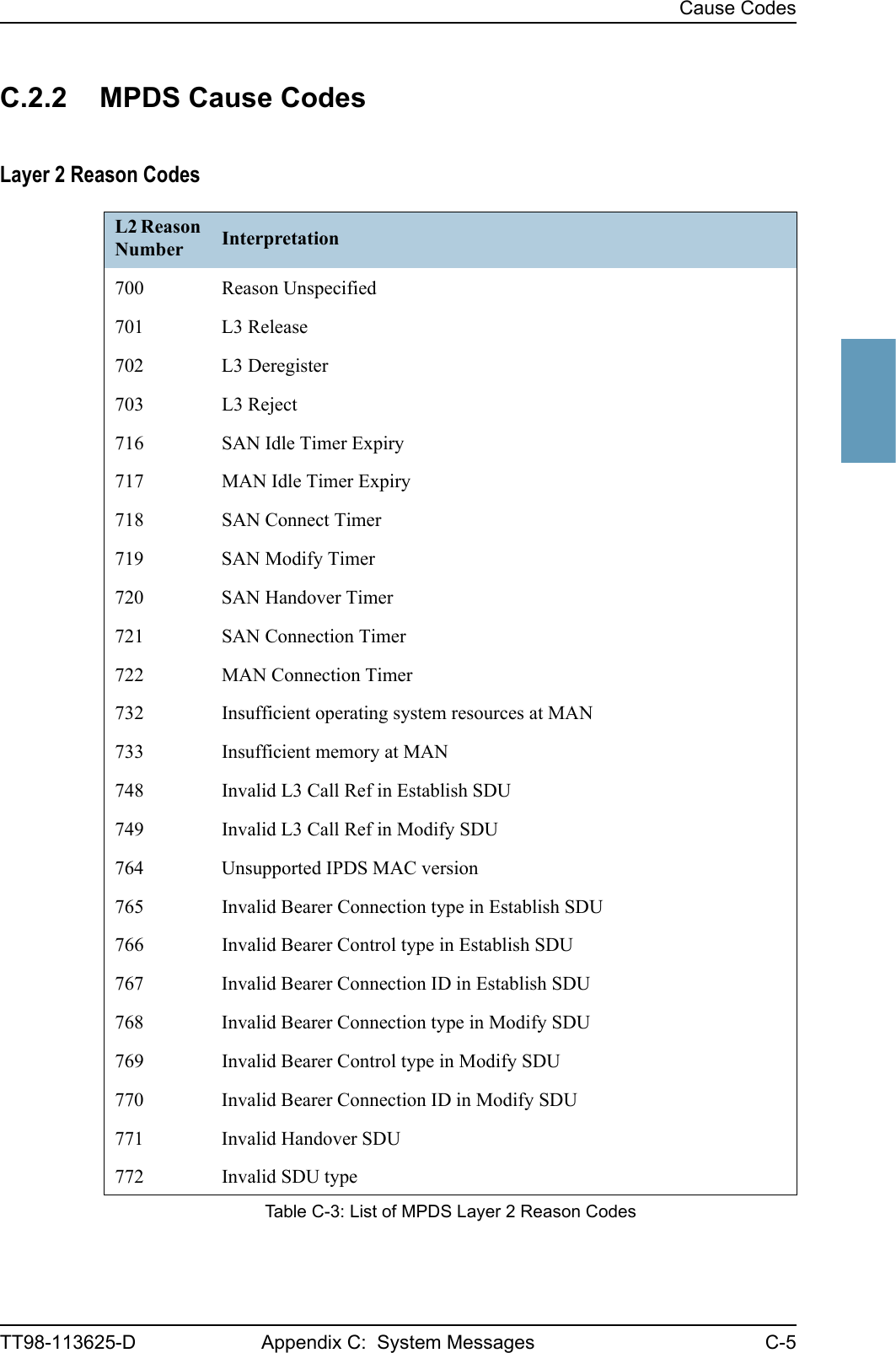
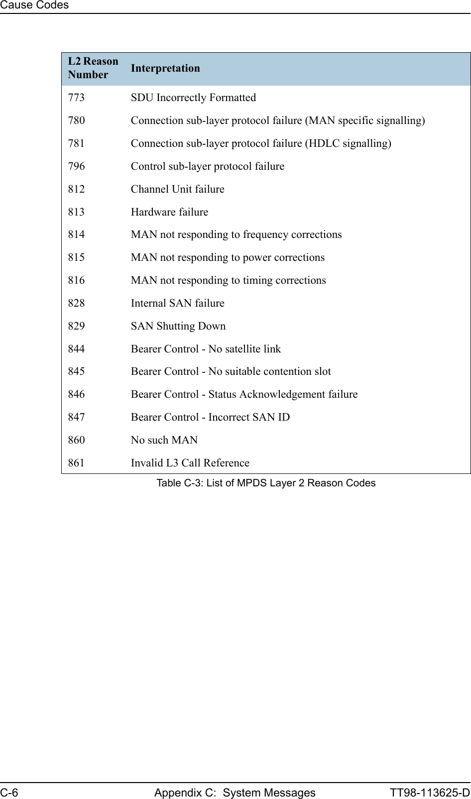
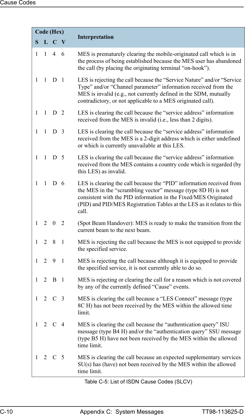
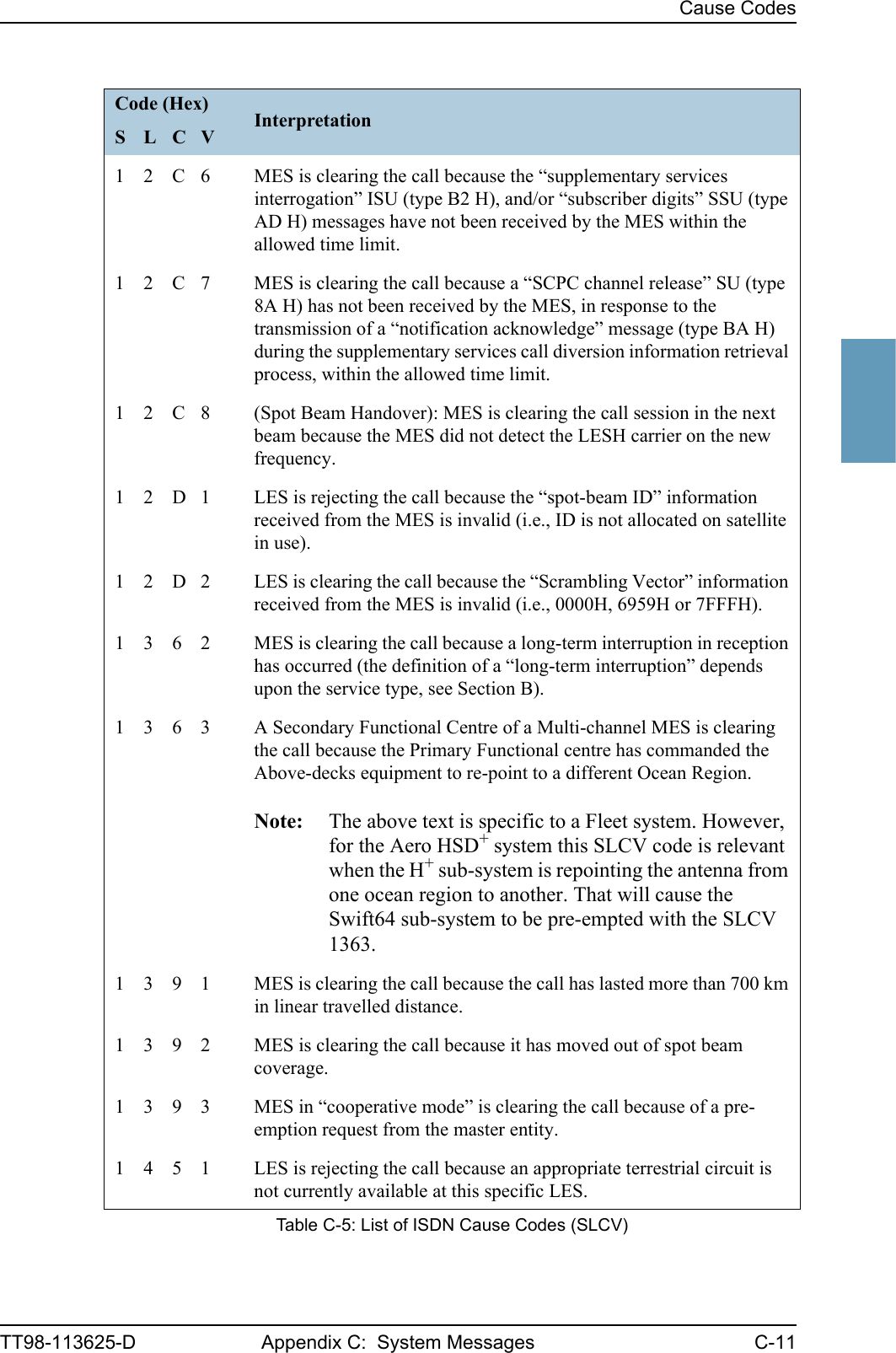
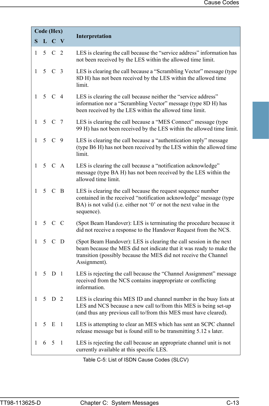
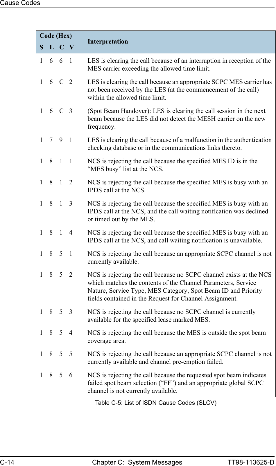
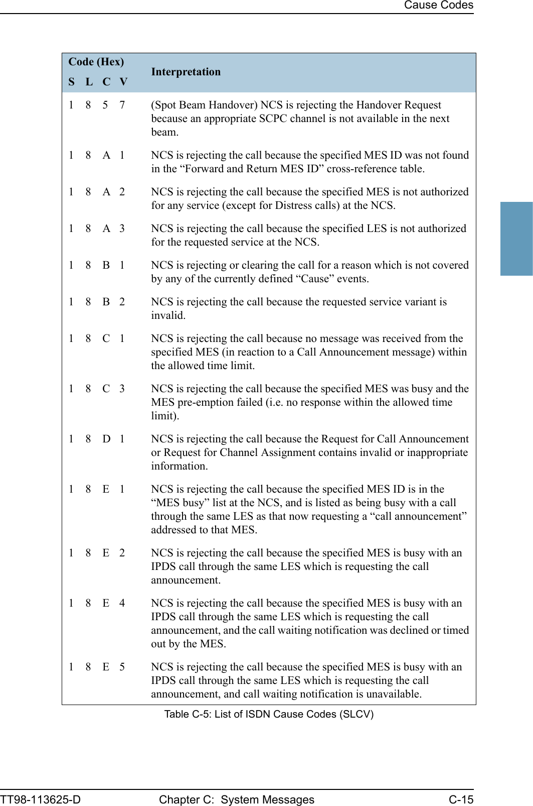
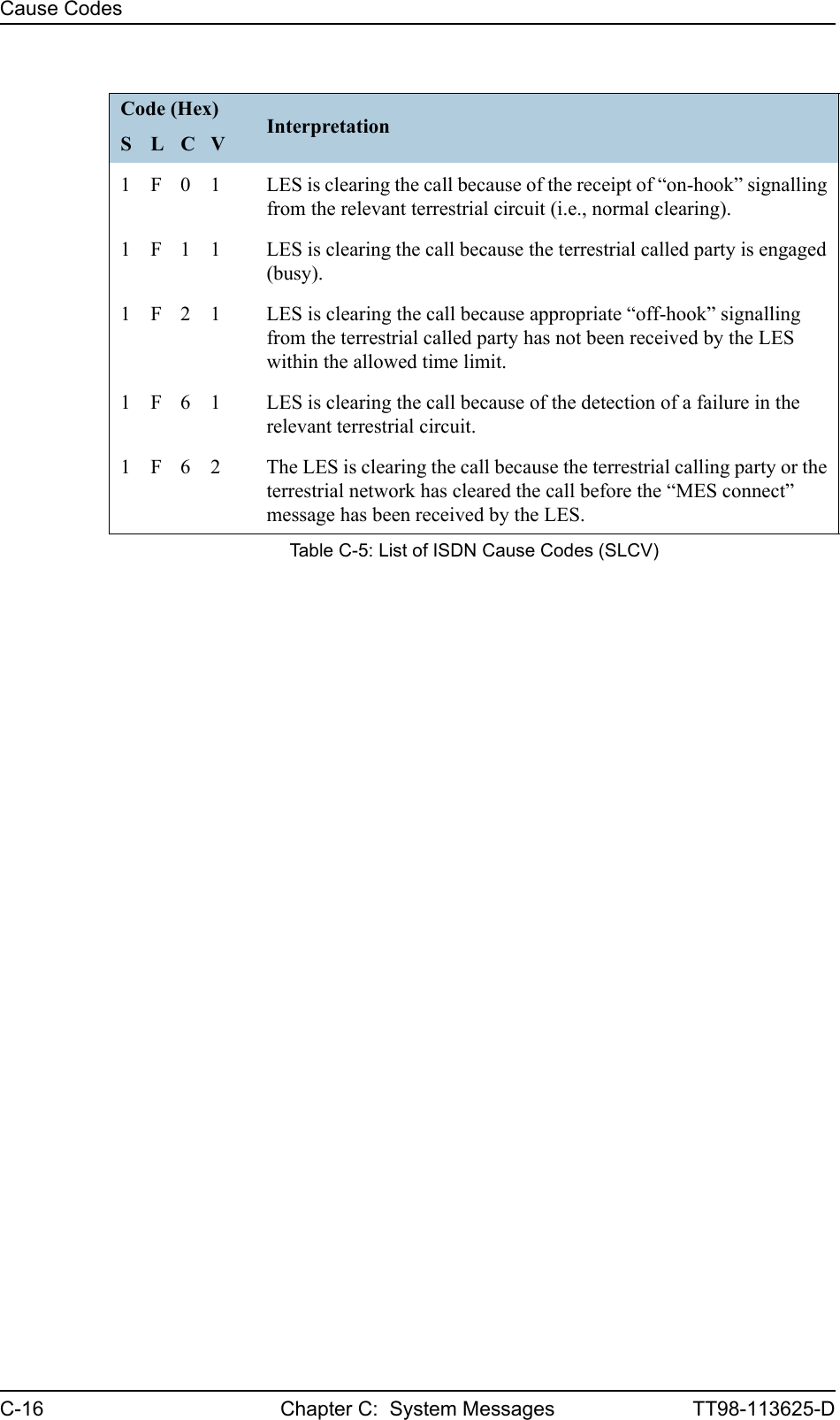
![Cause CodesC-12 Appendix C: System Messages TT98-113625-D1 4 5 2 LES is rejecting the call because an appropriate channel unit and associated terrestrial circuit are not currently available at this LES. [This “cause” is only utilized when there is a permanent “one-to-one” connection between appropriate channel units and their terrestrial circuits].1 5 0 2 (Spot Beam Handover): LES is ready to make the transition from the current beam to the next beam and is clearing the call session in the current beam (normal clear).1 5 5 1 LES is rejecting the call because an appropriate satellite channel is not currently available at this specific LES.1 5 8 1 LES is rejecting the call because the requested service is not provided by this specific LES.1 5 9 1 LES is rejecting the call because the requested service is temporarily not available at this specific LES.1 5 A 1 LES is rejecting the call because the specified MES is not authorized for any service at this specific LES.1 5 A 2 LES is rejecting the call because the specified MES is not authorized to use specific requested service via this specific LES.1 5 A 3 LES is clearing the call because the “credit card data” information received from the MES has been rejected by the credit card authorization process.1 5 A 4 LES is clearing the call because the data received from the MES in the “authentication reply” message (type B6 H) has been declared “invalid” by the LES authentication process.1 5 A 5 LES is rejecting the call because the specified PID is not authorized for any service at this specific LES.1 5 A 6 LES is rejecting the call because the specified PID is not authorized to use specific requested service via this specific LES.1 5 A 7 LES is clearing the call because the service address received from the MES is not authorized for the requested priority.1 5 B 1 LES is rejecting or clearing the call for a reason which is not covered by any of the currently defined “Cause” events.1 5 C 1 LES is rejecting the call because an appropriate “Channel Assignment” message has not been received by the LES within the allowed time limit.Code (Hex) InterpretationS L C VTable C-5: List of ISDN Cause Codes (SLCV)](https://usermanual.wiki/Thrane-and-Thrane-A-S/AERO-HSU/User-Guide-507698-Page-240.png)
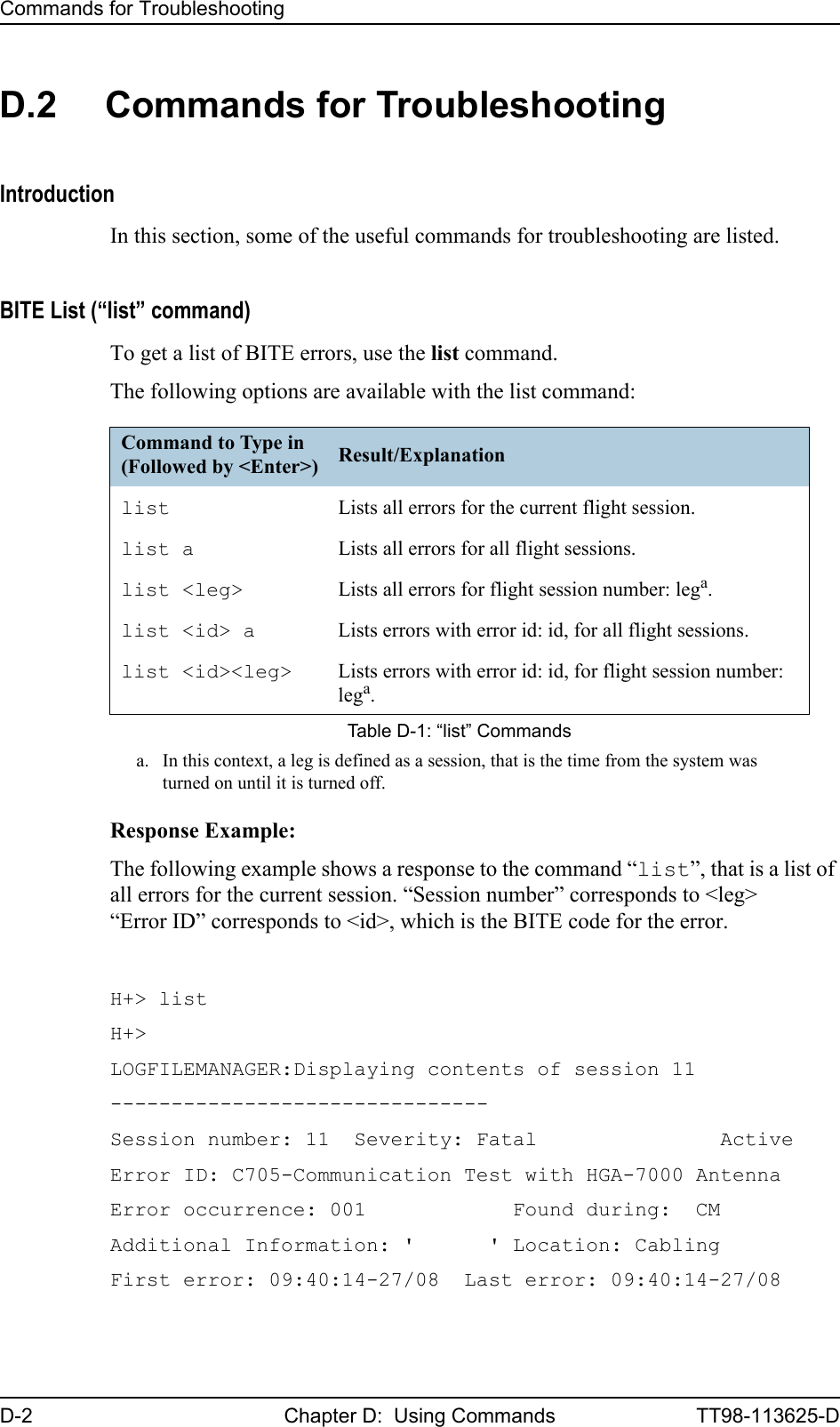
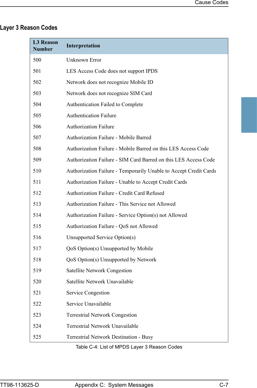
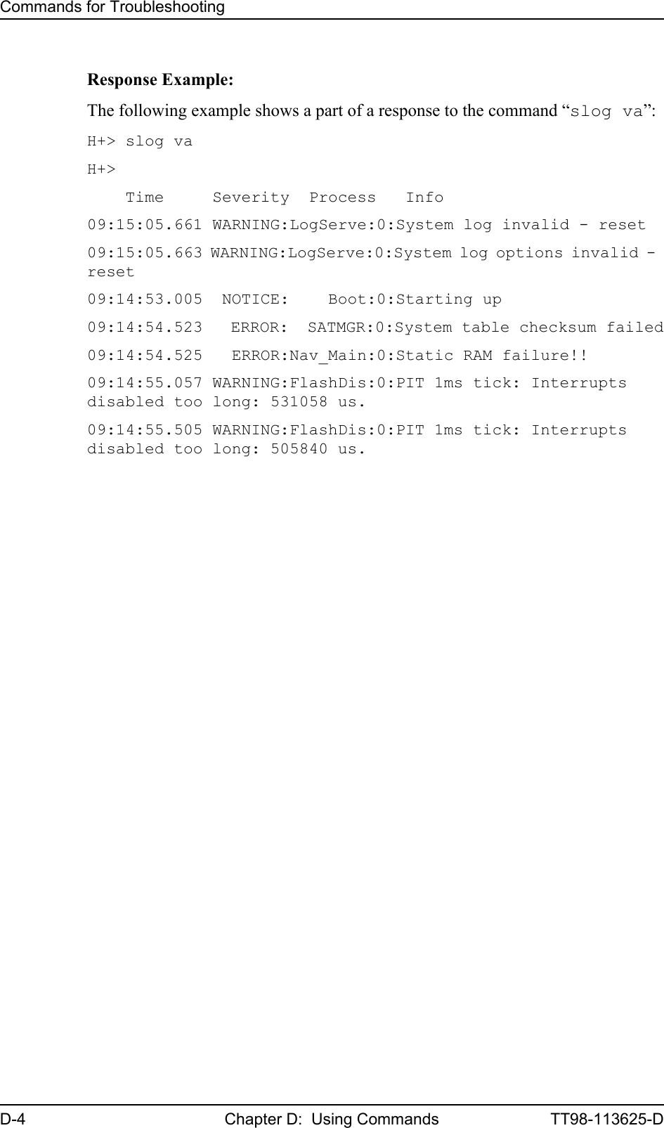
![Commands for TroubleshootingTT98-113625-D Chapter D: Using Commands D-3DDDDSystem Log (“slog” command)To access the system log, use the slog command. The following options are available with the slog command:Command to Type in (Followed by <Enter>) Result/Explanationslog l<prio> ... Inserts text into the system log with priority <prio>a. a. <prio>: Priority limit (one of {facewnid} or 0-7).The priority parameters {facewnid} are defined as:f: System is unusable.a: Action must be taken immediately.c: Critical conditions.e: Error conditions.w: Warning conditions.n: Normal but significant condition.i: Informational.d: Debug-level messages.slog t Shows the priority thresholds.slog tp <prio> Sets the print threshold. Log entries with priority <prio>a or higher will be printed.slog ts <prio> Sets the store threshold. Log entries with priority <prio>a or higher will be stored.slog v[arl] [-p<prio>] [-t<text>] [<count>] Shows the system log as defined by the parameters.Explanation of parameters:a : All entriesr : Reverse orderl : Long time format (toggles between long/short time format) (stickyb)<prio> : a (See table footnote)<text> : Only entries containing <text><count>: Max. number of entries shown (stickyb)b. “Sticky” means this setting is maintained during future command sessions until the setting is changed by the user.slog R Reset system log.Table D-2: “slog” Commands](https://usermanual.wiki/Thrane-and-Thrane-A-S/AERO-HSU/User-Guide-507698-Page-255.png)
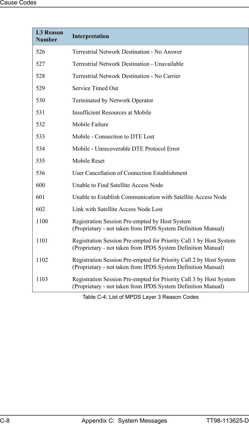
![TT98-113625-D F-1Appendix FFFFFReferences FF.1 Applicable Standards[1] IEEE Standard for Information technology - Telecommunications and information exchange between systems - Local and metropolitan area networks - Specific requirements Part 3: Carrier sense multiple access with collision detection (CSMA/CD) access method and physical layer specifications. IEEE Std 802.3, 2000 Edition (Incorporating IEEE Std 802.3, 1998 Edition, IEEE Std 802.3ac-1998, IEEE Std 802.3ab-1999, and IEEE Std 802.3ad-2000) [Adopted by ISO/IEC and re-designated as ISO/IEC 8802-3:2000(E)].[2] ISO/IEC 8877:1992 Information technology -- Telecommunications and information exchange between systems -- Interface connector and contact assignments for ISDN Basic Access Interface located at reference points S and T[3] RTCA/DO-160C and RTCA/DO-160DEnvironmental Conditions and Test Procedures for Airborne EquipmentRTCA Inc. July 29, 1997, incl. Change No. 1 (Dec. 14, 2000) and Change No. 2 (June 12, 2001).[4] Integrated Services Digital Network (ISDN)Basic User-Network Interface (UNI)ETSI EN 300 012-1 V1.2.2 (ITU I.430))[5] Integrated Services Digital Network (ISDN)ISDN User Network InterfacesITU-T Recommendation I.420[6] ARINC 429Mark 33 Digital Information Transfer Systems (DITS)[7] ARINC 404AAir Transport Equipment Cases and Racking.[8] ARINC 404B-1Connectors, Electrical, Rack and Panel, Rectangular, Rear Release Crimp Contacts.](https://usermanual.wiki/Thrane-and-Thrane-A-S/AERO-HSU/User-Guide-507698-Page-261.png)
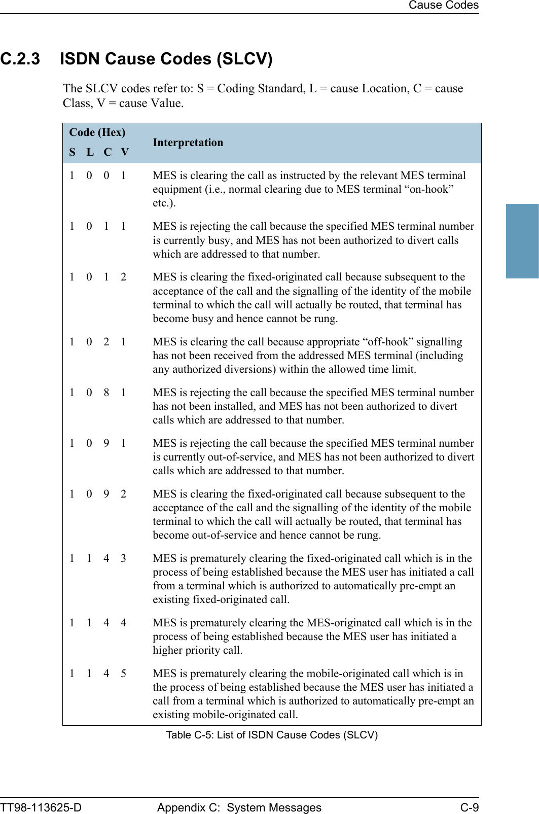
![Other ReferencesF-2 Appendix F: References TT98-113625-D[9] ARINC 702A-1Advanced Flight Management Computer SystemARINC, January 31, 2000[10] ARINC 741 P1-10Aviation Satellite Communication SystemPart 1, Aircraft Installation Provisions[11] ARINC 741 P2-7Aviation Satellite Communication SystemPart 2, System Design and Equipment Functional Description[12] RFC 1549: PPP in HDLC Framing. December 1993. (Obsoleted by RFC 1662)[13] CCITT Rec. G.473Standard US DTMF Telephone.[14] EIA/TIA-232-E: Interface Between Data Terminal Equipment and Data Circuit-Terminating Equipment Employing Serial Binary Data Interchange (superseded by TIA-232-F) Published: January 1, 1900. Category: Telecommunications.[15] RTCA DO-160C and DEnvironmental Conditions and Test Procedures for Airborne EquipmentF.2 Other References[16] Aero-HSD+ User Manual, Part number TT-98-119959](https://usermanual.wiki/Thrane-and-Thrane-A-S/AERO-HSU/User-Guide-507698-Page-262.png)