Thrane and Thrane A S AERO-HSU Aeronautical Satellite Telephone User Manual 98 113625 d
Thrane & Thrane A/S Aeronautical Satellite Telephone 98 113625 d
users manual
Thrane & Thrane A/S
Aero-HSD+
Installation and Maintenance Manual
Document number: TT98-113625-D
Release date: September 3, 2004

ii TT98-113625-D
Information in this document is subject to change without notice and does not represent a
commitment on the part of Thrane & Thrane A/S.
Copyright
© 2004 Thrane & Thrane A/S. All rights reserved. Printed in Denmark.
Trademark Acknowledgements
Windows is a registered trademark of Microsoft Corporation in the United States and other
countries.
MagnaStar is a registered trademark of Raytheon Company.
Inmarsat is a registered trademark of the International Maritime Satellite Organization
(IMSO) and is licensed by IMSO to Inmarsat Limited and Inmarsat Ventures plc.
Other product and company names mentioned in this manual may be trademarks or trade
names of their respective owners.
Company Addresses
Denmark USA
Thrane & Thrane A/S
Lundtoftegårdsvej 93 D
DK-2800 Lyngby
Denmark
Tel.: +45 39 55 88 00
Fax: +45 39 55 88 88
www.tt.dk
Thrane & Thrane, Inc.
509 Viking Drive, Suites K, L and M
Virginia Beach, VA 23452
USA
Tel.: +1 757 463-9557
Fax: +1 757 463-9581
www.tt.dk/us

TT98-113625-D iii
Record of Revisions
Rev. Description Release Date Initials
A Original document 23 May 2003 RP
B Change of naming:
TT-5000H changed to Aero-HSD+ and
Configuration Data Module changed to
Configuration Module
30 September 2003 HOC
C Ethernet connector pin naming, SDU and HPA
Power supply requirements, RF Cables requirements
and editorial changes.
17 December 2003 RP
D Chapters rearranged + new layout.
Introduction chapter:
Added list of external units to which the
Aero-HSD+ system can interface.
Equipment Drawings chapter:
HSU outline drawing, HSU tray drawing and
HSU tray connector drawing added.
Connectors and Pin-out:
Changed HPA connector drawing (key holes).
Changed pin-out for SDU rear receptacle.
Added pin-out for HSU.
Added “Mating connectors in aircraft”.
Installation chapter:
Added sections with Mounting Considerations
and Cable requirements.
Added section with recommended cables.
ARINC 429 interfaces wiring drawing has been
split into three: AHRS/IRS, ACARS/CMU and
CPDF.
MCDU/FMS wiring drawing added.
Wiring of MPDS, ISDN and Ethernet corrected.
MagnaStar wiring corrected + added #3 interface
as alternative.
WH-10 wiring drawing corrected (only three
handsets connected).
CC

iv TT98-113625-D
D
(continued)
Installation chapter (continued):
Sigma7 and 2.4GHz Cordless wiring added.
Dual Side Panel wiring added.
HSU wiring added.
ARINC 429 data format added
Commissioning section added.
Configuration chapter enhanced.
Check Procedures chapter added.
Service and maintenance chapter added
Equipment Specifications:
Max temperature for HPA and DLNA changed to
70 ºC.
Specs for Rx Splitter and Tx Coupler added.
Dimensions and Mounting added for all units.
System Messages appendix added.
Lists of Cause codes and BITE codes updated.
Cause codes for MPDS and ISDN added.
DO-160 forms corrected.
AT Profiles appendix added.
DO-160C/D Specifications appendix:
DO-160 forms added for handsets.
All DO-160 forms corrected.
“Using Commands” appendix added.
CC

TT98-113625-D v
Table of Contents
Chapter 1 About This Manual
1.1 Purpose ......................................................................................... 1-1
1.2 Organization .................................................................................. 1-1
1.3 Related Documentation .................................................................. 1-2
1.4 Precautions .................................................................................... 1-2
Chapter 2 Introduction to Aero-HSD+
2.1 General Description ....................................................................... 2-1
2.1.1 The Aero-HSD+ System ............................................................. 2-1
2.1.2 Standard Features ........................................................................ 2-3
2.2 Application ..................................................................................... 2-4
2.2.1 Minimum System ........................................................................ 2-4
2.2.2 Part Numbers .............................................................................. 2-5
2.2.3 Applicable External Units ........................................................... 2-8
2.3 System Block Diagrams ................................................................. 2-9
2.3.1 Overview ..................................................................................... 2-9
2.3.2 HGA-7000 High Gain Antenna .................................................. 2-9
2.3.3 ARINC 741 Compatible High Gain Antenna ........................... 2-10
2.3.4 Dual Side Panel Antenna System (Future Use) ........................ 2-11
2.3.5 User Interfaces .......................................................................... 2-12
2.3.6 MagnaStar® System .................................................................2-13
2.4 Operation Overview ..................................................................... 2-14
2.4.1 Configuration ............................................................................ 2-14
2.4.2 User Interface ............................................................................ 2-14
Chapter 3 Equipment Drawings
3.1 Introduction ................................................................................... 3-1
3.2 TT-5035A Satellite Data Unit ...........................................................3-2
3.2.1 TT-5035A-001 Configuration Module .......................................3-3
3.3 TT-5014A High Power Amplifier ...................................................... 3-4
3.4 TT-5012A Diplexer Low Noise Amplifier .........................................3-5

Table of Contents
vi TT98-113625-D
3.5 TT-5038A High Speed Data Unit (Optional) .....................................3-6
3.5.1 TT-5038A-002 Tx Coupler for Optional HSU ............................3-7
3.5.2 TT-5038A-003 Rx Power Splitter for Optional HSU .................3-8
3.6 TT-5620A 4-Wire Handset ...............................................................3-9
3.7 TT-5622A 4-Wire Cradle ................................................................3-10
3.8 TT-5621B 2-Wire Handset .............................................................3-11
3.9 TT-5622B 2-Wire Cradle ................................................................3-12
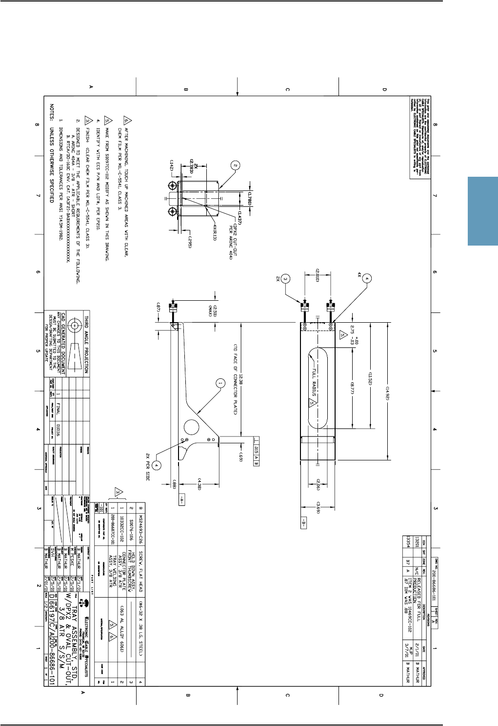
3.10 SDU and HPA Tray .......................................................................3-13
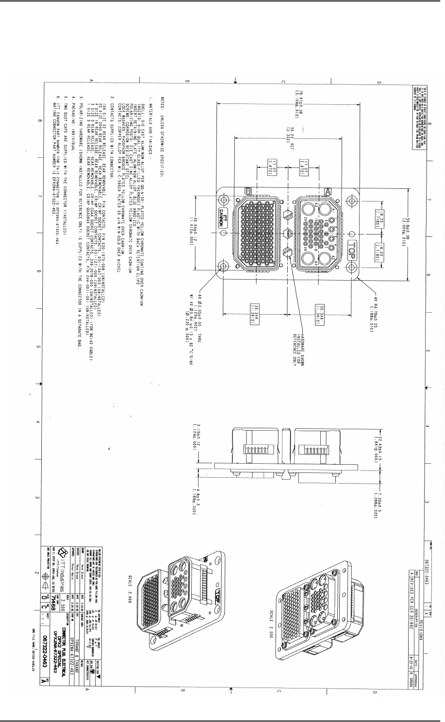
3.11 SDU Tray Connector .....................................................................3-14
3.12 HPA Tray Connector .....................................................................3-16
3.13 HSU Tray ......................................................................................3-17
3.14 HSU Tray Connector .....................................................................3-18
Chapter 4 Connectors and Pin-out
4.1 TT-5035A Satellite Data Unit ...........................................................4-1
4.1.1 Connectors on SDU .....................................................................4-1
4.1.2 SDU Front Connector ..................................................................4-2
4.1.3 SDU Rear Receptacle ..................................................................4-4
4.2 TT-5014A High Power Amplifier ....................................................4-11
4.2.1 HPA Rear Receptacle ................................................................4-11
4.3 TT-5038A HSU (Optional) ..............................................................4-13
4.3.1 Connectors on HSU ...................................................................4-13
4.3.2 HSU Front Connector ................................................................4-13
4.3.3 HSU Rear Receptacle ................................................................4-14
4.4 Cradle Connectors .......................................................................4-17
4.4.1 Connectors on 4-Wire Cradle ....................................................4-17
4.4.2 4-Wire Connector to SDU .........................................................4-18
4.4.3 Connectors on 2-Wire Cradle ....................................................4-20
4.4.4 2-Wire Connector to SDU .........................................................4-21
4.5 Mating Connectors in Aircraft .......................................................4-22

Table of Contents
TT98-113625-D vii
Chapter 5 Installation
5.1 General .......................................................................................... 5-1
5.1.1 Overview ..................................................................................... 5-1
5.1.2 Minimum System ........................................................................ 5-2
5.2 Mounting Considerations ...............................................................5-4
5.2.1 Overview ..................................................................................... 5-4
5.2.2 SDU ............................................................................................ 5-4
5.2.3 HSU ............................................................................................ 5-4
5.2.4 Rx Power Splitter ........................................................................ 5-5
5.2.5 HPA ............................................................................................ 5-5
5.2.6 DLNA ......................................................................................... 5-5
5.2.7 Antenna ....................................................................................... 5-6
5.3 Electrical Installation and Wiring .................................................... 5-7
5.3.1 Wiring Symbols ..........................................................................5-7
5.3.2 Wiring Power Supply .................................................................. 5-8
5.3.3 Wiring Antenna Systems .......................................................... 5-14
5.3.4 Wiring ARINC 429 Interfaces .................................................. 5-24
5.3.5 Wiring ICAO Address .............................................................. 5-29
5.3.6 Wiring MPDS RS-422, MPDS Ethernet and ISDN .................5-32
5.3.7 Wiring Telephone Systems ....................................................... 5-36
5.3.8 Wiring Thrane & Thrane Handset Systems .............................. 5-39
5.3.9 Wiring MagnaStar Handsets .....................................................5-42
5.3.10 Wiring WH-10 Handsets .......................................................... 5-45
5.3.11 Wiring 2.4GHz Cordless (4-Wire) Phone ................................. 5-48
5.3.12 Discretes for MagnaStar/WH-10 Handset Systems .................. 5-51
5.3.13 Wiring Sigma7 (2-Wire) Handsets ............................................ 5-52
5.3.14 Wiring 2.4GHz Cordless (2-Wire) Phone ................................. 5-53
5.3.15 Wiring Discretes ....................................................................... 5-54
5.3.16 Cockpit Voice and SIM Card Reader (Future Use) ..................5-58
5.3.17 Wiring Maintenance Handset, PC and Reset ............................ 5-59
5.4 Electrical Installation and Wiring, HSU ......................................... 5-63
5.4.1 Introduction to HSU .................................................................. 5-63
5.4.2 Wiring HSU Power Supply .......................................................5-63
5.4.3 Wiring Antenna Systems With HSU Installed .........................5-65
5.4.4 Wiring HSU to MPDS RS-232 , MPDS Ethernet and ISDN ... 5-73
5.4.5 Wiring HSU to Discretes and Maintenance PC Interface ......... 5-78

Table of Contents
viii TT98-113625-D
5.5 Recommended Cables ..................................................................5-81
5.5.1 Introduction ...............................................................................5-81
5.5.2 Power Cables, Allowed Cable Lengths .....................................5-81
5.5.3 Recommended RF Cables .........................................................5-84
5.5.4 Recommended Cables for ARINC 429 .....................................5-84
5.5.5 Recommended Cables for MPDS Ethernet ...............................5-85
5.6 Commissioning ............................................................................5-86
5.6.1 Inmarsat Aeronautical Service & Solution Providers ...............5-86
5.6.2 Activation ..................................................................................5-87
5.7 Verifying the Installation ...............................................................5-88
Chapter 6 Configuring the System
6.1 HSD+ Configuration Program .........................................................6-1
6.1.1 Overview .....................................................................................6-1
6.1.2 Installation ...................................................................................6-2
6.1.3 Description of HSD+CP ..............................................................6-3
6.1.4 Menu Overview ...........................................................................6-5
6.1.5 Basic Configuration .....................................................................6-6
6.2 Configuration of 3rd Party Phone Systems .....................................6-8
6.2.1 MagnaStar ...................................................................................6-8
6.2.2 Sigma7 ................................................................................................................ 6-9
6.2.3 2.4GHz Cordless .......................................................................6-10
Chapter 7 Check procedures
7.1 Basic Check Flow ...........................................................................7-1
7.2 Pre-Installation Check ....................................................................7-2
7.3 Functional Test, on Ground ............................................................7-4
7.4 Interference Test ............................................................................7-5
7.5 Functional Test, Airborne ...............................................................7-6
Chapter 8 Maintenance and Troubleshooting
8.1 Continued Airworthiness ................................................................8-1
8.1.1 General ........................................................................................8-1
8.1.2 Instructions ..................................................................................8-1

Table of Contents
TT98-113625-D ix
8.2 Software Update ............................................................................ 8-4
8.3 Troubleshooting .............................................................................8-6
8.3.1 Status Signalling .........................................................................8-6
8.3.2 Initial Troubleshooting .............................................................8-11
8.4 Returning Units for Repair ...........................................................8-15
8.4.1 Return Material Authorization (RMA) ..................................... 8-15
Appendices
Appendix A Equipment Specifications
A.1 Introduction .................................................................................. A-1
A.1.1 Total Weight of the Aero-HSD+ System ................................... A-1
A.2 Aero-HSD+ System Components ................................................... A-2
A.2.1 TT-5035A Satellite Data Unit (SDU) ........................................ A-2
A.2.2 TT-5014A High Power Amplifier (HPA) .................................. A-3
A.2.3 TT-5012A Diplexer Low Noise Amplifier (DLNA) ................. A-4
A.2.4 TT-5038A High Speed Data Unit (HSU) .................................. A-5
A.2.5 TT-5038A-002 Tx Coupler for Optional HSU .......................... A-6
A.2.6 TT-5038A-003 Rx Power Splitter for Optional HSU ................ A-7
A.3 Aero-HSD+ Handsets and Cradles ................................................. A-8
A.3.1 TT-5620A 4-Wire Handset ........................................................ A-8
A.3.2 TT-5622A 4-Wire Cradle .......................................................... A-9
A.3.3 TT-5621B 2-Wire Handset ...................................................... A-10
A.3.4 TT-5622B 2-Wire Cradle ......................................................... A-11
Appendix B DO-160C/D Specifications
B.1 General ......................................................................................... B-1
B.1.1 Certifying Agency ...................................................................... B-1
B.1.2 Environmental Qualification Forms .......................................... B-1

Table of Contents
xTT98-113625-D
B.2 Aero-HSD+ System Components ...................................................B-2
B.2.1 Satellite Data Unit ......................................................................B-2
B.2.2 Configuration Module ................................................................B-4
B.2.3 High Power Amplifier ................................................................B-5
B.2.4 Diplexer and Low Noise Amplifier ............................................B-7
B.2.5 High Speed Data Unit (Optional) ...............................................B-9
B.2.6 Tx Coupler and Rx Power Splitter for Optional HSU .............B-10
B.3 Aero-HSD+ Handsets and Cradles ...............................................B-12
B.3.1 4-Wire Handset and 4-Wire Cradle ..........................................B-12
B.3.2 2-Wire Handset and 2-Wire Cradle ..........................................B-14
Appendix C System Messages
C.1 Types of Messages ........................................................................C-1
C.2 Cause Codes .................................................................................C-2
C.2.1 H+ Cause Codes .........................................................................C-2
C.2.2 MPDS Cause Codes ...................................................................C-5
C.2.3 ISDN Cause Codes (SLCV) .......................................................C-9
C.3 BITE Error Codes ........................................................................C-17
C.3.1 Definition of Severity Levels ...................................................C-17
C.3.2 List of BITE Codes ..................................................................C-18
Appendix D Using Commands
D.1 Getting Started ..............................................................................D-1
D.2 Commands for Troubleshooting ....................................................D-2
Appendix E AT Profiles
E.1 Frequently Used AT Commands .................................................... E-1
E.2 LES settings for AT-calls ............................................................... E-2
Appendix F References
F.1 Applicable Standards .................................................................... F-1
F.2 Other References .......................................................................... F-2
Glossary ........................................................................................................ Glossary-1
Index ............................................................................................................. Index-1

TT98-113625-D xi
List of Figures
Chapter 1 About This Manual
Chapter 2 Introduction to Aero-HSD+
Figure 2-1: System Configuration with Electronically Steered HGA ................................2-9
Figure 2-2: System Configuration with ARINC 741 Compatible HGA ..........................2-10
Figure 2-3: System Configuration with Dual Side Panel Antenna System (Future Use).2-11
Figure 2-4: System Configuration with Different User Interfaces ...................................2-12
Figure 2-5: System Configuration with MagnaStar System.............................................2-13
Chapter 3 Equipment Drawings
Figure 3-1: Outline Drawing: Satellite Data Unit...............................................................3-2
Figure 3-2: Outline Drawing: Configuration Module.........................................................3-3
Figure 3-3: Outline Drawing: High Power Amplifier ........................................................3-4
Figure 3-4: Outline Drawing: Diplexer and Low Noise Amplifier ....................................3-5
Figure 3-5: Outline Drawing: High Speed Data Unit .........................................................3-6
Figure 3-6: Outline Drawing: Tx Coupler for Optional HSU ............................................3-7
Figure 3-7: Outline Drawing: Rx Power Splitter for Optional HSU ..................................3-8
Figure 3-8: Outline Drawing: 4-Wire Handset...................................................................3-9
Figure 3-9: Outline Drawing: 4-Wire Cradle ...................................................................3-10
Figure 3-10: Outline Drawing: 2-Wire Handset.................................................................3-11
Figure 3-11: Outline Drawing: 2-Wire Cradle ...................................................................3-12
Figure 3-12: Outline Drawing: Tray for SDU and HPA. ...................................................3-13
Figure 3-13: SDU Tray Connector: ITT Cannon DPX2NA-67322-463 ............................3-14
Figure 3-14: Contact Assembly: Quadrax Pin size 5 special: ITT Cannon 244-0011-001 3-15
Figure 3-15: HPA Tray Connector .....................................................................................3-16
Figure 3-16: Outline Drawing: Tray for HSU ....................................................................3-17
Figure 3-17: HSU Tray Connector, page 1 of 2 .................................................................3-18
Figure 3-18: HSU Tray Connector, page 2 of 2 .................................................................3-19
Chapter 4 Connectors and Pin-out
Figure 4-1: SDU Front Connector, Face View of Engaging End. (DB15F) ......................4-2
Figure 4-2: SDU Rear Receptacle and Mating Plug in Tray, Engaging End .....................4-4
Figure 4-3: HPA Receptacle, Face View of Engaging End. Index Code is 08 ................4-11
Figure 4-4: HSU Front Connector. Face View of Engaging End.....................................4-13
Figure 4-5: HSU Rear Receptacle and Mating Plug in Tray, Engaging End. ..................4-14

List of Figures
xii TT98-113625-D
Figure 4-6: 4-Wire Cradle Connectors, End View of Cradle........................................... 4-17
Figure 4-7: 4-Wire Cradle Connectors, Side View of Cradle .......................................... 4-17
Figure 4-8: 4-Wire Cradle Connector (DB15M). View: Solder Side .............................. 4-18
Figure 4-9: 2-Wire Cradle Connectors, End View of Cradle........................................... 4-20
Figure 4-10: 2-Wire Cradle Connectors, Side View of Cradle .......................................... 4-20
Figure 4-11: 2-Wire Cradle Connector (DB9M). View: Solder Side ................................ 4-21
Chapter 5 Installation
Figure 5-1: Minimum System ............................................................................................ 5-3
Figure 5-2: Mounting the Rx Power Splitter...................................................................... 5-5
Figure 5-3: Wiring SDU Power Supply ............................................................................. 5-8
Figure 5-4: Wiring HPA Power Supply ........................................................................... 5-11
Figure 5-5: Wiring HGA-7000 Antenna and TT-5012A DLNA ..................................... 5-15
Figure 5-6: Wiring AMT-50 Subsystem .......................................................................... 5-18
Figure 5-7: Wiring ARINC 741 Dual Side Panel Antenna System ................................. 5-21
Figure 5-8: Wiring AHRS/IRS......................................................................................... 5-24
Figure 5-9: Wiring ACARS/CMU ................................................................................... 5-26
Figure 5-10: Wiring CPDF................................................................................................. 5-27
Figure 5-11: Wiring MCDU/FMS...................................................................................... 5-28
Figure 5-12: Wiring ICAO................................................................................................. 5-30
Figure 5-13: Example of Wiring the Fictional ICAO Address 01234567 ......................... 5-30
Figure 5-14: Wiring MPDS RS-422, MPDS Ethernet and ISDN...................................... 5-32
Figure 5-15: MPDS Ethernet RJ45 Connector and Cable Connection to SDU................. 5-34
Figure 5-16: ISDN RJ45 Connector................................................................................... 5-35
Figure 5-17: Handset Interfaces, Possible Combinations of Connected Devices.............. 5-38
Figure 5-18: Wiring T&T Handset Systems ...................................................................... 5-39
Figure 5-19: Wiring MagnaStar Interface.......................................................................... 5-42
Figure 5-20: Wiring WH-10 Handsets............................................................................... 5-45
Figure 5-21: Wiring 2.4GHz Cordless 4-Wire Handsets ................................................... 5-48
Figure 5-22: Wiring Sigma7 Handsets ............................................................................... 5-52
Figure 5-23: Wiring 2.4GHz Cordless Handsets ............................................................... 5-53
Figure 5-24: Wiring Discrete Annunciators and Weight-on-Wheels................................. 5-54
Figure 5-25: Wiring Cockpit Voice and SIM Card Reader ............................................... 5-58
Figure 5-26: Wiring Maintenance PC and Reset ............................................................... 5-59
Figure 5-27: TT 37-112940 Data Cable Compliant with Front Connector........................ 5-61

List of Figures
TT98-113625-D xiii
Figure 5-28: Wiring Maintenance Handset ........................................................................5-62
Figure 5-29: Wiring HSU Power........................................................................................5-63
Figure 5-30: Wiring HSU to HGA-7000 Antenna System.................................................5-65
Figure 5-31: Wiring HSU to AMT-50 Subsystem..............................................................5-69
Figure 5-32: Wiring HSU to MPDS RS-232, MPDS Ethernet and ISDN .........................5-73
Figure 5-33: Ethernet RxD Twinax Contact Pin-out Definition.........................................5-75
Figure 5-34: Ethernet TxD Twinax Contact Pin-out Definition.........................................5-75
Figure 5-35: Ethernet RJ45 Connector and Cable Connection to HSU. ............................5-76
Figure 5-36: ISDN RJ45 Connector ...................................................................................5-77
Figure 5-37: Wiring HSU to Discretes and RS-232 PC Maintenance Interfaces...............5-78
Chapter 6 Configuring the System
Figure 6-1: HSD+CP User Interface...................................................................................6-3
Chapter 7 Check procedures
Chapter 8 Maintenance and Troubleshooting
Figure 8-1: Initial Check of LEDs ....................................................................................8-12
Figure 8-2: Initial Check of MPDS, Fax, 4-Wire Handsets and ISDN ............................8-13
Figure 8-3: Initial Check of Fax .......................................................................................8-14
App. A Equipment Specifications
App. B DO-160C/D Specifications
App. C System Messages
App. D Using Commands
App. E AT Profiles
App. F References

List of Figures
xiv TT98-113625-D

TT98-113625-D xv
List of Tables
Chapter 1 About This Manual
Table 1-1: List of Related Documentation ........................................................................1-2
Chapter 2 Introduction to Aero-HSD+
Table 2-1: Model and Part Numbers for the Aero-HSD+ System (T&T Units) ...............2-5
Table 2-2: Model and Part Numbers for Antenna Systems...............................................2-6
Table 2-3: Part Numbers for Klixon Circuit Breakers ......................................................2-6
Table 2-4: Part Number for Basic Installation Kit from ECS ...........................................2-6
Table 2-5: Part Numbers for Trays and Connectors..........................................................2-7
Table 2-6: List of Applicable External Units ....................................................................2-8
Chapter 3 Equipment Drawings
Chapter 4 Connectors and Pin-out
Table 4-1: Pin-out for SDU Front Connector....................................................................4-3
Table 4-2: Pin-out for SDU Rear Receptacle (Top Plug)..................................................4-7
Table 4-3: Pin-out for SDU Rear Receptacle (Bottom Plug)..........................................4-10
Table 4-4: Pin-out for HPA Receptacle (Top Plug) ........................................................4-12
Table 4-5: Pin-out for HPA Receptacle (Bottom Plug)...................................................4-12
Table 4-6: Pin-out for HSU Front Connector..................................................................4-14
Table 4-7: Pin-out for HSU Rear Receptacle..................................................................4-16
Table 4-8: Pin-out for 15 Pin Sub-D Male Connector on “pigtail” in 4-Wire Cradle.....4-19
Table 4-9: Pin-out for 9 Pin Sub-D Male Connector on “pigtail” in 2-Wire Cradle.......4-21
Table 4-10: Mating Connectors in Aircraft for SDU ........................................................4-22
Table 4-11: Mating Connector in Aircraft for HPA..........................................................4-23
Table 4-12: Mating Connectors in Aircraft for HSU ........................................................4-23
Chapter 5 Installation
Table 5-1: Pins for SDU Power Supply ............................................................................5-9
Table 5-2: Requirements to SDU Power Cables .............................................................5-10
Table 5-3: Pins for HPA Power Supply ..........................................................................5-12
Table 5-4: Pin for Remote HPA Power on/off by SDU ..................................................5-12
Table 5-5: Requirements to HPA Power Cables .............................................................5-13
Table 5-6: SDU Pins for HGA-7000 Antenna ................................................................5-16
Table 5-7: HPA Pins for HGA-7000 Antenna ................................................................5-16

List of Tables
xvi TT98-113625-D
Table 5-8: Requirements to RF Cables, HGA-7000 Antenna ........................................ 5-17
Table 5-9: SDU Pins for AMT-50 Subsystem................................................................ 5-19
Table 5-10: HPA Pins for AMT-50 Subsystem................................................................ 5-19
Table 5-11: Requirements to RF Cables, AMT-50 Subsystem ........................................ 5-20
Table 5-12: HPA Pins for Dual Side Panel Antenna System ........................................... 5-22
Table 5-13: SDU Pins for Dual Side Panel Antenna System ........................................... 5-23
Table 5-14: Requirements to RF Cables, ARINC 741 Dual Side Panel Antenna System 5-23
Table 5-15: SDU Pins for IRS and AHARS..................................................................... 5-24
Table 5-16: ARINC Data Format for IRS......................................................................... 5-25
Table 5-17: ARINC Data Format for AHRS .................................................................... 5-26
Table 5-18: SDU Pins for CMU ....................................................................................... 5-27
Table 5-19: SDU Pins for MPDS RS-422 ........................................................................ 5-33
Table 5-20: SDU Pins for MPDS 10BaseT Ethernet........................................................ 5-34
Table 5-21: SDU Pins for ISDN ....................................................................................... 5-35
Table 5-22: SDU Pins for 4-Wire Interface...................................................................... 5-40
Table 5-23: SDU Pins for 2-Wire Interface...................................................................... 5-41
Table 5-24: SDU Pins for MagnaStar Interface................................................................ 5-43
Table 5-25: SDU Pins for WH-10 Interface ..................................................................... 5-46
Table 5-26: SDU Pins for 2.4GHz Cordless (WH-10) Interface ...................................... 5-49
Table 5-27: SDU Discretes for MagnaStar/WH-10 Systems ........................................... 5-51
Table 5-28: SDU Pins for Discrete Annunciators............................................................. 5-54
Table 5-29: SDU Pins for WOW ...................................................................................... 5-55
Table 5-30: SDU Pins for WOW ...................................................................................... 5-56
Table 5-31: Specification of Discrete Types. ................................................................... 5-57
Table 5-32: SDU Pins for RS-232 PC Interface ............................................................... 5-60
Table 5-33: SDU Pins for Maintenance Handset Interface .............................................. 5-62
Table 5-34: Requirements to HSU Power Cables............................................................. 5-64
Table 5-35: HSU Pins for HGA-7000 Antenna System ................................................... 5-66
Table 5-36: SDU Pins for HGA-7000 Antenna System ................................................... 5-66
Table 5-37: HPA Pins for HGA-7000 Antenna System ................................................... 5-67
Table 5-38: Requirements to RF Cables, HGA-7000 Antenna ........................................ 5-68
Table 5-39: HSU Pins for HGA-7000 Antenna System ................................................... 5-70
Table 5-40: SDU Pins for HGA-7000 Antenna System ................................................... 5-70
Table 5-41: HPA Pins for HGA-7000 Antenna System ................................................... 5-71
Table 5-42: Requirements to RF Cables, AMT-50 Subsystem ........................................ 5-72

List of Tables
TT98-113625-D xvii
Table 5-43: HSU Pins for MPDS RS-232.........................................................................5-74
Table 5-44: HSU Pins for MPDS 10BaseT Ethernet ........................................................5-75
Table 5-45: HSU Pins for ISDN........................................................................................5-77
Table 5-46: HSU Pins for Rear Maintenance Connector Interface, RS-232.....................5-79
Table 5-47: HSU Pins for Discrete Outputs......................................................................5-80
Table 5-48: Allowed Lengths for SDU Power Cables ......................................................5-81
Table 5-49: Allowed Lengths for HPA Power Cables ......................................................5-82
Table 5-50: Allowed Lengths for HPA Chassis Cable......................................................5-82
Table 5-51: Allowed Lengths for HSU Power Cables ......................................................5-83
Table 5-52: List of Recommended RF Cables ..................................................................5-84
Chapter 6 Configuring the System
Chapter 7 Check procedures
Table 7-1: Check Sheet: Installation Check Before Inserting LRUs. ...............................7-2
Table 7-2: Check Sheet: Functional Test, on Ground .......................................................7-4
Table 7-3: Check Sheet: Functional Test, Airborne..........................................................7-6
Chapter 8 Maintenance and Troubleshooting
App. A Equipment Specifications
Table A-1: General Specifications for SDU......................................................................A-2
Table A-2: General Specifications for HPA......................................................................A-3
Table A-3: General Specifications for DLNA .................................................................. A-4
Table A-4: General Specifications for HSU......................................................................A-5
Table A-5: General Specifications for Tx Coupler ...........................................................A-6
Table A-6: General Specifications for Rx Power Splitter.................................................A-7
Table A-7: General Specifications for 4-Wire Handset .................................................... A-8
Table A-8: General Specifications for 4-Wire Cradle.......................................................A-9
Table A-9: General Specifications for 2-Wire Handset .................................................. A-10
Table A-10: General Specifications for 2-Wire Cradle.....................................................A-11
App. B DO-160C/D Specifications
Table B-1: RTCA/DO-160D Change Numbers, SDU...................................................... B-2
Table B-2: Environmental Qualification Form for SDU .................................................. B-2
Table B-3: RTCA/DO-160D Change Numbers, HPA...................................................... B-5

List of Tables
xviii TT98-113625-D
Table B-4: Environmental Qualification Form for HPA...................................................B-5
Table B-5: RTCA/DO-160C Change Numbers, DLNA ...................................................B-7
Table B-6: Environmental Qualification Form for DLNA................................................B-7
Table B-7: RTCA/DO-160D Change Numbers, Tx Coupler and Rx Power Splitter......B-10
Table B-8: Environmental Qualification Form for Tx Coupler and Rx Power Splitter..B-10
Table B-9: RTCA/DO-160C Change Numbers, 4-wire Handset and Cradle..................B-12
Table B-10: Environmental Qualification Form for 4-Wire Handset and Cradle.............B-12
Table B-11: Environmental Qualification Form for 2-Wire Handset and Cradle.............B-14
App. C System Messages
Table C-1: List of H+ Logon Reject Cause Codes............................................................C-2
Table C-2: List of H+ Call Reject Cause Codes................................................................C-3
Table C-3: List of MPDS Layer 2 Reason Codes .............................................................C-5
Table C-4: List of MPDS Layer 3 Reason Codes .............................................................C-7
Table C-5: List of ISDN Cause Codes (SLCV) ................................................................C-9
Table C-6: Definition of severity levels for BITE Codes................................................C-17
Table C-7: List of BITE Codes........................................................................................C-18
App. D Using Commands
Table D-1: “list” Commands ............................................................................................ D-2
Table D-2: “slog” Commands........................................................................................... D-3
Table D-3: “call_log” Commands .................................................................................... D-5
Table D-4: “flight” Commands......................................................................................... D-6
App. E AT Profiles
App. F References

TT98-113625-D 1-1
Chapter 1
1111
About This Manual 1
1.1 Purpose
The purpose of this manual is to provide information for installation, maintenance
and troubleshooting of the Aero-HSD+ system.
Important! The information, drawings and wiring diagrams contained in this
manual are intended as a reference for engineering planning only.
The drawings and wiring diagrams contained herein do not
represent any specific Supplemental Type Certificate (STC). It is
the installer's responsibility to compose installation drawings
specific to the aircraft. This manual and the drawings and wiring
diagrams contained herein may not be used as a substitute for an
STC package.
1.2 Organization
The chapters of this Installation Manual provide the following information:
•Introduction
A short overview of the Aero-HSD+ system and services.
•Equipment Drawings
Outline drawings of the units, trays and connectors of the Aero-HSD+ system.
•Connectors
Drawings and pin-out for the connectors, and a description of the required
mating connectors.
•Installation
Wiring drawings and detailed installation and wiring requirements.
•Configuration
An introduction to the HSD+ Configuration Program and a short description of
how to configure the Aero-HSD+ system. Also a short description of how to
configure some of the 3rd party handsets.
•Check Procedures
An overview of the recommended check procedures and checklists.
•Maintenance and Troubleshooting
Descriptions of Airworthiness, software update, LEDs and BITE test. Also a
flow chart of how to perform initial troubleshooting.
•Appendices
Equipment specifications, DO-160C/D Forms, Lists of error messages.

Related Documentation
1-2 Chapter 1: About This Manual TT98-113625-D
1.3 Related Documentation
The following documentation is related to this manual:
1.4 Precautions
Warnings, Cautions and Notes
Text marked with “Warning”, “Caution”, “Note” or “Important” show the
following type of data:
•Warning: A Warning is an operation or maintenance procedure that, if not
obeyed, can cause injury or death, or jeopardize the flight safety on the aircraft.
•Caution: A Caution is an operation or maintenance procedure that, if not
obeyed, can cause damage to the equipment.
•Note: A Note gives information to help the reader.
•Important: A text marked Important gives information that is important to the
user, e.g. to make the system work properly. This text does not concern
damage on equipment, flight safety nor personal safety.
General precautions
All personnel who operate equipment or do maintenance as specified in this
manual must know and follow the safety precautions.
The warnings and cautions that follow apply to all parts of this manual.
WARNING! Before using any material, refer to the manufacturers’ material
safety data sheets for safety information. Some materials can be
dangerous.
CAUTION! Do not use materials that are not equivalent to materials specified
by Thrane & Thrane. Materials that are not equivalent can cause
damage to the equipment.
CAUTION! The Aero-HSD+ system contains items that are electrostatic
discharge sensitive. Use approved industry precautions to keep the
risk of damage to a minimum when you touch, remove or insert
parts or assemblies.
Part Number Description
TT-98-119959 Aero-HSD+ User Manual
TT-99-119960 Aero-HSD+ Quick Guide
Table 1-1: List of Related Documentation

TT98-113625-D 2-1
Chapter 2
2222
Introduction to Aero-HSD+
2
2.1 General Description
This Installation manual describes the administrative and technical aspects,
features, functions and components of the Aero-HSD+ system.
All comments or recommendations regarding the installation, acceptance or
operation of the Aero-HSD+ system or its accessories and components should be
directed to Thrane & Thrane.
2.1.1 The Aero-HSD+ System
Important!
The design of the system is not intended to support the requirements of safety and
regularity of flight communications, in particular for Air Traffic Services (ATS)
or Aeronautical Operational Control (AOC) during the flight time.
The software used to control the unit operation complies with
RTCA specification DO-178B level E software.
Non-Safety Interfaces
The following interfaces in the Aero-HSD+ system are strictly for non-safety
usage:
• Cockpit voice (future use)
• ACARS/CMU
• CPDF (future use)
• MCDU/FMS (future use)

General Description
2-2 Chapter 2: Introduction to Aero-HSD+TT98-113625-D
Services
Housed in one system, the Aero-HSD+ combines the global voice, fax and PC
modem data capabilities of the Inmarsat® Aero-H+ service with the new Inmarsat
Swift64 aeronautical High Speed Data service.
• The Aero-H+ part provides three channels for global voice, fax, PC modem
data and cockpit communication.
• The Swift64 part provides a fourth channel, dedicated to high-speed data
requirements. The Swift64 channel may operate either using the Integrated
Services Digital Network (ISDN @ 64 kbit/s) or the IP-based Mobile Packet
Data Service (MPDS up to 64 kbit/s).
The Swift64 channel may also be used for speech or for 3.1 kHz audio e.g. for
fax.
PBX
The built-in PBX Unit connects up to four 4-wire handsets and two direct 2-wire
POTS interfaces for faxes, PC modems, auxiliary phones, headset interface boxes
etc.
Configuration Module
The Configuration Module (CM) contains all system and user settings for easy
replacement of the Satellite Data Unit (SDU). Access to these settings are
provided with the HSD+ Configuration Program (HSD+CP). For further
information on the HSD+CP, see HSD+ Configuration Program on page 6-1.
Different layers of write protection protect the CM contents; this includes
hardware protection of installation settings and optional pin code protection of
user data.
The Configuration Module is designed as a “plug-in” module for the SDU,
making it easier to replace the SDU while retaining all system and user settings.
Antenna Systems
The Aero-HSD+ may be acquired with an electronically steered High Gain
Antenna, HGA-7000, which is designed for fuselage mounting. The Aero-HSD+
system has built-in antenna control (ACU/BSU) for the HGA-7000 antenna.
Alternatively, an ARINC 741 antenna, such as the AMT-50 antenna for tail
mounting, may be used.

General Description
TT98-113625-D Chapter 2: Introduction to Aero-HSD+2-3
2222
2.1.2 Standard Features
Unique multi-channel solution, integrating the Inmarsat Aero-H+ and Swift64
services
A total of four channels (optionally five):
• two global H+ channels for voice, G3 fax or PC modem data
• one global H+ packet data channel for cockpit communications
• one spot beam High Speed Data (HSD) channel for ISDN or MPDS
As an option, one additional HSD channel can be installed, providing a total
data rate of 128 kbit/s.
Extremely small, compact and lightweight
ISDN for large file transmissions, video conferences, G4 fax etc.
Pay only “by the bit” with MPDS – ideally suited for Internet, e-mails etc.
Connect MPDS to airborne LAN via Ethernet or RS-422
3.1 kHz audio (14.4 kbit/s) for modems, G3 fax, high quality voice etc. via
HSD channel
STE/STU for secure transmissions
Chelton HGA-7000 antenna compatibility
ARINC 741 antenna compatibility
Built-in PBX interfacing to four 4-wire and two 2-wire connections

Application
2-4 Chapter 2: Introduction to Aero-HSD+TT98-113625-D
2.2 Application
2.2.1 Minimum System
A minimum working system has at least:
• one TT-5035A SDU
• one TT-5035A-001 CM
• one TT-5014A HPA
• one handset and cradle, e.g. a TT-5620A 4-Wire Handset and a TT-5622A 4-
Wire Cradle
• one antenna system. As antenna system, use either the AMT-50 Antenna
Subsystem or the HGA-7000 Antenna with a TT-5012A DLNA.
The minimum wiring required for an Aero-HSD+ system is described in the
section Minimum System Drawing on page 5-3.

Application
TT98-113625-D Chapter 2: Introduction to Aero-HSD+2-5
2222
2.2.2 Part Numbers
Applicable Thrane & Thrane Model- and Part Numbers
This Installation Manual is for the Aero-HSD+ system and is applicable to the
model- and part numbers below:
T&T Part Number Model Number Description
405035A TT-5035A Satellite Data Unit (SDU) [without CM]
405035A-001 TT-5035A-001 Configuration Module (CM)
405038A TT-5038A High Speed data Unit (HSU). Additional
Swift64 channel for a total of 128 kbit/s
(optional)
405038A-002 TT-5038A-002 HSU Tx Coupler (optional)
405038A-003 TT-5038A-003 HSU Rx Power Splitter (optional)
405014A TT-5014A High Power Amplifier (HPA)
405012A-THR TT-5012A Diplexer / Low Noise Amplifier (DLNA)
405620A-THW TT-5620A 4-Wire Handset (white)
405620A-THR TT-5620A 4-Wire Handset (black)
405622A-THW TT-5622A 4-Wire Cradle (white)
405622A-THR TT-5622A 4-Wire Cradle (black)
405621B-THW TT-5621B 2-Wire Handset (white)
405621B-THR TT-5621B 2-Wire Handset (black)
405622B-THW TT-5622B 2-Wire Cradle (white)
405622B-THR TT-5622B 2-Wire Cradle (black)
TT 37-112940 Maintenance Cable
(SDU Front Connector Maintenance via PC)
TT 83-119958 CD with HSD+ Configuration Program
Table 2-1: Model and Part Numbers for the Aero-HSD+ System (T&T Units)

Application
2-6 Chapter 2: Introduction to Aero-HSD+TT98-113625-D
Applicable antenna systems
Circuit Breakers
Installation Kit
Complete installation kits including harness wiring can be obtained through ECS
(Electronic Cable Specialists, Inc.). The part number for a basic installation kit is
stated below. For further information, contact:
ECS, USA
Phone: +1 414.421.5300
Email: sales@ecsdirect.com
Homepage: www.ecsdirect.com
Part Number Model Number Description
677-A0106 HGA-7000 Chelton Electronically Steered High Gain Antenna
0881-A-0001 AMT-50 EMS Antenna Control Unit (ACU)
0476-A-00364 AMT-50 EMS Diplexer/LNA (DLNA)
0476-A-00377 AMT-50 EMS Antenna Frame Assembly (Antenna)
Table 2-2: Model and Part Numbers for Antenna Systems
Part Number Recommended Aircraft Circuit Breakers
4310-001-4 Klixon 2TC series, 4 A current rating (SDU)
4310-001-20 Klixon 2TC series, 20 A current rating (HPA)
Table 2-3: Part Numbers for Klixon Circuit Breakers
Part Number Installation Kit
120-94981-102 ECS Basic Installation Kit for Aero-HSD+
Table 2-4: Part Number for Basic Installation Kit from ECS
Application
TT98-113625-D Chapter 2: Introduction to Aero-HSD+2-7
2222
Trays and Connectors
Part Number Recommended Trays for Jet Aircraft
200-86686-101 ECS Tray Assembly 3/8-size ATR (for HPA and SDU)
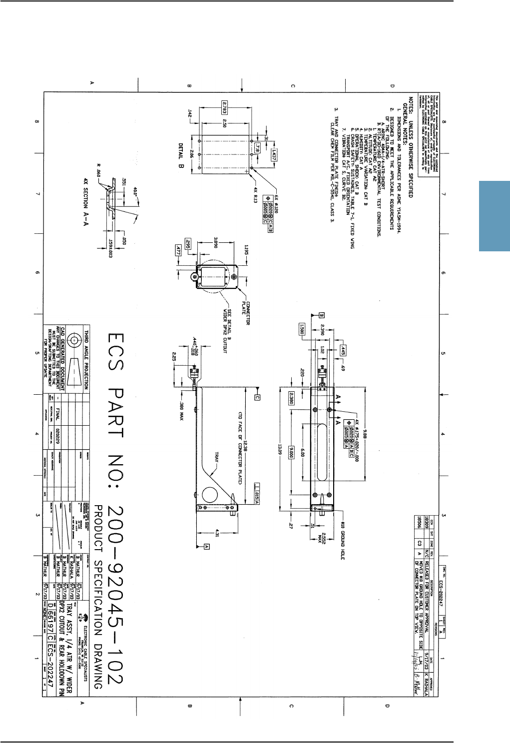
200-92045-102 ECS Tray Assembly 1/4-size ATR (for HSU)
Part Number Required Plug for SDU Tray
DPX2NA-67322-463 ITT Cannon Connector, Dual Plug
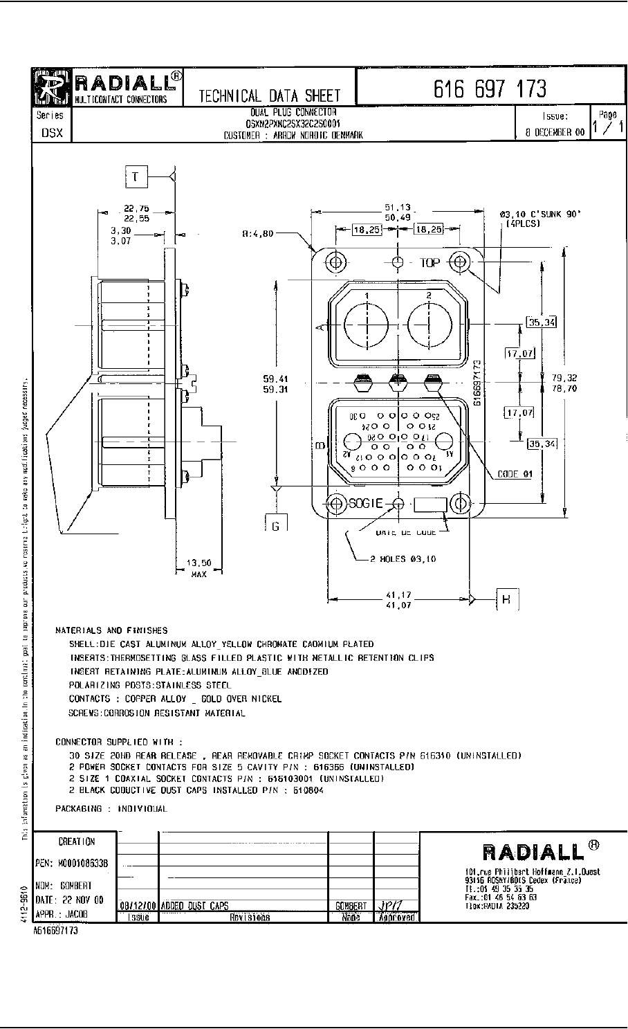
Part Number Recommended Plug for HPA Tray
616 697 173 RADIALL Dual Plug Connector
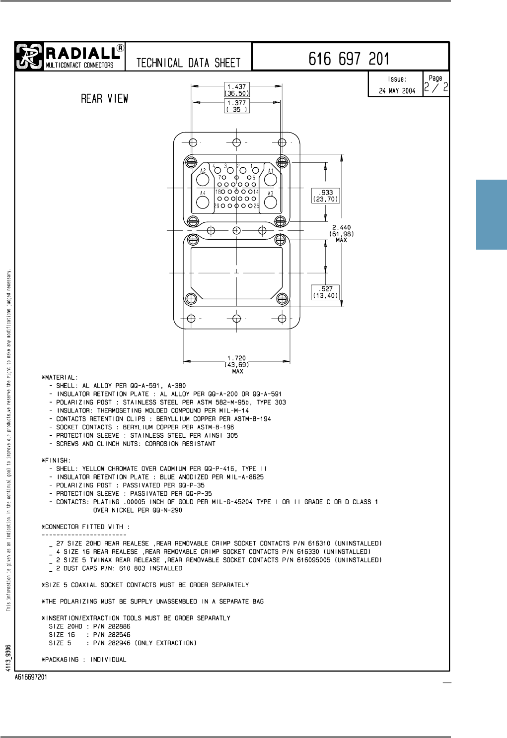
Part Number Required Plug for optional HSU Tray
DSXN2PS33C45X00500 ECS Dual Plug Connector
P924 Size #5 Twinax contact
Table 2-5: Part Numbers for Trays and Connectors

Application
2-8 Chapter 2: Introduction to Aero-HSD+TT98-113625-D
2.2.3 Applicable External Units
Apart from the antennas listed in the previous section, the Aero-HSD+ system has
been tested with various other external units. Below is a list of tested units.
Note that the Aero-HSD+ system may also be able to interface to other units not
mentioned below.
Product Name Product Description Manufacturer
2.4GHz Cordless Cordless handset
system
ICG, USA
Phone:
Email:
Homepage:
1-800-279-1991 or
(757)947-1030
sales@intcomgrp.com.
www.intcomgrp.com
Sigma7Handset system ICG (see contact info above)
AeroRouter 700 LAN router ICG (see contact info above)
JetLAN Cabin file server Pentar Avionics, USA
Phone:
Fax:
Email:
Homepage:
1-888-655-3755 or
(425)424-3370
425.424.3380
sales@pentar.com
www.pentar.com
AMAR
(Advanced
Mobile Access
Router)
LAN Router Lufthansa Technik AG, Germany
Homepage: www.lufthansa-technik.com
(The homepage lists regional sales office).
Table 2-6: List of Applicable External Units

System Block Diagrams
TT98-113625-D Chapter 2: Introduction to Aero-HSD+2-9
2222
2.3 System Block Diagrams
2.3.1 Overview
The following block diagrams show basic system component interconnection.
The first three diagrams show the wiring differences according to antenna choice
and antenna steering source.
The following system block diagrams show the user interface options and how the
system can be interfaced with MagnaStar system PBX communication.
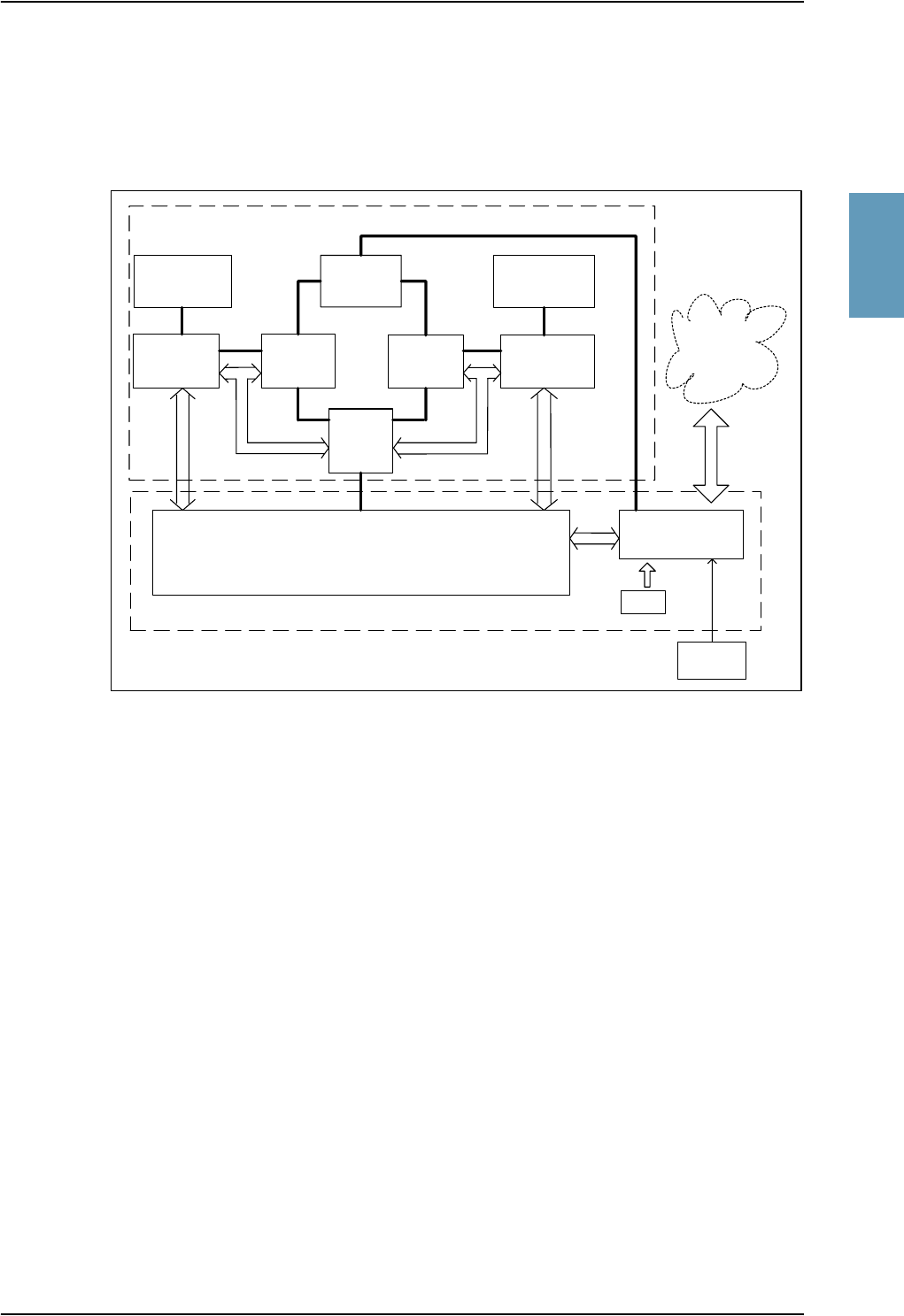
2.3.2 HGA-7000 High Gain Antenna
The Aero-HSD+ system has built-in antenna control (ACU/BSU) for the
electronically steered HGA-7000 antenna.
Figure 2-1: System Configuration with Electronically Steered HGA
Antenna
HPA
HGA-7000
DLNA
SDU
IRS /
AHRS
Aero-HSD
CM
+
User
Interfaces
TT-5012A
GPS
Tx
Rx

System Block Diagrams
2-10 Chapter 2: Introduction to Aero-HSD+TT98-113625-D
2.3.3 ARINC 741 Compatible High Gain Antenna
The Aero-HSD+ system also supports ARINC 741 compatible antenna systems,
such as the mechanically steered AMT-50 subsystem.
Figure 2-2: System Configuration with ARINC 741 Compatible HGA
Antenna
ACU/
BSU
HPA
ARINC741 Antenna Subsystem
ARINC741
DLNA
SDU
IRS
Aero-HSD
CM
+
User
Interfaces
TxRx
System Block Diagrams
TT98-113625-D Chapter 2: Introduction to Aero-HSD+2-11
2222
2.3.4 Dual Side Panel Antenna System (Future Use)
An ARINC 741 dual side panel antenna system may be installed, in order to
improve the view to the satellite.
Figure 2-3: System Configuration with Dual Side Panel Antenna System (Future Use)
HGA (Port)
HPA
DLNA 1
(Port)
SDU
IRS
Aero-HSD+ System
CM
User
Interfaces
HPR
DLNA 2
(STBO)
BSU
(Port)
BSU
(STBO)
HGA
(STBO)
Combiner
ARINC 741 Dual Side Panel Antenna System
Tx Rx
System Block Diagrams
2-12 Chapter 2: Introduction to Aero-HSD+TT98-113625-D
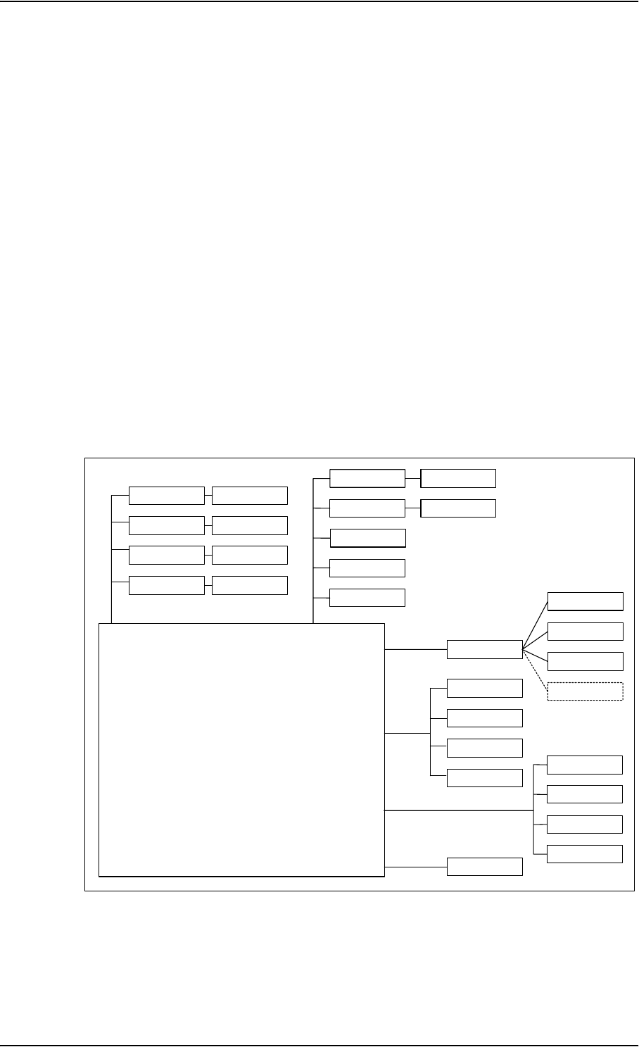
2.3.5 User Interfaces
The Aero-HSD+ system has the following user interfaces:
• Four 4-wire PBX interfaces, which can be used e.g. for the TT-5620A handset
and TT-5622A cradle.
The TT-5622A cradle has an RJ11 connector to which additional 2-wire
terminals can be connected, e.g. for fax or modem data.
• Two 2-wire POTS interfaces, which can be used for the TT-5621B handset and
TT-5622B cradle or other POTS handsets.
The TT-5622B cradle has an RJ11 connector to which additional 2-wire
terminals can be connected, e.g. for fax or modem data.
• MPDS via RS-422 or 10BaseT Ethernet interface.
• Euro ISDN S-bus interface for PC, Fax or STE
• ARINC 429 interfaces for e.g. CMU/ACARS or MCDU/FMS.
• Discrete outputs for annunciators.
The following drawing shows most of the possible user interfaces.
Figure 2-4: System Configuration with Different User Interfaces
4-W Cradle
TT-5035A SDU
2-W Cradle
G3 Fax
Laptop/PC
STU
G4 Fax
Laptop/PC
Video Ph.
STE
CMU
AFIS
ACARS
MCDU/FMS
PC #1
PC #2
PC #3
IP ROUTER
2-wire / RJ-11
ISDN
RS-422/
Ethernet
LAN
ARINC 429
2-W Cradle
4-wire
2-W Phone
2-W Phone
4-W Cradle 4-W Handset
4-W Handset
4-W Cradle 4-W Handset
4-W Cradle 4-W Handset
Annunciators
Discrete
Outputs

System Block Diagrams
TT98-113625-D Chapter 2: Introduction to Aero-HSD+2-13
2222
2.3.6 MagnaStar® System
The MagnaStar system is a terrestrial-based telephone system that can be
connected to the 4-wire interfaces of the Aero-HSD+ system.
The connections between the SDU and AIU1 and AIU2 are standard 4-wire
WH-10 Interfaces, with one additional discrete interface (Service Unavailable).
Note: The block diagram below is a simplified overview of one of the
MagnaStar systems. For information on the MagnaStar system, refer to
the relevant MagnaStar installation manual.
Figure 2-5: System Configuration with MagnaStar System
Magnastar System
SDU
Aero-HSD+ System
AIU
AIU
CDBR-2
ARTU/TMU
Handset
Handset
4-Wire
4-Wire
Satcom Service
Unavailable

Operation Overview
2-14 Chapter 2: Introduction to Aero-HSD+TT98-113625-D
2.4 Operation Overview
Note: The Aero-HSD+ system should not be used during take-off and landing.
2.4.1 Configuration
The main configuration tool for the Aero-HSD+ system is the HSD+
Configuration Program (HSD+CP), which can be launched from a standard PC
connected to the front connector of the SDU.
For further information, see HSD+ Configuration Program on page 6-1.
2.4.2 User Interface
The Aero-HSD+ System uses the 4-wire handset as the main interface between the
operator and the system. The display and keypad of the handset give access to the
menu system.
Refer to the Aero-HSD+ User Manual for operating procedures. The Aero-HSD+
User Manual introduces and explains system capabilities and features, handset
controls and functions, placing and receiving calls, and use of the menu system.

TT98-113625-D 3-1
Chapter 3
3333
Equipment Drawings 3
3.1 Introduction
The following pages show copies of mechanical drawings of important system
units relevant for an installation.
IMPORTANT NOTE
The drawings in this manual are for reference only. Contact Thrane & Thrane to
obtain the latest version of the outline drawings.
TT-5035A Satellite Data Unit
3-2 Chapter 3: Equipment Drawings TT98-113625-D
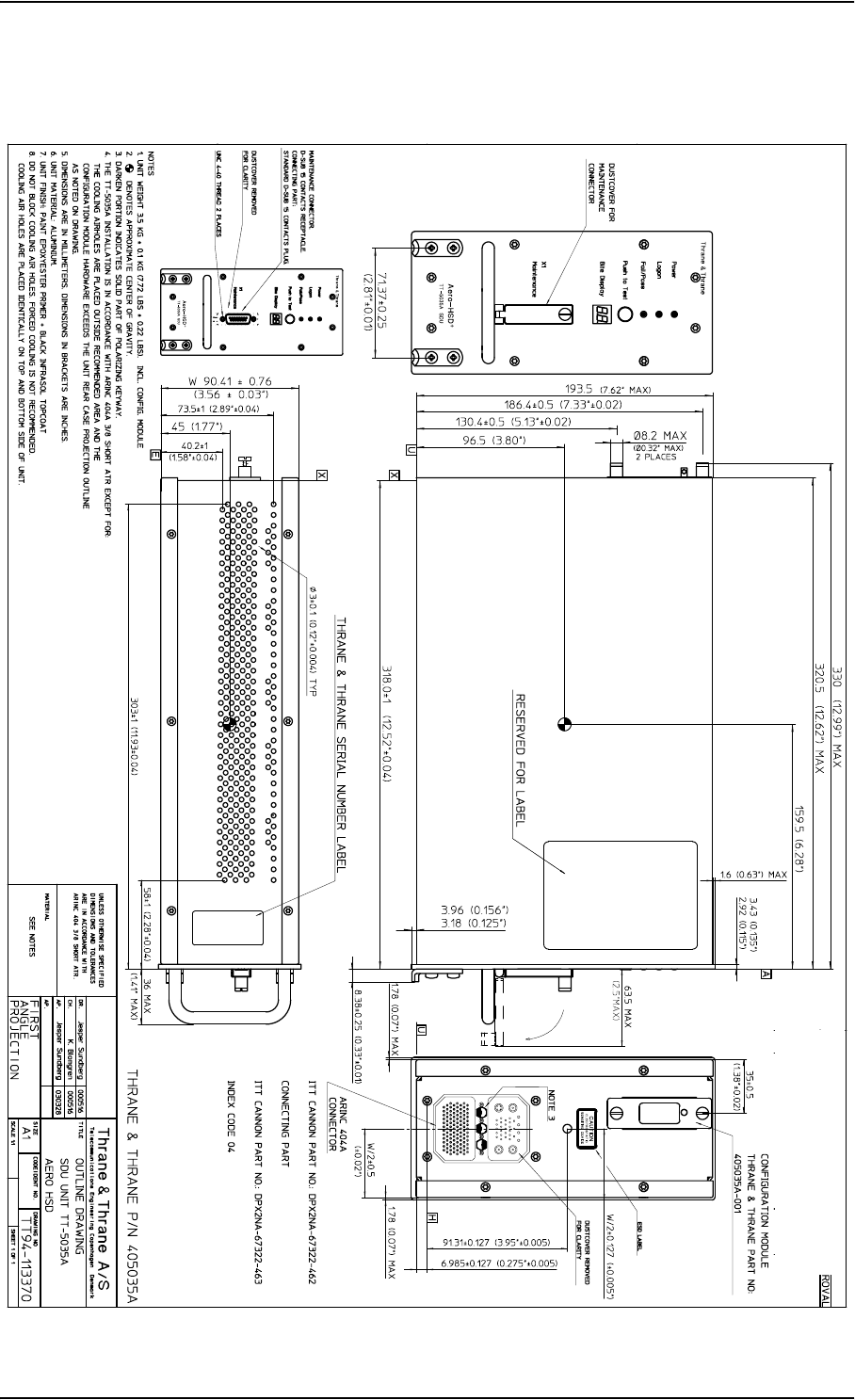
3.2 TT-5035A Satellite Data Unit
Figure 3-1: Outline Drawing: Satellite Data Unit
TT-5035A Satellite Data Unit
TT98-113625-D Chapter 3: Equipment Drawings 3-3
3333
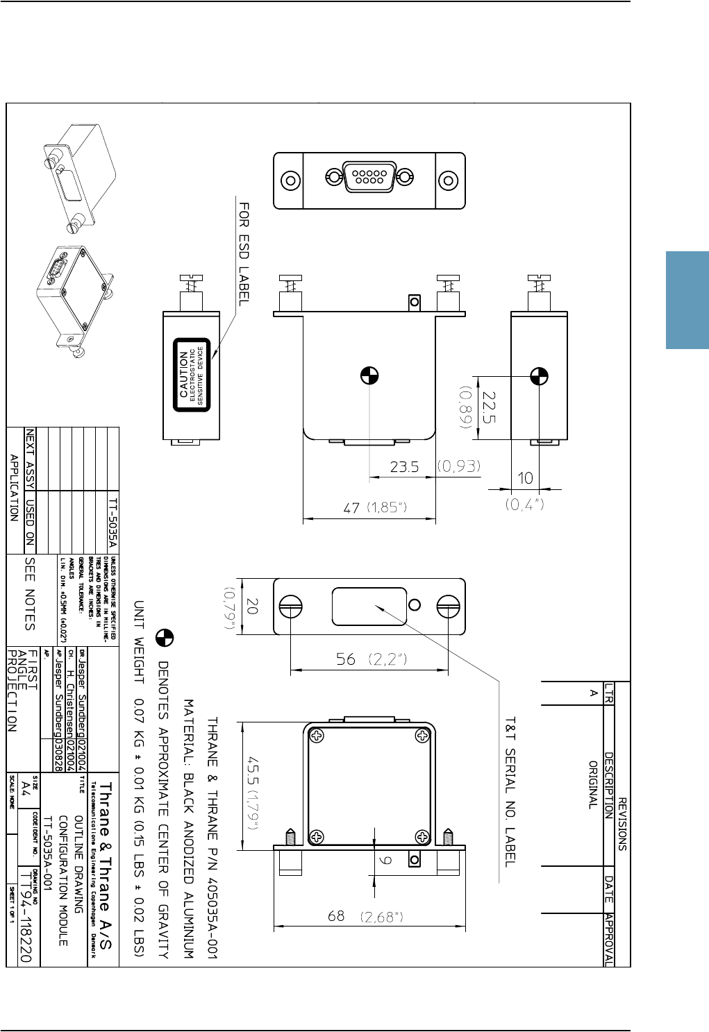
3.2.1 TT-5035A-001 Configuration Module
Figure 3-2: Outline Drawing: Configuration Module
TT-5014A High Power Amplifier
3-4 Chapter 3: Equipment Drawings TT98-113625-D
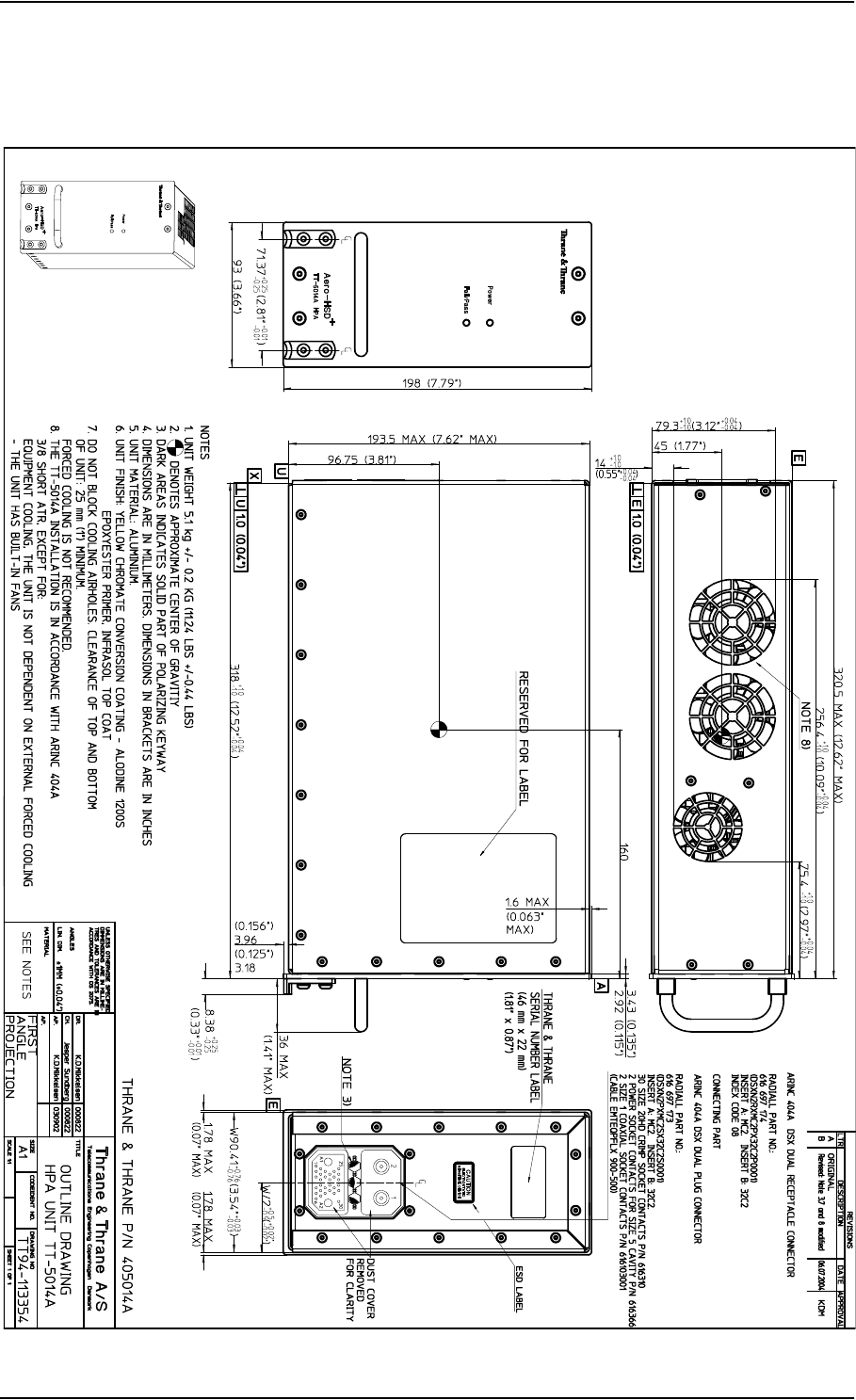
3.3 TT-5014A High Power Amplifier
Figure 3-3: Outline Drawing: High Power Amplifier
TT-5012A Diplexer Low Noise Amplifier
TT98-113625-D Chapter 3: Equipment Drawings 3-5
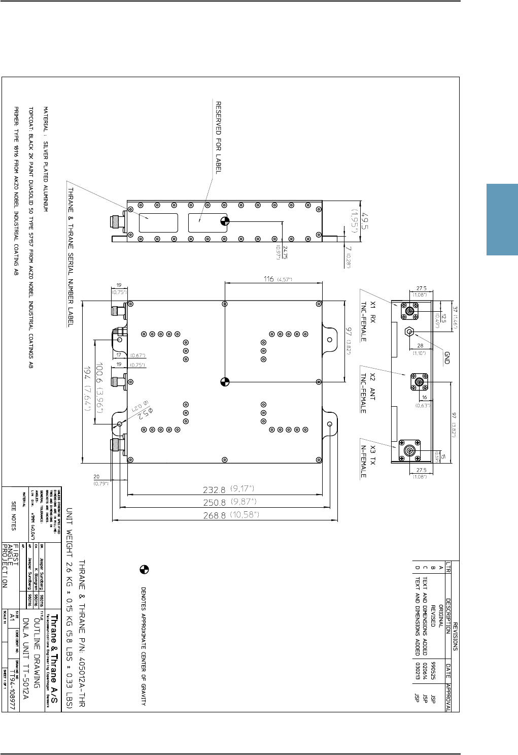
3333
3.4 TT-5012A Diplexer Low Noise Amplifier
Figure 3-4: Outline Drawing: Diplexer and Low Noise Amplifier

TT-5038A High Speed Data Unit (Optional)
3-6 Chapter 3: Equipment Drawings TT98-113625-D
3.5 TT-5038A High Speed Data Unit (Optional)
Figure 3-5: Outline Drawing: High Speed Data Unit
TT-5038A High Speed Data Unit (Optional)
TT98-113625-D Chapter 3: Equipment Drawings 3-7
3333
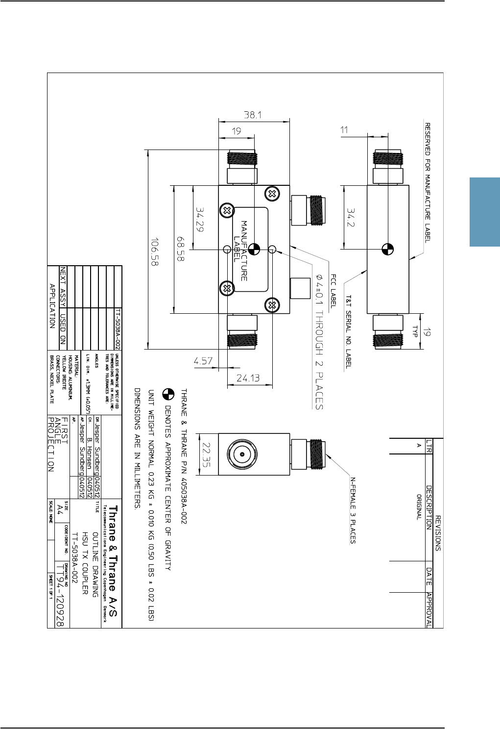
3.5.1 TT-5038A-002 Tx Coupler for Optional HSU
Figure 3-6: Outline Drawing: Tx Coupler for Optional HSU
TT-5038A High Speed Data Unit (Optional)
3-8 Chapter 3: Equipment Drawings TT98-113625-D
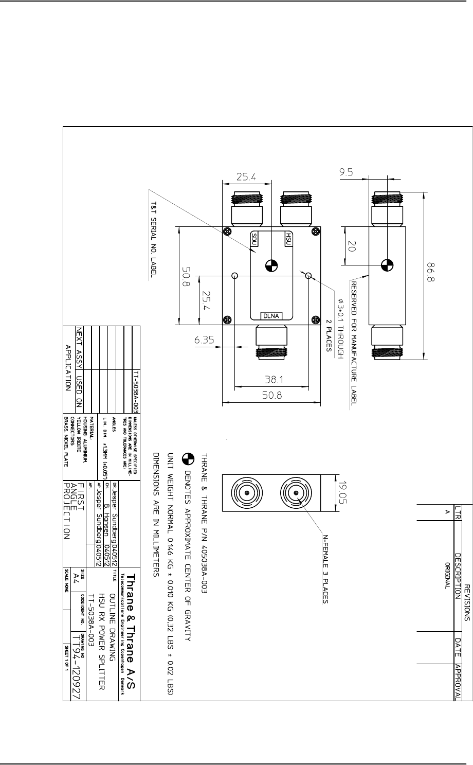
3.5.2 TT-5038A-003 Rx Power Splitter for Optional HSU
Note: If the Rx Power Splitter is to be mounted on a flat surface, mount it on a
3 mm mounting plate to provide enough space for mounting of the
connectors. For further information see Rx Power Splitter on page 5-5.
Figure 3-7: Outline Drawing: Rx Power Splitter for Optional HSU
TT-5620A 4-Wire Handset
TT98-113625-D Chapter 3: Equipment Drawings 3-9
3333
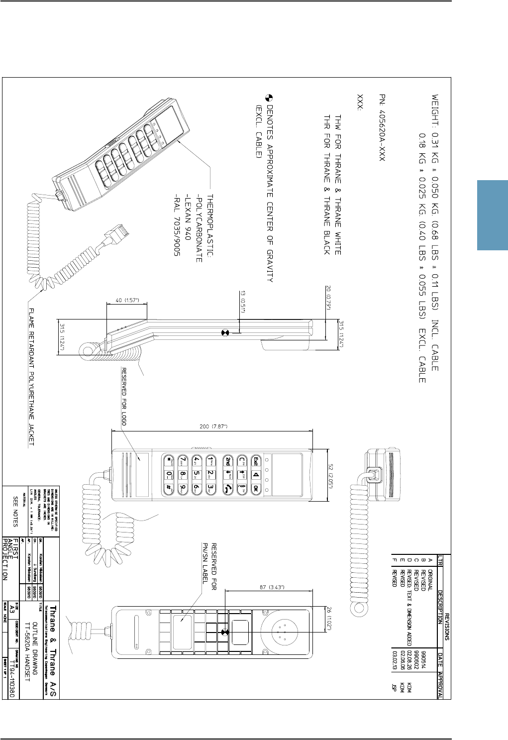
3.6 TT-5620A 4-Wire Handset
Figure 3-8: Outline Drawing: 4-Wire Handset

TT-5622A 4-Wire Cradle
3-10 Chapter 3: Equipment Drawings TT98-113625-D
3.7 TT-5622A 4-Wire Cradle
Figure 3-9: Outline Drawing: 4-Wire Cradle
TT-5621B 2-Wire Handset
TT98-113625-D Chapter 3: Equipment Drawings 3-11
3333
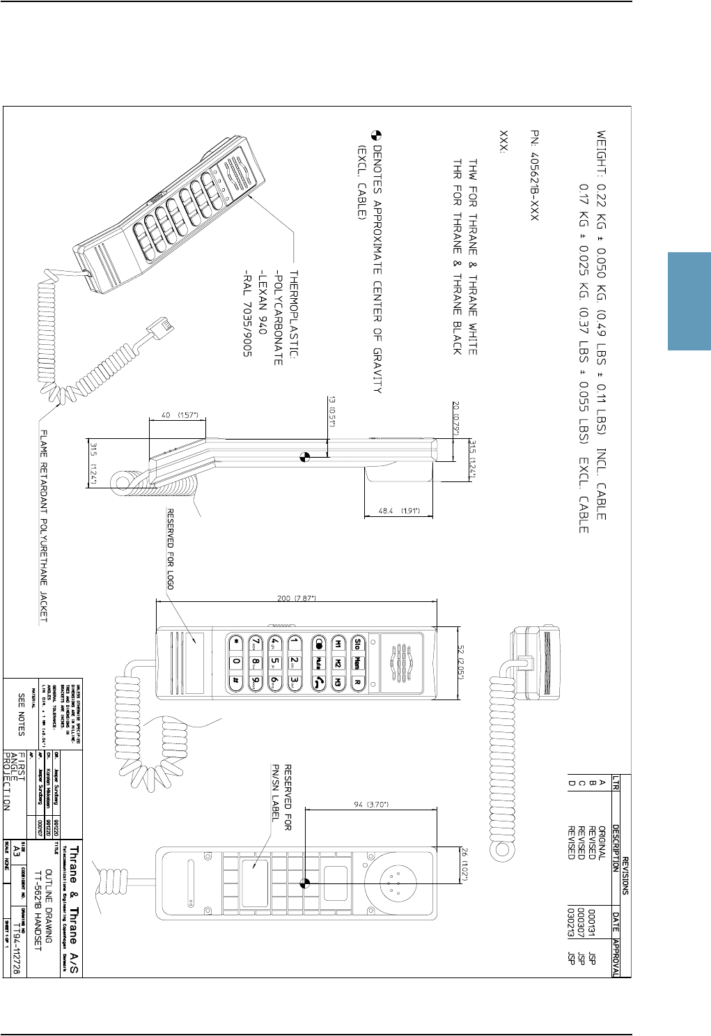
3.8 TT-5621B 2-Wire Handset
Figure 3-10: Outline Drawing: 2-Wire Handset
TT-5622B 2-Wire Cradle
3-12 Chapter 3: Equipment Drawings TT98-113625-D
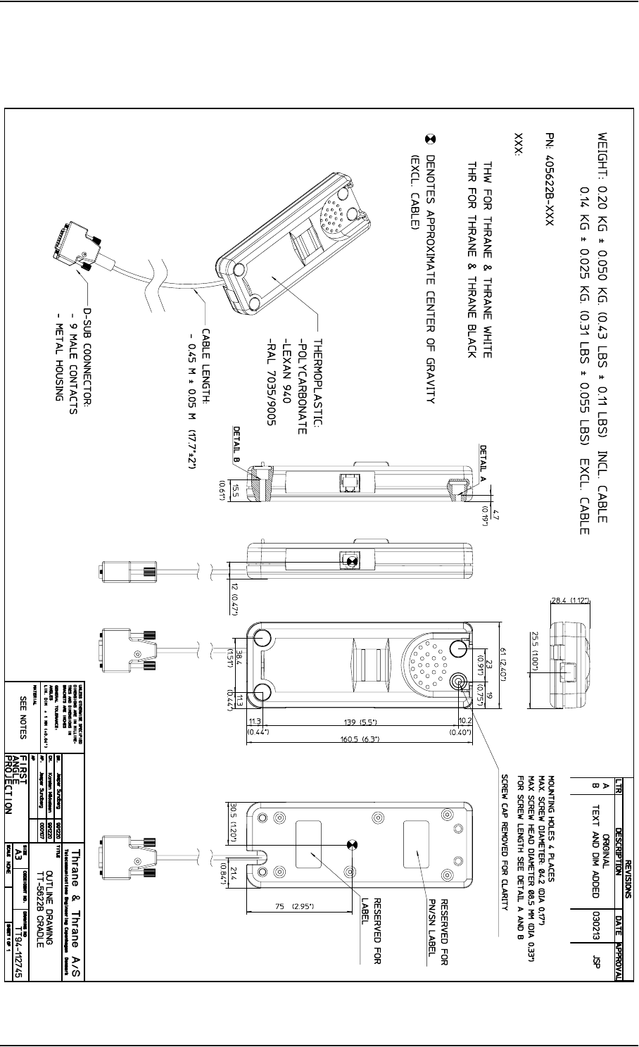
3.9 TT-5622B 2-Wire Cradle
Figure 3-11: Outline Drawing: 2-Wire Cradle
SDU and HPA Tray
TT98-113625-D Chapter 3: Equipment Drawings 3-13
3333
3.10 SDU and HPA Tray
Figure 3-12: Outline Drawing: Tray for SDU and HPA.
SDU Tray Connector
3-14 Chapter 3: Equipment Drawings TT98-113625-D
3.11 SDU Tray Connector
Figure 3-13: SDU Tray Connector: ITT Cannon DPX2NA-67322-463
SDU Tray Connector
TT98-113625-D Chapter 3: Equipment Drawings 3-15
3333
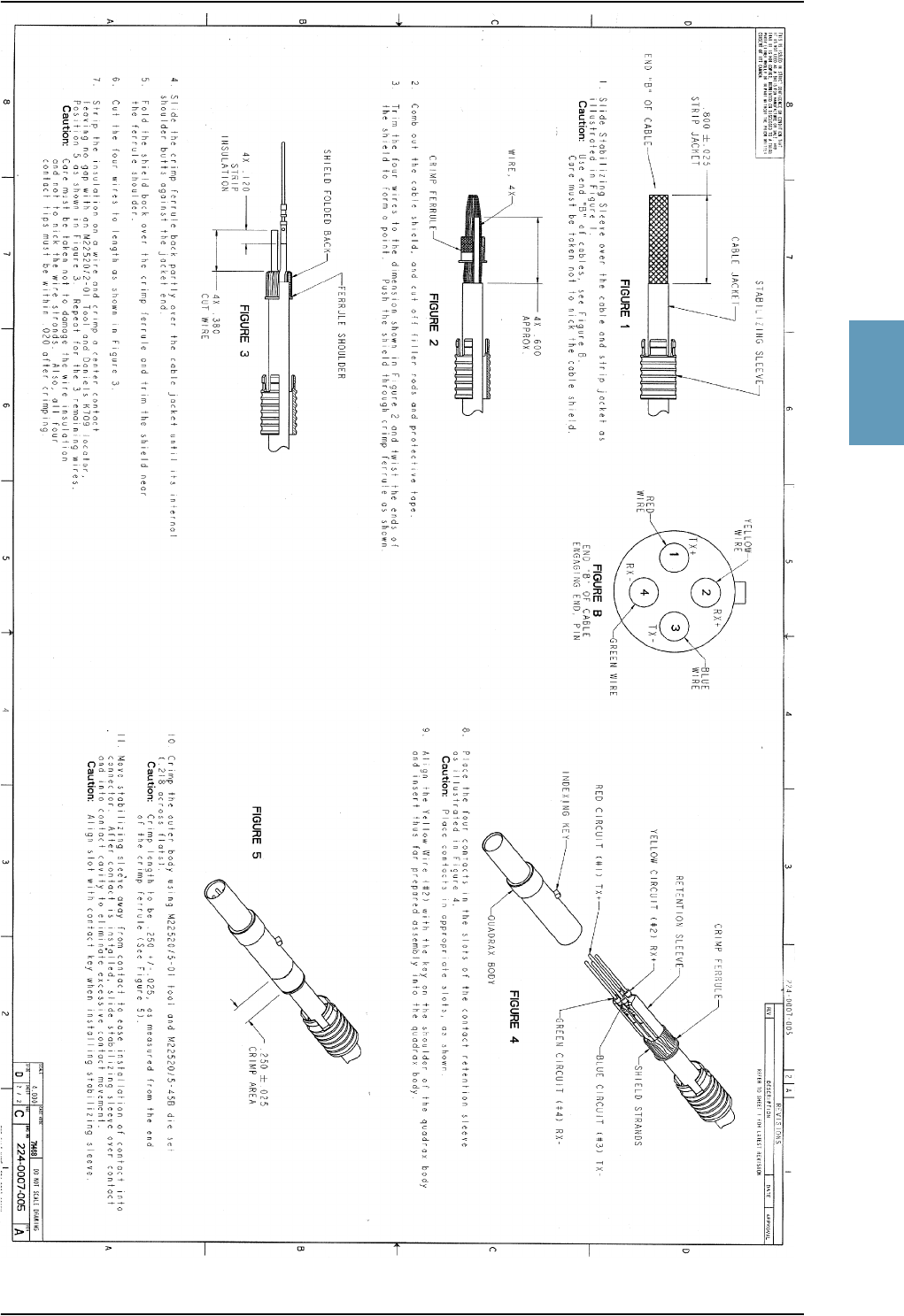
Figure 3-14: Contact Assembly: Quadrax Pin size 5 special: ITT Cannon 244-0011-001
HPA Tray Connector
3-16 Chapter 3: Equipment Drawings TT98-113625-D
3.12 HPA Tray Connector
Figure 3-15: HPA Tray Connector
HSU Tray
TT98-113625-D Chapter 3: Equipment Drawings 3-17
3333
3.13 HSU Tray
Figure 3-16: Outline Drawing: Tray for HSU

HSU Tray Connector
3-18 Chapter 3: Equipment Drawings TT98-113625-D
3.14 HSU Tray Connector
Figure 3-17: HSU Tray Connector, page 1 of 2
HSU Tray Connector
TT98-113625-D Chapter 3: Equipment Drawings 3-19
3333
Figure 3-18: HSU Tray Connector, page 2 of 2

HSU Tray Connector
3-20 Chapter 3: Equipment Drawings TT98-113625-D

TT98-113625-D 4-1
Chapter 4
4444
Connectors and Pin-out 4
4.1 TT-5035A Satellite Data Unit
4.1.1 Connectors on SDU
There are three connectors on the SDU:
• Maintenance (front connector):
Interface to PC and Handset for maintenance purposes.
A 15 pin Female Sub-D Filter connector
• ARINC 404 (rear connector):
Interfaces to Aircraft and SATCOM interconnections.
An ARINC 404 Shell Size 2 Receptacle.
• Configuration Module (rear, inside connector):
A 9 pin Sub-D Female Connector. This is an internal connector used only as
interface to the Configuration Module.

TT-5035A Satellite Data Unit
4-2 Chapter 4: Connectors and Pin-out TT98-113625-D
4.1.2 SDU Front Connector
Connector Drawing
Functions
The front connector is a 15 pin Female Sub-D Filter connector, and contains the
following interfaces:
• EIA/TIA-232-E PC port
• 4-Wire Thrane & Thrane Handset
• RS-485 Data interface for T&T Handset
• +12 V DC for powering the Handset
• Write Enable Input for Configuration Module.
Figure 4-1: SDU Front Connector,
Face View of Engaging End. (DB15F)
9
8
1
15

TT-5035A Satellite Data Unit
TT98-113625-D Chapter 4: Connectors and Pin-out 4-3
4444
Pin-out for SDU Front Connector
Pin. No. Pin Name
FP1 Maintenance Handset Audio In Hi
FP2 Maintenance Handset Audio In Lo
FP3 Maintenance Handset Audio Out Hi
FP4 Maintenance Handset Audio Out Lo
FP5 Signal Ground SGND
FP6 Maintenance Handset RS-485 Data A
FP7 Maintenance Handset RS-485 Data B
FP8 +12 V DC/120 mA
FP9 GND, Power Return (for +12 V DC)
FP10 PC EIA/TIA-232-E RxD Output
FP11 PC EIA/TIA-232-E TxD Input
FP12 PC EIA/TIA-232-E CTS Output
FP13 PC EIA/TIA-232-E RTS Input
FP14 GND
FP15 Configuration Module Write Enable In
Table 4-1: Pin-out for SDU Front Connector
TT-5035A Satellite Data Unit
4-4 Chapter 4: Connectors and Pin-out TT98-113625-D
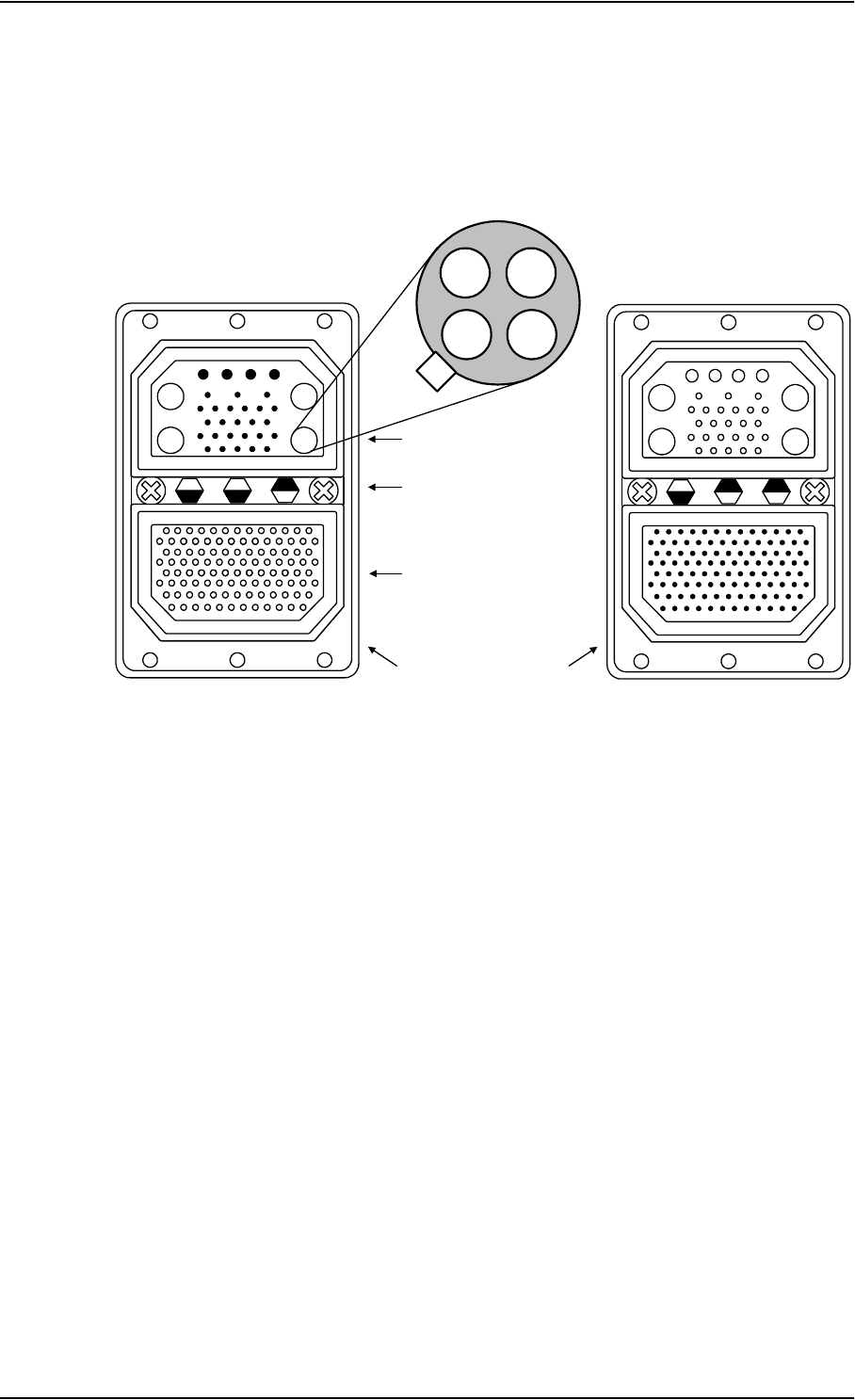
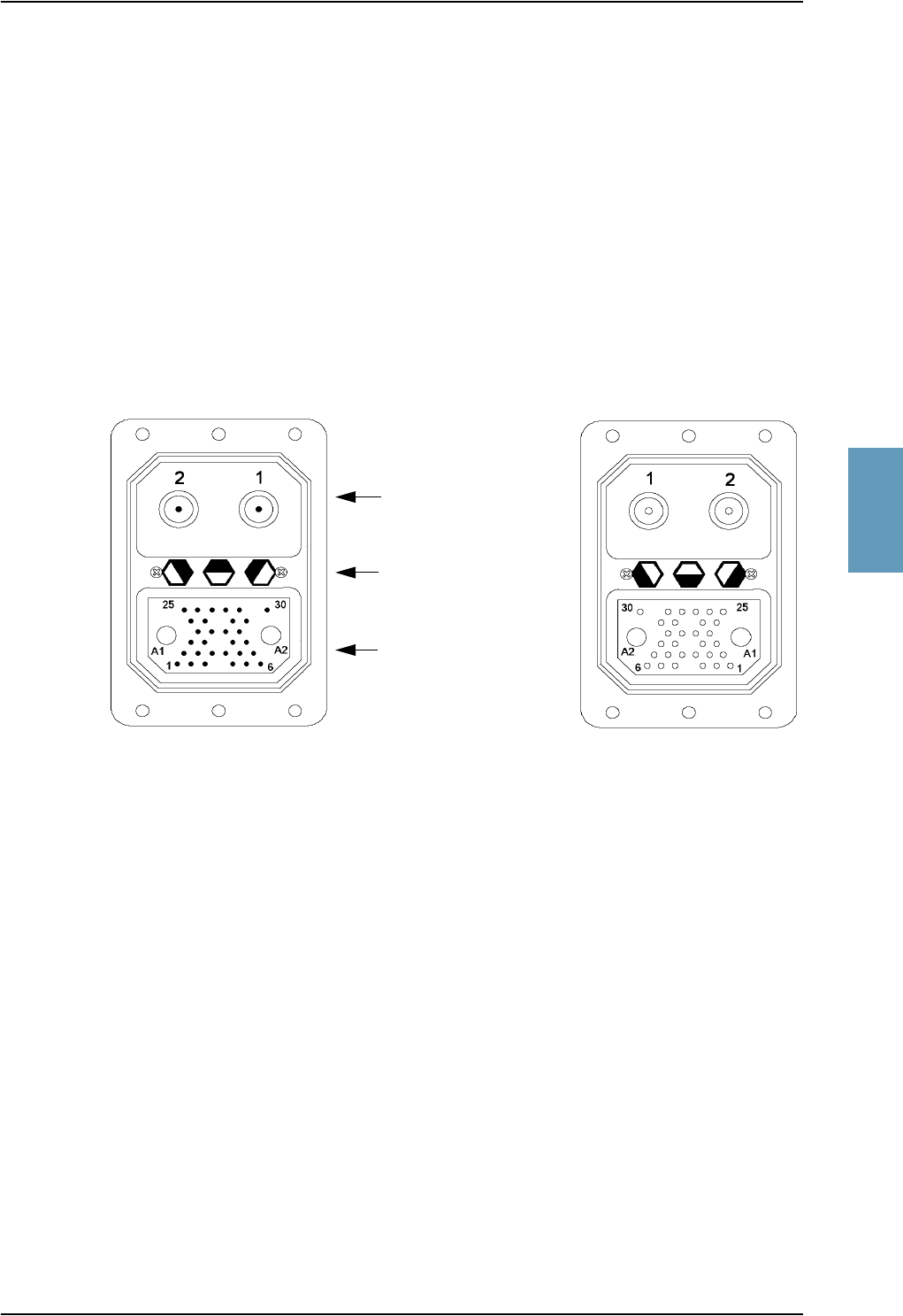
4.1.3 SDU Rear Receptacle
Connector Drawing
Figure 4-2: SDU Rear Receptacle and Mating Plug in Tray, Engaging End
A3A4
A1A2
41
13 8
24 19
75
18 14
29 25
1
25 13
40
67
94
106
52
79
12
Top Plug (TP) Insert
Bottom Plug (BP) Insert
Index Pin Code 04
Light areas are key holes
View: Engaging End
34
12
Quadrax Ethernet Insert
in A3
A3 A4
A1 A2
41
138
2419
75
1814
2925
112
2513
40
67
94 106
52
79
SDU Rear Receptacle Mating Plug in Tray

TT-5035A Satellite Data Unit
TT98-113625-D Chapter 4: Connectors and Pin-out 4-5
4444
Functions, Top Plug
The Top Plug (TP) connects the following signals:
Power, RF Interfaces and Antenna Modem:
• +28 V DC Power + chassis ground
• +28 V DC/600 mA 4-wire handset supply
• Remote ON/OFF (nON)
• RF Tx signal to HPA
• RF Rx signal from DLNA
• Antenna Modem Interface
Handset interfaces (analog):
• 4 analog four wire interfaces for Thrane & Thrane Handsets Systems (incl.
+28 V DC Handset supply with nON/OFF power supply control)
Voice/Fax/Modem interfaces:
• 2 VOICE/FAX/MODEM/STU-III, analog 2-wire standard POTS interfaces

TT-5035A Satellite Data Unit
4-6 Chapter 4: Connectors and Pin-out TT98-113625-D
Functions, Bottom Plug
The Bottom Plug connects the following signals:
Aircraft Avionics Interfaces:
• 24 bit discrete hardwire strapped ICAO address
• 2 high speed ARINC 429 Inertial Reference System (IRS) or
• 2 high or low speed ARINC 429 Attitude and Heading Reference System
(AHRS)
• 2 high or low ARINC 429 Communication Management Units (ACARS/CMU)
• 2 low speed ARINC 429 Cabin Packet-mode Data Function (CPDF)
• 3 high or low speed ARINC 429 MCDU/FMS (1 output, 2 inputs) or 1 high or
low speed ARINC 429 AES ID input (ICAO address, for future use)
• 2 Discrete inputs for “Weight On Wheels”
• Discrete Inputs/Outputs for WH-10/MagnaStar AIU control or, for future use,
Cockpit Voice
High Speed Interfaces:
• 1 MPDS RS-422, with RS-422 CTS/RTS Hardware Handshake
• 1 Euro ISDN S-bus connection
SATCOM Interfaces:
• 1 RS-422 Multi Control HPA Interface (Tx)
• 1 RS-422 BITE/Status HPA Interfaces (Rx)
• 1 Discrete HPA Remote nON/OFF output
Maintenance Interfaces:
• 1 Discrete SDU Hardware Reset
Handset interfaces (digital):
• 4 RS-485 data interfaces for Thrane & Thrane Handsets
Other interfaces:
• 1 RS-422 SIMCARD Reader Interface (future use)
• 3 Annunciators for: “Service Available”, “Call” and “FAX” -annunciator
• 3 ATE pins (Automatic Test Equipment) - not used

TT-5035A Satellite Data Unit
TT98-113625-D Chapter 4: Connectors and Pin-out 4-7
4444
Pin-out for SDU Rear Receptacle (Top Plug)
Table 4-2: Pin-out for SDU Rear Receptacle (Top Plug)
Pin No. Pin Name
TP A1 RF Rx input from DLNA
12 V DC power to DLNA (Coax)
TP A2 RF Tx output to HPA (Coax)
TP A3.1 Tx + 10BaseT Ethernet
(Quadrax pin 1)
TP A3.2 Rx + 10BaseT Ethernet
(Quadrax pin 2)
TP A3.3 Tx - 10BaseT Ethernet
(Quadrax pin 3)
TP A3.4 Rx - 10BaseT Ethernet
(Quadrax pin 4)
TP A4 Antenna Modem Interface (Coax)
TP1 +28 V DC Power
TP2 GND, Power Return
TP3 Chassis Ground and Handset
Power Return
TP4 +28 V DC/600 mA Handset
Supply
TP5 Remote ON/OFF (nON)
TP6 2-Wire Voice/Fax/Modem #5
(Ring)
TP7 2-Wire Voice/Fax/Modem #6
(Ring)
TP8 2-Wire Voice/Fax/Modem #6
(Tip)
TP9 Not Connected
TP10 Handset #1 Audio In Hi /
(For future use: Cockpit Voice
Audio #1 In Hi)
TP11 Handset #1 Audio In Lo /
(For future use: Cockpit Voice
Audio #1 In Lo)
TP12 Handset #1 Audio Out Hi /
(For future use: Cockpit Voice
Audio #1 Out Hi)
TP13 Handset #1 Audio Out Lo /
(For future use: Cockpit Voice
Audio #1 Out Lo)
TP14 Not Connected
TP15 Handset #2 Audio In Hi /
(For future use: Cockpit Voice
Audio #2 In Hi)
TP16 Handset #2 Audio In Lo /
(For future use: Cockpit Voice
Audio #2 In Lo)
TP17 Handset #2 Audio Out Hi /
(For future use: Cockpit Voice
Audio #2 Out Hi)
TP18 Handset #2 Audio Out Lo /
(For future use: Cockpit Voice
Audio #2 Out Lo)
TP19 2-Wire Voice/Fax/Modem #5
(Tip)
TP20 AGND
TP21 Handset #3 Audio In Hi
TP22 Handset #3 audio In Lo
TP23 Handset #3 audio Out Hi
TP24 Handset #3 audio Out Lo
TP25 Do not connect!
(+12 V DC / 25 mA)
TP26 Handset #4 audio In Hi
TP27 Handset #4 audio In Lo
TP28 Handset #4 audio Out Hi
TP29 Handset #4 audio Out Lo
Pin No. Pin Name

TT-5035A Satellite Data Unit
4-8 Chapter 4: Connectors and Pin-out TT98-113625-D
Pin-out for SDU Rear Receptacle (Bottom Plug)
Pin No. Pin Name
BP1 ICAO Address Bit #1 (MSB)
BP2 ICAO Address Bit #2
BP3 ICAO Address Bit #3
BP4 ICAO Address Bit #4
BP5 ICAO Address Bit #5
BP6 ICAO Address Bit #6
BP7 ICAO Address Bit #7
BP8 ICAO Address Bit #8
BP9 ICAO Address Bit #9
BP10 ICAO Address Bit #10
BP11 ICAO Address Bit #11
BP12 ICAO Address Bit #12
BP13 ICAO Address Bit #13
BP14 ICAO Address Bit #14
BP15 ICAO Address Bit #15
BP16 ICAO Address Bit #16
BP17 ICAO Address Bit #17
BP18 ICAO Address Bit #18
BP19 ICAO Address Bit #19
BP20 ICAO Address Bit #20
BP21 ICAO Address Bit #21
BP22 ICAO Address Bit #22
BP23 ICAO Address Bit #23
BP24 ICAO Address Bit #24
BP25 ICAO Address Common
BP26 Data from primary IRS 429 A /
Data from primary AHRS 429 A
BP27 Data from primary IRS 429 B /
Data from primary AHRS 429 B
BP28 Data from second. IRS 429 A /
Data from second. AHRS 429 A
BP29 Data from second. IRS 429 B /
Data from second. AHRS 429 B
BP30 Data bus from MCDU / FMS #2 /
AES ID input 429 A (future use)
BP31 Data bus from MCDU / FMS #2 /
AES ID input 429 B (future use)
BP32 Data bus from CPDF #1 429 A/
HSU control input
BP33 Data bus from CPDF #1 429 B/
HSU control input
BP34 Data bus to CPDF #1 429 A/
HSU control output
BP35 Data bus to CPDF #1 429 B/
HSU control output
BP36 Data bus from CPDF #2 429 A
BP37 Data bus from CPDF #2 429 B
BP38 Data bus to CPDF #2 429 A
BP39 Data bus to CPDF #2 429 B
BP40 Data bus from
ACARS/CMU #1 429 A
BP41 Data bus from
ACARS/CMU #1 429 B
BP42 Data bus to
ACARS/CMU #1 & #2 429 A
BP43 Data bus to
ACARS/CMU #1 & #2 429 B
BP44 Data bus from
ACARS/CMU #2 429 A
BP45 Data bus from
ACARS/CMU #2 429 B
Pin No. Pin Name

TT-5035A Satellite Data Unit
TT98-113625-D Chapter 4: Connectors and Pin-out 4-9
4444
Pin No. Pin Name
BP46 Data bus from MCDU /
FMS #1 429 A
BP47 Data bus from MCDU /
FMS #1 429 B
BP48 Data bus to MCDU /
FMS #1 & #2 429 A
BP49 Data bus to MCDU /
FMS #1 & #2 429 B
BP50 Reserved for Weight-On-Wheels
Input #1
BP51 Reserved for Weight-On-Wheels
Input #2
BP52 For future use: CP Voice Chime
Signal Contact #1;
Current from Chime
BP53 For future use: CP Voice Chime
Signal Contact #2;
Current to Chime
BP54 MagnaStar: Satcom Service
Unavailable
BP55 WH-10/MagnaStar:
Hook switch #3
BP56 HSU disable
BP57 HPA remote nON/OFF output
BP58 MPDS TxD-B RS-422 (I)
BP59 MPDS TxD-A RS-422 (I)
BP60 MPDS RxD-B RS-422 (O)
BP61 MPDS RxD-A RS-422 (O)
BP62 MPDS RTS-B RS-422 (I)
BP63 MPDS RTS-A RS-422 (I)
BP64 MPDS CTS-B RS-422 (O)
BP65 MPDS CTS-A RS-422 (O)
BP66 ISDN RxP (c)
BP67 ISDN TxP (d)
BP68 ISDN TxN (e)
BP69 ISDN RxN (f)
BP70 Future use: SIMCARD Reader
Control Output B, RS-422
BP71 Future use: SIMCARD Reader
Control Output A, RS-422
BP72 Future use: SIMCARD Reader Data
Input B, RS-422
BP73 Future use: SIMCARD Reader Data
Input A, RS-422
BP74 Do not connect! (ATE 1)
BP75 Do not connect! (ATE 2)
BP76 Do not connect! (ATE 3)
BP77 SDU Reset, Active Low
BP78 HPA Control Output A, RS-422
BP79 HPA Control Output B, RS-422
BP80 HPA Data/BITE Input A, RS-422
BP81 HPA Data/BITE Input B, RS-422
BP82 WH-10/MagnaStar Hook Switch #1
or, for future use, CP Voice Call
Cancel Input #1 (Discrete I)
BP83 WH-10/MagnaStar Ringer Output
A1 or, for future use, CP Voice Mic
On Input #1 (Discrete I/O)
BP84 WH-10/MagnaStar Ringer Output
B1 or, for future use, CP Voice Call
Light Output #1 (Discrete O)
BP85 WH-10/MagnaStar Hook Switch #2
or, for future use, CP Voice Call
Cancel Input #2 (Discrete I)
BP86 WH-10/MagnaStar Ringer Output
A2 or, for future use, CP Voice Mic
On Input #2 (Discrete I/O)
Pin No. Pin Name

TT-5035A Satellite Data Unit
4-10 Chapter 4: Connectors and Pin-out TT98-113625-D
Table 4-3: Pin-out for SDU Rear Receptacle (Bottom Plug)
Pin No. Pin Name
BP87 WH-10/MagnaStar Ringer Output
B2 or, for future use, CP Voice Call
Light Output #2 (Discrete O)
BP88 Chime/ Lamps Inhibit Input
(Discrete I)
BP89 WH-10/MagnaStar Ringer Output
A3 or Service Available
Annunciator (Discrete I/O)
BP90 WH-10/MagnaStar Ringer Output
B3
BP91 For future use: CP Voice Chime
Reset Input #1 (Discrete I)
BP92 Call Annunciator (Discrete I/O)
BP93 Fax Annunciator (Discrete Output)
BP94 4-Wire Handset #1
RS-485 Data A
BP95 4-Wire Handset #1
RS-485 Data B
BP96 4-Wire Handset #2
RS-485 Data A
BP97 4-Wire Handset #2
RS-485 Data B
BP98 4-Wire Handset #3
RS-485 Data A
BP99 4-Wire Handset #3
RS-485 Data B
BP100 4-Wire Handset #4
RS-485 Data A
BP101 4-Wire Handset #4
RS-485 Data B
BP102 MPDS DTR-B RS-422 (I)
BP103 MPDS DTR-A RS-422 (I)
BP104 MPDS DCD-B RS-422 (O)
BP105 MPDS DCD-A RS-422 (O)
BP106 Port 1 GND
Pin No. Pin Name
TT-5014A High Power Amplifier
TT98-113625-D Chapter 4: Connectors and Pin-out 4-11
4444
4.2 TT-5014A High Power Amplifier
4.2.1 HPA Rear Receptacle
The HPA has one connector:
An ARINC 404, shell size 2, rear receptacle, used for connection to the antenna
system and the SDU.
Connector Drawing
Functions
The Top Plug connects the following signals:
• RF Tx signal to DLNA
• RF Tx signal from SDU
The Bottom Plug connects the following signals:
• +28 V DC Power (Aircraft Power Bus)
• Chassis ground
• ARINC 429 Tx and Rx connections for interfacing to ARINC 741 antennas
• Remote ON/OFF (nON) from SDU
• RS-422 data interface to SDU
Figure 4-3: HPA Receptacle, Face View of Engaging End. Index Code is 08
Index pin code 08
Light areas are key holes
Top plug (TP)
Bottom plug (BP)
HPA Rear Receptacle Mating Plug in Tray

TT-5014A High Power Amplifier
4-12 Chapter 4: Connectors and Pin-out TT98-113625-D
Pin-out for HPA Receptacle
Table 4-5: Pin-out for HPA Receptacle (Bottom Plug)
Top Pi n Pin Name
TP1 RF Tx output to DLNA
TP2 RF Tx input from SDU
Table 4-4: Pin-out for HPA Receptacle (Top Plug)
Bottom
Pin Pin Name
BP A1 +28 V DC Power
BP A2 GND, Power Return
BP1 ATE 1
BP2 ATE 2
BP3 ATE 3
BP4 ATE 4
BP5 Spare
BP6 nON
BP7 Spare
BP8 A429 Tx A
BP9 A429 Tx B
BP10 A429 Tx A
BP11 A429 Tx B
BP12 Spare
BP13 A429 Rx1 A
BP14 A429 Rx1 B
BP15 A429 Rx2 A
BP16 A429 Rx2 B
BP17 HPA Mute 1 A
BP18 HPA Mute 1 B
BP19 HPA Mute 2 A
BP20 HPA Mute 2 B
BP21 Spare
BP22 Spare
BP23 Spare
BP24 Spare
BP25 RS-422 Tx A, HPA
Data/BITE Output A,
from HPA to SDU
BP26 RS-422 Tx B, HPA
Data/BITE Output B,
from HPA to SDU
BP27 RS-422 Rx A, HPA Control
Input A, from SDU to HPA
BP28 RS-422 Rx B, HPA Control
Input B, from SDU to HPA
BP29 Spare
BP30 Chassis
Bottom
Pin Pin Name
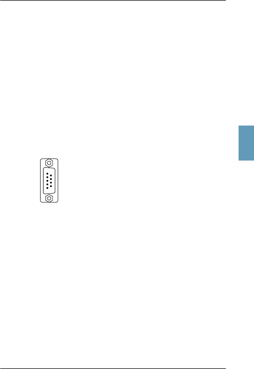
TT-5038A HSU (Optional)
TT98-113625-D Chapter 4: Connectors and Pin-out 4-13
4444
4.3 TT-5038A HSU (Optional)
4.3.1 Connectors on HSU
There are two connectors on the HSU:
• Maintenance (front connector):
Interface to PC for maintenance purposes.
A 9 pin female Sub-D connector.
• ARINC 404 (rear connector):
Interfaces to Aircraft and SATCOM interconnections.
An ARINC 404 Shell Size 2 Receptacle.
4.3.2 HSU Front Connector
Connector Drawing
Functions
The front connector is a 9 pin Female Sub-D connector, and contains the
following interfaces:
• EIA/TIA-232-E port for #1 RS-232 PC interface
• #2 I/F Disable Input
Figure 4-4: HSU Front Connector.
Face View of Engaging End.
9 pin
SUB-D
female
6
5
1
9
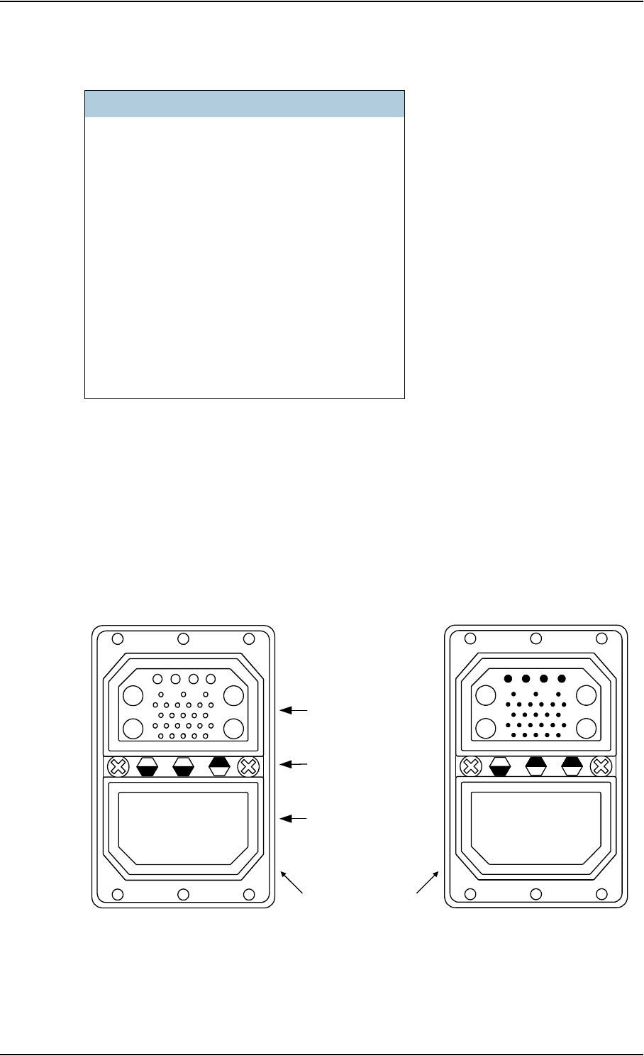
TT-5038A HSU (Optional)
4-14 Chapter 4: Connectors and Pin-out TT98-113625-D
Pin-out for HSU Front Connector
4.3.3 HSU Rear Receptacle
Connector Drawing
Pin no. Pin Name
FP1 Not used
FP2 #1 RxD Output (EIA/TIA-232-E)
FP3 #1 TxD Input (EIA/TIA-232-E)
FP4 #2 I/F Disable Input
FP5 #1 GND (EIA/TIA-232-E)
FP6 #1 +12 V DC (to pull up FP4)
FP7 Not Used
FP8 Not Used
FP9 Not used
Table 4-6: Pin-out for HSU Front Connector
Figure 4-5: HSU Rear Receptacle and Mating Plug in Tray, Engaging End.
A3A4
A1A2
41
13 8
24 19
75
18 14
29 25
Top Plug (TP) Insert
Bottom Plug, Blind
Index Pin Code 04
Light areas are key holes
View: Engaging End
A3 A4
A1 A2
41
138
2419
75
1814
2925
HSU Rear Receptacle Mating Plug in Tray

TT-5038A HSU (Optional)
TT98-113625-D Chapter 4: Connectors and Pin-out 4-15
4444
Functions
The Top Plug of the HSU rear receptacle connects the following signals:
Power & RF Interfaces:
• +28 V DC and chassis ground
• RF Tx signal to HPA
• RF Rx signal from DLNA
User Interfaces:
• MPDS, 10BaseT Ethernet
• MPDS, EIA/TIA-232 with CTS/RTS Hardware Handshake
• Euro ISDN S-bus connection
Control & Maintenance Interfaces:
• EIA/TIA-232 PC interface (#2)
• ARINC 429 High Speed HSU Control Interface
• HSU Failure Discrete Output
• 1 MPDS Service Available Output
• 1 ISDN Service Available Output
• HSU Disable Discrete Input
• 2 ATE Discrete inputs

TT-5038A HSU (Optional)
4-16 Chapter 4: Connectors and Pin-out TT98-113625-D
Pin-out for HSU Rear Receptacle
Table 4-7: Pin-out for HSU Rear Receptacle
Pin Function
TP A1 RF Rx input from DLNA
TP A2 RF Tx output to HPA
TP A3 10BaseT Rx output
(Center: RxD+)
TP A4 10BaseT Tx input
(Center: TxD+)
TP1 +28 V DC Power
TP2 GND, Power Return
TP3 Chassis Ground
TP4 Not Used
TP5 #2 GND (EIA/TIA-232-E)
TP6 #2 TxD Input
(EIA/TIA-232-E)
TP7 #2 RxD Output
(EIA/TIA-232-E)
TP8 HSU Disable, Discrete Input
TP9 ATE #1, Discrete Input
TP10 ATE #2, Discrete Input
TP11 MPDS TxD Input
(EIA/TIA-232-E)
TP12 MPDS RxD Output
(EIA/TIA-232-E)
TP13 MPDS RTS Input
(EIA/TIA-232-E)
TP14 MPDS CTS Output
(EIA/TIA-232-E)
TP15 MPDS DTR Input
(EIA/TIA-232-E)
TP16 MPDS DCD Output
(EIA/TIA-232-E)
TP17 MPDS DSR Output
(EIA/TIA-232-E)
TP18 MPDS GND
(EIA/TIA-232-E)
TP19 Data bus output to SDU
(ARINC 429-A)
TP20 Data bus output to SDU
(ARINC 429-B)
TP21 Data bus input from SDU
(ARINC 429-A)
TP22 Data bus input from SDU
(ARINC 429-B)
TP23 ISDN Rx+ (c) input
TP24 ISDN Tx+ (d) output
TP25 ISDN Tx- (e) output
TP26 ISDN Rx- (f) input
TP27 HSU Failure, Discrete Output
(Lamp Type)
TP28 ISDN Service Available,
Discrete Output (Lamp Type)
TP29 MPDS Service Available,
Discrete Output (Lamp Type)
Pin Function
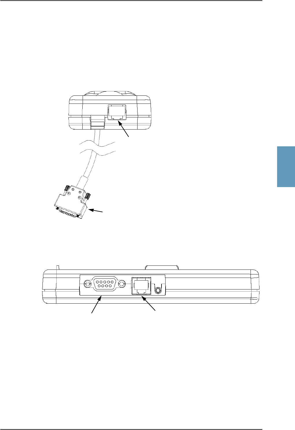
Cradle Connectors
TT98-113625-D Chapter 4: Connectors and Pin-out 4-17
4444
4.4 Cradle Connectors
4.4.1 Connectors on 4-Wire Cradle
There are four connectors on the 4-wire cradle, two on the side of the cradle and
two at the end:
Figure 4-6: 4-Wire Cradle Connectors, End View of Cradle
Figure 4-7: 4-Wire Cradle Connectors, Side View of Cradle
4-Wire Handset Connection
SDU Connection
2-Wire Voice/Fax/Modem Connection
Headset Connection

Cradle Connectors
4-18 Chapter 4: Connectors and Pin-out TT98-113625-D
4.4.2 4-Wire Connector to SDU
Connector Drawing
Functions
The 15 pin Sub-D male connector on the “pigtail” at the end of the 4-wire cradle
connects the following signals on the SDU:
Handset interface (analog):
• analog 4-wire interface (incl. +28 V DC Handset supply)
Handset interface (digital):
• RS-485 data interface
Voice/Fax/Modem interface:
• Voice/Fax/Modem/STU-III, analog 2-wire standard POTS interface
OR
Maintenance handset interface:
• Maintenance 4-wire handset connection to SDU front connector
Figure 4-8: 4-Wire Cradle Connector
(DB15M). View: Solder Side
19
15
8
View: Solder side
DB15 Male

Cradle Connectors
TT98-113625-D Chapter 4: Connectors and Pin-out 4-19
4444
Pin-out for DB15 Connector
The 4-wire cradle connector for connection to the SDU has the following pin-out:
Table 4-8: Pin-out for 15 Pin Sub-D Male Connector on “pigtail” in 4-Wire Cradle
Pin Function
12 wire Tip
(Fax/PC_modem/Auxiliary)
22 wire Ring
(Fax/PC_modem/Auxiliary)
3GND
4+28VDC
5 GND, Power Return
6 SDU Audio in +
7 SDU Audio in -
8 GND
9 GND
10 RS-485 Data A
11 RS-485 Data B
12 GND
13 SDU Audio out +
14 SDU Audio out -
15 NC
Pin Function
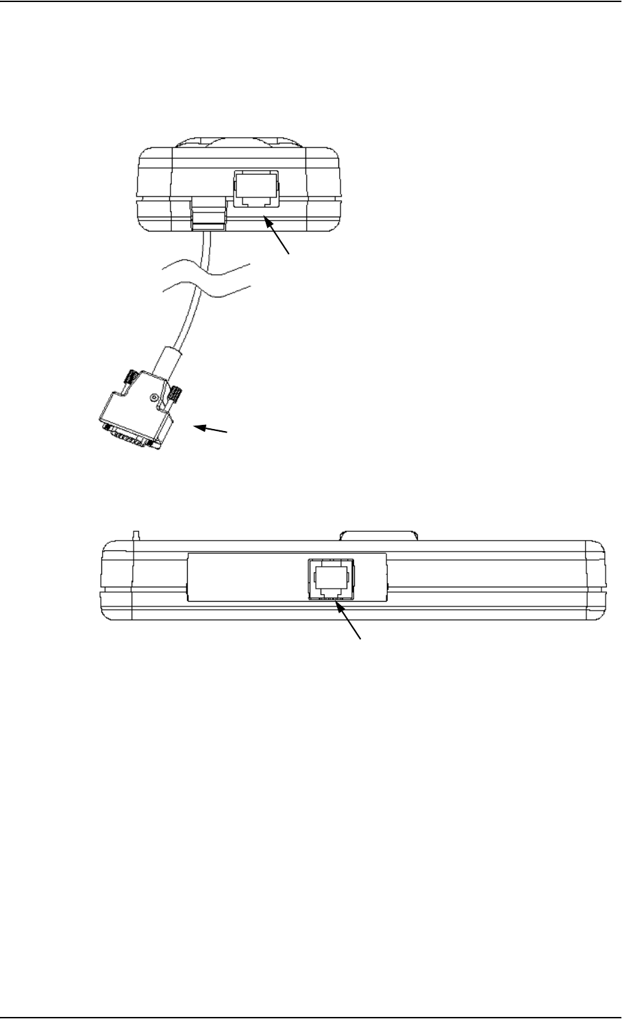
Cradle Connectors
4-20 Chapter 4: Connectors and Pin-out TT98-113625-D
4.4.3 Connectors on 2-Wire Cradle
There are three connectors on the 2-wire cradle, one at the side and two at the end:
Figure 4-9: 2-Wire Cradle Connectors, End View of Cradle
Figure 4-10: 2-Wire Cradle Connectors, Side View of Cradle
2-Wire Handset Connection
SDU Connection
2-Wire VoiceFax/Modem Connection

Cradle Connectors
TT98-113625-D Chapter 4: Connectors and Pin-out 4-21
4444
4.4.4 2-Wire Connector to SDU
Connector Drawing
Functions
The 9 pin Sub-D male connector on the “pigtail” at the end of the 2-wire cradle
connects the following signals on the SDU:
• Voice/Fax/Modem/STU-III, analog 2-wire standard POTS interface
Pin-out for Cradle Connector
The 2-wire cradle connector for connection to the SDU has the following pin-out:
Figure 4-11: 2-Wire Cradle Connector
(DB9M). View: Solder Side
View: Solder side
DB9 Male
1
59
6
Pin Function
1 Auxiliary Tip
2 Auxiliary Ring
3Shield
4NC
5NC
6NC
7NC
8NC
9NC
Table 4-9: Pin-out for 9 Pin Sub-D Male
Connector on “pigtail” in 2-Wire Cradle.

Mating Connectors in Aircraft
4-22 Chapter 4: Connectors and Pin-out TT98-113625-D
4.5 Mating Connectors in Aircraft
Connection With SDU
The installation tray for the SDU is equipped with the following connector:
Connector Mating Connector Type
Front Panel Connector 15 pin SUB-D male
Rear I/O Connector ARINC 404 shell size 2 plug,
with the following contact arrangements:
Insert A (Top Plug): 33C4
• 4 #16 pin socket contacts
• 25 #20HD socket contacts
• 3 #5 coax socket contacts
• 1 #5 Quadrax socket contact
Insert B (Bottom Plug): 106
• 106 #22 pin contacts
ITT Cannon Part number DPX2NA-67322-463
Internal connector for
Configuration Module
9-pin SUB-D male
Table 4-10: Mating Connectors in Aircraft for SDU
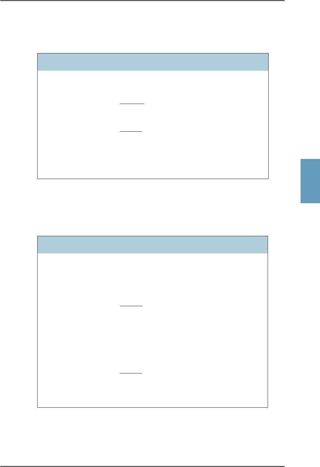
Mating Connectors in Aircraft
TT98-113625-D Chapter 4: Connectors and Pin-out 4-23
4444
Connection With HPA
The installation tray for the HPA is equipped with the following connector:
Connection With Optional HSU
The installation tray for the HSU is equipped with the following connector:
Connector Mating Connector Type
Rear I/O Connector ARINC 404 shell size 2 plug,
with the following contact arrangements:
Insert A (Top Plug): MC2
• 2 #1 coax socket contacts for RG142B
Insert B (Bottom Plug): 32C2
• 2 #5 socket contacts for AWG 8-10
• 30 #20 HD socket contacts for AWG 20-24
Radiall part number 616 697 173
Table 4-11: Mating Connector in Aircraft for HPA
Connector Mating Connector Type
Front Panel Connector 9 pin SUB-D male
Rear I/O Connector ARINC 404 shell size 2 plug with the following
contact arrangements:
Insert A (Top Plug): 33C4
• 4 #16 socket contacts
• 25 #20 socket contacts
• 2 #5 coax socket contacts
• 2 #5 Twinax socket contacts
Insert B (Bottom Plug): Blind
• Not used
ECS part number DSXN2PS33C45X00500
Table 4-12: Mating Connectors in Aircraft for HSU

Mating Connectors in Aircraft
4-24 Chapter 4: Connectors and Pin-out TT98-113625-D

TT98-113625-D 5-1
Chapter 5
5555
Installation 5
5.1 General
5.1.1 Overview
This chapter contains considerations and recommendations for installation of the
Aero-HSD+ System. Interconnect harness wiring and physical mounting must
satisfy all applicable regulations.
Note: Complete installation kits including wiring can be obtained through ECS
(Electronic Cable Specialists, Inc.). For information, contact
ECS, USA
Phone: +1 414.421.5300
Email: sales@ecsdirect.com
Homepage: www.ecsdirect.com
The Installation chapter is organized in the following sections:
•Mounting Considerations on page 5-4.
This section provides guidelines for the mechanical installation of the units in
the Aero-HSD+ system.
•Electrical Installation and Wiring on page 5-7.
This section provides wiring drawings and guidelines for the electrical
installation of the Aero-HSD+ system. It also lists the requirements to the
cables.
•Electrical Installation and Wiring, HSU on page 5-63.
This section provides wiring drawings and guidelines for the electrical
installation of the Aero-HSD+ system with an HSU installed. It also lists the
requirements to the cables.
•Recommended Cables on page 5-81.
This section provides lists of recommended cables and maximum cable lengths.
The information, drawings and wiring diagrams contained in this manual are
intended as a reference for engineering planning only. The drawings and wiring
diagrams contained herein do not represent any specific STC. It is the installer’s
responsibility to compose installation drawings specific to the aircraft. This
manual and the drawings and wiring diagrams contained herein may not be used
as a substitute for an STC.
Note: To ensure optimal performance from the Aero-HSD+ System, strict
adherence to the installation considerations found in this section must be
maintained.

General
5-2 Chapter 5: Installation TT98-113625-D
5.1.2 Minimum System
A minimum working system has at least:
• one TT-5035A SDU
• one TT-5035A-001 CM
• one TT-5014A HPA
• one handset and cradle, e.g. a TT-5620A 4-Wire Handset and a TT-5622A 4-
Wire Cradle.
• one antenna system. As antenna system, use either the AMT-50 Antenna
Subsystem or the HGA-7000 Antenna with a TT-5012A DLNA.
The following drawing shows the minimum installation required in the
Aero-HSD+ system.

General
TT98-113625-D Chapter 5: Installation 5-3
5555
Minimum System Drawing
Note: This drawing is an overview of which units to connect as a minimum. For
specific information on wiring, refer to the appropriate section of
Electrical Installation and Wiring on page 5-7 onwards.
Note: This example includes an HGA-7000 Antenna with a TT-5012A DLNA,
but the antenna system may as well be e.g. an AMT-50 subsystem.
Note: Another type of 4-wire handset or a 2-wire handset may be connected
instead of the Thrane & Thrane 4-wire handset.
Figure 5-1: Minimum System
TT-5014A
HPA
BP A2 GND, Power Return
28 V DC
Aircraft
Power Supply
BP30 Chassis
BP A1 +28 V DC Power
TT-5035A
SDU
TP2 GND, Power Return
TP5
28 V DC
Aircraft
Power Supply
TP3
TP1 +28 VDC Power
Chassis Ground and Handset Power Return
Remote ON/OFF (nON)
TP4
TP3
A BP94
B BP95
Hi TP12
Lo TP13
Hi TP10
Lo TP11
Full Feature Handset #1 RS-485 Data
Chassis Ground and Handset Power Return
+28 VDC / 600mA Handset Supply
Handset #1 Audio Out / Cockpit Voice Audio Out
Handset #1 Audio In / Cockpit Voice Audio In
RF Tx
HPA nON BP6
TP2
BP27
BP28
BP25
BP26
HPA CONTROL
BITE / STATUS
TP19
TP6
TP1
BP78
BP79
BP80
BP81
TP A2
BP57
NC
1
2
9
10
11
3
4
5
12
13
14
6
7
8
15
TT-5622A
CRADLE
1
2
9
10
11
3
4
5
12
13
14
6
7
8
15
TT-5620A
HANDSET
#1
Two-wire fax/modem Tip
Ring
RF Tx
TT-5012A
DLNA
X3 TX
X1 RX
X2 Ant
HGA-7000
J2 IF2
J1 IF1
GND
TP A1
TP A4
Built-in
BSU
BP1 ICAO MSB
BP2
BP3
BP4
BP5
BP6
BP7
BP8
BP9
BP10
BP11
BP12
BP13
BP14
BP15
BP16
BP17
BP18
BP19
BP20
BP21
BP22
BP23
BP24 ICAO LSB
BP25 ICAO common
IRS/AHRS A429 A, BP26
IRS/AHRS A429 B, BP27
IRS/AHRS
Strapped ICAO Address
RF Rx

Mounting Considerations
5-4 Chapter 5: Installation TT98-113625-D
5.2 Mounting Considerations
5.2.1 Overview
For optimum system performance, some guidelines on where to install or mount
the different components of the Aero-HSD+ System must be followed. Mounting
and placement details are included in this section.
For information on requirements to cables, see the individual sections in
Electrical Installation and Wiring on page 5-7 or Electrical Installation and
Wiring, HSU on page 5-63.
For information on recommended cable types and lengths, see Recommended
Cables on page 5-81.
Note: When mounting the units, make sure that there is enough space to
provide a sufficient bend radius for the cables. See the cable data sheet
for minimum bend radius.
5.2.2 SDU
Forced cooling is not recommended for the SDU.
• Place the SDU in a temperature controlled area (e.g. avionics bay).
• Place the SDU where the cooling air holes are not blocked. Note that cooling
air holes in the SDU are placed outside the recommended area for
ARINC 404A 3/8 ATR short units.
• Mount the SDU in an ARINC 404A 3/8 ATR short standard tray.
5.2.3 HSU
Forced cooling is not recommended for the HSU.
• Place the HSU in a temperature controlled area (e.g. avionics bay).
• Place the HSU where the cooling air holes are not blocked. Note that cooling
air holes in the HSU are placed outside the recommended area for
ARINC 404A 1/4 ATR short units.
• Mount the HSU in an ARINC 404A 1/4 ATR short standard tray.

Mounting Considerations
TT98-113625-D Chapter 5: Installation 5-5
5555
5.2.4 Rx Power Splitter
If the Rx Power Splitter is to be mounted on a flat surface, mount it on a 3 mm
mounting plate to provide enough space for mounting of the connectors.
5.2.5 HPA
The HPA can be installed in a non-temperature controlled area.
The HPA is designed with built-in forced cooling (fans).
Internal temperature monitoring prevents damage caused by overheating.
Important! Respect the minimum clearance of 25 mm from top and bottom.
• Mount the HPA vertically on a panel to ensure maximum cooling. Mount the
HPA in an ARINC 404A 3/8 ATR short tray with oval cut-out as shown in
Figure 3-12: Outline Drawing: Tray for SDU and HPA.
• Install the HPA as close to the DLNA as possible.
The cable between the HPA and the DLNA must be a special low-loss coax
cable. See Wiring Antenna Systems on page 5-14 and the wiring drawings
Figure 5-5: Wiring HGA-7000 Antenna and TT-5012A DLNA and Figure
5-6: Wiring AMT-50 Subsystem.
5.2.6 DLNA
The DLNA can be installed in a non-temperature controlled area. The DLNA can
be mounted in an upright position.
• Install the DLNA as close to the antenna as possible.
• Place the DLNA with sufficient contact to the surface, respecting the max.
resistance of 3 mΩ. The DLNA can be mounted on a shelf or directly on the
fuselage.
Important! If the DLNA is mounted directly on fuselage, mount with
Cadmium plated washers between the DLNA and fuselage.
The coax cable between the DLNA and the antenna must be a low-loss coax cable.
See Wiring Antenna Systems on page 5-14 for requirements to the cable.
Figure 5-2: Mounting the Rx Power Splitter

Mounting Considerations
5-6 Chapter 5: Installation TT98-113625-D
5.2.7 Antenna
General Mounting Considerations
Refer to the antenna manual for details on mounting the antenna. Make sure all
requirements in the antenna mounting instructions are met.
Place the antenna with unobstructed view to the satellite.
WARNING! Respect a safety distance of minimum 6.6 feet (2 metres) of the
antenna when the system is transmitting, unless the antenna manual
or the specific system configuration presents different
requirements.
Note: The antenna installation must be in accordance with the aircraft
manufacturers requirements and/or FAA AC 43.13 - 1B/2A and
approved by the appropriate Civil Aviation Authorities.
Satcom filter
If the GPS antenna for the existing GPS receiver on board the aircraft does not
provide sufficient filtering it may be necessary to install a Satcom filter for the
GPS antenna.
Cables to the antennas
Be aware that the shorter the cable is, the better the system performance is.
Do not bend the cables to a radius smaller than the minimum bend radius stated
for the cables.
For further information on cables, see Wiring Antenna Systems on page 5-14,
Wiring Antenna Systems With HSU Installed on page 5-65 and
Recommended Cables on page 5-81

Electrical Installation and Wiring
TT98-113625-D Chapter 5: Installation 5-7
5555
5.3 Electrical Installation and Wiring
5.3.1 Wiring Symbols
Throughout the wiring section these common symbols are used:
Coax
Shield
Ground
Twisted
Twisted and shielded
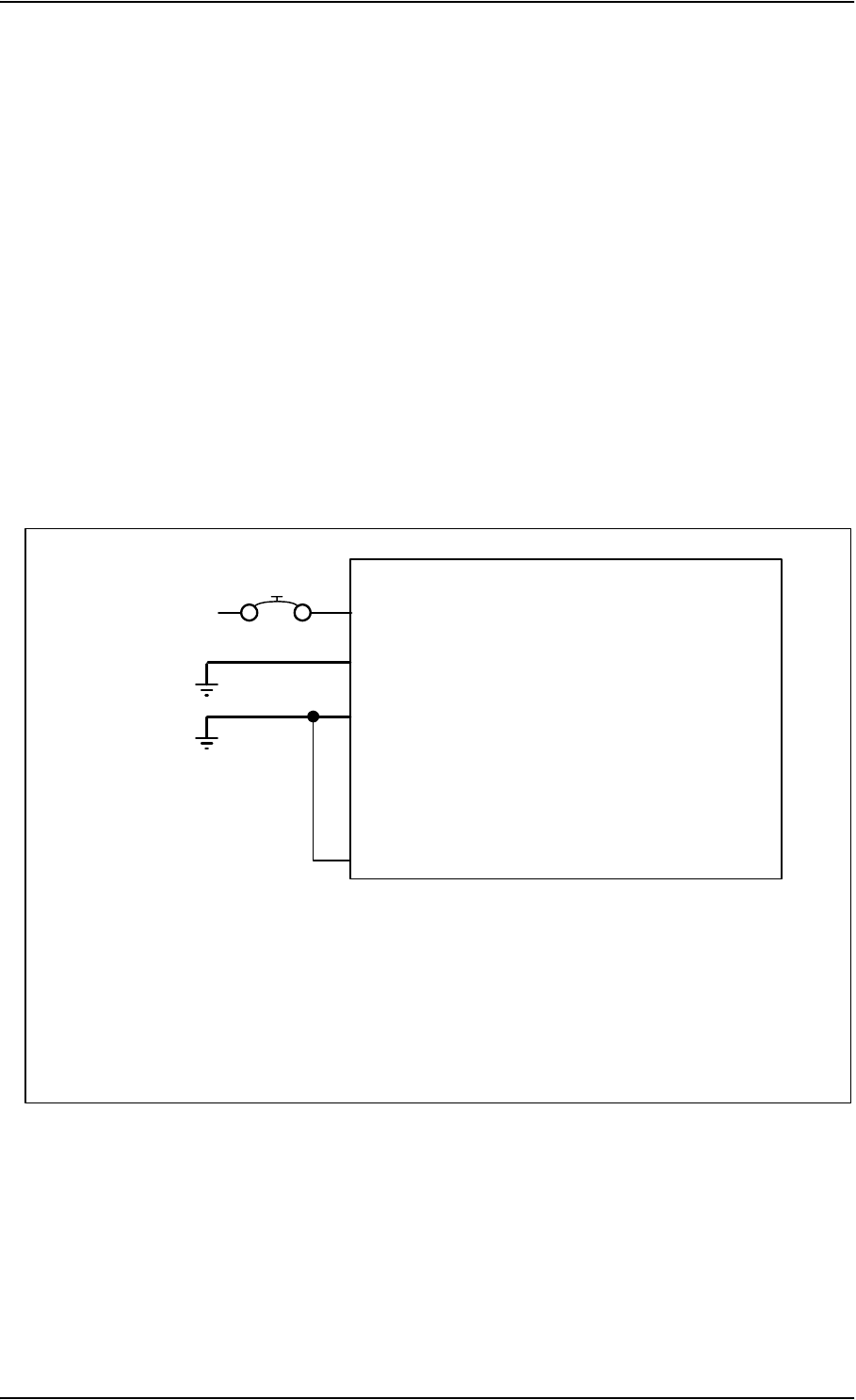
Electrical Installation and Wiring
5-8 Chapter 5: Installation TT98-113625-D
5.3.2 Wiring Power Supply
Important! Do not use the same 20 A circuit breaker for both the SDU and the
HPA. Use separate circuit breakers as described in this section, and
with the current rating stated here.
Wiring of Satellite Data Unit
The Aircraft Power Bus provides the electric power required to operate the SDU,
and a chassis connection to the aircraft chassis and the installation tray. The
+28 V DC Power wire must include a circuit breaker capable of carrying the
required current continuously under the required environmental conditions.
The following drawing shows the wiring of the SDU power supply.
Requirements to the wiring are stated in the notes on the drawing and in the
section Cable Requirements, SDU Power Supply on page 5-10.
Figure 5-3: Wiring SDU Power Supply
TT-5035A
SDU
[2] TP2 GND, Power Return
TP5
28VDC
Aircraft Power Bus
[1] Total resistance max. 200 mΩ incl. Circuit Breaker.
[2] Total resistance max. 25 mΩ .
[3] Directly to Aircraft chassis, max. 1 m cable length to prevent EMC problems and max. 25 mΩ resistance
[4] Recommended circuit breaker: Klixon 2TC series, 4 A current rating
[5] If SATCOM On/Off switch is required, TP5 is routed to an external switch to ground
TP3
TP1 +28 VDC Power
Chassis Ground and Handset Power Return
Remote ON/OFF (nON)
[4]
4A
[5]
20
AWG
[1]
[3]

Electrical Installation and Wiring
TT98-113625-D Chapter 5: Installation 5-9
5555
The following list shows the pins used for the SDU power supply.
+28 V DC Power (TP1)
It is essential to keep the line impedance below the specified limits. See Cable
Requirements, SDU Power Supply on page 5-10.
Reverse polarity protection is only guaranteed if the suggested circuit breaker is
used.
Required current capability for the Circuit Breaker: 48 W @ 17.3 V DC which
equals 2.8 A DC at the required environmental conditions.
A suitable circuit breaker would be Klixon 2TC series with 4 A current rating.
Important! Do not use the HPA 20 A circuit breaker for both the HPA and the
SDU.
Chassis Ground / Handset Power Return (TP3)
The Chassis connection makes sure that the HPA cabinet and the installation tray
has the same potential, and that there is a connection from the wiring shields to the
cabinet for EMC purposes.
Connect the wire directly to the installation tray, and to aircraft chassis.
TP3 also connects to the Handset Power Return.
Remote On/Off (nON) input (TP5)
The nON input is used to turn the SDU and the power supply to the handsets on
and off. Connection of this input to ground turns on the SDU and all other units in
the SATCOM system (Handsets, DLNA, HPA and HGA-7000 Antenna).
However, ARINC 741 Antennas and DLNAs are not turned off when the SDU is
turned off.
The electrical specifications are defined like the discrete WOW input type. Please
refer to Discrete type and description: on page 5-57.
SDU pin Name Description
TP1 +28 V DC Power +28 V DC Power input from Aircraft power bus.
TP2 GND, Power Return Aircraft Ground connection
TP3 Chassis Ground and
Handset Power Return
Chassis connection, connected to installation
tray and Aircraft chassis.
Also used for handset power return.
TP5 Remote ON/OFF (nON) Power On/Off for the SDU and handsets.
Table 5-1: Pins for SDU Power Supply

Electrical Installation and Wiring
5-10 Chapter 5: Installation TT98-113625-D
Cable Requirements, SDU Power Supply
Note: Maximum cable lengths are calculated and listed in the section Power
Cables, Allowed Cable Lengths on page 5-81.
Cablea
a. The cable numbers refer to the numbers stated on the wiring drawing in the section
Wiring of Satellite Data Unit on page 5-8.
Max. Resistance Other Requirements
[1]
(+28 V DC)
200 mΩ,
incl. circuit breaker
[2]
(GND, Power
Return)
25 mΩThe cable should be as short as possible.
[3]
(Chassis Ground)
25 mΩConnect directly to aircraft chassis.
Table 5-2: Requirements to SDU Power Cables

Electrical Installation and Wiring
TT98-113625-D Chapter 5: Installation 5-11
5555
Wiring of High Power Amplifier
The Aircraft power bus provides the electric power required to operate the HPA,
and a chassis connection to the aircraft chassis and the installation tray. The
+28 V DC Power wire must include a circuit breaker capable of carrying the
required current continuously under the required environmental conditions.
The following drawing shows the wiring of the HPA power supply.
Requirements to the wiring are stated in the notes on the drawing and in the
section Cable Requirements, HPA Power Supply on page 5-13.
Figure 5-4: Wiring HPA Power Supply
TT-5014A
HPA
[2] BP A2 GND, Power Return
28 V DC
Aircraft Power Bus
[1] Total resistance max. 100 mΩ incl. Circuit Breaker.
[2] Total resistance max. 25 mΩ.
[3] Directly to Aircraft chassis, max. 0.6 m cable length (AWG 20) to prevent EMC problems and
max. resistance 25 mΩ.
[4] Recommended circuit breaker: Klixon 2TC series, 20 A current rating.
[5] Must be shielded to prevent EMC problems.
BP30 Chassis
BP A1 +28 V DC Power
BP6 nON
[4]
20A
[1]
[3]
TT-5035A
SDU
BP57 [5]

Electrical Installation and Wiring
5-12 Chapter 5: Installation TT98-113625-D
The following list shows the pins used for the HPA power supply.
This section describes the installation requirements for HPA power supply
interface. The connection from the HPA to the Aircraft power bus normally goes
through the tray connector. The connector also supports other signals. For
information on pin-out, please refer to TT-5014A High Power Amplifier on
page 4-11.
+28 V DC Power
It is essential to keep the line impedance below the specified limits. See Cable
Requirements, HPA Power Supply on page 5-13.
Reverse polarity protection is only guaranteed if the suggested circuit breaker is
used.
Required current capability for the Circuit Breaker: 235 W @ 15.7 V DC, which
equals 15 A DC, at the required environmental conditions.
A suitable circuit breaker would be Klixon 2TC series with 20 A current rating.
Chassis (BP30)
The Chassis connection makes sure that the HPA cabinet and the installation tray
has the same potential, and that there is a connection from the wiring shields to
cabinet for EMC purposes.
Connect the wire directly to the installation tray, and to aircraft chassis.
nON (BP6)
The nON input is used by the SDU (BP57) to turn the HPA on and off. The SDU
connects this input to ground to turn on the HPA.
HPA pin Name Description
BP A1 +28 V DC Power +28 V DC Power input from Aircraft power bus.
BP A2 GND, Power Return Aircraft ground connection.
BP30 Chassis Chassis connection, connected to installation
tray and Aircraft chassis.
BP6 nON HPA power on/off controlled by the SDU.
Table 5-3: Pins for HPA Power Supply
SDU pin Name Description
BP57 HPA remote nON/OFF output Power On/Off control for the HPA.
Table 5-4: Pin for Remote HPA Power on/off by SDU

Electrical Installation and Wiring
TT98-113625-D Chapter 5: Installation 5-13
5555
Cable Requirements, HPA Power Supply
Note: Maximum cable lengths are calculated and listed in the section Power
Cables, Allowed Cable Lengths on page 5-81.
Cablea
a. The cable numbers refer to the numbers stated on the wiring drawing in the section
Wiring of High Power Amplifier on page 5-11.
Max. Resistance Other Requirements
[1]
(+28 V DC Power)
100 mΩ,
incl. circuit breaker
[2]
(GND, Power Return)
25 mΩ
[3]
(Chassis)
25 mΩConnect directly to aircraft chassis.
[5]
(nON)
- Must be shielded to avoid EMC
problems.
Table 5-5: Requirements to HPA Power Cables

Electrical Installation and Wiring
5-14 Chapter 5: Installation TT98-113625-D
5.3.3 Wiring Antenna Systems
Cable Losses
During installation, it is important that you write down the cable losses of the RF
cables. For this purpose, you may use the last part of the check sheet in Pre-
Installation Check on page 7-2.
The cable losses must be registered in the HSD+CP during configuration of the
system. For further information, see Basic Configuration on page 6-6 or the
online help in the HSD+CP.
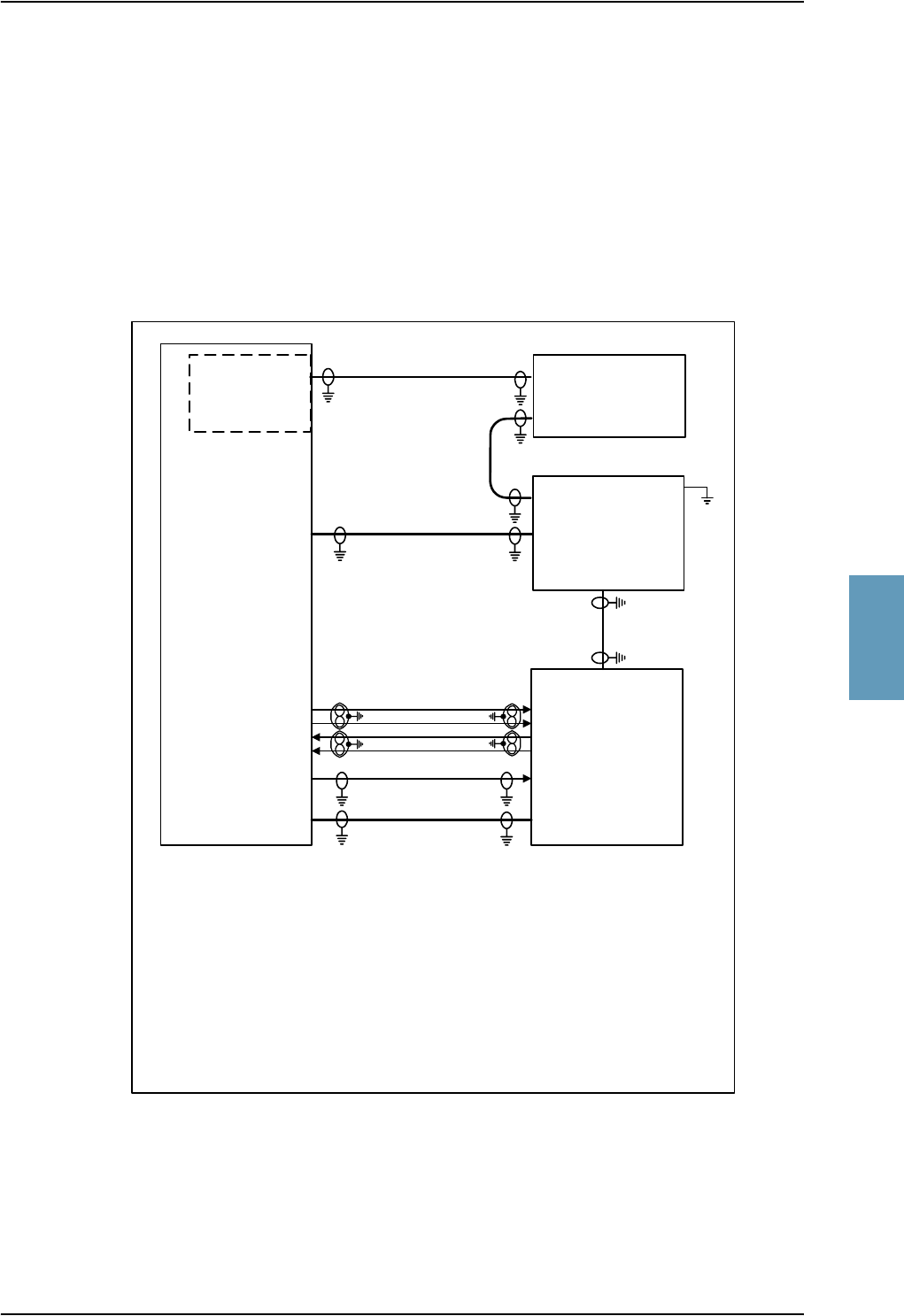
Electrical Installation and Wiring
TT98-113625-D Chapter 5: Installation 5-15
5555
Wiring of HGA-7000 Antenna
The following drawing shows the wiring for an Aero-HSD+ system using an
HGA-7000 antenna.
Note: For information on wiring an HGA-7000 Antenna when the TT-5038A
HSU is installed, see HGA-7000 Antenna with HSU on page 5-65.
Requirements to the cables are stated on the drawing and in the section Cable
Requirements, HGA-7000 Antenna on page 5-17.
Important! Remember to write down the cable losses. See Cable Losses on
page 5-14.
Figure 5-5: Wiring HGA-7000 Antenna and TT-5012A DLNA
TT-5035A
SDU
BP78
BP79
BP80
BP81
TP A2
HPA nON
BP57 BP6
TP2
BP27
BP28
BP25
BP26
TP A1
TT-5014A
HPA
[1] Coax, loss from cable W6 max. 12 dB
[2] Coax, loss from cable W5 max. 15 dB
[3] Coax, total loss from cable W3 and cable W4 max. 1.8 dB
[4] Coax, loss from cable W3 max. 0.3 dB
[5] Coax, loss from cable W7 max. 17 dB
[6] 16 AWG, max. 1 ft long, max. resistance 3 mΩ
HPA CONTROL
DATA / BITE
TP1
TT-5012A
DLNA
X3 TX
X1 RX
X2 Ant
HGA-7000
TP A4
[3], [4]
W5
W3
W6
J2 IF2
J1 IF1
Built-in
BSU
W7
[2]
[5]
[1]
GND
[6]
W4
[3]

Electrical Installation and Wiring
5-16 Chapter 5: Installation TT98-113625-D
The following list shows the pins in the Aero-HSD+ system used for connecting
the HGA-7000 antenna.
SDU pin Name/Description
TP A1 RF Rx input from TT-5012A DLNA/12V DC power to DLNA (Coax)
TP A2 RF Tx output to HPA (Coax)
TP A4 Antenna Modem Interface (Coax)
BP57 HPA remote nOn/Off output
BP78 HPA Control Output A, RS-422
BP79 HPA Control Output B, RS-422
BP80 HPA Data/BITE Input A, RS-422
BP81 HPA Data/BITE Input B, RS-422
Table 5-6: SDU Pins for HGA-7000 Antenna
HPA pin Name/Description
TP1 RF output to TT-5012A DLNA (Coax)
TP2 RF input from SDU (Coax)
BP6 Remote nOn/Off input from SDU
BP25 Tx Data/BITE Output A, RS-422, to SDU
BP26 Tx Data/BITE Output B, RS-422, to SDU
BP27 Rx Control Input A, RS-422, from SDU
BP28 Rx Control Input B, RS-422, from SDU
Table 5-7: HPA Pins for HGA-7000 Antenna
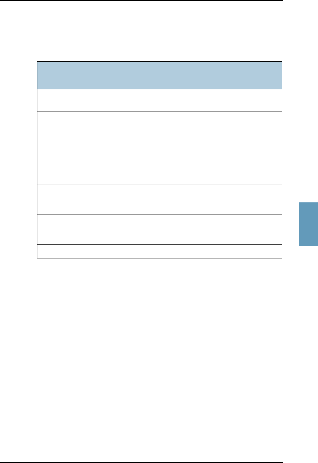
Electrical Installation and Wiring
TT98-113625-D Chapter 5: Installation 5-17
5555
Cable Requirements, HGA-7000 Antenna
The following list shows the cable requirements to the RF cables in the
Aero-HSD+ system when using an HGA-7000 antenna.
Cablea
a. The “W” cable numbers refer to the numbers stated on the wiring drawing in the section
Wiring of HGA-7000 Antenna on page 5-15.
Note: For recommended cable types, see Recommended RF Cables on
page 5-84.
Type
Min.
Cable Loss
@1.6 GHz
Max.
Cable Loss
@1.6 GHz
Other Requirements
W3
(DLNA-Antenna)
Coax 0 dB 0.3 dB
W4
(HPA-DLNA)
Coax 0 dB 1.8 dB - W3
W3 and W4 Coax 0 dB Total:
1.8 dB
W5
(TT-5012A DLNA
to SDU)
Coax 0 dB 15 dB
W6
(RF Tx output from
SDU to HPA)
Coax 0 dB 12 dB
W7
(Antenna modem
interface)
Coax 0 dB 17 dB
GND on DLNA - - - Resistance: Max. 3 mΩ
Table 5-8: Requirements to RF Cables, HGA-7000 Antenna

Electrical Installation and Wiring
5-18 Chapter 5: Installation TT98-113625-D
Wiring ARINC 741 Antenna Systems
The following drawing shows the wiring for an Aero-HSD+ system using the
AMT-50 antenna subsystem.
Note: For information on wiring an AMT-50 subsystem when the TT-5038A
HSU is installed, see AMT-50 Subsystem With HSU on page 5-69.
Requirements to the cables are stated on the drawing and in the section RF Cable
Requirements, AMT-50 Subsystem on page 5-20.
Important! Remember to write down the cable losses. See Cable Losses on
page 5-14.
Figure 5-6: Wiring AMT-50 Subsystem
TT-5035A
SDU
BP78
BP79
BP80
BP81
TP A2
HPA nON
BP57 BP6
TP2
BP27
BP28
BP25
BP26
TP A1
TT-5014A
HPA
HPA CONTROL
DATA / BITE
BP8
BP9
BP13
BP14
AMT-50
ACU
A B G H
TP1
AMT-50
DLNA
J3
J2
J1
AMT-50 Subsystem
[1] Coax, loss from cable W6 max. 12 dB
[2] Coax, loss from cable W5 min. 6 dB and max. 29 dB
[3] Coax, total loss from cable W3 and cable W4 max. 1.8 dB
[4] Coax, loss from cable W3 max. 0.3 dB
W5
W6
W4
AMT-50
Ant.
W3
[1]
[2]
[3]
[3] [4]
A429 Tx (HS)
A429 Rx (LS)

Electrical Installation and Wiring
TT98-113625-D Chapter 5: Installation 5-19
5555
The following list shows the pins in the Aero-HSD+ system used for connecting
the AMT-50 Subsystem.
SDU pin Name/Description
TP A1 RF Rx input from ARINC 741 DLNA (Coax)
TP A2 RF Tx output to HPA (Coax)
BP57 HPA remote nOn/Off output
BP78 HPA Control Output A, RS-422
BP79 HPA Control Output B, RS-422
BP80 HPA Data/BITE Input A, RS-422
BP81 HPA Data/BITE Input B, RS-422
Table 5-9: SDU Pins for AMT-50 Subsystem
HPA pin Name/Description
TP1 RF output to ARINC 741 DLNA (Coax)
TP2 RF input from SDU (Coax)
BP6 Remote nOn/Off input from SDU
BP8 A429 Tx A output to AMT-50 ACU
BP9 A429 Tx B output to AMT-50 ACU
BP13 A429 Rx1 A input from AMT-50 ACU
BP14 A429 Rx1 B input from AMT-50 ACU
BP25 Tx Data/BITE Output A, RS-422, to SDU
BP26 Tx Data/BITE Output B, RS-422, to SDU
BP27 Rx Control Input A, RS-422, from SDU
BP28 Rx Control Input B, RS-422, from SDU
Table 5-10: HPA Pins for AMT-50 Subsystem

Electrical Installation and Wiring
5-20 Chapter 5: Installation TT98-113625-D
RF Cable Requirements, AMT-50 Subsystem
The following list shows the cable requirements to the RF cables in the
Aero-HSD+ system when using an AMT-50 antenna subsystem.
Note: For recommended cable types, see Recommended RF Cables on
page 5-84.
Cable Requirements, ARINC 429
The cables for the ARINC 429 interfaces must be twisted and shielded and
conform to the standards for aeronautical use.
For recommended cable types, see Recommended Cables for ARINC 429 on
page 5-84.
Cablea
a. The “W” cable numbers refer to the numbers stated on the wiring drawing
in the section Wiring ARINC 741 Antenna Systems on page 5-18.
Type Min. Cable Loss
@1.6 GHz
Max. Cable
Loss@1.6 GHz
W3
(DLNA-Antenna)
Coax 0 dB 0.3 dB
W4
(HPA-DLNA)
Coax 0 dB 1.8 dB - W3
W3 and W4 Coax 0 dB Total: 1.8 dB
W5
(ARINC 741 DLNA
to SDU)
Coax 6 dB 29 dB
W6
(RF Tx output from
SDU to HPA)
Coax 0 dB 12 dB
Table 5-11: Requirements to RF Cables, AMT-50 Subsystem

Electrical Installation and Wiring
TT98-113625-D Chapter 5: Installation 5-21
5555
Wiring ARINC 741 Dual Side Panel Antenna System (Future Use)
The following drawing shows the wiring of an ARINC 741 dual side panel
antenna system.
Figure 5-7: Wiring ARINC 741 Dual Side Panel Antenna System
TT-5014A
HPA
A429 Rx2 A, BP15
A429 Rx2 B, BP16
A429 Tx A, BP10
A429 Tx B, BP11
HPA Mute 2 A, BP19
HPA Mute 2 B, BP20
BSU
(STBO)
A429 Rx1 A, BP13
A429 Rx1 B, BP14
A429 Tx A, BP8
A429 Tx B, BP9
HPA Mute 1 A, BP17
HPA Mute 1 B, BP18
BSU
(Port)
W
X
T
U
G
H
W
X
T
U
G
H
DLNA
(Port)
Ant
HPR
Tx Rx
DLNA
(STBO)
Ant
Tx Rx
RF Tx output, TP1
HGA
(Port)
HGA
(STBO)
TT-5035A
SDU
TPA1
Aero-HSD+ System
BP27
BP28
BP25
BP26
HPA nON
BP6 BP57
BP78
BP79
BP80
BP81
HPA CONTROL
Data/BITE
TP A2
TP2 RF Tx
RF Rx
Combiner
ARINC 741 Dual Side Panel Antenna System
[1] Coax, loss from cable W6: max. 12 dB
[2] Coax, total loss from each of the DLNAs to the SDU, including loss in
the Combiner: min. 6 dB and max. 29 dB
[3] Coax, total loss from HPA to each of the DLNAs, including loss in the
HPR: max. 1.5 dB, assuming that the total loss from DLNA to antenna is
0.3 dB.
W6
[1]
[2]
[2]
[2]
[3] [3]
[3]

Electrical Installation and Wiring
5-22 Chapter 5: Installation TT98-113625-D
Important! Remember to write down the cable losses. See Cable Losses on
page 5-14.
The following list shows the pins in the Aero-HSD+ system used for connecting a
Dual Side Panel antenna system.
HPA pin Name/Description
TP1 RF Tx output to HPR (Coax)
TP2 RF Tx input from SDU (Coax)
BP6 Remote nOn/Off input from SDU
BP8 A429 Tx A output to BSU (Port)
BP9 A429 Tx B output to BSU (Port)
BP10 A429 Tx A output to BSU (STBO)
BP11 A429 Tx B output to BSU (STBO)
BP13 A429 Rx1 A input from BSU (Port)
BP14 A429 Rx1 B input from BSU (Port)
BP15 A429 Rx2 A input from BSU (STBO)
BP16 A429 Rx2 B input from BSU (STBO)
BP17 HPA Mute 1 A input from BSU (Port)
BP18 HPA Mute 1 B input from BSU (Port)
BP19 HPA Mute 2 A input from BSU (STBO)
BP20 HPA Mute 2 B input from BSU (STBO)
BP25 Tx Data/BITE Output A, RS-422, to SDU
BP26 Tx Data/BITE Output B, RS-422, to SDU
BP27 Rx Control Input A, RS-422, from SDU
BP28 Rx Control Input B, RS-422, from SDU
Table 5-12: HPA Pins for Dual Side Panel Antenna System

Electrical Installation and Wiring
TT98-113625-D Chapter 5: Installation 5-23
5555
RF Cable Requirements, ARINC 741 Dual Side Panel Antenna System
The following list shows the cable requirements to the RF cables in the
Aero-HSD+ system when using an ARINC 741 Dual Side Panel Antenna System.
Note: For recommended cable types, see Recommended RF Cables on
page 5-84.
SDU pin Name/Description
TP A1 RF Rx input from Combiner (Coax)
TP A2 RF Tx output to HPA (Coax)
BP57 HPA remote nOn/Off output
BP78 HPA Control Output A, RS-422
BP79 HPA Control Output B, RS-422
BP80 HPA Data/BITE Input A, RS-422
BP81 HPA Data/BITE Input B, RS-422
Table 5-13: SDU Pins for Dual Side Panel Antenna System
Cablea
a. The “W” cable numbers refer to the numbers stated on the wiring drawing in
the section Wiring ARINC 741 Dual Side Panel Antenna System (Future
Use) on page 5-21.
Type Min. Cable Loss
@1.6 GHz
Max. Cable
Loss@1.6 GHz
RF Rx input from each
DLNA to SDU, incl.
loss in Combiner
Coax 6 dB 29 dB
RF Tx output from HPA
to DLNA, incl. loss in
HPR
Coax 0 dB 1.5 dB, assuming
that the loss from
DLNA to antenna
is 0.3 dB.
W6
(RF Tx output from
SDU to HPA)
Coax 0 dB 12 dB
Table 5-14: Requirements to RF Cables, ARINC 741 Dual Side Panel Antenna
System
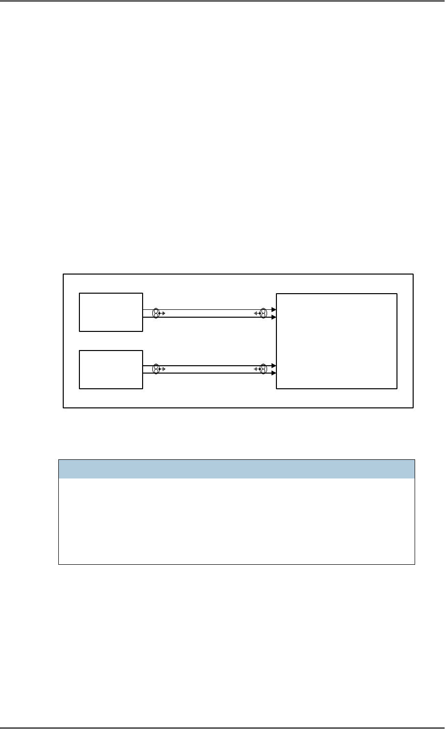
Electrical Installation and Wiring
5-24 Chapter 5: Installation TT98-113625-D
5.3.4 Wiring ARINC 429 Interfaces
AHRS/IRS
The SDU has two high or low speed ARINC 429 input interfaces for IRS #1 and
IRS #2. These inputs can also be used as Attitude and Heading Reference System
inputs (AHRS).
Important! ARINC specifies that when installing AHRS, a switch must be
installed, in order to be able to switch to Direct Gyro Mode when
the aircraft is on ground.
This is done to avoid magnetic interference, which can influence
the AHRS heading.
The following drawing shows the wiring of AHRS/IRS. Requirements to the
cables are stated in the section Cable Requirements, ARINC 429 on page 5-28.
The following list shows the pins used for AHRS or IRS:
Figure 5-8: Wiring AHRS/IRS
SDU Pin Name/Description
BP26 Data from primary IRS 429 A /Data from primary AHRS 429 A
BP27 Data from primary IRS 429 B /Data from primary AHRS 429 B
BP28 Data from secondary IRS 429 A /Data from secondary AHRS 429 A
BP29 Data from secondary IRS 429 B /Data from secondary AHRS 429 B
Table 5-15: SDU Pins for IRS and AHARS
AHRS / IRS
#2
ARINC 429 RX
AHRS / IRS
#1
ARINC 429 RX
TT-5035A
SDU
BP26
BP27
BP28
BP29

Electrical Installation and Wiring
TT98-113625-D Chapter 5: Installation 5-25
5555
When the system is configured with the HSD+ Configuration Program, the
Configuration Module will contain the information of:
• IRS or AHRS is installed.
• IRS/AHRS # 1 or #2 or both are installed.
Note: If #1 and #2 are both installed, they must be of the same type (IRS or
AHRS).
• ARINC 429 Speed (High or Low).
If IRS is used, the Antenna positioning data and Doppler correction are computed
from the IRS data alone, but if AHRS is used, the GPS must provide the SDU with
3D ECEF position and speed.
Note: AHRS can only be used with the HGA-7000 antenna, which contains a
built-in GPS antenna.
ARINC Data Format for IRS
The required ARINC data format for IRS is listed in the following table:
Label
(octal) Name Minimum
Update rate
310 Latitude 1 Hz
311 Longitude 1 Hz
312 Ground speed 1 Hz
313 Track angle 1 Hz
314 True heading 10 Hz
324 Pitch angle 10 Hz
325 Roll angle 10 Hz
336 Pitch rate 10 Hz
337 Roll rate 10 Hz
361 Altitude 1 Hz
Table 5-16: ARINC Data Format for IRS
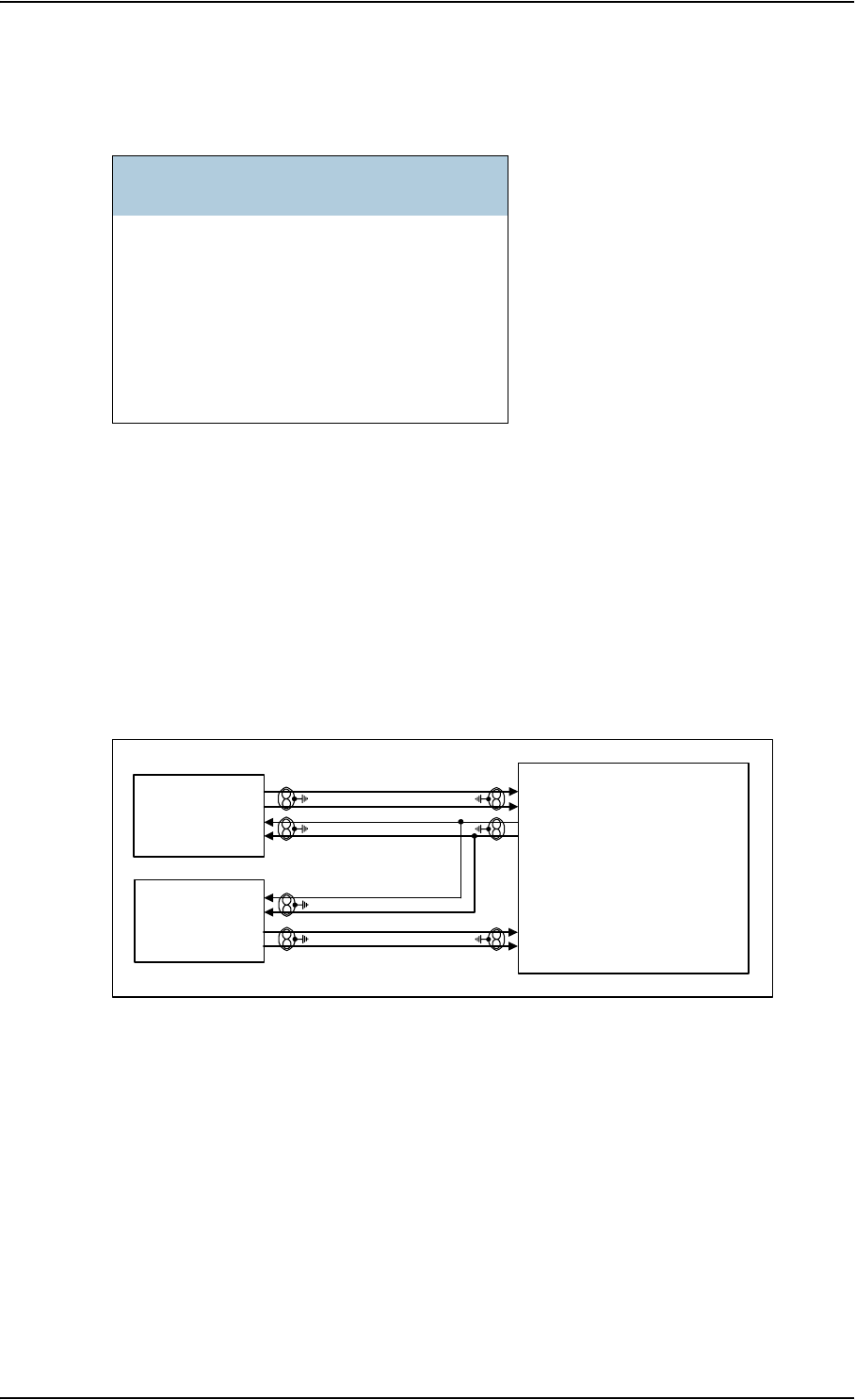
Electrical Installation and Wiring
5-26 Chapter 5: Installation TT98-113625-D
ARINC Data Format for AHRS
The required ARINC data format for AHRS is listed in the following table:
ACARS/CMU
The SDU has ARINC 429 interfaces for 2 high or low speed (HS/LS)
ACARS/CMU including one output port and 2 input ports.
The following drawing shows the wiring of ACARS/CMU. Requirements to the
cables are stated in the section Cable Requirements, ARINC 429 on page 5-28.
Label
(octal) Name Minimum
Update rate
320 Magnetic heading 10 Hz
324 Pitch angle 10 Hz
325 Roll angle 10 Hz
336 Pitch rate 10 Hz
337 Roll rate 10 Hz
Table 5-17: ARINC Data Format for AHRS
Figure 5-9: Wiring ACARS/CMU
ACARS / CMU
#1
HS/LS ARINC 429 TX
HS/LS ARINC 429 RX
ACARS / CMU
#2
HS/LS ARINC 429 RX
TT-5035A
SDU
BP44
BP45
BP40
BP41
BP42
BP43
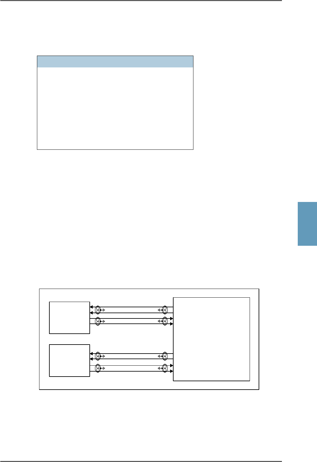
Electrical Installation and Wiring
TT98-113625-D Chapter 5: Installation 5-27
5555
The following list shows the pins used for an Airborne Communications
Addressing and Reporting System (ACARS) or a Communications Management
Unit (CMU):
The data speed can be configured to high or low (HS/LS), defined by the
Configuration Module.
CPDF (Future Use)
The SDU has interfaces prepared for two future Cabin Packet Data Functions.
The interfaces for CPDF #1 and #2 are high or low speed ARINC 429 input and
output.
The two ports are connected to separate serial ports.
The following drawing shows the wiring of CPDF. Requirements to the cables are
stated in the section Cable Requirements, ARINC 429 on page 5-28.
Note: CPDF #1 will not be available when the TT-5038A HSU is installed.
SDU Pin Name/Description
BP40 Data bus from ACARS/CMU #1 429 A
BP41 Data bus from ACARS/CMU #1 429 B
BP42 Data bus to ACARS/CMU #1 & #2 429 A
BP43 Data bus to ACARS/CMU #1 & #2 429 B
BP44 Data bus from ACARS/CMU #2 429 A
BP45 Data bus from ACARS/CMU #2 429 B
Table 5-18: SDU Pins for CMU
Figure 5-10: Wiring CPDF
CPDF #1
ARINC 429 RX
ARINC 429 TX
CPDF #2
ARINC 429 RX
ARINC 429 TX
TT-5035A
SDU
BP34
BP35
BP32
BP33
BP38
BP39
BP36
BP37
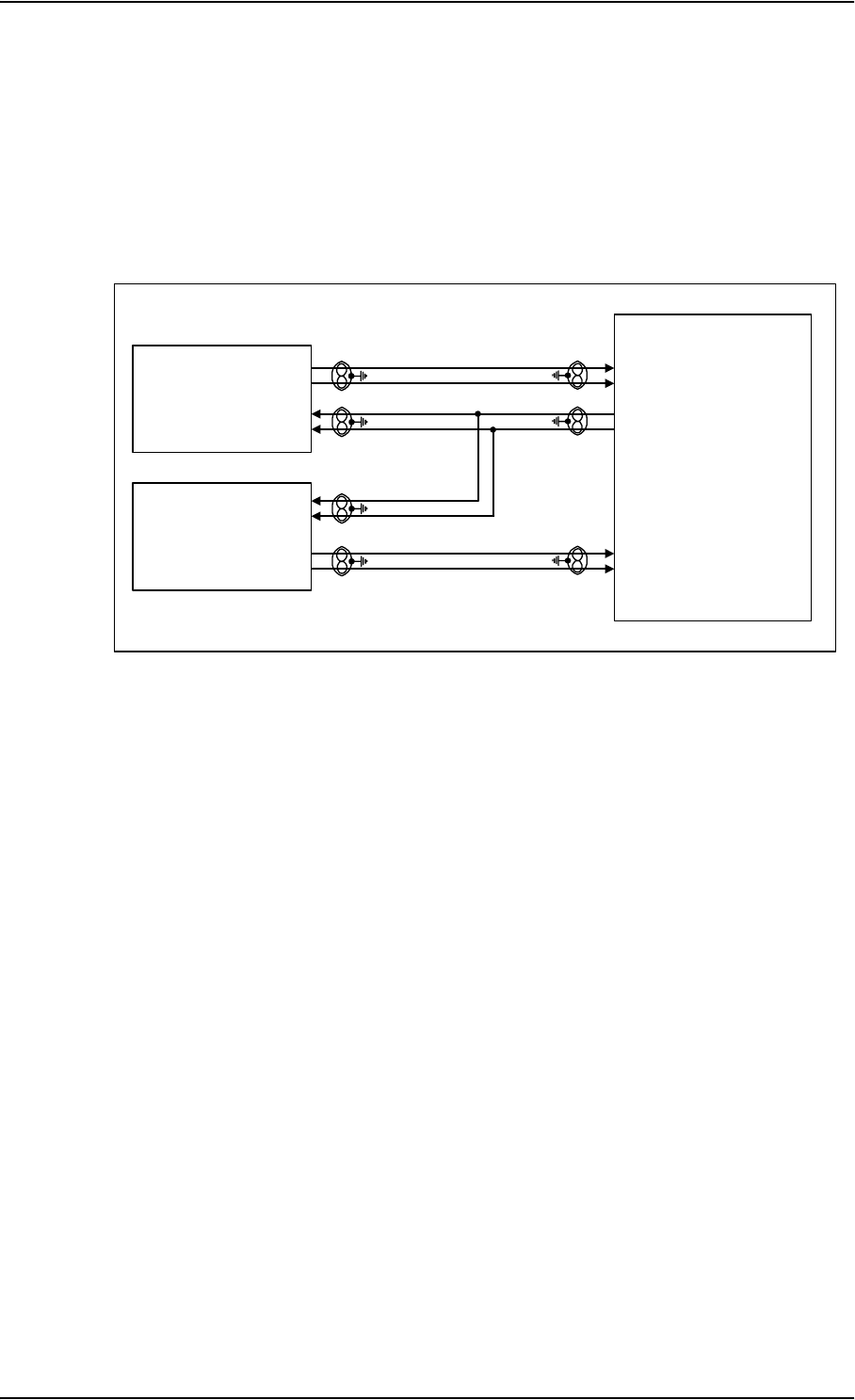
Electrical Installation and Wiring
5-28 Chapter 5: Installation TT98-113625-D
MCDU/FMS (Future Use)
The SDU has interfaces prepared for two future high or low speed ARINC 429
interfaces for communication with MCDU/FMS #1 and MCDU/FMS #2. One
common output and two inputs.
The following drawing shows the wiring of MCDU/FMS. Requirements to the
cables are stated in the section Cable Requirements, ARINC 429 on page 5-28.
The Configuration Module contains information if the FMS is installed, and which
data rate is used (high or low).
MCDU/FMS input #2 may also, in the future, be configured to AES ID input
(ARINC 429 ICAO Address). However, this is not yet implemented.
Cable Requirements, ARINC 429
The cables for the ARINC 429 interfaces must be twisted and shielded and
conform to the standards for aeronautical use.
For recommended cable types, see Recommended Cables for ARINC 429 on
page 5-84.
Figure 5-11: Wiring MCDU/FMS
TT-5035A
SDU
MCDU/FMS #1
HS/LS ARINC 429 RX
MCDU/FMS #2 /
AES ID
HS/LS ARINC 429 RX BP30
BP31
BP46
BP47
BP48
BP49
HS/LS ARINC 429 TX

Electrical Installation and Wiring
TT98-113625-D Chapter 5: Installation 5-29
5555
5.3.5 Wiring ICAO Address
Strapped ICAO Address
A unique aircraft identification code (ICAO address) must be assigned at
installation. The national authority of aeronautical identification coordinates
assignment of the code.
The ICAO address must be defined in the Configuration Module, using the
Aero-HSD+ Configuration Program.
The SDU obtains the ICAO address from the 24 bit discrete address (must be
hardware strapped using the 24 discrete inputs on the SDU).
The strapped ICAO address is compared to the ICAO address in the Configuration
Module. If they do not match, the Aero-HSD+ system suspends all RF
communication.
Other Sources for the ICAO Address (future use)
In the future, the SDU will be able to obtain the ICAO address from various
sources.
• the CMUs
• the AES_ID from the ARINC bus
• the 24 bit discrete address (hardware strapped)
The SDU will search for the ICAO address to ensure it is operating in the right
aircraft. When the SDU tries to retrieve the ICAO address, it will first check the
CMUs, then the AES_ID from the ARINC bus, and last the hardware strapped
ICAO address.
The found ICAO address is then compared to the ICAO address in the
Configuration Module. If they do not match, the Aero-HSD+ system will suspend
all RF communication.
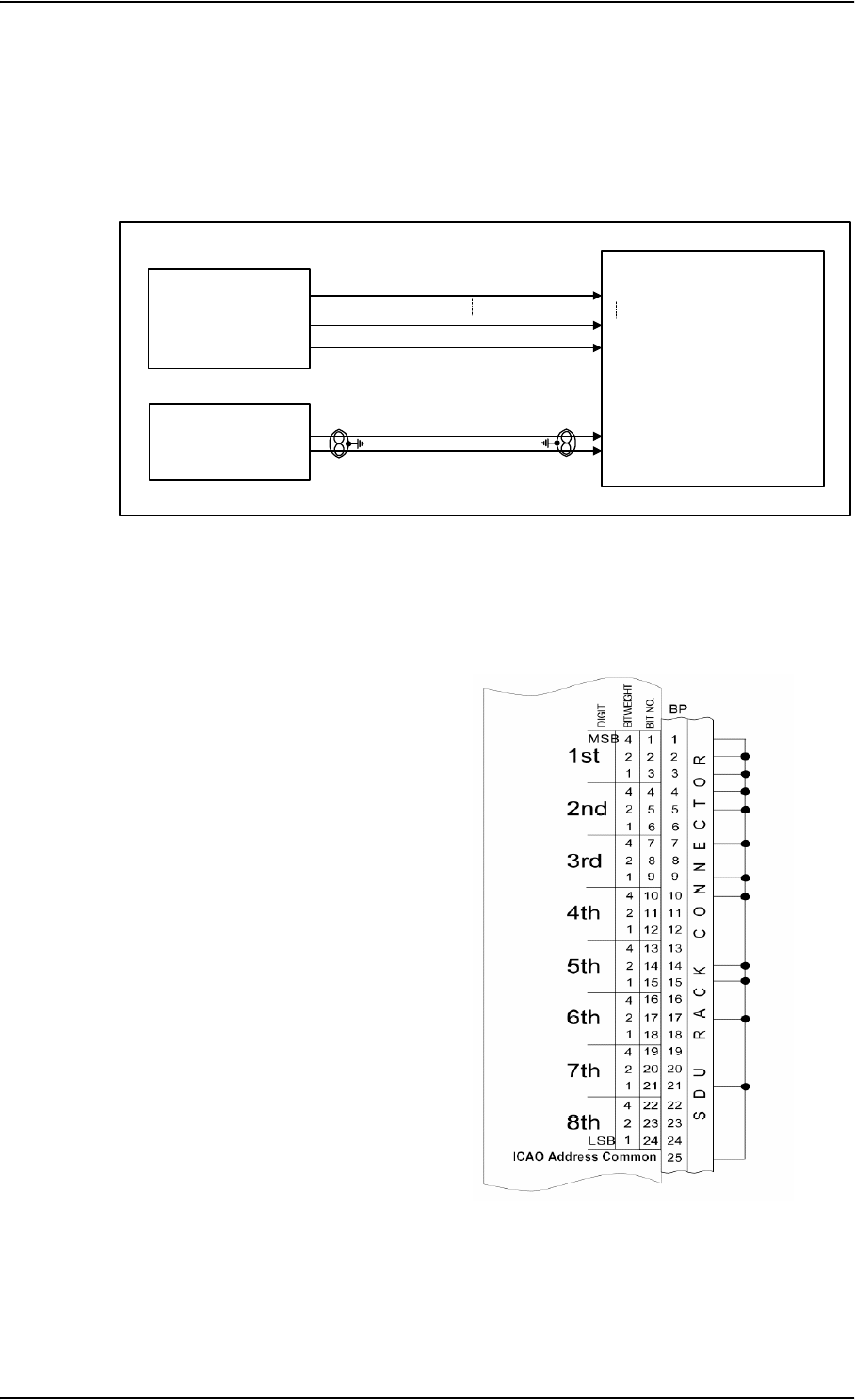
Electrical Installation and Wiring
5-30 Chapter 5: Installation TT98-113625-D
Wiring ICAO Address
The following drawing shows the wiring of the 24 bit discrete ICAO address and
the AES ID (future use). Requirements to the AES ID ARINC 429 cable are stated
in the section Cable Requirements, ARINC 429 on page 5-28.
Wiring 24 bit Discrete ICAO Address
The SDU has 24 discrete inputs used
to encode the 24-bit ICAO address, in
which the SDU is installed.
Each ICAO address consists of eight
digits, and each digit value is
determined by strapping 3 bits
(octal).
Note: The HSD+ Configuration
Program shows which pins
to connect if you type in the
wanted ICAO address in the
Config Module field in the
Identification window.
Figure 5-12: Wiring ICAO
TT-5035A
SDU
24 bit ICAO
address
discrete
ICAO ADDRESS BIT #1 (MSB)
ICAO ADDRESS BIT #24 (LSB)
ICAO ADDRESS COMMON
BP1
BP24
BP25
AES ID/
FMS
HS/LS ARINC 429 RX BP30
BP31
Figure 5-13: Example of Wiring the
Fictional ICAO Address 01234567
0
0
0
0
0
1
0
1
0
0
1
1
1
0
0
1
0
1
1
1
0
1
1
1
0
1
}
}
}
BIN DEC
2
}
}
}
}
}
3
4
5
6
7

Electrical Installation and Wiring
TT98-113625-D Chapter 5: Installation 5-31
5555
Do as follows to strap the ICAO address:
1. Leave pins assigned to the binary “one” state open (internal pull up).
Binary “one” (open circuit) is ≥100 kΩ.
2. Strap pins assigned to the binary “zero” state to BP25 (ICAO Address
Common) on the airframe side of the connector.
Binary “zero” (strapped to BP25) is ≤10 Ω.
3. Enter the ICAO address in the HSD+ Configuration Program.
If the aircraft uses a US N-type registration number, the HSD+ Configuration
Program can calculate the ICAO address from this number. Use the US N-
Type Calculator button in the Identification window of the HSD+CP.
When the system is powered, the SDU reads the strapped ICAO address from the
SDU rack connector and compares it to the ICAO address entered in the
Configuration Module. If the SDU does not detect or recognize the strapped ICAO
address, the Aero-HSD+ system will suspend all RF transmission until the error is
corrected.
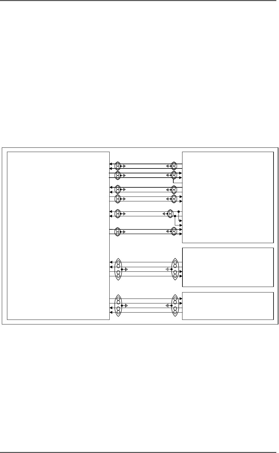
Electrical Installation and Wiring
5-32 Chapter 5: Installation TT98-113625-D
5.3.6 Wiring MPDS RS-422, MPDS Ethernet and ISDN
The SDU supports 56/64 kbit/s data rate and G4 fax on the High Speed Channel
connection. The interface can address up to 8 ISDN Phones. Note that the satellite
channel only supports one B channel and one Inmarsat signalling channel.
Note: For information on wiring a TT-5038A HSU to MPDS and ISDN, see
Wiring HSU to MPDS RS-232 , MPDS Ethernet and ISDN on
page 5-73.
The following drawing shows the wiring of the SDU to MPDS RS-422, MPDS
Ethernet and ISDN. Requirements to the cables are stated in the sections Cable
Requirements, MPDS RS-422 on page 5-33, Cable Requirements, ISDN on
page 5-35 and Cable Requirements, MPDS Ethernet 10BaseT on page 5-34.
Figure 5-14: Wiring MPDS RS-422, MPDS Ethernet and ISDN
MPDS
(DTE)
ISDN
(TE)
RJ45 Female Connector
ISDN TxP output, BP67
ISDN TxN output, BP68
ISDN RxP input, BP66
ISDN RxN input, BP69
MPDS
Ethernet 10BaseT
(DTE)
RJ45 Female Connector
MPDS DTR B input, BP102
MPDS DTR A input, BP103
MPDS DCD B output, BP104
MPDS DCD A output, BP105
RS-422
MPDS TXD-B input, BP58
MPDS TXD-A Input, BP59
MPDS RXD-B output, BP60
MPDS RXD-A output, BP61
MPDS RTS-B input, BP62
MPDS RTS-A input, BP63
MPDS CTS-B output, BP64
MPDS CTS-A output, BP65
TT-5035A
SDU
10BaseT Ethernet input, TPA3.1
10BaseT Ethernet input, TPA3.3
10BaseT Ethernet output, TPA3.2
10BaseT Ethernet output, TPA3.4
1 TxD+ output
2 TxD- output
3 RxD+ input
6 RxD- input
TxD-B output
TxD-A output
RxD-B input
RxD-A input
GND
RTS-B output
RTS-A output
CTS-B input
CTS-A input
DTR-B output
DTR-A output
DSR-B input
DSR-A input
DCD-B input
DCD-A input
3 Rx+ input
6 Rx- input
4 Tx+ output
5 Tx- output
DCE
NT1
DCE/Hub

Electrical Installation and Wiring
TT98-113625-D Chapter 5: Installation 5-33
5555
MPDS RS-422 Pins
RS-422 115.2 kbit/s Asynchronous RFC 1549 HDLC (www.ietf.org)
Configuration: DCE with hardware flow control (RTS and CTS as RS-422
signals).
The SDU supports an effective data rate of 64 kbit/s on the MPDS connection.
Cable Requirements, MPDS RS-422
The cable for the MPDS RS-422 interface must be a 100 Ω twisted and shielded
cable.
SDU pin Name Description
BP58 MPDS TxD B Input A RS-422 115.2 kbit/s
BP59 MPDS TxD A Input B RS-422 115.2 kbit/s
BP60 MPDS RxD B Output A RS-422 115.2 kbit/s
BP61 MPDS RxD A Output B RS-422 115.2 kbit/s
BP62 MPDS RTS B Input A RS-422 DCE hardware flow control
BP63 MPDS RTS A Input B RS-422 DCE hardware flow control
BP64 MPDS CTS B Output A RS-422 DCE hardware flow control
BP65 MPDS CTS A Output B RS-422 DCE hardware flow control
BP102 MPDS DTR B Input A RS-422 DCE hardware flow control
BP103 MPDS DTR A Input B RS-422 DCE hardware flow control
BP104 MPDS DCD B Output A RS-422 DCE hardware flow control
BP105 MPDS DCD A Output B RS-422 DCE hardware flow control
Table 5-19: SDU Pins for MPDS RS-422
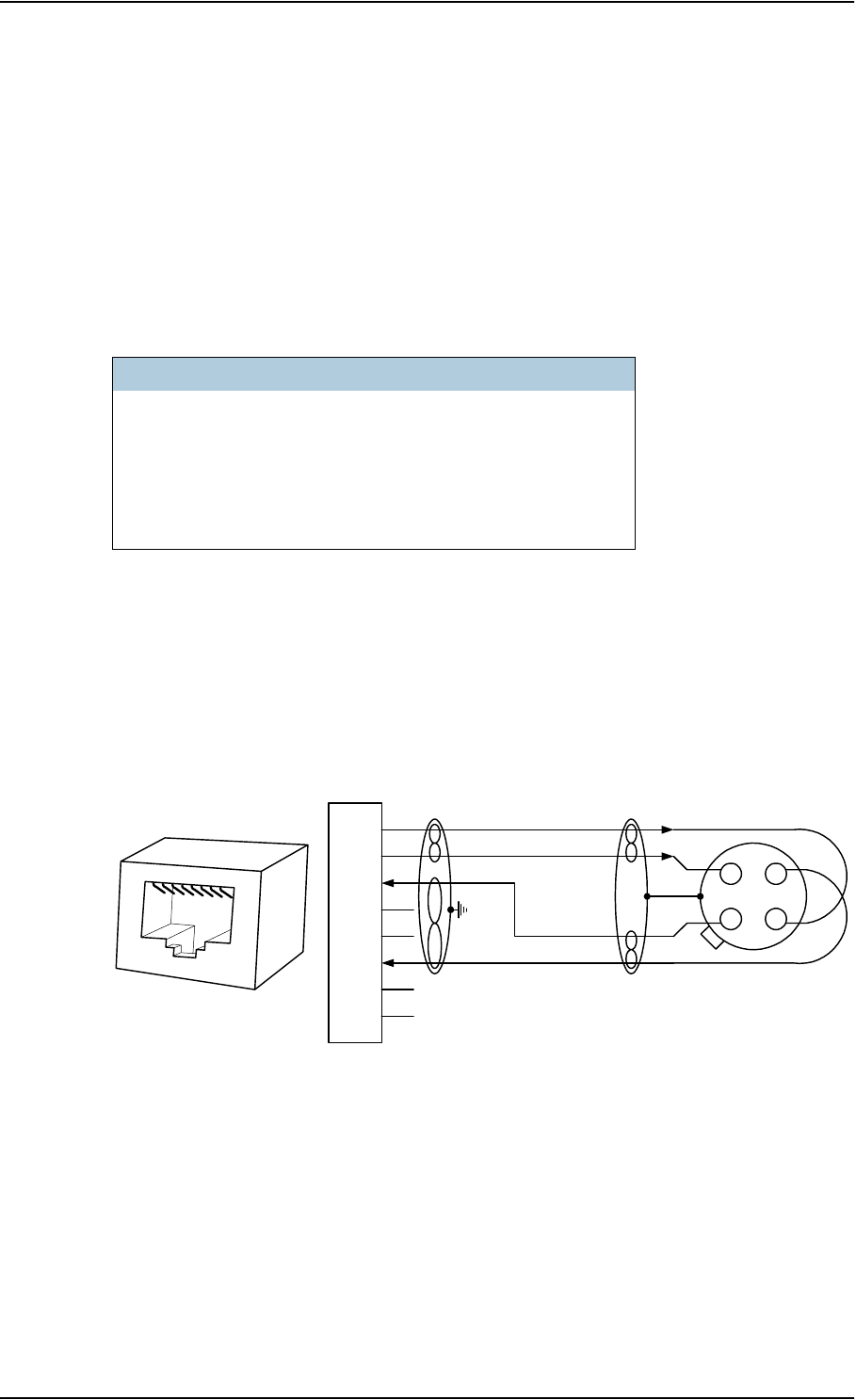
Electrical Installation and Wiring
5-34 Chapter 5: Installation TT98-113625-D
MPDS Ethernet 10BaseT Pins
The SDU Rear Connector Top Plug (TP) has a Quadrax connector insert in TP A3,
used for MPDS over Ethernet.
Important! Make sure the coding pin is inserted properly when you plug in the
Quadrax connector. It is possible to accidentally misplace the
coding pin, which could damage the connector or the SDU.
Refer to Figure 3-14: Contact Assembly: Quadrax Pin size 5 special: ITT
Cannon 244-0011-001 for information on assembly of the Quadrax connector.
The 10 Mbit/s Ethernet interface physical layer conforms to [1] (IEEE standard
802.3, Chapter 14: “Twisted Pair medium attachment unit”), except for the
connector type. To be compliant with [1], an RJ45 female connector must be used
for the user interface. The connector pin assignment must be according to [1] and
[2] as shown in Figure 5-15: MPDS Ethernet RJ45 Connector and Cable
Connection to SDU.
The SDU is defined as a DCE or a Hub i.e. TxD is input and RxD is output.
Cable Requirements, MPDS Ethernet 10BaseT
The cable for the MPDS Ethernet 10BaseT interface must be a 100 Ω 4-wire
twisted and shielded cable.
Recommended cable types are listed in Cables for MPDS Ethernet on SDU
(Quadrax Connector) on page 5-85.
SDU pin Name Description RJ45 PIN (F) Name
TP A3.1 Tx+ Input 1 TxD+
TP A3.2 Rx+ Output 3 RxD+
TP A3.3 Tx- Input 2 TxD-
TP A3.4 Rx- Output 6 RxD-
Table 5-20: SDU Pins for MPDS 10BaseT Ethernet
Figure 5-15: MPDS Ethernet RJ45 Connector and Cable Connection to SDU.
RJ45
female
1
2
3
4
5
6
7
8
TxD+ TX+ input
n.c.
TxD- TX- input
RxD+
RX+ output
n.c.
RxD- RX- output
n.c.
n.c.
SDU pin TP A3
to DTE
100Ω Quadrax twisted
and shielded pairs
SDU (DCE/Hub)
12345678
3
2
4
1
Shield
View: Cable insert
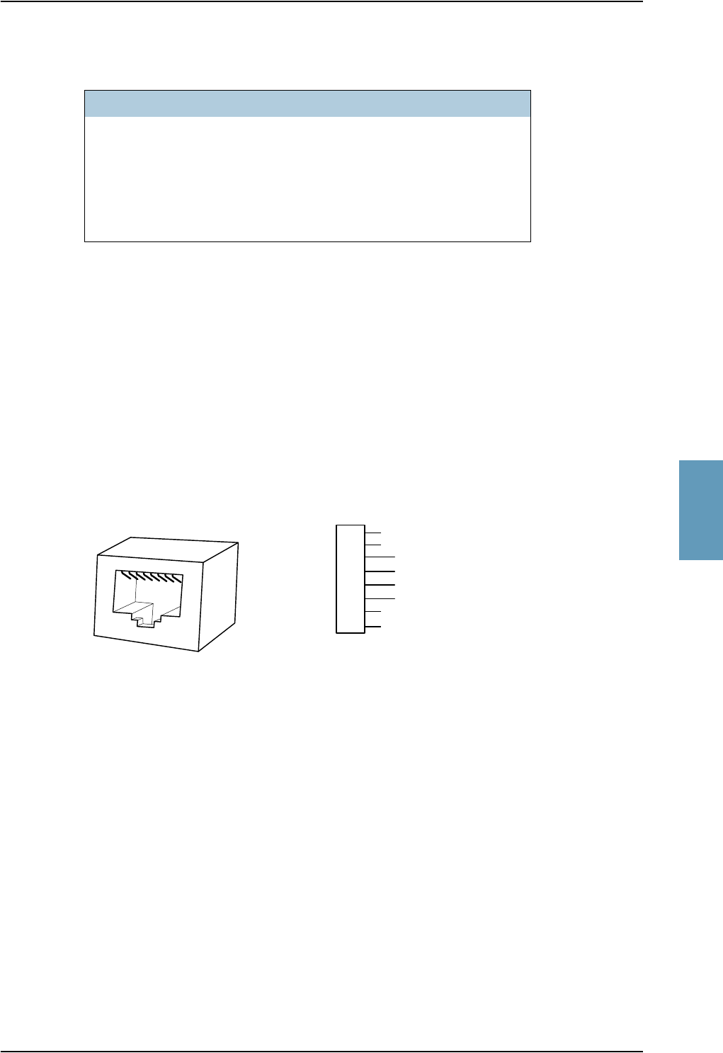
Electrical Installation and Wiring
TT98-113625-D Chapter 5: Installation 5-35
5555
ISDN Pins
The Euro ISDN S-bus interface on the SDU is configured as the network side of
the NT1 interface i.e. Rx is an input and Tx is an output. Please note that this
configuration of input and output differs from the configuration of the 10BaseT
Ethernet, RS-422 MPDS and RS-232 PC interface input/output.
An RJ-45 Female Connector must be connected to the four wire ISDN lines from
the SDU in order to be compliant with [2] (ISO8877 ISO/IEC 8877) and the ISDN
connector specification defined by [5] (ITU-T Recommendation I.420).
The SDU includes an internal 100 Ω termination resistor to support cable lengths
longer than 3 meters.
The Euro ISDN S-bus interface can power supply 4 ISDN phones but supports 8
phones (where 4 of them must have their own power supply). At power hold-up,
only power for one phone is available i.e. if more than one phone is connected, the
SDU may reset if an incoming call is received, or if more than one phone is off-
hook, during a power hold-up session.
Cable Requirements, ISDN
The cable for the ISDN interface must be a 100 Ω 4-wire shielded cable. The
conductors must be twisted in pairs.
SDU pin Name Description RJ45 PIN (F) Name
BP67 ISDN TxP Output 3 Rx+
BP68 ISDN TxN Output 6 Rx-
BP66 ISDN RxP Input 4 Tx+
BP69 ISDN RxN Input 5 Tx-
Table 5-21: SDU Pins for ISDN
Figure 5-16: ISDN RJ45 Connector
1
2
3
4
5
6
7
8
ISDN Rx+ Input
ISDN Tx+ Output
ISDN Tx- Output
ISDN Rx- Input
n.c.
n.c.
n.c.
n.c.
RJ45 (Female Connector)
RJ45
female
12345678

Electrical Installation and Wiring
5-36 Chapter 5: Installation TT98-113625-D
5.3.7 Wiring Telephone Systems
Built-In Private Branch Exchange (PBX)
The built-in PBX controls four 4-wire audio interfaces, two 2-wire POTS
interfaces and one ISDN interface.
4-Wire Audio
The 4-wire interfaces can be connected and configured to the 4-wire systems
listed below:
• TT-5020A/TT-5022A Handset/cradle system
• Up to two MagnaStar AIU (Analog Interface Units)
• Up to three 2.4 GHz Wireless handset base stations with WH-10 Satcom
interface
• Up to three WH-10 handsets
• Up to two Cockpit Voice Interfaces (for future use)
The four 4-wire handset interfaces are numbered handset interface #1 to #4.
• Handset interface #1 and #2 may interface to all systems mentioned above.
• Handset interface #3 may interface to all systems mentioned above except
Cockpit Voice.
• Handset interface #4 may only interface to TT-5020A/TT-5022A
Handset/cradle system.
The TT-5020A/TT-5022A Handset/cradle system is also used for configuration of
the handsets, phone book etc., and as a BITE and Satcom Status display. In order
to take advantage of these features, the SDU must be connected to at least one TT-
5020A/TT-5022A Handset/cradle system (typically handset #4).

Electrical Installation and Wiring
TT98-113625-D Chapter 5: Installation 5-37
5555
2-wire POTS
The 2-wire interfaces may be connected and configured to the 2-wire systems
listed below:
• TT-5021B / TT-5022B Cradle/Handset
• 2.4 GHz Wireless Phone with POTS interface
• Sigma7 phone with POTS interface
• FAX or Modem data with POTS interface
The maximum number of phones on each 2-wire POTS interface is:
Two TT-5021B / TT-5022B Cradle/Handsets or two Sigma7 phones, but only one
at the time should be active (off-hook) in order to avoid echo problems.
ISDN
The ISDN interface may be used with an ISDN phone and/or an ISDN data
modem. Only the ISDN phone is routed through the PBX, while the ISDN data
modem is routed directly to the RF High Speed Data channel. A maximum of 8
ISDN units (ISDN phones, ISDN fax or ISDN data modem) may be connected to
the ISDN interface, but only one unit may be active at the time.
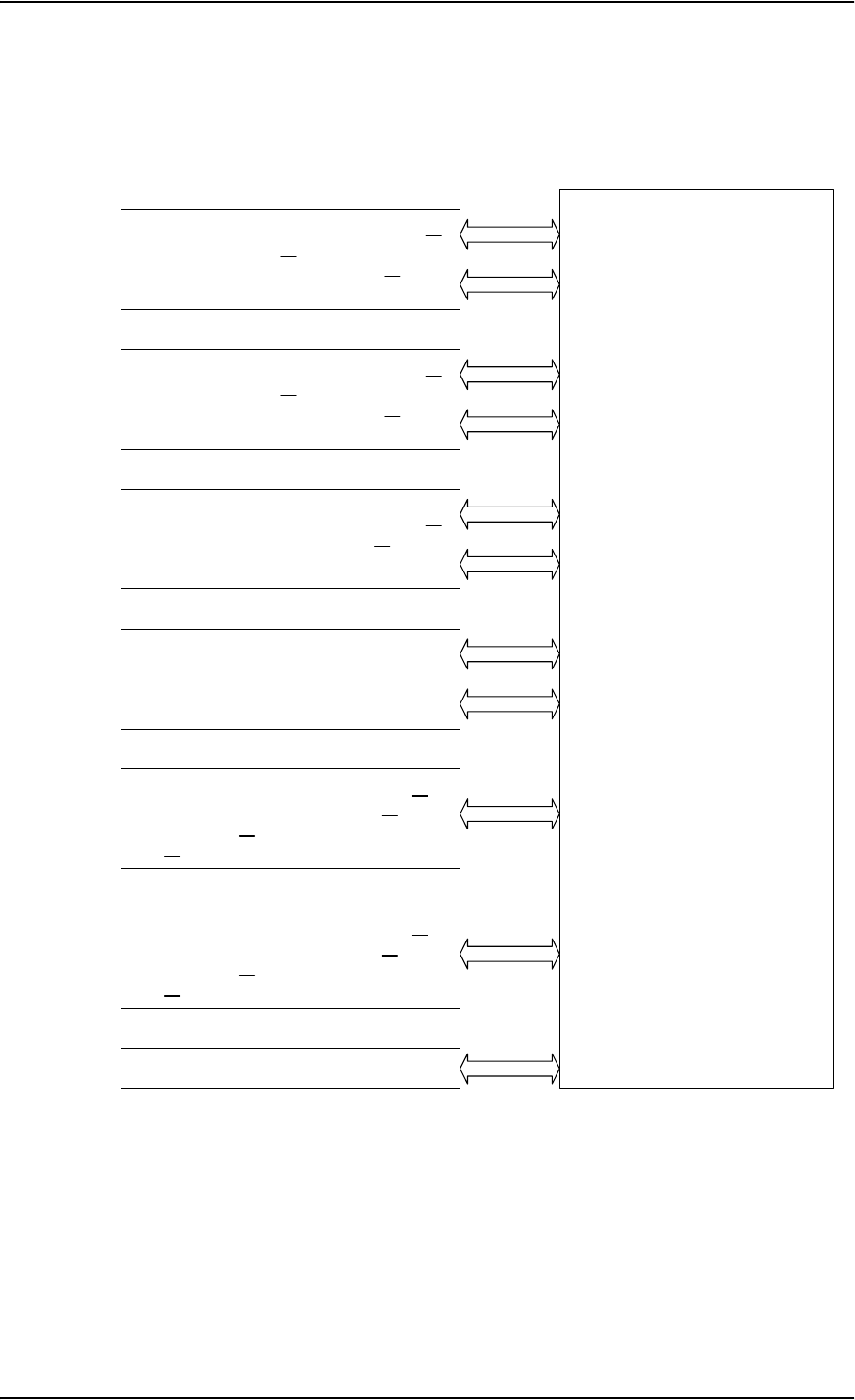
Electrical Installation and Wiring
5-38 Chapter 5: Installation TT98-113625-D
Configuration of Handset Interfaces
The following drawing shows the possible combinations of devices connected to
the handset interfaces.
Figure 5-17: Handset Interfaces, Possible Combinations of Connected Devices.
[1]: Maximum two MagnaStar AIUs may be installed. The preferred
installation of AIU #1 is to the four-wire Handset #1 interface, but AIU #1
may alternatively be connected to the four-wire Handset #3 interface
instead.
[2]: A Maximum of 8 ISDN units may be installed, and a maximum of two
ISDN units may be active (off hook) at the time. ISDN phones may be
routed to any four-wire, two-wire or RF channel, but ISDN modem data is
only routed to the High Speed RF channel.
TT-5035A SDU,
Private Branch Exchange (PBX)
4-wire audio
Control signals
TT-5020A / TT-5022A Handset System or
Magnastar
[1]
AIU #1 or
2.4 GHz Wireless Phone / WH-10 or
Cockpit Voice AMS #1 (future application)
Four-wire Handset interface #1
4-wire audio
Control signals
TT-5020A / TT-5022A Handset System or
Magnastar
[1]
AIU #2 or
2.4 GHz Wireless Phone / WH-10 or
Cockpit Voice AMS #2 (future application)
Four-wire Handset interface #2
4-wire audio
Control signals
TT-5020A / TT-5022A Handset System or
Alternative: Magnastar
[1]
AIU #1 or
2.4 GHz Wireless Phone / WH-10
Four-wire Handset interface #3
4-wire audio
Control signals
TT-5020A / TT-5022A Handset System
Four-wire Handset interface #4
2-wire POTS
TT-5021B / TT-5022B cradle/handset or
2.4 GHz Wireless Phone / POTS or
Sigma
7
Phone or
FAX or Modem
Two-wire Handset interface #5
2-wire POTS
TT-5021B / TT-5022B cradle/handset or
2.4 GHz Wireless Phone / POTS or
Sigma
7
Phone or
FAX or Modem
Two-wire Handset interface #6
ISDN
ISDN Phones / ISDN Modem
[2]
ISDN interface

Electrical Installation and Wiring
TT98-113625-D Chapter 5: Installation 5-39
5555
5.3.8 Wiring Thrane & Thrane Handset Systems
The following drawing shows the wiring of the TT-5622A/TT-5620A 4-wire
handsets and the TT-5621B/TT-5622B 2-wire handsets from Thrane & Thrane.
Figure 5-18: Wiring T&T Handset Systems
TT-5035A
SDU
TP4
TP3
NC
BP94 A
BP95 B
TP12 Hi
TP13 Lo
TP10 Hi
TP11 Lo
NC
BP96 A
BP97 B
TP17 Hi
TP18 Lo
TP15 Hi
TP16 Lo
NC
BP98 A
BP99 B
TP23 Hi
TP24 Lo
TP21 Hi
TP22 Lo
TT-5621B
CRADLE
BP100 A
BP101 B
TP28 Hi
TP29 Lo
TP26 Hi
TP27 Lo
DB15FDB15M
1
2
9
10
11
3
4
5
12
13
14
6
7
8
15
TT-5622A
CRADLE
1
2
9
10
11
3
4
5
12
13
14
6
7
8
15
TT-5620A
HANDSET
#1
1
2
9
10
11
3
4
5
12
13
14
6
7
8
15
TT-5622A
CRADLE
1
2
9
10
11
3
4
5
12
13
14
6
7
8
15
TT-5620A
HANDSET
#2
1
2
9
10
11
3
4
5
12
13
14
6
7
8
15
TT-5622A
CRADLE
1
2
9
10
11
3
4
5
12
13
14
6
7
8
15
TT-5620A
HANDSET
#3
Audio I/O
1
2
9
10
11
3
4
5
12
13
14
6
7
8
15
TT-5622A
CRADLE
1
2
9
10
11
3
4
5
12
13
14
6
7
8
15
TT-5620A
HANDSET
#4
Two-Wire fax
/ modem #5
Audio I/O
Two-Wire fax
/ modem #6
Audio I/O
Two-Wire fax
/ modem #5
Audio I/O
Two-Wire fax
/ modem #6
NC
TT-5621B
CRADLE
1
2
3
Two-Wire fax / modem #5
Two-Wire fax / modem #6
4-Wire Handset #1, RS-485 Data
Chassis Ground and Handset Power Return
1
2
3
1
2
3
1
2
3
DB9FDB9M
DB9M DB9F
+28 VDC / 600mA Handset Supply
Handset #1, Audio Out / Cockpit Voice Audio Out
Handset #1, Audio In / Cockpit Voice Audio In
4-Wire Handset #2, RS-485 Data
TT-5622B
HANDSET
#5
TT-5622B
HANDSET
#6
Handset #2, Audio Out / Cockpit Voice Audio Out
Handset #2, Audio In / Cockpit Voice Audio In
4-Wire Handset #3, RS-485 Data
Handset #3, Audio Out
Handset #3, Audio In
TP19
TP6
Tip
Ring Handset #5, 2-Wire Voice/Fax/Modem
TP8
TP7
Tip
Ring Handset #6, 2-Wire Voice/Fax/Modem
Handset #4, Audio Out
Handset #4, Audio In
4-Wire Handset #4, RS-485 Data
RJ11
RJ11
RJ11
RJ11
RJ11
RJ11
18" Pigtail
18" Pigtail
18" Pigtail
18" Pigtail
18" Pigtail
18" Pigtail
DB9F
DB9F
DB9F
DB9F
Note: 18" Pigtail with Sub-D connector is mounted on each cradle.
Wiring of Tip and Ring (SDU TP6-TP8 and TP19) is optional on the 4-Wire interfaces .

Electrical Installation and Wiring
5-40 Chapter 5: Installation TT98-113625-D
4-Wire Interfaces
The below list shows the pins used for the 4-wire interfaces on the SDU.
Pin no. Name/Description
TP10 Handset #1 Audio In Hi / (Future use: Cockpit Voice Audio #1 In Hi)
TP11 Handset #1 Audio In Lo / (Future use: Cockpit Voice Audio #1 In Lo)
TP12 Handset #1 Audio Out Hi / (Future use: Cockpit Voice Audio #1 Out Hi)
TP13 Handset #1 Audio Out Lo / (Future use: Cockpit Voice Audio #1 Out Lo)
BP94 Handset #1 RS-485 Data A
BP95 Handset #1 RS-485 Data B
TP15 Handset #2 Audio In Hi / (Future use: Cockpit Voice Audio #2 In Hi)
TP16 Handset #2 Audio In Lo / (Future use: Cockpit Voice Audio #2 In Lo)
TP17 Handset #2 Audio Out Hi / (Future use: Cockpit Voice Audio #2 Out Hi)
TP18 Handset #2 Audio Out Lo / (Future use: Cockpit Voice Audio #2 Out Lo)
BP96 Handset #2 RS-485 Data A
BP97 Handset #2 RS-485 Data B
TP21 Handset #3 Audio In Hi
TP22 Handset #3 Audio In Lo
TP23 Handset #3 Audio Out Hi
TP24 Handset #3 Audio Out Lo
BP98 Handset #3 RS-485 Data A
BP99 Handset #3 RS-485 Data B
TP26 Handset #4 Audio In Hi
TP27 Handset #4 Audio In Lo
TP28 Handset #4 Audio Out Hi
TP29 Handset #4 Audio Out Lo
BP100 Handset #4 RS-485 Data A
BP101 Handset #4 RS-485 Data B
TP4 +28 V DC / 600 mA Handset supply, remote On/Off control by TP5 (nON)
TP3 Handset Power Return
TP25 +12 V DC Spare Supply for test only - do not connect!
Table 5-22: SDU Pins for 4-Wire Interface

Electrical Installation and Wiring
TT98-113625-D Chapter 5: Installation 5-41
5555
The SDU has four 4-wire analog interfaces for the TT-5620A/ TT-5622A Thrane
& Thrane aeronautical handset system on the rear connector. The handsets use an
RS-485 data bus for on/off hook signalling, display control, keyboard control,
background light, etc.
Three of the 4-wire interfaces, #1, #2 and #3, can alternatively be used for
connection of MagnaStar or WH-10 phones. For information on possible
combinations, see Configuration of Handset Interfaces on page 5-38.
The handset interfaces must be configured in the HSD+ Configuration Program.
For information on wiring of MagnaStar, refer to Wiring MagnaStar Handsets
on page 5-42.
For information on wiring of WH-10 phones, refer to Wiring WH-10 Handsets
on page 5-45.
For information on wiring of 2.4GHz Cordless phones, refer to Wiring 2.4GHz
Cordless (4-Wire) Phone on page 5-48.
2-Wire Interfaces
The below list shows the pins used for the 2-wire interfaces of the SDU.
The SDU has two 2-wire voice/fax/modem POTS interfaces connected to the
built-in PBX. The interfaces comply with 2-wire 600 Ω standard US DTMF
telephones. The 2-wire interface is not galvanically isolated from the aircraft
frame, and galvanic isolation is required at the external 2-wire terminal.
Two TT-5621B 2-wire phones can be connected in parallel on each interface.
This interface is used for the TT-5621B/ TT-5622B Thrane & Thrane aeronautical
handset system, but may also be used for e.g. the Sigma7 or 2.4GHz Cordless
phones, or for a fax or a modem.
For information on wiring of Sigma7 phones, see Wiring Sigma7 (2-Wire)
Handsets on page 5-52.
For information on wiring of 2.4GHz Cordless phones, see Wiring 2.4GHz
Cordless (2-Wire) Phone on page 5-53.
Pin no. (X2) Name/Description
TP6 2-Wire Voice/Fax/Modem #1 (Ring)
TP7 2-Wire Voice/Fax/Modem #2 (Ring)
TP8 2-Wire Voice/Fax/Modem #2(Tip)
TP19 2-Wire Voice/Fax/Modem #1 (Tip)
Table 5-23: SDU Pins for 2-Wire Interface

Electrical Installation and Wiring
5-42 Chapter 5: Installation TT98-113625-D
5.3.9 Wiring MagnaStar Handsets
The following drawing shows the wiring of the MagnaStar handsets.
Figure 5-19: Wiring MagnaStar Interface
TT-5035A
SDU
BP83
BP84
BP82
BP54
TP12
TP13
TP10
TP11
BP86
BP87
BP85
TP17
TP18
TP15
TP16
STATUS A (Ringer Output A2)
MagnaStar
AIU 1
(Connector J3)
6
7
21
22
10
11
13
25
15
24
MagnaStar
AIU 2
(Connector J3)
6
7
21
22
10
11
13
25
14
24
STATUS B (Ringer Output B2)
CHOOKSW (Hook switch #2)
SATCOM Service Unavailable
HANDSET #2 AUDIO OUT (4W)
HANDSET #2 AUDIO IN (4W)
STATUS A (Ringer Output A1)
STATUS B (Ringer Output B1)
CHOOKSW (Hook switch #1)
SATCOM Service Unavailable
HANDSET #1 AUDIO OUT (4W)
HANDSET #1 AUDIO IN (4W)
NOTE
This wiring diagram only addresses the MagnaStar interfaces to the TT-5035A SDU.
For any additional MagnaStar installation information refer to the applicable MagnaStar installation
documentation.
SATCOM1_CONFIG
SATCOM2_CONFIG
Handset Interface #1
Handset Interface #2
BP89
BP90
BP55
TP23
TP24
TP21
TP22
TP20
STATUS A (Ringer Output A3)
Alternative
Position for
MagnaStar
AIU 1
(Connector J3)
6
7
21
22
10
11
13
25
15
24
STATUS B (Ringer Output B3)
CHOOKSW (Hook switch #3)
SATCOM Service Unavailable
HANDSET #3 AUDIO OUT (4W)
HANDSET #3 AUDIO IN (4W)
GND (Handset Return)
SATCOM1_CONFIG
Handset Interface #3

Electrical Installation and Wiring
TT98-113625-D Chapter 5: Installation 5-43
5555
The below list shows the pins used for the MagnaStar interfaces on the SDU.
Pin no. Name/Description
TP10 Handset #1 Audio In Hi / (Future use: Cockpit Voice Audio #1 In Hi)
TP11 Handset #1 Audio In Lo / (Future use: Cockpit Voice Audio #1 In Lo)
TP12 Handset #1 Audio Out Hi / (Future use: Cockpit Voice Audio #1 Out Hi)
TP13 Handset #1 Audio Out Lo / (Future use: Cockpit Voice Audio #1 Out Lo)
BP54 MagnaStar: Satcom Service Unavailable. Discrete output.
BP82 WH-10/MagnaStar Hook Switch #1
(Future use: CP Voice Call Cancel Input #1). Discrete input.
BP83 WH-10/MagnaStar Ringer Output A1
(Future use: CP Voice Mic On Input #1). Discrete I/O.
BP84 WH-10/MagnaStar Ringer Output B1
(Future use: CP Voice Call Light Output #1). Discrete output.
TP15 Handset #2 Audio In Hi / (Future use: Cockpit Voice Audio #2 In Hi)
TP16 Handset #2 Audio In Lo / (Future use: Cockpit Voice Audio #2 In Lo)
TP17 Handset #2 Audio Out Hi / (Future use: Cockpit Voice Audio #2 Out Hi)
TP18 Handset #2 Audio Out Lo / (Future use: Cockpit Voice Audio #2 Out Lo)
BP85 WH-10/MagnaStar Hook Switch #2
(Future use: CP Voice Call Cancel Input #2). Discrete input.
BP86 WH-10/MagnaStar Ringer Output A2
(Future use: CP Voice Mic On Input #2). Discrete I/O.
BP87 WH-10/MagnaStar Ringer Output B2
(Future use: CP Voice Call Light Output #2). Discrete output.
TP21 Handset #3 Audio In Hi
TP22 Handset #3 Audio In Lo
TP23 Handset #3 Audio Out Hi
TP24 Handset #3 Audio Out Lo
BP55 WH-10/MagnaStar: Hook switch #3
BP89 WH-10/MagnaStar Ringer Output A3
or Service Available Annunciator. Discrete I/O.
BP90 WH-10/MagnaStar Ringer Output B3
TP20 AGND
Table 5-24: SDU Pins for MagnaStar Interface

Electrical Installation and Wiring
5-44 Chapter 5: Installation TT98-113625-D
One or two MagnaStar Analog Interface Units (AIUs) can be connected to the
Aero-HSD+ system, using the handset interfaces #1, #2 or #3.
If two MagnaStar AIUs are connected, the pins “SATCOM1_CONFIG” and
“SATCOM2_CONFIG” are used to signal which channel is used (connect pin 15
on AIU1 to GND and pin 14 on AIU2 to GND).
Note: The 4-wire handset system #1, #2 and #3 interfaces are used for either the
4-Wire Handset System, MagnaStar, 2.4GHz Cordless or WH-10
phones, as configurations share the same interface. For information on
possible combinations, see Configuration of Handset Interfaces on
page 5-38.
The handset interfaces must be configured in the HSD+ Configuration
Program
For further information on the handset interfaces, see 4-Wire Interfaces on
page 5-40.
Apart from the handset interfaces, the SDU has a number of discrete
inputs/outputs used for MagnaStar/WH-10 systems. For information on these
interfaces, see Discretes for MagnaStar/WH-10 Handset Systems on page 5-51.

Electrical Installation and Wiring
TT98-113625-D Chapter 5: Installation 5-45
5555
5.3.10 Wiring WH-10 Handsets
The following drawing shows the wiring of WH-10 handsets.
Figure 5-20: Wiring WH-10 Handsets
H. RINGER B1
A
B
E
L
K
U
R
J
M
WH10
Handset 1
+ 28V DC Handset Supply
Chassis Ground and Handset Power Return
HANDSET HOOK Switch #1
H. RINGER A1
4-W LINE (TX)
H. RINGER B2
A
B
E
L
K
U
R
J
M
WH10
Handset 2
HANDSET HOOK Switch #2
H. RINGER A2
H. RINGER B3
A
B
E
L
K
U
R
J
M
WH10
Handset 3
HANDSET HOOK Switch #3
H. RINGER A3
4-W LINE (TX)
4-W LINE (RX)
4-W LINE (RX)
TP4
TP3
BP82
BP83
BP84
TP12
TP13
TP10
TP11
TT-5035A
SDU
BP85
BP86
BP87
TP17
TP18
TP15
TP16
BP55
BP89
BP90
TP23
TP24
TP21
TP22
4-W LINE (RX)
4-W LINE (TX)
4-W LINE (TX)
4-W LINE (RX)
4-W LINE (TX)
4-W LINE (TX)
4-W LINE (RX)
4-W LINE (RX)
Handset
Interface #1
Handset
Interface #2
Handset
Interface #3
Note: + 28 V and Chassis Ground must be connected as close as possible to TP3/TP4

Electrical Installation and Wiring
5-46 Chapter 5: Installation TT98-113625-D
The below list shows the pins used for the WH-10 interfaces on the SDU.
Pin no. Name/Description
TP3 Chassis Ground and Handset Power Return
TP4 +28 V DC/600 mA Handset Supply
TP10 Handset #1 Audio In Hi / (Future use: Cockpit Voice Audio #1 In Hi)
TP11 Handset #1 Audio In Lo / (Future use: Cockpit Voice Audio #1 In Lo)
TP12 Handset #1 Audio Out Hi / (Future use: Cockpit Voice Audio #1 Out Hi)
TP13 Handset #1 Audio Out Lo / (Future use: Cockpit Voice Audio #1 Out Lo)
BP82 WH-10/MagnaStar Hook Switch #1
(Future use: CP Voice Call Cancel Input #1). Discrete input.
BP83 WH-10/MagnaStar Ringer Output A1
(Future use: CP Voice Mic On Input #1). Discrete I/O.
BP84 WH-10/MagnaStar Ringer Output B1
(Future use: CP Voice Call Light Output #1). Discrete output.
TP15 Handset #2 Audio In Hi / (Future use: Cockpit Voice Audio #2 In Hi)
TP16 Handset #2 Audio In Lo / (Future use: Cockpit Voice Audio #2 In Lo)
TP17 Handset #2 Audio Out Hi / (Future use: Cockpit Voice Audio #2 Out Hi)
TP18 Handset #2 Audio Out Lo / (Future use: Cockpit Voice Audio #2 Out Lo)
BP85 WH-10/MagnaStar Hook Switch #2
(Future use: CP Voice Call Cancel Input #2). Discrete input.
BP86 WH-10/MagnaStar Ringer Output A2
(Future use: CP Voice Mic On Input #2). Discrete I/O.
BP87 WH-10/MagnaStar Ringer Output B2
(Future use: CP Voice Call Light Output #2). Discrete output.
TP21 Handset #3 Audio In Hi
TP22 Handset #3 Audio In Lo
TP23 Handset #3 Audio Out Hi
TP24 Handset #3 Audio Out Lo
BP55 WH-10/MagnaStar: Hook switch #3
BP89 WH-10/MagnaStar Ringer Output A3
or Service Available Annunciator. Discrete I/O.
BP90 WH-10/MagnaStar Ringer Output B3
Table 5-25: SDU Pins for WH-10 Interface

Electrical Installation and Wiring
TT98-113625-D Chapter 5: Installation 5-47
5555
Up to three WH-10 systems can be connected to the Aero-HSD+ system, using the
interfaces #1, #2 or #3.
Note: The 4-wire handset system #1, #2 and #3 interfaces are used for either the
4-Wire Handset System, MagnaStar, 2.4GHz Cordless or WH-10
phones, as configurations share the same interface. For information on
possible combinations, see Configuration of Handset Interfaces on
page 5-38.
The handset interfaces must be configured in the HSD+ Configuration
Program.
For further information on the interfaces, see 4-Wire Interfaces on page 5-40.
Apart from the handset interfaces, the SDU has a number of discrete
inputs/outputs used for MagnaStar/WH-10 systems. For information on these
interfaces, see Discretes for MagnaStar/WH-10 Handset Systems on page 5-51.
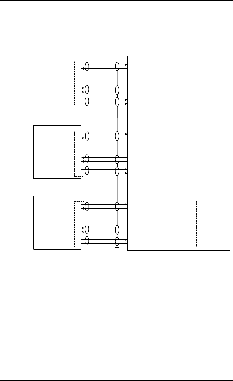
Electrical Installation and Wiring
5-48 Chapter 5: Installation TT98-113625-D
5.3.11 Wiring 2.4GHz Cordless (4-Wire) Phone
The following drawing shows the wiring of 2.4GHz Cordless 4-wire handsets.
Note: The power for the 2.4GHz Cordless base unit must be supplied from an
external power supply. See the 2.4GHz Cordless manual for details.
Figure 5-21: Wiring 2.4GHz Cordless 4-Wire Handsets
7
6
2
3
4
5
2.4GHz
Cordless
Base Unit
Tx Lo
BP82
BP83
TP12
TP13
TP10
TP11
TT-5035A
SDU
BP85
BP86
TP17
TP18
TP15
TP16
BP55
BP89
TP23
TP24
TP21
TP22
Tx Hi
Handset
Interface #1
2.4GHz
Cordless
Base Unit
2.4GHz
Cordless
Base Unit
J2
7
6
2
3
4
5
J2
7
6
2
3
4
5
J2
Rx Hi
Rx Lo
Ring in
Hook Switch
Tx Lo
Tx Hi
Rx Hi
Rx Lo
Ring in
Hook Switch
Tx Lo
Tx Hi
Rx Hi
Rx Lo
Ring in
Hook Switch
WH10/MagnaStar Hook Switch #1
WH10/MagnaStar Ringer Output A1
Handset #1 Audio Out Hi
Handset #1 Audio Out Lo
Handset #1 Audio In Hi
Handset #1 Audio In Lo
WH10/MagnaStar Hook Switch #2
WH10/MagnaStar Ringer Output A2
Handset #2 Audio Out Hi
Handset #2 Audio Out Lo
Handset #2 Audio In Hi
Handset #2 Audio In Lo
Handset #1 Audio Out Hi
Handset #1 Audio Out Lo
Handset #1 Audio In Hi
Handset #1 Audio In Lo
WH10/MagnaStar Hook Switch #3
WH10/MagnaStar Ringer Output A3
Handset
Interface #2
Handset
Interface #3

Electrical Installation and Wiring
TT98-113625-D Chapter 5: Installation 5-49
5555
The below list shows the pins used for the 2.4GHz Cordless (WH-10) interfaces
on the SDU.
Pin no. Name/Description
TP10 Handset #1 Audio In Hi / (Future use: Cockpit Voice Audio #1 In Hi)
TP11 Handset #1 Audio In Lo / (Future use: Cockpit Voice Audio #1 In Lo)
TP12 Handset #1 Audio Out Hi / (Future use: Cockpit Voice Audio #1 Out Hi)
TP13 Handset #1 Audio Out Lo / (Future use: Cockpit Voice Audio #1 Out Lo)
BP82 WH-10/MagnaStar Hook Switch #1
(Future use: CP Voice Call Cancel Input #1). Discrete input.
BP83 WH-10/MagnaStar Ringer Output A1
(Future use: CP Voice Mic On Input #1). Discrete I/O.
TP15 Handset #2 Audio In Hi / (Future use: Cockpit Voice Audio #2 In Hi)
TP16 Handset #2 Audio In Lo / (Future use: Cockpit Voice Audio #2 In Lo)
TP17 Handset #2 Audio Out Hi / (Future use: Cockpit Voice Audio #2 Out Hi)
TP18 Handset #2 Audio Out Lo / (Future use: Cockpit Voice Audio #2 Out Lo)
BP85 WH-10/MagnaStar Hook Switch #2
(Future use: CP Voice Call Cancel Input #2). Discrete input.
BP86 WH-10/MagnaStar Ringer Output A2
(Future use: CP Voice Mic On Input #2). Discrete I/O.
TP21 Handset #3 Audio In Hi
TP22 Handset #3 Audio In Lo
TP23 Handset #3 Audio Out Hi
TP24 Handset #3 Audio Out Lo
BP55 WH-10/MagnaStar: Hook switch #3
BP89 WH-10/MagnaStar Ringer Output A3
or Service Available Annunciator. Discrete I/O.
Table 5-26: SDU Pins for 2.4GHz Cordless (WH-10) Interface

Electrical Installation and Wiring
5-50 Chapter 5: Installation TT98-113625-D
Up to three 2.4GHz Cordless Handsets can be connected to the Aero-HSD+
system, using the interfaces #1, #2 or #3.
Note: The 4-wire handset system #1, #2 and #3 interfaces are used for either
the 4-Wire Handset System, MagnaStar, 2.4GHz Cordless or WH-10
phones, as configurations share the same interface. For information on
possible combinations, see Configuration of Handset Interfaces on
page 5-38. Handset interface #4 can only be used for the 4-Wire Handset
System.
The handset interfaces must be configured in the HSD+ Configuration
Program.
For further information on the interfaces, see 4-Wire Interfaces on page 5-40.
Apart from the handset interfaces, the SDU has a number of discrete
inputs/outputs used for MagnaStar/WH-10 systems. For information on these
interfaces, see Discretes for MagnaStar/WH-10 Handset Systems on page 5-51.

Electrical Installation and Wiring
TT98-113625-D Chapter 5: Installation 5-51
5555
5.3.12 Discretes for MagnaStar/WH-10 Handset Systems
The below list shows the discretes used for the MagnaStar/WH-10 interfaces on
the SDU. For more information on the discrete types, refer to Description of the
Discrete Types on page 5-57.
Pin no. Name/Description Discrete Type
BP54 MagnaStar: Satcom Service Unavailable Lamp Driver output
BP55 WH-10/MagnaStar: Hook switch #3 WOW input
BP82 WH-10/MagnaStar Hook Switch #1
(Future use: CP Voice Call Cancel Input #1)
WOW input
BP83 WH-10/MagnaStar Ringer Output A1
(Future use: CP Voice Mic On Input #1).
Discrete I/O.
Lamp Driver output
(Future use: Mic On Input)
BP84 WH-10/MagnaStar Ringer Output B1
(Future use: CP Voice Call Light Output #1).
Discrete output.
Lamp Driver output
(Future use: Call Light
output)
BP85 WH-10/MagnaStar Hook Switch #2
(Future use: CP Voice Call Cancel Input #2)
WOW input
BP86 WH-10/MagnaStar Ringer Output A2
(Future use: CP Voice Mic On Input #2).
Discrete I/O.
Lamp Driver output
(Future use: Mic On Input)
BP87 WH-10/MagnaStar Ringer Output B2
(Future use: CP Voice Call Light Output #2).
Discrete output.
Lamp Driver output
(Future use: Call Light
output)
BP89 WH-10/MagnaStar Ringer Output A3
or Service Available Annunciator. Discrete I/O.
Lamp Driver output
BP90 WH-10/MagnaStar Ringer Output B3 Lamp Driver output
Table 5-27: SDU Discretes for MagnaStar/WH-10 Systems
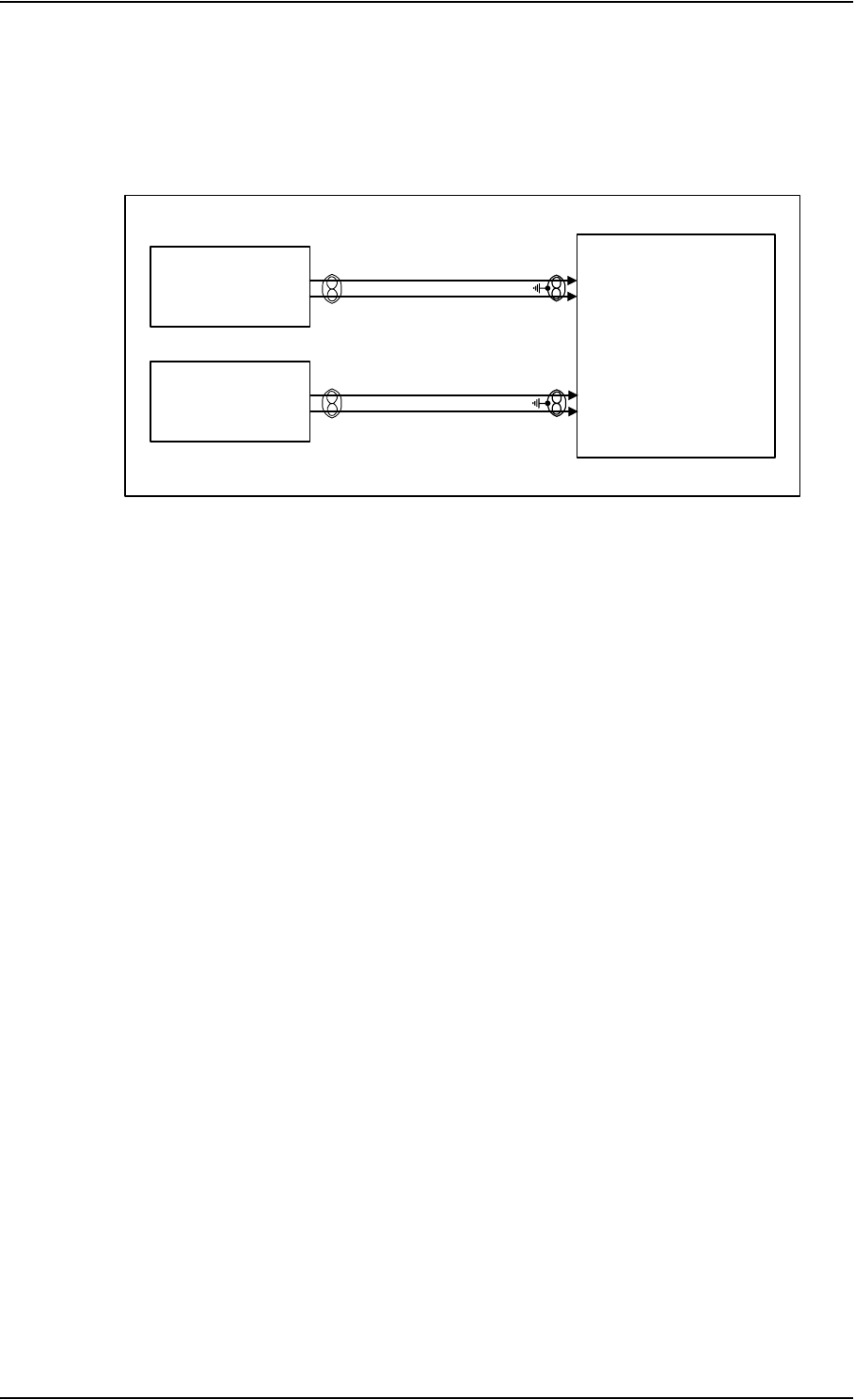
Electrical Installation and Wiring
5-52 Chapter 5: Installation TT98-113625-D
5.3.13 Wiring Sigma7 (2-Wire) Handsets
The following drawing shows the wiring of Sigma7 handsets.
One or two Sigma7 handsets can be connected to the 2-wire interfaces of the
Aero-HSD+ system.
Connect J1 on the Sigma7 handset to the rear receptacle of the SDU according to
the wiring drawing above.
Important! In order for the volume in the Sigma7 handset to be sufficient, it is
normally necessary to adjust the “ear volume” using the menu
system of the handset. For information on how to do this, see
Sigma7 on page 6-9.
For information on the 2-wire interface, see 2-Wire Interfaces on page 5-41.
Figure 5-22: Wiring Sigma7 Handsets
2-WIRE FAX/MODEM (POTS) #2
Sigma
7
Cradle
2-WIRE FAX/MODEM (POTS) #1
TT-5035A
SDU
TP19
TP6
TP8
TP7
J1, pin3
J1, pin4
Sigma
7
Cradle
J1, pin3
J1, pin4
Handset Interface #5
Handset Interface #6
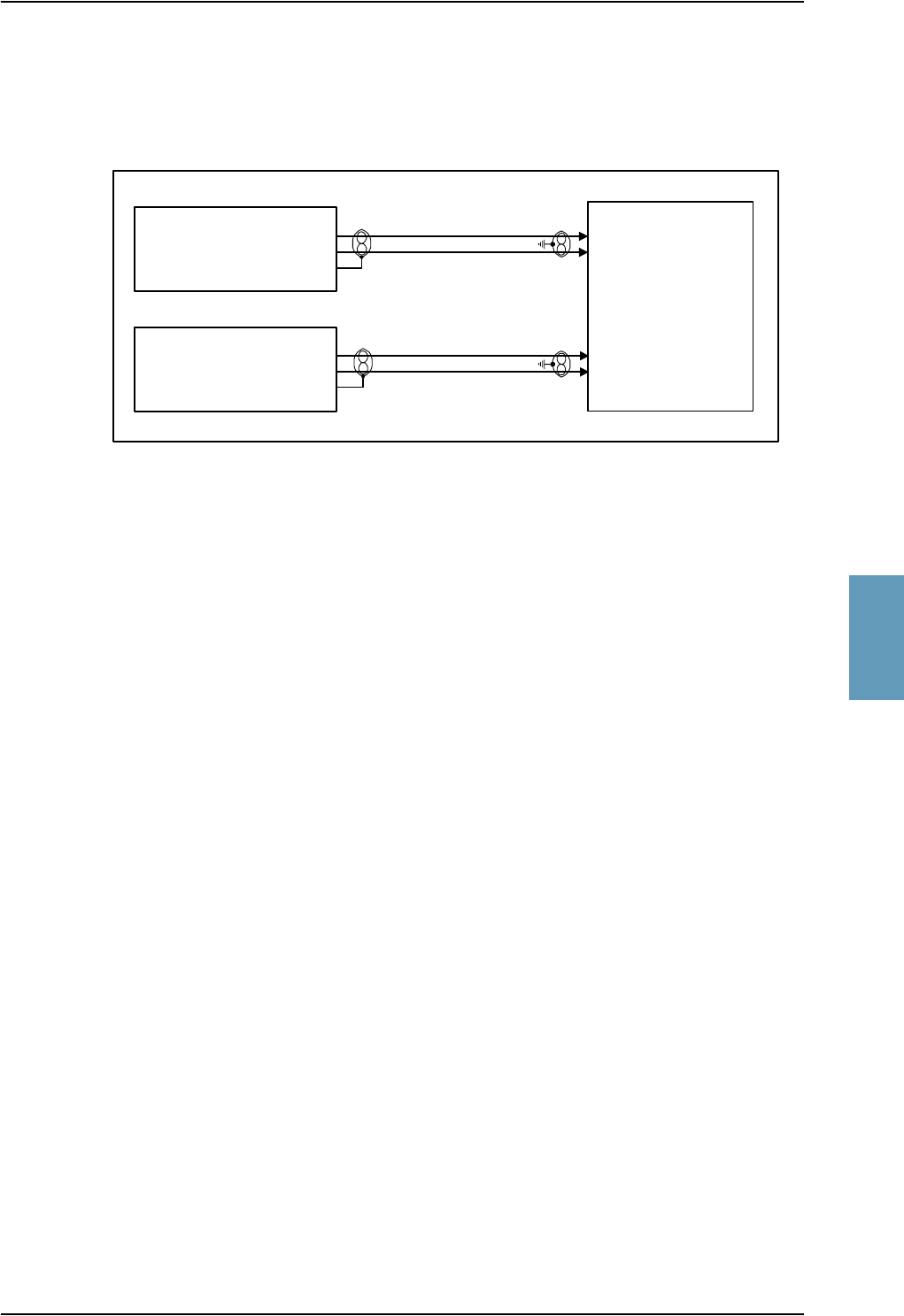
Electrical Installation and Wiring
TT98-113625-D Chapter 5: Installation 5-53
5555
5.3.14 Wiring 2.4GHz Cordless (2-Wire) Phone
The following drawing shows the wiring of 2.4GHz Cordless 2-wire phones.
One or two 2.4GHz Cordless phones can be connected to the 2-wire interfaces of
the Aero-HSD+ system.
Connect J2 on the base unit of the 2.4GHz Cordless phone to the rear receptacle of
the SDU according to the wiring drawing above.
Important! In order for the 2.4GHz Cordless phone to work properly, it is
normally necessary to make a few initial adjustments of the
handset. For information on how to do this, see 2.4GHz Cordless
on page 6-10.
For information on the 2-wire interface, see 2-Wire Interfaces on page 5-41.
Figure 5-23: Wiring 2.4GHz Cordless Handsets
2-WIRE FAX/MODEM (POTS) #2
2.4GHz Cordless
Base Unit
2-WIRE FAX/MODEM (POTS) #1
TT-5035A
SDU
TP19
TP6
TP8
TP7
J2, pin1
J2, pin3
J2, pin2
2.4GHz Cordless
Base Unit
J2, pin1
J2, pin3
J2, pin2
Handset Interface #5
Handset Interface #6
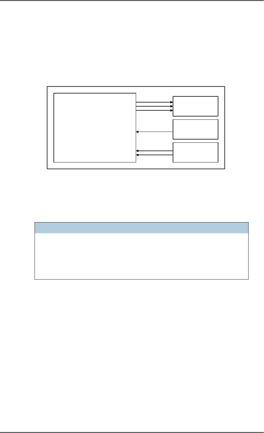
Electrical Installation and Wiring
5-54 Chapter 5: Installation TT98-113625-D
5.3.15 Wiring Discretes
Discrete Annunciators and WOW
The following drawing shows the wiring of discrete annunciators and Weight-on-
Wheels (WOW).
Discrete Annunciators
The following list shows the pins used for Discrete Annunciators:
Note: The Service Available Annunciator on pin BP89 is not available if you
are using handset interface #3 for MagnaStar, 2.4GHz Cordless (4-wire)
or WH-10 Handsets.
Figure 5-24: Wiring Discrete Annunciators and Weight-on-Wheels
SDU Pin Name/Description Specification of discrete typea
a. The discrete interfaces are described in Description of the Discrete Types on
page 5-57.
BP89 Service Available Annunciator
(Discrete I/O)
Output: Lamp Driver
BP92 Call Annunciator (Discrete I/O) Output: Lamp Driver
BP93 Fax Annunciator (Discrete Output) Output: Lamp Driver
Table 5-28: SDU Pins for Discrete Annunciators
Discrete
Annunciators
SERVICE AVAILABLE, BP89
CALL ANNUNCIATOR, BP92
FAX ANNUNCIATOR, BP93
TT-5035A
SDU
Weight-On-
Wheels
WoW input #1, BP50
WoW input #2, BP51
Chime/Lamps
Inhibit
Chime/Lamps Inhibit, BP88

Electrical Installation and Wiring
TT98-113625-D Chapter 5: Installation 5-55
5555
The function of the Annunciators is as follows:
• Service Available Annunciator.
This Annunciator is used for indicating service availability. The Annunciator is
“steady ON” when H+ service is available.
• Call Annunciator.
This Annunciator is used for signalling incoming voice calls. The Annunciator
is “flashing” like the Connection LED on a 4-wire handset and is turned off
when the call is answered or terminated by initiator.
• Fax Annunciator.
This Annunciator is used for signalling incoming fax. The Annunciator is
“steady ON” until a receipt for the fax has been given in the handset.
Chime/Lamps Inhibit Input
Pin used for the Chime/Lamps Inhibit input:
The SDU has one discrete input for the Chime/Lamps Inhibit function. This input
is used to inhibit Satcom activation of the chime and call lights during take-off and
landing. The Inhibit function is activated by connecting this input to ground.
The Inhibit function also activates the ring profile “TakeOfLandng”.
The ring profiles are defined using the HSD+ Configuration Program where call
inhibit/non-inhibit is set up for each of the 4-wire and 2-wire interfaces and
annunciators.
SDU Pin Name/Description Specification of discrete typea
a. The discrete interfaces are described in Description of the Discrete Types on
page 5-57.
BP88 Chime/Lamps Inhibit Input Input: WOW (active low)
Table 5-29: SDU Pins for WOW

Electrical Installation and Wiring
5-56 Chapter 5: Installation TT98-113625-D
Weight-On-Wheels (not currently in use)
The following list shows the pins used for Weight-On-Wheels (WOW):
The SDU has 2 discrete inputs for Weight-On-Wheels (WOW), which can detect
whether the aircraft is airborne or not. Currently this information is not used in the
SDU.
The interpretation of the polarity (airframe DC ground or open circuit) of the input
is defined by the Configuration Module (WOW Active Polarity).
The Configuration Module also defines if WOW is installed or not. For further
information, see the online help in the Aero-HSD+ Configuration Program.
SDU Pin Name/Description Specification of discrete typea
a. The discrete interfaces are described in Description of the Discrete Types on
page 5-57.
BP50 Weight-on-Wheels Input #1 Input: WOW
BP51 Weight-on-Wheels Input #2 Input: WOW
Table 5-30: SDU Pins for WOW

Electrical Installation and Wiring
TT98-113625-D Chapter 5: Installation 5-57
5555
Description of the Discrete Types
Discrete type and description:
Discrete Type Description
Lamp Driver The SDU has several discrete Lamp Driver outputs. The output
configuration forms a switch closure to ground. The electrical
specification for the Lamp type switch is:
Open switch hold-off voltage: max. +39.5 V DC
Closed switch voltage: max. 1 V DC at 500 mA
Open switch resistance (OFF): min. 100 kΩ
WOW The discrete WOW input detects the following states:
“Open” voltage: 7 V DC to 39.5 V DC or ≥100 kΩ to ground.
“Short” voltage: 0 ±3.5 V DC or ≤1500 Ω to ground.
Input characteristics:
Reaction time is <500 ms.
The internal interface is diode-isolated for parallel connection
externally to any other LRU(s), with at least 200 kΩ of isolation,
when power is not applied.
Table 5-31: Specification of Discrete Types.
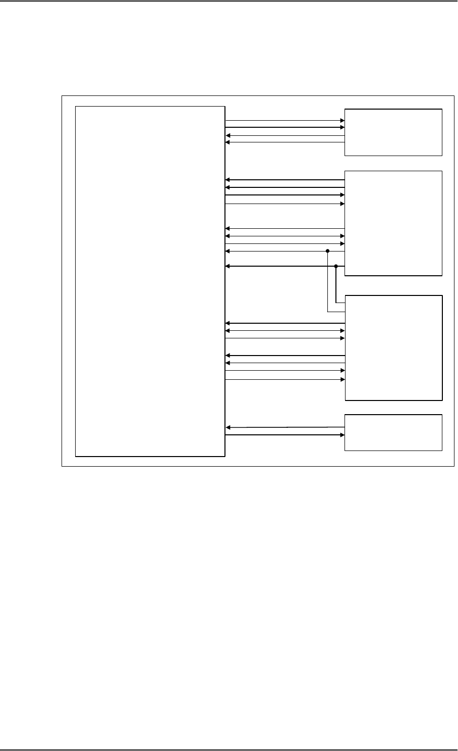
Electrical Installation and Wiring
5-58 Chapter 5: Installation TT98-113625-D
5.3.16 Cockpit Voice and SIM Card Reader (Future Use)
The following drawing shows the wiring of Cockpit Voice and SIM Card reader:
Do not connect equipment to the SIM Card pins, as any implementation of a SIM
CARD system must wait for a future interface definition.
The Cockpit Voice interface is physically prepared, but the software is not imple-
mented yet.
Figure 5-25: Wiring Cockpit Voice and SIM Card Reader
TT-5035A
SDU
BP70
BP71
BP72
BP73
Tx B
Tx A
Rx B
Rx A
Call Cancel Input #1
Voice Mic On Input #1
VOICE Call Light Output #1
Chime / Lamps Inhibit Input
Chime Reset Input
BP82
BP83
BP84
BP91
BP88
Cockpit Voice #1
(Future use)
TP10
TP11
TP12
TP13
CPV Audio #1 In Lo
CPV Audio #1 In Hi
CPV Audio #1 Out Hi
CPV Audio #1 Out Lo
Call Cancel Input #2
Voice Mic On Input #2
VOICE Call Light Output #2
BP85
BP86
BP87 Cockpit Voice #2
(Future use)
TP15
TP16
TP17
TP18
CPV Audio #2 In Lo
CPV Audio #2 In Hi
CPV Audio #2 Out Hi
CPV Audio #2 Out Lo
RS-422 SIM Card
Reader
(Future use)
BP52
BP53
Chime Signal Contact #1
Chime Signal Contact #2 Chime
(Future use)
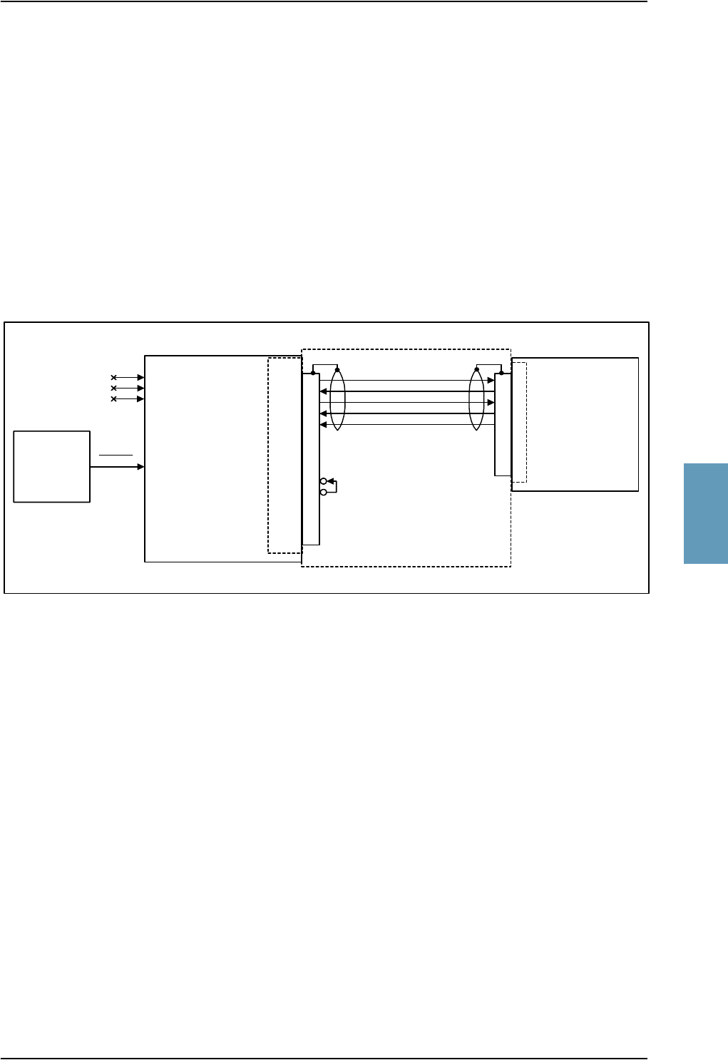
Electrical Installation and Wiring
TT98-113625-D Chapter 5: Installation 5-59
5555
5.3.17 Wiring Maintenance Handset, PC and Reset
Maintenance PC, CM Write Enable, SDU Reset and ATE
The following drawing shows the wiring of:
• the RS-232 PC connection,
• SDU Reset,
• Write enable for the Configuration Module and
• ATE interface (for test only)
Figure 5-26: Wiring Maintenance PC and Reset
TT-5035A
SDU
RESET BP77
FP10
FP11
FP12
FP13
FP9
FP15
FP8
GND, Power Return
Maintenance
PC
RS-232C RTS
RS-232C RXD
RS-232C TXD
RS-232C CTS
BP74, ATE 1
BP75, ATE 2
BP76, ATE 3
(Do not connect)
SDU
Reset
DB15F
DB15M
10
11
12
13
9
1
2
3
4
15
8
5
6
7
14
DB9F
2
3
8
7
5
1
4
6
9
CM Write Enable
Data Cable TT 37-112940
+12 V DC
DB9M
2
3
8
7
5

Electrical Installation and Wiring
5-60 Chapter 5: Installation TT98-113625-D
RS-232 Maintenance PC Interface and “Write Enable” Input for Configuration Module
The following list shows the SDU pins used for RS-232 PC interface and for CM
Write Enable. Both interfaces are included in the TT 37-112940 data cable
described at the end of this section.
The SDU has a PC interface at the front connector, supporting the RS-232
standard. The front PC interface can also be used for uploading software, or it can
serve as a printer interface.
The interface is configured as DCE on the SDU (i.e. TxD + RTS are inputs and
RxD + CTS are outputs).
The PC interface has the following characteristics:
• Baud rate: 115.2 kbit/s fixed
• Data bits: 8
• Parity: None
• Stop bit: 1
• Flow control: Hardware (RTS/CTS only)
The Write Enable Input - FP15 - enables write cycles to the write protected area in
the Configuration Module. FP15 must be connected to +12 V DC (FP8) in order to
have access to the write protected area. Electrical specifications:
Enable Write cycles: +10.0 V ≤ VFP15 ≤ +13.0 V
Write Protected: VFP15 ≤ +1.9 V
SDU Pin Name/Description
FP10 TxD Input
FP11 RxD Output
FP12 RTS Input
FP13 CTS Output
FP9 GND, Power Return (for +12 V DC)
FP8 +12 V DC/120 mA
FP15 Configuration Module Write Enable In
Table 5-32: SDU Pins for RS-232 PC Interface
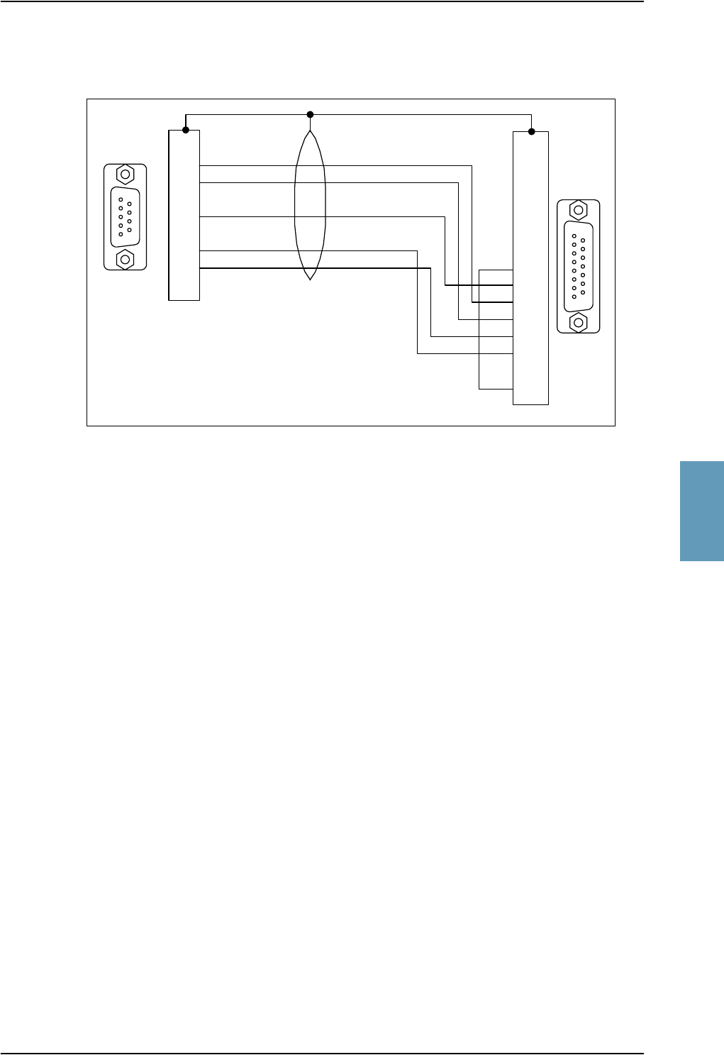
Electrical Installation and Wiring
TT98-113625-D Chapter 5: Installation 5-61
5555
The following drawing shows the wiring of the data cable for the front connector.
Reset
The SDU has a discrete input (BP77) on the rear connector, which can be used for
SDU hardware reset. The specification complies with the discrete WOW input.
Note: You only need to connect this input if you have special requirements to
the reset function. For normal use, the push-button on the front panel of
the SDU should be sufficient.
SDU hardware reset is initiated by connecting the input to ground. This input is
filtered carefully, and the input must be activated for approximately 5 sec. before
the reset procedure takes action. It is highly recommended to use a guarded switch
to avoid accidental operation of the switch.
Electrical DC characteristics: WOW Input type, refer to Description of the
Discrete Types on page 5-57.
Automatic Test Equipment Pins
The TT-5035A SDU Rear Connector Bottom Plug (BP) has pins for automatic test
equipment (ATE): ATE 1 (BP74), ATE 2 (BP75) and ATE 3 (BP76).
Important! Do not connect anything to the ATE pins, not even ground, as
lightning-induced effects can potentially harm the internal circuits,
and even grounding these pins can cause unintended function of the
system.
Figure 5-27: TT 37-112940 Data Cable Compliant with Front Connector
5
16
9
815
9
1
1
2
3
4
5
6
7
8
9
1
2
3
4
5
6
7
8
9
10
11
12
13
14
15
DB15
Male
DB9
Female
GND
RXD
TXD
CTS
RTS
Housing: Metal
Housing: Metal
Data Cable TT 37-112940
(3 meter)
To PC
To SDU

Electrical Installation and Wiring
5-62 Chapter 5: Installation TT98-113625-D
Maintenance Handset Interface
The following drawing shows the wiring of the maintenance handset interface to
the front connector of the SDU.
The following list shows the pins used for maintenance handset interface.
The SDU has a handset interface for the TT-5620A Handset for maintenance use.
This interface can be used to access the menu system using a 4-wire handset.
The front connector provides +12 V DC handset power (FP8). The RS-485 bus on
the front connector is common with the RS-485 bus for Handset #4 on the rear
connector. The Maintenance handset provides a common mode voltage
(2.5 V DC) on the Audio In lines to the SDU. This voltage is used to detect the
presence of the handset on the front connector, so the RS-485 #4 can be redirected
to the front connector.
Figure 5-28: Wiring Maintenance Handset
SDU Pin Function: Handset Interface
FP1 Maintenance Handset Audio In Hi
FP2 Maintenance Handset Audio In Lo
FP3 Maintenance Handset Audio Out Hi
FP4 Maintenance Handset Audio Out Lo
FP6 Maintenance Handset RS-485 Data A
FP7 Maintenance Handset RS-485 Data B
FP8 +12 V DC/120 mA
FP9 GND Power Return (for +12 V DC)
Table 5-33: SDU Pins for Maintenance Handset Interface
TT-5035A
SDU
GND, Power Return
FP8
FP9
FP6
FP7
FP3
FP4
FP1
FP2
Front Connector
(DB15F)
+12 V DC / 120 mA
RS-485 RX/TX A
RS-485 RX/TX B
4-Wire Telep. Line Tx
4-Wire Telep. Line Rx
Maintenance
Cradle
TT 5622A
DB15F DB15M
1
2
3
8
9
12
15
4
5
10
11
13
14
6
7
DB15M
15
14
13
12
11
10
5
8
9
6
7
3
4
1
2
1
2
3
8
9
12
15
4
5
10
11
13
14
6
7
Note: The TT 5622A cradle is delivered with
the DB15M connector mounted on a "pigtail".

Electrical Installation and Wiring, HSU
TT98-113625-D Chapter 5: Installation 5-63
5555
5.4 Electrical Installation and Wiring, HSU
5.4.1 Introduction to HSU
As an option, a High Speed data Unit (HSU) containing one additional HSD
channel is available for the Aero-HSD+ system, providing a total data rate of 128
kbit/s.
The following pages provide information on wiring of the units in the Aero-HSD+
system with an additional High Speed data Unit (HSU) installed.
5.4.2 Wiring HSU Power Supply
The SDU to Aircraft power bus interfaces supply the electric power required to
operate the HSU, and for EMC purposes a chassis connection to the aircraft
chassis and the installation tray. The +28 V DC Power wire must include a circuit
breaker capable of carrying the required current continuously under the required
environmental conditions.
The following drawing shows the wiring of the HSU to the Aircraft Power Bus.
Figure 5-29: Wiring HSU Power
TT-5038A
HSU
[2] TP2 GND, Power Return
28 V DC
Aircraft Power Bus
[1] Total resistance max. 725 mΩ incl. Circuit Breaker.
[2] Total resistance max. 25 mΩ.
[3] Directly to Aircraft chassis, max. 1 m cable length to prevent EMC problems and
max. 25 mΩ resistance.
[4] Recommended circuit breaker: Klixon 2TC series, 4 A current rating.
TP3
TP1 +28 V DC Power
Chassis Ground
[4]
4A
[1]
[3]
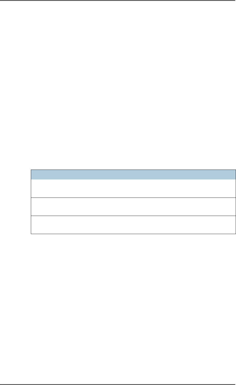
Electrical Installation and Wiring, HSU
5-64 Chapter 5: Installation TT98-113625-D
+28 V DC Power
It is essential to keep the line impedance below the specified limits. See Cable
Requirements, HSU Power Supply on page 5-64.
Reverse polarity protection is only guaranteed if the suggested circuit breaker is
used.
Required current capability for the Circuit Breaker: 23 W @ 17.7 V DC which
equals 1.3 A DC at the required environmental conditions.
A suitable circuit breaker with sufficient low resistance would be Klixon 2TC
series with 4 A current rating.
Chassis Ground
The Chassis connection ensures that the HSU cabinet and the installation tray has
the same potential, and that there is a connection from the cable shields to the
cabinet for EMC purposes.
Connect the wire directly to the installation tray and to aircraft chassis.
Cable Requirements, HSU Power Supply
Note: For maximum allowed cable lengths, see Power Cables, Allowed Cable
Lengths on page 5-81.
Cablea
a. The cable numbers refer to the numbers stated on the wiring drawing in the section
Figure 5-29: Wiring HSU Power.
Max. Resistance Other Requirements
[1]
(+28 V DC Power)
725 mΩ,
incl. circuit breaker
[2]
(GND, Power Return)
25 mΩThe cable should be as short as possible.
[3]
(Chassis Ground)
25 mΩConnect directly to aircraft chassis.
Table 5-34: Requirements to HSU Power Cables
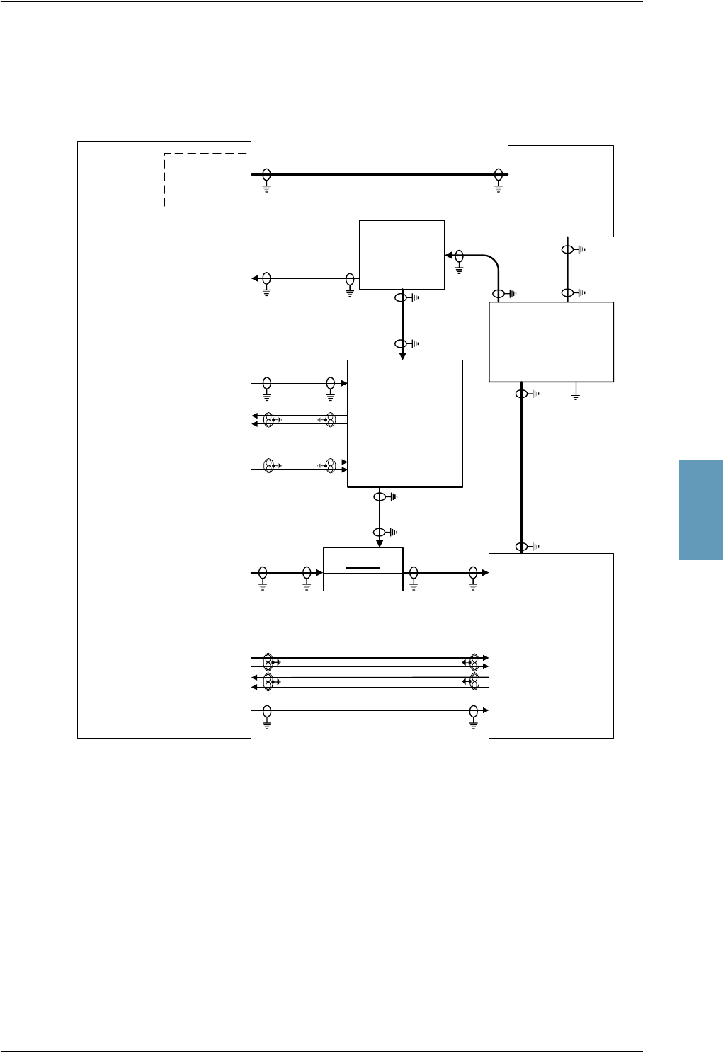
Electrical Installation and Wiring, HSU
TT98-113625-D Chapter 5: Installation 5-65
5555
5.4.3 Wiring Antenna Systems With HSU Installed
HGA-7000 Antenna with HSU
Figure 5-30: Wiring HSU to HGA-7000 Antenna System
HSU TX Coupler
TT-5038A-002
TT-5035A
SDU
HGA-7000
TP A4 J2 IF2
J1 IF1
Built-in
BSU
W7 [6]
TT-5012A
DLNA
X3 TX
X1 RX X2 Ant
GND
[7]
Power
Splitter
3.5 dB @1.6GHz
HSU
SDU
DLNA
HSU RX Power Splitter
TT-5038A-003
TT-5038A
HSU
ARINC 429
BP56
BP32
BP33
BP34
BP35
TP8
TP19
TP20
TP21
TP22
ARINC 429
HSU disable
TP A1
TP A2
SDU HPA
HSU
TP2
TT-5014A
HPA
TP1
BP78
BP79
BP80
BP81
HPA nON
BP57 BP6
BP27
BP28
BP25
BP26
HPA CONTROL
BITE / STATUS
TP A1
TP A2
W3[4], [5]
RF RX COAX [1], [2]
RF RX COAX [2]
W4 [4]
RF TX COAX
Loss_3 [3]
RF TX COAX
Loss_1 [3]
RF TX COAX
Loss_2 [3]
RF RX COAX [1]
[1] The total cable loss - including the power splitter loss (3.5 dB) - between the DLNA and the SDU must be: 0 to 15 dB @ 1.6 GHz
[2] The total cable loss - including the power splitter loss (3.5 dB) - between the DLNA and the HSU must be: 0 to 12 dB @ 1.6 GHz
[3] The cable losses from HSU/SDU to HPA are:
Loss_1: The cable loss from SDU to Tx Coupler
Loss_2: The cable loss from Tx Coupler to HPA
Loss_3: The cable loss from HSU to Tx Coupler
The cable loss limits are:
Loss_3 <= 2.5 dB + Loss_1 @ 1.6 GHz
Loss_1 + Loss_2 <= 11.0 dB @ 1.6 GHz
[4] Coax, total loss from cable W3 and cable W4 max. 1.8 dB @ 1.6 GHz
[5] Coax, loss from cable W3 max. 0.3 dB @ 1.6 GHz
[6] Coax, loss from cable W7 max. 17 dB @ 1.6 GHz
[7] 16 AWG, max. 1 ft long, max. resistance 3 mΩ

Electrical Installation and Wiring, HSU
5-66 Chapter 5: Installation TT98-113625-D
Important! The Power Splitter must be connected correctly, because the HSU
port has a built-in DC block.
Requirements to the cables are stated in the drawing and in the section RF Cable
requirements, HGA-7000 Antenna With HSU on page 5-68.
The following lists show the HSU, SDU and HPA pins in the Aero-HSD+ system
used for connecting a HGA-7000 antenna system.
HSU pin Description
TP A1 RF Rx input from HSU Rx Power Splitter
TP A2 RF Tx output to HSU Tx Coupler
TP8 HSU Disable input
TP19 Data bus output to SDU (ARINC 429-A)
TP20 Data bus output to SDU (ARINC 429-B)
TP21 Data bus input from SDU (ARINC 429-A)
TP22 Data bus input from SDU (ARINC 429-B)
Table 5-35: HSU Pins for HGA-7000 Antenna System
SDU pin Description
TP A1 RF Rx input from HSU Rx Power Splitter
TP A2 RF Tx output to HSU Tx Coupler
TP A4 Antenna Modem Interface
BP32 Data bus input from HSU (ARINC 429-A)
BP33 Data bus input from HSU (ARINC 429-B)
BP34 Data bus output to HSU (ARINC 429-A)
BP35 Data bus output to HSU (ARINC 429-B)
BP56 HSU Disable output
BP57 HPA remote nOn/Off output
BP78 HPA Control Output A, RS-422
BP79 HPA Control Output B, RS-422
BP80 HPA Data/BITE Input A, RS-422
BP81 HPA Data/BITE Input B, RS-422
Table 5-36: SDU Pins for HGA-7000 Antenna System

Electrical Installation and Wiring, HSU
TT98-113625-D Chapter 5: Installation 5-67
5555
ARINC 429 Interface (TP19-TP22)
The ARINC 429 interface is used by the SDU to control the HSU. The HSU
operates as a slave to the SDU. The Interface is a 100 kbit/s High Speed
ARINC 429 duplex data bus to/from the SDU. For electrical specifications refer to
the ARINC 429 standard [6].
HSU Disable (TP8)
The SDU uses the HSU Disable input to reset and inhibit the transmitter output
signal from the HSU. The electrical specification is defined as for the discrete
Weight-On-Wheels input type.
HPA pin Description
TP1 RF Tx output to DLNA
TP2 RF Tx input from HSU Tx Coupler
BP6 Remote nOn/Off input from SDU
BP25 Tx Data/BITE Output A, RS-422, to SDU
BP26 Tx Data/BITE Output B, RS-422, to SDU
BP27 Rx Control Input A, RS-422, from SDU
BP28 Rx Control Input B, RS-422, from SDU
Table 5-37: HPA Pins for HGA-7000 Antenna System

Electrical Installation and Wiring, HSU
5-68 Chapter 5: Installation TT98-113625-D
RF Cable requirements, HGA-7000 Antenna With HSU
Note: For recommended RF cable types, see Recommended RF Cables on
page 5-84.
ARINC 429 Cable requirements, HGA-7000 Antenna With HSU
The cables for the ARINC 429 interfaces must be twisted and shielded and
conform to the standards for aeronautical use.
For recommended cable types, see Recommended Cables for ARINC 429 on
page 5-84.
Cablea
a. The “W” cable numbers refer to the numbers stated on the wiring drawing in Figure
5-30: Wiring HSU to HGA-7000 Antenna System.
Type
Min.
Cable Loss
@1.6 GHz
Max. Cable
Loss
@1.6 GHz
Other
Requirements
W3
(TT-5012A DLNA to
Antenna)
Coax 0 dB 0.3 dB
W4
(HPA to TT-5012A DLNA)
Coax 0 dB 1.8 dB - W3
W3 and W4 Coax 0 dB Total: 1.8 dB
TT-5012A DLNA to SDU
(including Power Splitter
loss 3.5 dB)
Coax 0 dB 15 dB
TT-5012A DLNA to HSU
(including Power Splitter
loss 3.5 dB)
Coax 0 dB 12 dB
RF Tx output from
SDU/HSU to HPA
Coax 0 dB NOTEb
b. With an HSU installed, the cable losses from HSU/SDU to HPA are as follows:
Loss_1: The cable loss from SDU to Directional Coupler
Loss_2: The cable loss from Directional Coupler to HPA
Loss_3: The cable loss from HSU to Directional Coupler
The cable loss limits are:
Loss_3 <= 2.5 dB + Loss_1 @ 1.6 GHz
Loss_1 + Loss_2 <= 11.0 dB @ 1.6 GHz
W7
(Antenna modem interface)
Coax 0 dB 17 dB
GND on TT-5012A DLNA Resistance:
Max. 3 mΩ
Table 5-38: Requirements to RF Cables, HGA-7000 Antenna

Electrical Installation and Wiring, HSU
TT98-113625-D Chapter 5: Installation 5-69
5555
AMT-50 Subsystem With HSU
Figure 5-31: Wiring HSU to AMT-50 Subsystem
HSU TX Coupler
TT-5038A-002
TT-5035A
SDU
AMT-50
Antenna
AMT-50
DLNA
Power
Splitter
3.5 dB @1.6GHz
HSU
SDU
DLNA
HSU RX Power Splitter
TT-5038A-003
TT-5038A
HSU
ARINC 429
BP56
BP32
BP33
BP34
BP35
TP8
TP19
TP20
TP21
TP22
ARINC 429
HSU disable
TP A1
TP A2
SDU HPA
HSU
TP2
TT-5014A
HPA
TP1
BP78
BP79
BP80
BP81
HPA nON
BP57 BP6
BP27
BP28
BP25
BP26
HPA CONTROL
Data/BITE
TP A1
TP A2
RF RX COAX [1], [2]
RF RX COAX [2]
W4
[4]
RF TX COAX
Loss_3 [3]
RF TX COAX
Loss_1 [3]
RF TX COAX
Loss_2 [3]
RF RX COAX [1]
[1] The total cable loss - including the power splitter loss (3.5 dB) - between the DLNA and the SDU must be: 6 to 29 dB @ 1.6 GHz
[2] The total cable loss - including the power splitter loss (3.5 dB) - between the DLNA and the HSU must be: 6 to 25 dB @ 1.6 GHz
[3] The cable losses from HSU/SDU to HPA are:
Loss_1: The cable loss from SDU to Tx Coupler
Loss_2: The cable loss from Tx Coupler to HPA
Loss_3: The cable loss from HSU to Tx Coupler
The cable loss limits are:
Loss_3 <= 2.5 dB + Loss_1 @ 1.6 GHz
Loss_1 + Loss_2 <= 11.0 dB @ 1.6 GHz
[4] Coax, total loss from cable W3 and cable W4 max. 1.8 dB @ 1.6 GHz
[5] Coax, loss from cable W3 max. 0.3 dB @ 1.6 GHz
AMT-50
ACU
A B H G
W3
[4] [5)
BP8
BP9
BP13
BP14
A429 Tx (HS)
A429 Rx (LS)
J3
J1
J2
AMT-50 Subsystem

Electrical Installation and Wiring, HSU
5-70 Chapter 5: Installation TT98-113625-D
The following lists show the HSU, SDU and HPA pins in the Aero-HSD+ system
used for connecting an AMT-50 antenna subsystem.
HSU pin Description
TP A1 RF Rx input from HSU Rx Power Splitter
TP A2 RF Tx output to HSU Tx Coupler
TP8 HSU Disable input
TP19 Data bus output to SDU (ARINC 429-A)
TP20 Data bus output to SDU (ARINC 429-B)
TP21 Data bus input from SDU (ARINC 429-A)
TP22 Data bus input from SDU (ARINC 429-B)
Table 5-39: HSU Pins for HGA-7000 Antenna System
SDU pin Description
TP A1 RF Rx input from HSU Rx Power Splitter
TP A2 RF Tx output to HSU Tx Coupler
BP32 Data bus input from HSU (ARINC 429-A)
BP33 Data bus input from HSU (ARINC 429-B)
BP34 Data bus output to HSU (ARINC 429-A)
BP35 Data bus output to HSU (ARINC 429-B)
BP56 HSU Disable output
BP57 HPA remote nOn/Off output
BP78 HPA Control Output A, RS-422
BP79 HPA Control Output B, RS-422
BP80 HPA Data/BITE Input A, RS-422
BP81 HPA Data/BITE Input B, RS-422
Table 5-40: SDU Pins for HGA-7000 Antenna System

Electrical Installation and Wiring, HSU
TT98-113625-D Chapter 5: Installation 5-71
5555
HSU ARINC 429 Interface (TP19-TP22)
The ARINC 429 interface on HSU pins TP19-TP22 is used by the SDU to control
the HSU. The HSU operates as a slave to the SDU. The Interface is a 100 kbit/s
High Speed ARINC 429 duplex data bus to/from the SDU. For electrical
specifications refer to the ARINC 429 standard [6].
HPA ARINC 429 Interface (BP8, BP9, BP13, BP14 on HPA)
An ARINC 429 high speed Tx interface and an ARINC 429 low speed Rx
interface is used for communication between the HPA and the AMT-50 ACU.
HSU Disable (TP8)
The SDU uses the HSU Disable input to reset and inhibit the transmitter output
signal from the HSU. The electrical specification is defined as for the discrete
Weight-On-Wheels input type.
HPA pin Description
TP1 RF Tx output to DLNA
TP2 RF Tx input from HSU Tx Coupler
BP6 Remote nOn/Off input from SDU
BP8 A429 Tx A output to AMT-50 ACU
BP9 A429 Tx B output to AMT-50 ACU
BP13 A429 Rx1 A input from AMT-50 ACU
BP14 A429 Rx1 B input from AMT-50 ACU
BP25 Tx Data/BITE Output A, RS-422, to SDU
BP26 Tx Data/BITE Output B, RS-422, to SDU
BP27 Rx Control Input A, RS-422, from SDU
BP28 Rx Control Input B, RS-422, from SDU
Table 5-41: HPA Pins for HGA-7000 Antenna System

Electrical Installation and Wiring, HSU
5-72 Chapter 5: Installation TT98-113625-D
RF Cable requirements, AMT-50 Subsystem With HSU
ARINC 429 Cable requirements, AMT-50 Subsystem System With HSU
The cables for the ARINC 429 interfaces must be twisted and shielded and
conform to the standards for aeronautical use.
For recommended cable types, see Recommended Cables for ARINC 429 on
page 5-84.
Cablea
a. The “W” cable numbers refer to the numbers stated on the wiring drawing in Figure
5-31: Wiring HSU to AMT-50 Subsystem.
Type Min. Cable Loss
@1.6 GHz
Max. Cable
Loss@1.6 GHz
W3
(ARINC 741 DLNA to
Antenna)
Coax 0 dB 0.3 dB
W4
(HPA to ARINC 741 DLNA)
Coax 0 dB 1.8 dB - W3
W3 and W4 0 dB Total: 1.8 dB
ARINC 741 DLNA to SDU
(including Power Splitter loss
3.5 dB)
Coax 6 dB 29 dB
ARINC 741 DLNA to HSU
(including Power Splitter loss
3.5 dB)
Coax 6 dB 25 dB
RF Tx output from
SDU/HSU to HPA
Coax 0 dB NOTEb
b. With an HSU installed, the cable losses from HSU/SDU to HPA are as follows:
Loss_1: The cable loss from SDU to Directional Coupler
Loss_2: The cable loss from Directional Coupler to HPA
Loss_3: The cable loss from HSU to Directional Coupler
The cable loss limits are:
Loss_3 ≤ 2.5 dB + Loss_1 @ 1.6 GHz
Loss_1 + Loss_2 ≤ 11.0 dB @ 1.6 GHz
Table 5-42: Requirements to RF Cables, AMT-50 Subsystem
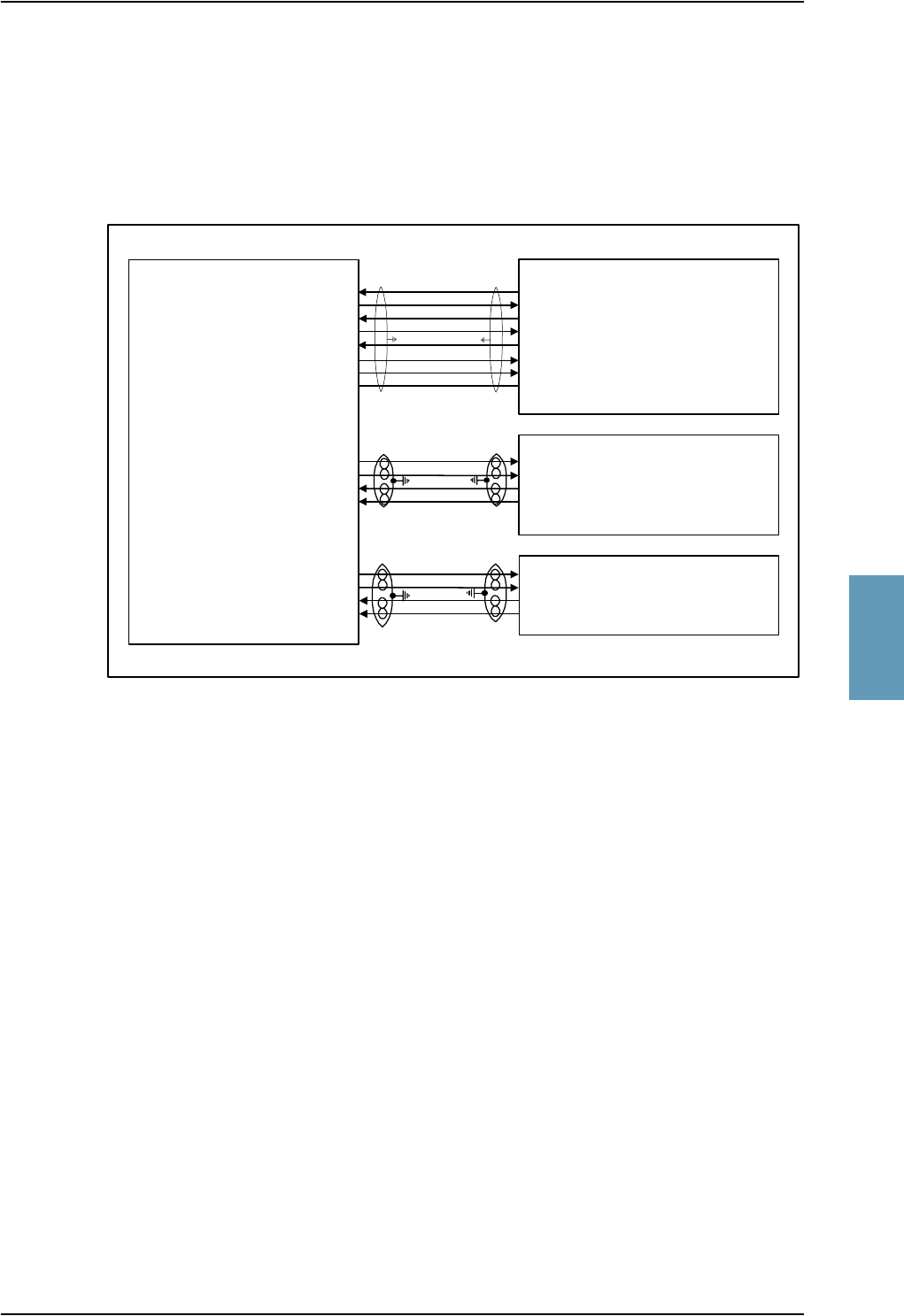
Electrical Installation and Wiring, HSU
TT98-113625-D Chapter 5: Installation 5-73
5555
5.4.4 Wiring HSU to MPDS RS-232 , MPDS Ethernet and
ISDN
The following drawing shows the wiring of the HSU to MPDS RS-232, MPDS
10BaseT Ethernet and ISDN.
Figure 5-32: Wiring HSU to MPDS RS-232, MPDS Ethernet and ISDN
MPDS
(DTE)
ISDN
(TE)
RJ45 Female Connector
ISDN Tx+ (d) Output, TP24
ISDN Tx- (e) Output, TP25
ISDN Rx+ (c) Input, TP23
ISDN Rx- (f) Input, TP26
MPDS
Ethernet 10BaseT
(DTE)
RJ45 Female Connector
MPDS TxD Input, TP11
MPDS RxD Output, TP12
MPDS RTS Input, TP13
MPDS CTS Output, TP14
MPDS DTR Input, TP15
MPDS DCD Output, TP16
MPDS DSR Output, TP17
MPDS GND, TP18
TT-5038A
HSU
Rx Output, TP A3
Tx Input, TP A4
DCE
EIA/TIA-232-E
NT1
DCE
3, RxD+ Input
6, RxD- Input
1, TxD+ Output
2, TxD- Output
3 Rx+ input
6 Rx- input
4 Tx+ output
5 Tx- output
TxD Output
RxD Input
RTS Output
CTS Input
DTR Output
DCD Input
DSR Input
GND

Electrical Installation and Wiring, HSU
5-74 Chapter 5: Installation TT98-113625-D
MPDS RS-232 Pins
The MPDS interface is an EIA/TIA-232-E 115.2 kbit/s Asynchronous RFC 1549
HDLC interface (www.ietf.org).
Configuration: DCE (i.e. TxD is an input and RxD is an output), with hardware
flow control (RTS, CTS, DTR, DCD, DSR as EIA/TIA-232-E signals).
Baud rate (Rx Output): 115.2 kbit/s ± 1 ppm.
Baud rate (Tx Input): 115.2 kbit/s ± 4%
To be compliant with EIA/TIA 232-E a female 25 pin SUB D connector or a
female 9 pin SUB D connector must be connected to the MPDS lines from the
HSU. The lines must be connected as shown in the table above.
HSU pin Name/Description
Equivalent
DB9F
Pin no.
Equivalent
DB25F
Pin no.
TP11 MPDS TxD Input (EIA/TIA-232-E) 3 2
TP12 MPDS RxD Output (EIA/TIA-232-E) 2 3
TP13 MPDS RTS Input (EIA/TIA-232-E) 7 4
TP14 MPDS CTS Output (EIA/TIA-232-E) 8 5
TP15 MPDS DTR Input (EIA/TIA-232-E) 4 20
TP16 MPDS DCD Output (EIA/TIA-232-E) 1 8
TP17 MPDS DSR Output (EIA/TIA-232-E) 6 6
TP18 MPDS GND (EIA/TIA-232-E) 5 7
Table 5-43: HSU Pins for MPDS RS-232

Electrical Installation and Wiring, HSU
TT98-113625-D Chapter 5: Installation 5-75
5555
MPDS Ethernet 10BaseT Pins
The following list shows the pins used for the MPDS Ethernet interface
The pin-outs for TP A3 and TP A4 are specified in Figure 5-33: Ethernet RxD
Twinax Contact Pin-out Definition and Figure 5-34: Ethernet TxD Twinax
Contact Pin-out Definition.
TP A3 is a 10BaseT Ethernet Rx twinax output for 100 Ω twisted pair medium.
The pin-out is as follows:
TP A4 is a 10BaseT Ethernet Tx twinax input for 100 Ω twisted pair medium.
The pin-out is as follows:
HSU pin Name Description RJ45 PIN (F) Name
TP A4 (center) Tx+ Input 1 TxD+
TP A4 Tx- Input 2 TxD-
TP A3 (center) Rx+ Output 3 RxD+
TP A3 Rx- Output 6 RxD-
Table 5-44: HSU Pins for MPDS 10BaseT Ethernet
Figure 5-33: Ethernet RxD
Twinax Contact Pin-out Definition
Figure 5-34: Ethernet TxD Twinax
Contact Pin-out Definition
Shield
RxD+ Output
RxD- Output
Shield
TxD+ Input
TxD- Input
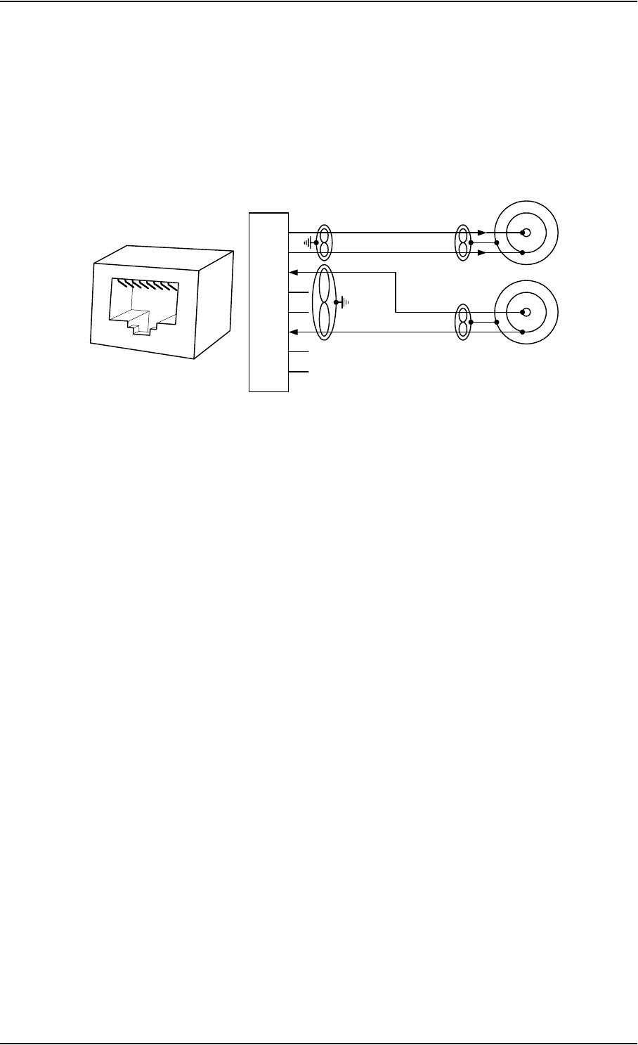
Electrical Installation and Wiring, HSU
5-76 Chapter 5: Installation TT98-113625-D
The 10 Mbit/s Ethernet interface physical layer conforms to [1] (IEEE standard
802.3, Chapter 14: “Twisted Pair medium attachment unit”), except for the
connector type. To be compliant with [1], an RJ45 female connector must be used
for the user interface. The connector pin assignment must be according to [1] and
[2] (ISO8877 ISO/IEC 8877) as shown in Figure 5-35: Ethernet RJ45
Connector and Cable Connection to HSU.
The HSU is defined as a DCE or a Hub i.e. TxD is input and RxD is output.
Cable Requirements, MPDS Ethernet 10BaseT on HSU
The cable for the MPDS Ethernet 10BaseT interface for the HSU must be a 100 Ω
2-wire twisted and shielded cable.
Figure 5-35: Ethernet RJ45 Connector and Cable Connection to HSU.
1
2
3
4
5
6
7
8
TxD+ TX+ input
n.c.
TxD- TX- input
RxD+
RX+ output
n.c.
RxD- RX- output
n.c.
n.c.
RJ45
female HSU pin
TP A4
to DTE
100Ω Twinax twisted
and shielded pairs
HSU (DCE/Hub)
12345678
HSU pin
TP A3
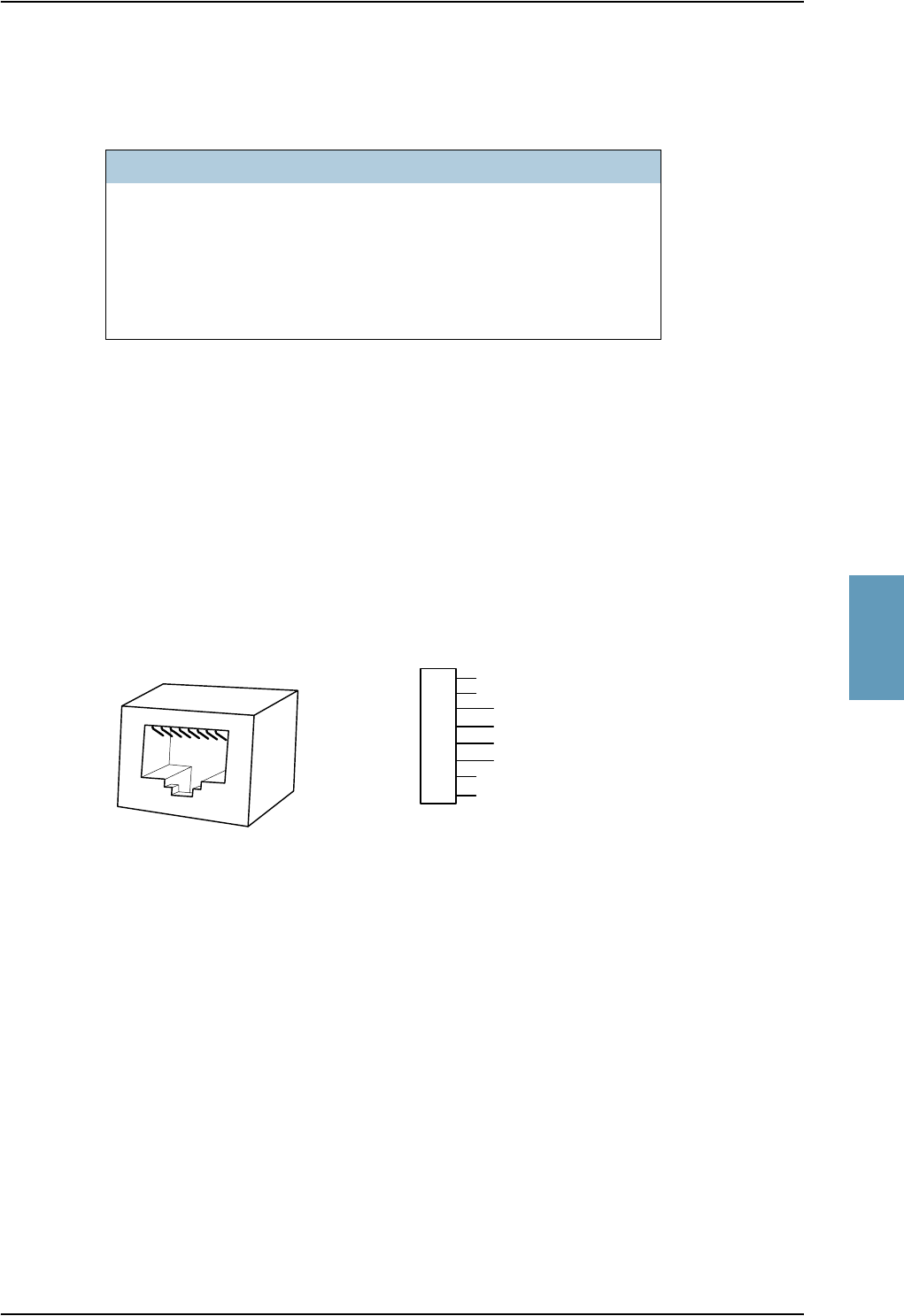
Electrical Installation and Wiring, HSU
TT98-113625-D Chapter 5: Installation 5-77
5555
ISDN Pins
The following list shows the pins used for the ISDN interface.
The HSU is configured as the network side of the NT1 interface i.e. Rx is an input
and Tx is an output. Please note that this configuration of input and output differs
from the configuration of the 10BaseT Ethernet, the MPDS RS-232 interface and
RS-232 PC interface input/output.
To be compliant with ISO8877 [2] and the ISDN connector specification defined
by ITU I.420 [5], an RJ-45 Female Connector must be connected to the four wire
ISDN lines from the HSU. The HSU includes an internal 100 Ω termination
resistor to support cable lengths longer than 3 meters.
The ISDN interface can power supply 4 ISDN phones but supports 8 phones
(where 4 of them must have their own power supply). At power hold-up, only
power for one phone is available i.e. if more than one phone is connected, the
HSU may reset if an incoming call is received, or more than one handset is off-
hook, during a power hold-up session.
Cable Requirements, ISDN
The cable for the ISDN interface must be a 100 Ω 4-wire shielded cable. The
conductors must be twisted in pairs.
HSU pin Name Description RJ45 PIN (F) Name
TP23 ISDN Rx+ (c) Input 3 Rx+
TP24 ISDN Tx+ (d) Output 4 Tx+
TP25 ISDN Tx- (e) Output 5 Tx-
TP26 ISDN Rx- (f) Input 6 Rx-
Table 5-45: HSU Pins for ISDN
Figure 5-36: ISDN RJ45 Connector
1
2
3
4
5
6
7
8
ISDN Rx+ Input
ISDN Tx+ Output
ISDN Tx- Output
ISDN Rx- Input
n.c.
n.c.
n.c.
n.c.
RJ45 (Female Connector)
RJ45
female
12345678
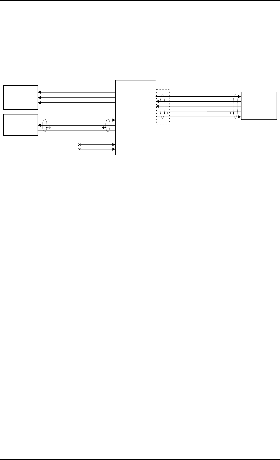
Electrical Installation and Wiring, HSU
5-78 Chapter 5: Installation TT98-113625-D
5.4.5 Wiring HSU to Discretes and Maintenance PC
Interface
The following drawing shows the wiring of the front maintenance interface and
discretes and RS-232 PC connection.
Maintenance Interface
The HSU has two RS-232 PC interfaces for maintenance, one at the front panel
connector and one at the rear panel connector. Both interfaces support the
EIA/TIA-232-E standard and may also be used as a printer interface.
Both interfaces may be used for software upload.
The interfaces are configured as DCE on the HSU (i.e. TxD is input and RxD is
output).
Front Maintenance Connector Interface EIA/TIA-232-E (FP2, FP3, FP5)
For information on pin-out for the Front Maintenance Connector interface, see
Pin-out for HSU Front Connector on page 4-14.
The Front Maintenance Connector Interface has the following characteristics:
• Baud rate: 115.2 kbit/s fixed
• Data bits: 8
• Parity: None
• Stop bit: 1
• Flow control: None
Figure 5-37: Wiring HSU to Discretes and RS-232 PC Maintenance Interfaces
TT-5038A
HSU
Maintenance
PC #2
TP6
TP7
TP5
Rear TxD (EIA/TIA-232-E)
Rear GND (EIA/TIA-232-E)
Rear RxD (EIA/TIA-232-E)
ATE #1 [1] TP9
TP10
Discrete
Outputs
ISDN Available
MPDS Available
HSU Failure TP27
TP28
TP29
ATE #2 [1]
FP2
FP3
FP4
FP5
FP6
Maintenance
PC #1
FRONT CONNECTOR (DB9)
[1] ATE is for test purpose only; leave unconnected
2
3
4
5
6
Front GND (EIA/TIA-232-E)
+12 VDC (to pull up FP4, DSR)
Disable Input for Rear I/F (DTR)
Front RxD (EIA/TIA-232-E)
Front TxD (EIA/TIA-232-E)
3
2
5
DB9F
DB9F

Electrical Installation and Wiring, HSU
TT98-113625-D Chapter 5: Installation 5-79
5555
Disable input for the Rear Maintenance Connector Interface (FP4)
The front panel connector contains an input pin to disable the Rear Maintenance
Connector Interface. The Rear Maintenance Connector Interface will be disabled when
the Front Maintenance Connector Interface is used, since the two interfaces share the
same internal serial I/O port.
The Rear Maintenance Connector Interface is disabled by connecting FP4 to +12V.
This can be done by mounting a jumper from FP4 to FP6 in the serial cable
connector. If a fully populated RS-232 serial cable is used, no jumper is needed.
FP4 corresponds to the RS-232 DTR signal, which is normally +12 V from the
PC-terminal.
FP4 is pulled down internally in the HSU to -12V with 15 kΩ.
+12 V DC for Front Maintenance Connector Interface (FP6)
FP6 provides a +12 V DC supply to pull up FP4 with a jumper as described above.
The +12 V DC is provided internally in the HSU with a 220 Ω pull up resistor
from FP6 to +12 V. FP6 corresponds to the RS-232 DSR signal.
Rear Maintenance Connector Interface EIA/TIA-232-E (TP5-TP7)
The following list shows the pins used for the Rear Maintenance Connector Interface.
The Rear Maintenance Connector Interface has the same characteristics as the Front
Maintenance Connector Interface. Also refer to Maintenance Interface on
page 5-78.
• Baud rate: 115.2 kbit/s fixed
• Data bits: 8
• Parity: None
• Stop bit: 1
• Flow control: None
HSU pin Name/Description
TP5 Rear Maintenance Connector Interface GND (EIA/TIA-232-E)
TP6 Rear Maintenance Connector Interface TxD Input (EIA/TIA-232-E)
TP7 Rear Maintenance Connector Interface RxD Output (EIA/TIA-232-E)
Table 5-46: HSU Pins for Rear Maintenance Connector Interface, RS-232

Electrical Installation and Wiring, HSU
5-80 Chapter 5: Installation TT98-113625-D
Discrete Inputs
The HSU has three discrete inputs, one for HSU Disable and two for ATE.
The ATE inputs are for test purpose only and must not be connected.
The HSU Disable input is described in HSU Disable (TP8) on page 5-67.
Discrete Outputs
The HSU has 3 discrete lamp driver outputs: HSU Failure, ISDN Available and
MPDS Available.
The output configuration forms a switch closure to ground.
The following list shows the pins used for the discrete lamp driver outputs.
The HSU Failure Discrete Output (TP27) is active whenever a BITE error with
the severity essential or fatal is active on the HSU.
The ISDN Available discrete output (TP28) is active when:
• The ISDN channel is actually in use, or
• The following conditions are all fulfilled:
- the HSU is ocean region registered
- no BITE error prohibits the ISDN service
- the current ISDN LES supports Swift64 ISDN
- the channel is not in use by MPDS
- power is available
The MPDS Available discrete output (TP29) is active when:
• The MPDS channel is actually in use, or
• The following conditions are all fulfilled:
- the HSU is ocean region registered
- no BITE error prohibits the MPDS service
- the current MPDS LES supports Swift64 ISDN
- the channel is not in use by ISDN
- power is available
Pin no (X2) Function Reference / Spec
TP27 HSU Failure Discrete Output Lamp type, active low
TP28 ISDN Available Discrete Output Lamp type, active low
TP29 MPDS Available Discrete Output Lamp type, active low
Table 5-47: HSU Pins for Discrete Outputs

Recommended Cables
TT98-113625-D Chapter 5: Installation 5-81
5555
5.5 Recommended Cables
5.5.1 Introduction
This section lists recommended cables and allowed cable lengths for the cables in
the Aero-HSD+ system.
Important! For specific requirements to the cables, see the applicable section in
5.3 Electrical Installation and Wiring or 5.4 Electrical
Installation and Wiring, HSU.
5.5.2 Power Cables, Allowed Cable Lengths
Allowed Cable Lengths, SDU
The following table shows the allowed SDU cable lengths for selected AWG
types. If other AWG types are used, make sure the contact type supports the AWG
type.
Note: It is generally recommended to keep cable lengths as short as possible,
specially on cables for Chassis GND.
Description Pin Contact
Type Max. resistance Max Length (at 70°C)
AW G 2 0 AW G 1 8 AW G 1 6 AW G 1 4
SDU
+28 V DC
Power
TP1 16 87.5 mΩ a
(200 mΩ-112.5 mΩ
in circuit breaker)
a. The max. cable resistance is calculated using the resistance of a Klixon 2TC circuit breaker. If
another circuit breaker is used, the max. resistance and cable length may differ from these values.
7ft
a
(2.1 m)
11 fta
(3.4 m)
18 fta
(5.4 m)
(not suitable
for this
contact size)
SDU
GND, Power
Return
TP2 16 25 mΩ2ft
(0.6 m)
3ft
(0.9 m)
5 ft
(1.5 m)
(not suitable
for this
contact size)
SDU Chassis
Ground
TP3 16 25 mΩ
(additional
requirement:
max. length 1 m)
2ft
(0.6 m)
3ft
(0.9 m)
3 ft
(1.0 m)
(not suitable
for this
contact size)
Table 5-48: Allowed Lengths for SDU Power Cables

Recommended Cables
5-82 Chapter 5: Installation TT98-113625-D
Allowed Cable Lengths, HPA
The following table shows the allowed HPA cable lengths for selected AWG
types. If other AWG types are used, make sure the contact type supports the AWG
type.
Note: It is generally recommended to keep cable lengths as short as possible,
specially on cables for Chassis.
Description Pin Contact
Type Max. resistance Max Length (at 70°C)
AW G 1 2 AW G 1 0 AW G 8
HPA
+28 V DC
Power
BP A1 5 87.5 mΩ a
(100 mΩ-12.5 mΩ
in circuit breaker)
a. The max. cable resistance is calculated using the resistance of a Klixon 2TC circuit breaker. If
another circuit breaker is used, the max. resistance and cable length may differ from these
values.
(not suitable for
this contact type)
71 fta
(21.6 m)
126 fta
(38.4 m)
HPA
GND, Power
Return
BP A2 5 25 mΩ(not suitable for
this contact type)
20 ft
(6.1 m)
36 ft
(11.0 m)
Table 5-49: Allowed Lengths for HPA Power Cables
Description Pin Contact
Type Max. resistance Max Length (at 70°C)
AW G 2 0 AW G 1 8
HPA Chassis BP30 20HD 25 mΩ2ft
(0.6 m)
(not suitable for
this contact size)
Table 5-50: Allowed Lengths for HPA Chassis Cable
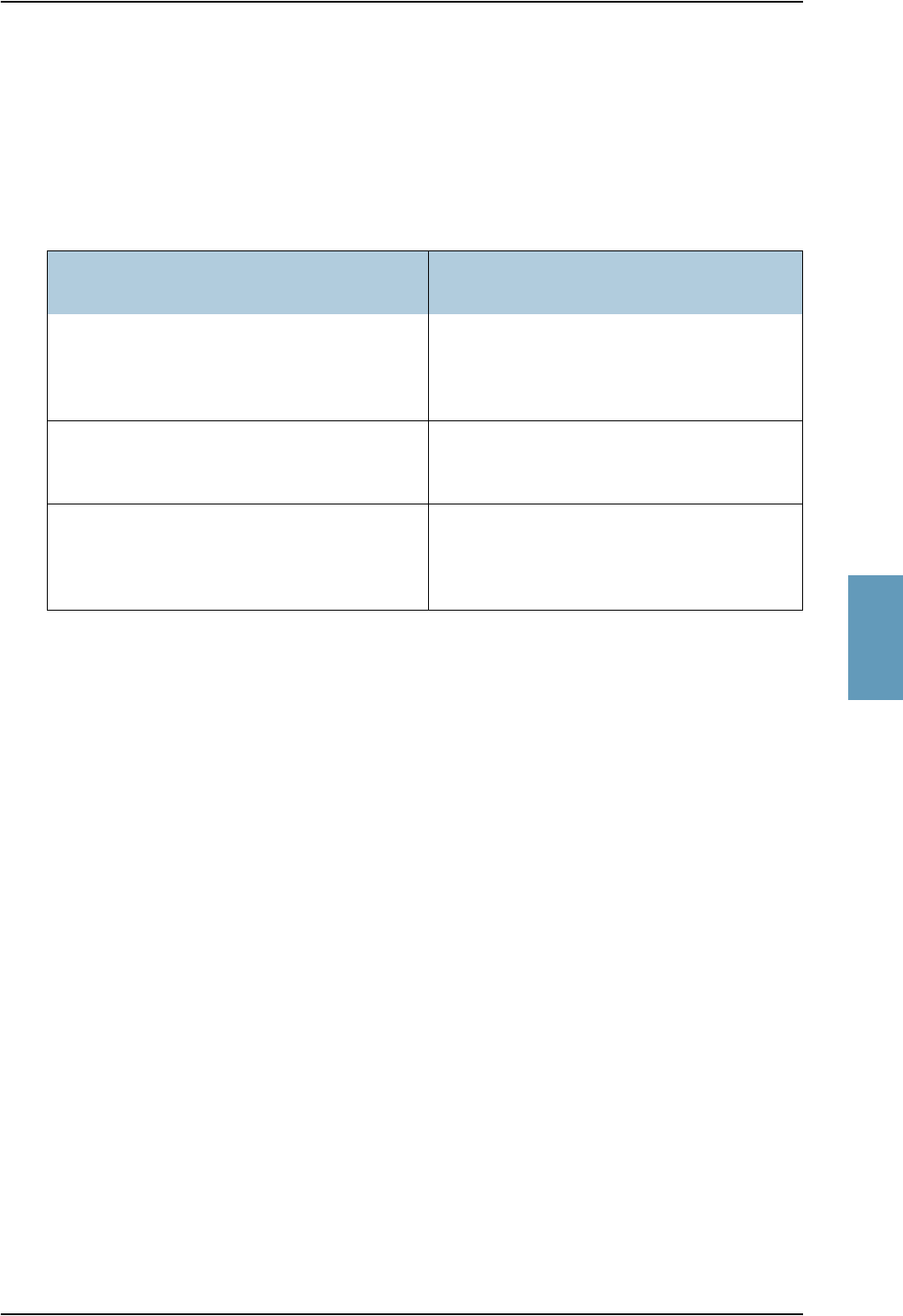
Recommended Cables
TT98-113625-D Chapter 5: Installation 5-83
5555
Allowed Cable Lengths, HSU
The following table shows the allowed HSU cable lengths for selected AWG
types. If other AWG types are used, make sure the contact type supports the AWG
type.
Note: It is generally recommended to keep cable lengths as short as possible,
specially on cables for Chassis GND.
Description Pin Contact
Type Max. resistance Max Length (at 70°C)
AW G 2 0 AW G 1 8 AW G 1 6 AW G 1 4
HSU
+28 V DC
Power
TP1 16 612.5 mΩ a
(725 mΩ-
112.5 mΩ in
circuit breaker)
a. The max. cable resistance is calculated using the resistance of a Klixon 2TC circuit breaker. If
another circuit breaker is used, the max. resistance and cable length may differ from these
values.
49 fta
(15.0 m)
79 fta
(24.0 m)
125 fta
(38.1 m)
(not suitable
for this
contact size)
HSU
GND, Power
Return
TP2 16 25 mΩ2ft
(0.6 m)
3ft
(0.9 m)
5 ft
(1.5 m)
(not suitable
for this
contact size)
HSU Chassis
Ground
TP3 16 25 mΩ
(additional
requirement:
max. length 1 m)
2ft
(0.6 m)
3ft
(0.9 m)
3 ft
(1.0 m)
(not suitable
for this
contact size)
Table 5-51: Allowed Lengths for HSU Power Cables

Recommended Cables
5-84 Chapter 5: Installation TT98-113625-D
5.5.3 Recommended RF Cables
The following cable types are recommended for the RF cables.
Note: Equivalent cable types, which meet the requirements, may also be used.
NOTE 1:
In some applications, RG 142 or RG 400 may be used where strict attenuation
requirements are not an issue. Cable specifications may vary depending on
manufacturer.
5.5.4 Recommended Cables for ARINC 429
The cables for the ARINC 429 interfaces must be twisted and shielded and
conform to the standards for aeronautical use.
The following cable types meet the requirements:
• Part number 422202, 22 Awg, from ECS
• Part number 422402, 24 Awg, from ECS
• Part number 522402, 24 Awg Hi-Tensile (Gulfstream), from ECS
• Part number F 2703-48-U AG from Draka Fileca
• Part number D620224 from PIC Wire and Cable
• Part number D771553 from PIC Wire and Cable
CABLE TYPE SPECIFICATIONS
Part Number Diameter
(mm/ in.)
Minimum
Bend Radius
(mm/ in.)
Attenuation
(dB/100ft)
@ 1.6 GHz
RG 142/400 NOTE 1 NOTE 1 Approx. 18.0
PIC S22089 11.0 / 0.43 63.5 / 2.5 4.8
PIC S33141 6.9 / 0.27 35.6 / 1.4 8.6
ECS 310801 11.48 / 0.452 57.4 / 2.26 4.6
ECS 311201 8.05 / 0.317 40.6 / 1.6 6.7
ECS 311501 5.82 / 0.229 30.5 / 1.2 9.1
EMTEQ TFLX165 100 4.19 / 0.17 21.6 / 0.85 16.8
EMTEQ TFLX295 100 7.95 / 0.31 40.6 / 1.6 7.9
EMTEQ TFLX480 100 12.2 / 0.48 57.2 / 2.25 4.5
Table 5-52: List of Recommended RF Cables

Recommended Cables
TT98-113625-D Chapter 5: Installation 5-85
5555
5.5.5 Recommended Cables for MPDS Ethernet
Cables for MPDS Ethernet on SDU (Quadrax Connector)
The cable for the MPDS Ethernet 10BaseT interface on the SDU must be a 100 Ω
4-wire twisted and shielded cable.
The following cable type meets the requirements:
• Part number 422404, Quadrax 24 Awg, from ECS
• Part number 922404, 10BaseT 24 Awg, from ECS
• Part number F 4704-4 from Draka Fileca
Cables for MPDS Ethernet on HSU (Twinax Connector)
The cable for the MPDS Ethernet 10BaseT interface on the HSU must be a 100 Ω
2-wire twisted and shielded cable.
The following cable types meet the requirements:
• Part number F 2703-37 from Draka Fileca
• Part number 41483-002-03 from Habia Cable

Commissioning
5-86 Chapter 5: Installation TT98-113625-D
5.6 Commissioning
5.6.1 Inmarsat Aeronautical Service & Solution Providers
After obtaining an Aero-HSD+ system, the owner must settle a contract with an
Inmarsat Aeronautical Service & Solution Provider who will handle terminal
activation, billing and technical support on the network side.
Inmarsat has divided Aeronautical Service & Solution Providers into 2 categories:
• Service Providers
• Solution Providers
Service Providers
Service Providers operate or have direct access to Inmarsat aeronautical Ground
Earth Stations. They supply the network capacity to the Solution Providers. The
services are particularly well-suited for airlines and large fleets of aircrafts.
An updated list of Service Providers is available here:
http://aero.inmarsat.com/how_to_buy/service_providers.aspx
Solution Providers
Solution Provider supply airtime packages, integration and installation expertise.
The services are particularly suited to corporate, VIP and government operators.
An updated list of Solution Providers is available here:
http://aero.inmarsat.com/how_to_buy/solution_providers.aspx

Commissioning
TT98-113625-D Chapter 5: Installation 5-87
5555
5.6.2 Activation
Administrative process
The activation is mainly an administrative process. The customer has to fill-in and
sign 2 documents:
• The Aeronautical SARF: The Service Activation Registration Form (SARF) is
the document required by Inmarsat for Service Activation. It includes
information such as the identity of the applicant, the type of equipment applied
for and the services required.
• The Provider subscription form: Some Service & Solution Providers require a
specific subscription form from the terminal owner.
Contact the providers for more details on this administrative process. They
provide the form for download on their website. Some also provide assistance in
filling in the documents.
When all the documents are signed, they must be sent by fax or mail to the chosen
provider. The activation can take from one day to one week, depending on the
provider and the country of registration.
Phone numbers and identifiers
When a terminal is activated, the terminal can be used on the network. The
terminal owner receives the phone numbers and identifiers:
• IMN (Inmarsat Mobile Numbers) on Swift64.
• DDI (Direct Dial-In) on Aero-H+.
• Direct phone number: to call the Aero-HSD+ terminal from the ground without
specifying the satellite region the terminal is located in (supported by a few
providers).
For information on how to make a call to the terminal, see Aero-HSD+ User
Manual, part number TT98-119959.

Verifying the Installation
5-88 Chapter 5: Installation TT98-113625-D
5.7 Verifying the Installation
Certain check procedures must be performed during and after installation of the
Aero-HSD+ system. The first check procedures are performed after wiring, but
before inserting LRUs.
For information on the required and recommended check procedures, see Check
procedures on page 7-1.

TT98-113625-D 6-1
Chapter 6
6666
Configuring the System 6
6.1 HSD+ Configuration Program
6.1.1 Overview
Configuration parameters from the SDU and HSU are stored in the Configuration
Module (CM), which is controlled using the HSD+ Configuration Program
(HSD+CP).
To access the CM and configure and store necessary operating parameters, a con-
figuration terminal consisting of a PC with the HSD+CP is used. The configura-
tion terminal makes it possible to:
• set up the system with all configurable parameters
• read, write and edit a complete set of operating parameters for the system
• save/load a configuration to/from a file
• import/export selected settings from/to a file
• print settings to a printer
• get help on specific topics through the Help menu, by pressing F1, or by using
the “What’s This?” button

HSD+ Configuration Program
6-2 Chapter 6: Configuring the System TT98-113625-D
6.1.2 Installation
Installation Requirements
•HSD
+CP Installation CD (Part number TT 83-119958-xxx, where xxx is the
software version).
• A PC running Windows® 95, Windows 98, Windows ME, Windows 2000,
Windows XP, or Windows NT systems.
Note: To use online help or to print settings, Internet Explorer 4.0 or greater is
required.
• 1024×768 or higher display resolution. The program is best viewed using small
fonts.
• Data Cable (Part number TT 37-112940 or equivalent).
• An available serial COM port (DB9) for the Data Cable.
Installation procedure
Locate and start the “setup.exe” file from the root directory on the HSD+CP
Installation CD and follow the instructions on screen.

HSD+ Configuration Program
TT98-113625-D Chapter 6: Configuring the System 6-3
6666
6.1.3 Description of HSD+CP
Navigation
The following picture shows the HSD+CP user interface.
The HSD+CP has a selection tree at the left side of the program window. Click
with the mouse or use the keyboard arrows up and down to select the scope of
interest. Then adjust the settings in the main window to the right.
Figure 6-1: HSD+CP User Interface
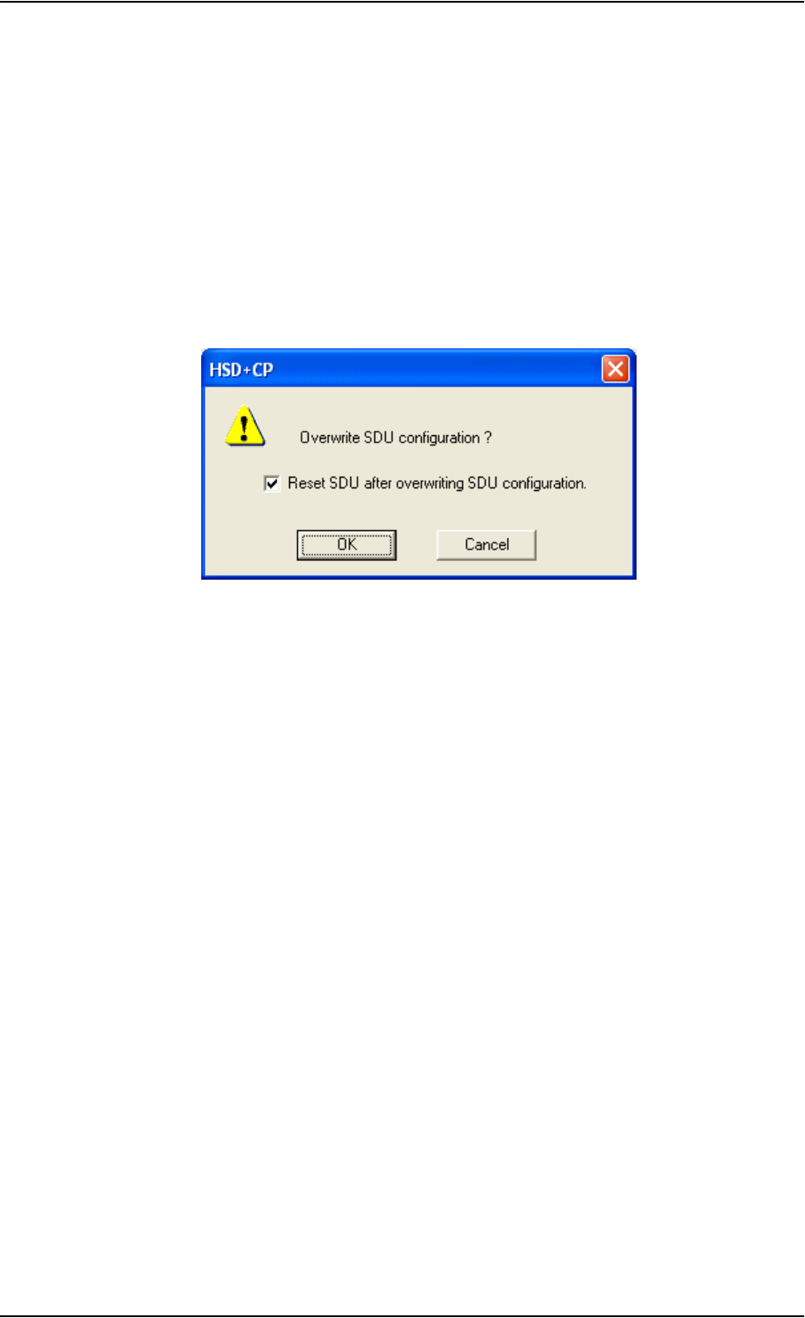
HSD+ Configuration Program
6-4 Chapter 6: Configuring the System TT98-113625-D
Applying Settings
There is no Apply function during a configuration session. When the view is
changed to another session, the settings entered in the first session are maintained.
• To apply all settings from the active session to the Aero-HSD+ system, click
the W button on the toolbar or select Write configuration to SDU from the
Link menu.
Note: Settings are only applied to the system after a reset. By default, the
option to automatically reset the SDU is enabled when a Write
operation is performed from the HSD+CP.
• Likewise, to read the settings from the SDU into the active session in the
HSD+CP, click the R button or select Read configuration from SDU from the
Link menu.
The configuration file can be created off-line (i.e. without an SDU connected to
the PC). The settings can then be transferred to the SDU at a later stage.
Before transferring the settings, connect the TT 37-112940 data cable between the
serial port of the PC and the front connector of the SDU. See Figure 5-27: TT 37-
112940 Data Cable Compliant with Front Connector.
A short description of each menu is provided in the following section.
Basic setup is described in the section Basic Configuration on page 6-6. For
further information on the HSD+ Configuration Program, please refer to the built-
in help system of the program.
Comparing Configurations
When comparing configurations, it can be useful to have two or more sessions
open at the same time.
The HSD+CP is a Multiple Document Interface (MDI) program. This means that
multiple (in this case four) configuration sessions can be open at the same time,
presented as tab pages. Switch between these sessions simply by selecting the tabs
or using the Windows menu on the Menu bar.

HSD+ Configuration Program
TT98-113625-D Chapter 6: Configuring the System 6-5
6666
6.1.4 Menu Overview
The HSD+CP comprises the following sub-items:
HSD+CP Configuration - start-up window
Satellite Network - setup of the conditions for logon to the satellite network,
including automatic/manual logon, setup of GESs for the H+ service and LESs
for the HSD service and initial satellite data.
Phone Book - a list of up to 100 phone numbers. From this window you can
add, edit and delete information in the phone book and assign quick-dial
numbers.
Information
•Versions etc. - shows
• the versions of the software installed in the SDU, the Handsets #1 through 4
and the Antenna.
• the PCB numbers of the individual boards in the system.
• the serial numbers of the LRUs in the system.
• the LRU Revision numbers of the SDU, the HPA and the antenna system.
• the build dates and the CRCs of the current builds.
•Identification - setup of ICAO address and ISN numbers.
Installation
•Handsets - setting of handset type, volume, ring tones etc. of the handsets in
the system.
•Ring Profiles - setup of ring profiles that each determine the behavior of all
handsets and annunciators.
•RF - setup of antenna and DLNA types, EIRP settings and RF cable losses.
•Ext. Systems - setup of external systems such as IRS/AHRS, CMU/ACARS,
MCDU/FMS etc.
•Date & Time - setup of date and time in the SDU and synchronization.
•BITE - List of BITE codes with the option to disable display of selected codes.
Tools
•Antenna Alignment - Point to a position on the map and view Azimuth and
Elevation.
•LAN - IP parameters for LAN connection. Under normal conditions, these
parameters should not be changed.

HSD+ Configuration Program
6-6 Chapter 6: Configuring the System TT98-113625-D
6.1.5 Basic Configuration
For detailed information on how to use the HSD+CP, please refer to the built-in
help system of the program (press F1 or use the Help menu).
Minimum Setup
As a minimum, you need to set up
•ICAO address.
In the navigation window of the HSD+CP, select Identification under
Information.
Then click the Copy button to copy the strapped ICAO address to the Config
Module, or type in the ICAO address in the Config Module field.
•Antenna type and heading.
Select RF under Installation and select the antenna type. Then enter the
Heading, Roll and Pitch offset.
•DLNA type and Diplexer loss.
In the RF window select the DLNA type and the Diplexer loss of the DLNA.
•Cable loss.
In the RF window, enter the cable losses in the Cable Loss fields.
•Navigation parameters, IRS/AHRS.
Select Ext. Systems under Installation.
Then select IRS or AHRS, select which interfaces are connected and whether
they run at low or high speed.
• Preferred LES and Logon Policy
Select ISDN or MPDS service and set up the list of preferred LESs.
Set H+ Logon Policy to Automatic or Manual.
•Handset parameters, Broadcast Ring Tone.
Select Handsets under installation. Then select a ring tone from the
Broadcast Ring Tone scroll list.
It is also recommended to set up
•Preferred GES.
Select Satellite Network and set up the list of preferred GESs.

HSD+ Configuration Program
TT98-113625-D Chapter 6: Configuring the System 6-7
6666
External Equipment
Depending on the connected equipment, it may be necessary to enter information
on some of the following items:
•Handsets.
Select Handsets under Installation.
Then enter which handset is installed on which interface and set the parameters
for each handset.
•Fax.
In the Handsets window, select Connected for the 2-wire interface that is
connected to a fax. This means the interface will not ring on a broadcast call.
•Ring Profiles.
Select Ring Profiles under Handsets. Set up one or more profiles that
determine which interfaces should ring when a broadcast call is received, and
which should not.
There are five possible profiles. One of them, “TakeOfLandng”, is preset and
cannot be changed. If the “Chime/Lamps Inhibit” input is activated, the
“TakeOfLandng” profile is automatically used. This input should be activated
during take-off and landing.
•CMU/ACARS/MCDU/FMS/WOW.
Select Ext. Systems under Installation.
Then enter which systems are connected and enter the requested parameters for
each system.

Configuration of 3rd Party Phone Systems
6-8 Chapter 6: Configuring the System TT98-113625-D
6.2 Configuration of 3rd Party Phone
Systems
6.2.1 MagnaStar
Some initial setup of the MagnaStar system is necessary for the system to work
properly.
Note: The information in this section is only meant as a guideline. For complete
information on the function and menus of the MagnaStar system, refer to
the MagnaStar manual.
To Set up the AIUs
Use the handset menus to set up the AIUs as follows:
1. Enter the Maintenance menu and navigate to the AIU SATCOM settings.
2. Set Impedance to High.
3. Set the mode to Handset.
To Assign the AIUs to the Handsets
When the AIUs are configured, air-to-ground calls can be made, but in order to be
able to make ground-to-air calls, an AIU must be assigned for each handset.
For each handset, enter the handset menu system and do as follows:
1. From the Maintenance menu, navigate to the Satcom Term ID setting.
2. Select Station and set the Terminal ID to 001 or 002.
To Set the Gain and Side Tone (Older Versions)
For some older versions of the MagnaStar system, each handset must be set up as
follows, in order to ensure correct operation:
1. From the Maintenance menu in the handset, navigate to the following
parameters and set them as specified:
• Typical Tx Gain: 070
• Side tone: 005

Configuration of 3rd Party Phone Systems
TT98-113625-D Chapter 6: Configuring the System 6-9
6666
6.2.2 Sigma7
There are a few adjustments that are typically made at the time of installation
testing. Normally it is necessary to set the ear volume of the handset initially, in
order to obtain sufficient volume in the ear piece.
Note: The information in this section is only meant as a guideline. For complete
information on the function of the Sigma7 handset, refer to the Sigma7
manual.
To Set up the Ear Volume
To set up the ear volume of the handset, do as follows:
1. Take the handset out of the cradle and enter the menu system.
2. Use the volume control keys to scroll to the EARVOL setting.
3. Press the Flash key to select EARVOL.
4. Change the volume setting to 4 using the volume control keys.
5. Press # to store the setting.
To adjust other settings, press Flash to return to the menu.
6. Place the handset back into the cradle.
For further information on the Sigma7 handset, refer to the manual for the Sigma7
handset.

Configuration of 3rd Party Phone Systems
6-10 Chapter 6: Configuring the System TT98-113625-D
6.2.3 2.4GHz Cordless
It is sometimes necessary to adjust the volume of the 2.4GHz Cordless handset, in
order to obtain sufficient volume in the ear piece. Also, the setting of the handset
might have to be changed from pulse to tone, if this is not already set.
Note: The information in this section is only meant as a guideline. For complete
information on the function of the 2.4GHz Cordless phone, refer to the
manual for your 2.4GHz Cordless phone.
Setting the Volume
To change the volume setting, enter the handset menus and do as follows:
1. Scroll to Audio Sett and press OK.
2. Select H/Set Vol and press OK.
The current volume is heard in the ear piece and the level is displayed.
3. Scroll to the desired volume and press OK.
To Switch to Tone Dialling
To change the dialling mode, do as follows:
1. Open the handset menu.
2. Scroll to Temp Tone and press OK.
Tone dialling is now active.

Basic Check Flow
TT98-113625-D Chapter 7: Check procedures 7-1
7777
Check procedures 7
7.1 Basic Check Flow
Important Note!
None of the check procedures described in this chapter can serve as a replacement
for any of the required approvals and certifications.
Check Procedures
In order to ensure the correct function of the system, the below check flow should
be followed.
1. Pre-Installation Check.
Perform this check after wiring, but before inserting the LRUs.
This is a check of the most important connections, the circuit breakers, cable
losses etc. Refer to Pre-Installation Check on page 7-2.
2. Configuration.
After performing the Pre-Installation Check, configure the system using the
HSD+ Configuration Program.
Refer to HSD+ Configuration Program on page 6-1, or consult the built-in
online help of the HSD+CP.
3. Functional Test, on Ground.
When the system is configured and commissioned, a functional test should be
performed. The functional test should check all user interfaces, such as voice,
fax, high speed data, annunciators, satcom on/off switch etc.
Refer to Functional Test, on Ground on page 7-4.
4. Interference Test.
After the functional test, an interference test should be performed. This test is
to verify that transmission from the Aero-HSD+ system has no effect on the
avionics of the aircraft, particularly navigation equipment.
Refer to Interference Test on page 7-5.
Note: If additional avionics are installed in the aircraft at a later stage, the
interference test should be performed again to ensure correct operation.
5. Functional Test, Airborne.
After the interference test, a functional test should be performed while the
aircraft is airborne. This test is basically the same as the functional test on
ground. Refer to Functional Test, Airborne on page 7-6.
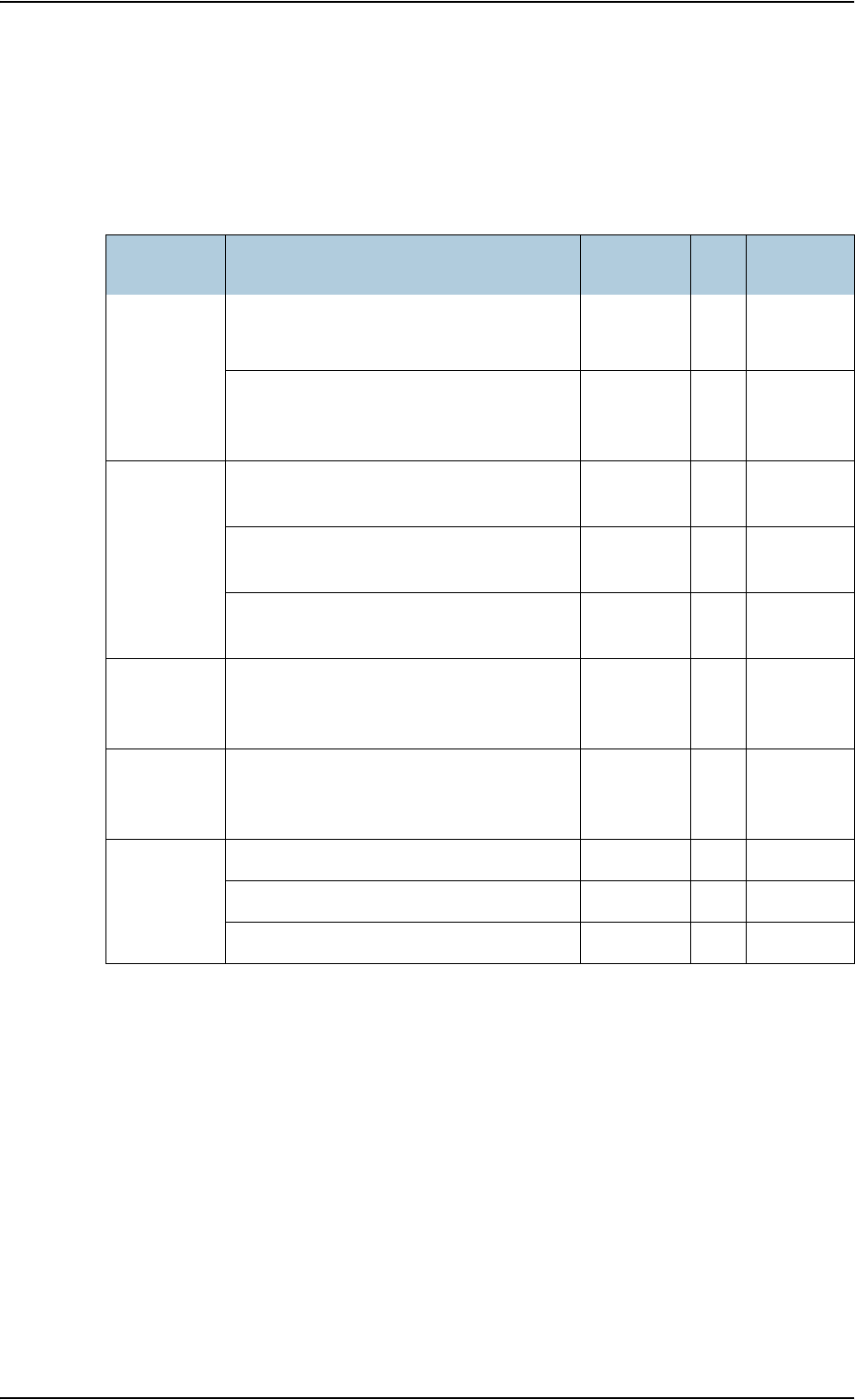
Pre-Installation Check
7-2 Chapter 7: Check procedures TT98-113625-D
7.2 Pre-Installation Check
It is recommended to check the installation before inserting LRUs. The following
list provides some of the most important issues, but other additional checks may
be relevant for the specific installation.
Item Description of Check Reference
Section √Val ue/
Comment
Mounting
trays
Ensure service/maintenance
accessibility.
5.2
Check that environmental
considerations are met
(Cooling, air-flow and pressure)
B.2
Coding of
tray
connectors
Check orientation of coding pins in SDU
tray connector
4.1.3
Check orientation of coding pins in HPA
tray connector
4.2
Check orientation of coding pins in HSU
tray connector
4.3.3
Quadrax
insert
orientation
Check that the Quadrax connector is
oriented correctly in the SDU tray
connector.
4.1.3
Grounding
stud
Check that the grounding stud on the
DLNA is connected correctly to aircraft
chassis.
Circuit
breaker
rating
Check the SDU circuit breaker: 4 A 5.3.2
Check the HPA circuit breaker: 20 A 5.3.2
Check the HSU circuit breaker: 4 A 5.4.2
Table 7-1: Check Sheet: Installation Check Before Inserting LRUs.
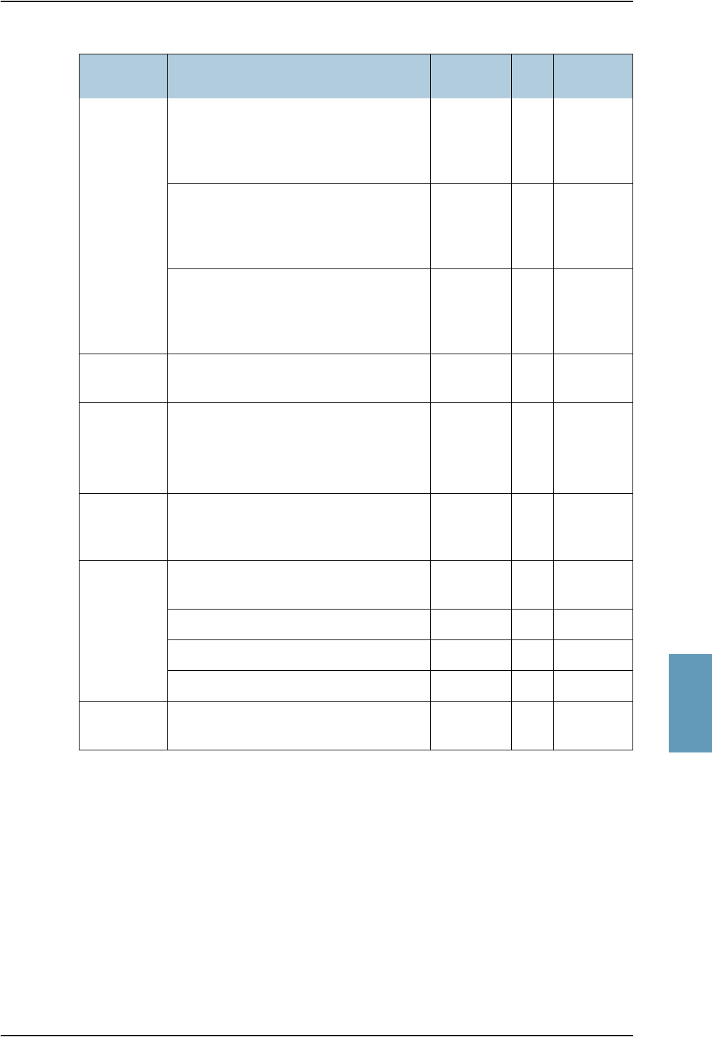
Pre-Installation Check
TT98-113625-D Chapter 7: Check procedures 7-3
7777
After a successful check of the installation, use the HSD+ Configuration Program
to configure the system. For further information, refer to HSD+ Configuration
Program on page 6-1, or the built-in help system of the HSD+CP.
Note: The cable loss values registered in the above table must be entered into
the HSD+ CP during configuration.
Polarity of
28 V DC
Power
Check 28 V DC polarity on SDU tray
connector
(TP1: +28 V DC Power and TP2: GND,
Power Return)
4.1.3
5.3.2
Check 28 V DC polarity on HPA tray
connector
(BPA1: +28 V DC Power and BPA2:
GND, Power Return)
4.2
5.3.2
Check 28 V DC polarity on HSU tray
connector
(TP1: +28 V DC Power and TP2: GND,
Power Return)
4.3.3
5.4.2
Handset
power
Check power to the handsets on DB15
connector to be inserted in cradle
5.3.8
4.4.2
nOn Check that TP5 (nOn) on the SDU
tray connector is connected to a
switch or directly to Chassis GND
(TP3).
5.3.2
4.1.3
Handset
connections
to Cradles
Check that 2-wire handsets are not
connected to 4-wire cradles.
RF cable
losses
Check loss from SDU to DLNA 5.3.3
6.1.5
Check loss from SDU to HPA
Check loss from HPA to DLNA
Check loss from DLNA to Antenna
Software
version
Check the software version of the SDU.
Item Description of Check Reference
Section √Value/
Comment
Table 7-1: Check Sheet: Installation Check Before Inserting LRUs.
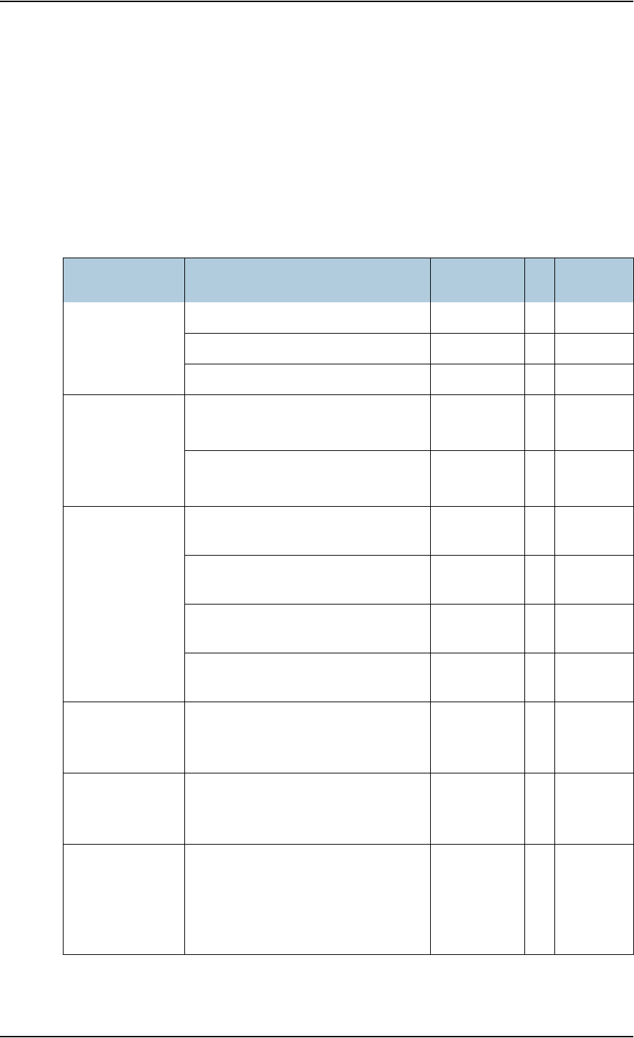
Functional Test, on Ground
7-4 Chapter 7: Check procedures TT98-113625-D
7.3 Functional Test, on Ground
Note: The system must be commissioned before performing this test. Refer to
Commissioning on page 5-86.
The following list provides some of the most important checks to perform after
power-up, but other additional checks may be relevant for the specific installation.
If any of the checks should fail, guidance is provided in the section Initial
Troubleshooting on page 8-11.
Item Description of Check Reference √Value/
Comment
SDU LEDs Check that the Power LED is green
Check that the Fail/Pass LED is green
Check that the Logon LED is green
Voice
handsets #1 to #6
Make an aircraft to ground call Aero-HSD+
User Manual
Make a ground to aircraft call Aero-HSD+
User Manual
Fax Send an H+ fax from aircraft to
ground
Aero-HSD+
User Manual
Send an H+ fax from ground to
aircraft
Aero-HSD+
User Manual
Send an HSD fax from aircraft to
ground
Aero-HSD+
User Manual
Send an HSD fax from ground to
aircraft
Aero-HSD+
User Manual
ISDN Connect to the internet from a
laptop, using the ISDN
connection.
Aero-HSD+
User Manual
MPDS (Ethernet) Connect to the internet from a
laptop, using the MPDS Ethernet
connection.
Aero-HSD+
User Manual
AFIS/ACARS Send test message and verify reply
or request for weather data and
verify the data is downloaded.
Both is done from the FMS. Refer
to FMS manual for more info.
FMS
Manual
Table 7-2: Check Sheet: Functional Test, on Ground

Interference Test
TT98-113625-D Chapter 7: Check procedures 7-5
7777
7.4 Interference Test
Introduction
It is recommended to perform an interference test to ensure that transmission from
the Aero-HSD+ system does not influence any of the primary avionics on the
aircraft.
Important! This test is not a replacement for any EMC tests in connection with
e.g. an STC, TC or Field Approval. It is only an additional practical
test of the application.
Test
During the test, the aircraft must be on ground. A skilled person should be
observing the instruments.
1. Log on to the satellite in the lowest possible elevation.
2. Place the aircraft in such a position that the satcom antenna transmits in the
direction of the other antennas on the aircraft.
Example: If the satcom antenna is tail-mounted, place the aircraft with the
nose pointing in the direction of the satellite. The antenna will then
transmit in the direction of the other antennas placed in front of it.
3. While transmission is ongoing, observe all primary navigation instruments,
autopilot, VOR/ILS, ADF and DME etc. and make sure none of the instruments
are influenced by the Aero-HSD+ transmission.
4. Monitor all VHF communication and make sure squelch is not opened
unintentionally.
5. If TCAS/ACAS is installed, verify that it is not flagged “FAILED” during
satcom transmission.
Note: If any additional avionics are installed at a later stage, the interference
test should be performed again.

Functional Test, Airborne
7-6 Chapter 7: Check procedures TT98-113625-D
7.5 Functional Test, Airborne
The following list provides some of the most important checks to perform while
the aircraft is airborne, after all on-ground tests are passed. Other additional
checks may be relevant for the specific installation.
If any of the checks should fail, guidance is provided in the section Initial
Troubleshooting on page 8-11.
Item Description of Check Reference √Value/
Comment
Voice Make an air to ground call and keep it
up during a 360º turn. Monitor the
C/No for any drops during the turn.
Aero-HSD+
User
Manual
Make a ground to air call Aero-HSD+
User
Manual
Fax Send an H+ fax from air to ground Aero-HSD+
User
Manual
Send an H+ fax from ground to air Aero-HSD+
User
Manual
Send an HSD fax from air to ground Aero-HSD+
User
Manual
Send an HSD fax from ground to air Aero-HSD+
User
Manual
ISDN Connect to the internet from a
laptop, using the ISDN
connection.
Aero-HSD+
User
Manual
MPDS
(Ethernet)
Connect to the internet from a
laptop, using the MPDS Ethernet
connection.
Aero-HSD+
User
Manual
AFIS/ACARS Send test message and verify reply
or request for weather data and
verify the data is downloaded.
Both is done from the FMS. Refer
to FMS manual for more info.
FMS
Manual
Table 7-3: Check Sheet: Functional Test, Airborne

TT98-113625-D 8-1
Chapter 8
8888
Maintenance and Troubleshooting8
8.1 Continued Airworthiness
8.1.1 General
Maintenance requirements and instructions for continued airworthiness of the
Thrane & Thrane units in the Aero-HSD+ System are restricted to the fact that the
TT-5035A Satellite Data Unit and the TT-5038A High Speed Data Unit require
replacement of an internal battery at a periodic scheduled service task of 7 years
(Overhaul). The Overhaul period is defined as the recommended period from
production date or last maintenance to next maintenance.
When replacing the TT-5035A Satellite Data Unit (SDU), it is important to leave
the TT-5035A-001 Configuration Module (CM) behind, attached to the airframe
with a wire.
8.1.2 Instructions
Documentation
Maintenance information for the Aero-HSD+ System is contained in this manual.
Wiring diagram information contained in this manual should be placed into the
aircraft operator's appropriate aircraft Wiring Diagram Manuals.
Inoperative Units
If a system component is inoperative, remove or replace the unit.
If an inoperative SDU is removed, take out the TT-5035A-001 Configuration
Module (CM) and fasten the CM and wiring. Secure all cables, collect applicable
switches and circuit breakers, and label them inoperative. Revise the equipment
list and weight and balance as applicable prior to flight and make a log book entry
that the unit was removed.
For information on how to return a unit for repair, see Returning Units for
Repair on page 8-15.
Once repaired, reinstall the LRU in the aircraft in accordance with the instructions
in this Installation and Maintenance Manual.

Continued Airworthiness
8-2 Chapter 8: Maintenance and Troubleshooting TT98-113625-D
Scheduled Maintenance Program
The high-speed data system components are considered on-condition units and no
additional maintenance is required other than a check for security and operation at
normal inspection intervals.
Scheduled Maintenance Program tasks to be added to the aircraft operator's
appropriate aircraft maintenance program are as follows:
Recommended Periodic Scheduled Servicing Tasks:
TT-5035A Satellite Data Unit (SDU) 7 years
TT-5038A High Speed Data Unit (HSU) 7 years
TT-5035A-001 Configuration Module (CM) none required
TT-5014A High Power Amplifier (HPA) none required
TT-5620A 4-Wire Handset none required
TT-5622A 4-Wire Cradle none required
TT-5621B 2-Wire Handset none required
TT-5622B 2-Wire Cradle none required

Continued Airworthiness
TT98-113625-D Chapter 8: Maintenance and Troubleshooting 8-3
8888
Recommended Periodic Inspections:
Recommended Periodic Scheduled Preventative Maintenance Tests:
(Tests to determine system condition and/or latent failures)
TT-5035A Satellite Data Unit (SDU) none required
TT-5038A High Speed Data Unit (HSU) none required
TT-5035A-001 Configuration Module (CM) none required
TT-5014A High Power Amplifier (HPA) none required
TT-5620A 4-Wire Handset none required
TT-5622A 4-Wire Cradle none required
TT-5621B 2-Wire Handset none required
TT-5622B 2-Wire Cradle none required

Software Update
8-4 Chapter 8: Maintenance and Troubleshooting TT98-113625-D
8.2 Software Update
Hardware and Software Requirements
The following items are required before the software can be updated:
• One IBM compatible PC with a 9-pin serial COM port available (or a 25-pin
serial COM port with a 25-to-9 converter attached)
• One serial interconnect cable 9-pin to 15-pin Sub-D, Thrane & Thrane part no.
TT-37-112940. Refer to Figure 5-27: TT 37-112940 Data Cable Compliant
with Front Connector.
• A terminal program installed on the PC (e.g. Windows HyperTerminal)
• An unzip program installed on the PC (e.g. WinZip)
• The zipped file containing the new software.
The new software can be obtained using www.tt.dk/aero/support.
Preparing the Software Update
Note: Software update is only allowed with a JAA/FAA145 approval
(Repair Station).
1. On the PC, unzip the zip file containing the new software.
2. Connect the SDU front port to the PC COM port, using the interconnect cable.
3. Set the terminal program baud rate to 115200 baud, No parity, 8 bit symbols.
4. Set the terminal transmission protocol to Xmodem-1K, binary transfer.

Software Update
TT98-113625-D Chapter 8: Maintenance and Troubleshooting 8-5
8888
Updating the Software
1. Assure that the terminal program communicates with the SDU by striking the
<Enter> key a couple of times. Each keystroke must cause the SDU to reply
with a prompt line 'H+>'.
2. Turn off the power for the SDU.
3. Using the terminal program, start transmission of the new file from the PC to
the SDU.
Note: The procedure for transmitting a file varies, depending on the terminal
program used. Refer to the instructions for the terminal program.
4. Power on the SDU.
When the file has finished transmission, the SDU will reset itself. Wait until the
POST test has finished (the green Pass/Fail LED on the front of the SDU will
become steadily green). The first self test after the software upload will take 4½
- 5 minutes (normally it takes 1½ - 2 minutes).
5. Mark the new software version on the SDU label.
Testing Procedure
To verify that the software was updated correctly, do as follows:
1. From the terminal program, issue the command:
version<enter>
2. On the resulting screen output, look for the 5th output line:
'Application SW version........... X.YY'
-where X.YY stands for the version number of the software.
3. Verify that the version number is correct.

Troubleshooting
8-6 Chapter 8: Maintenance and Troubleshooting TT98-113625-D
8.3 Troubleshooting
8.3.1 Status Signalling
Built-In Test Equipment
The SDU provides a Built-In Test Equipment (BITE) function in order to make
fault diagnostics easy during service and installation.
The BITE test is performed during:
• Power On Self Test (POST), which is automatically performed each time the
system is powered on.
• Person Activated Self Test (PAST), which is initiated by pressing the Push To
Test button on the SDU front panel.
Also, during operation a Continuous Monitoring BITE function is performed.
Each LRU in the Aero-HSD+ system has its own BITE function but they are all
controlled and monitored by the SDU in the system.
The result of the BITE tests for the complete Aero-HSD+ system is a four digit
error code. The two most significant digits represent the main group and are
displayed on the SDU front panel. The two least significant digits give further
details. All four digits are displayed in the user handset display together with more
detailed information.
Means of Signalling
The Aero-HSD+ system provides various methods for signalling the status of the
system.
•LEDs on the front panel of the SDU, optional HSU and the HPA are used to
signal:
• Power on/off
• Logon
•Fail/Pass
• The handset display in the Thrane & Thrane 4-wire handset is used to display
messages concerning:
• information from the services
• status information from the system to the user
• equipment errors.
• The BITE display on the SDU is used to display BITE error codes. Refer to
System Messages on page C-1.

Troubleshooting
TT98-113625-D Chapter 8: Maintenance and Troubleshooting 8-7
8888
Push to Test (PTT) button on SDU
The SDU has a hardware reset/test button placed on the front panel for BITE
purposes. This button is used to reset the SDU and to activate a self test (PAST).
LEDs on the SDU
Power LED
The function of the Power LED on the SDU is:
Logon LED (H+)
The Logon LED on the SDU shows the H+ logon status.
The HSD logon status is only signalled in the 4-wire handset.
The possible colors are listed below, with a short description of what they
indicate:
LED Color Description
Green Power OK
Orange Uploading software
Off No power
LED Color Description
Off No Acquired Satellite
Red Acquired a network satellite
Orange Network synchronization
Green Network Logon

Troubleshooting
8-8 Chapter 8: Maintenance and Troubleshooting TT98-113625-D
Fail/Pass LED, SDU
The function of the Fail/Pass LED on the SDU is:
LEDs on HPA
Power LED
The function of the Power LED on the HPA is:
Fail/Pass LED
The function of the Fail/Pass LED on the HPA is:
Behavior Description
Steady red Fail
Alternating:
Short green / long pause
Power On Self Test (POST) or Person
Activated Self Test (PAST) in progress.
Alternating:
Long green/ short orange 0.5 Hz
No current failure, but a BITE failure /
warning is logged in the error log
Steady green No faults
Behavior Description
Steady green Power OK
Off No power
Behavior Description
Steady red Fail
Off No Faults

Troubleshooting
TT98-113625-D Chapter 8: Maintenance and Troubleshooting 8-9
8888
LEDs on Optional HSU
Power LED
The function of the Power LED on the HSU is:
Fail LED
The function of the Fail LED on the HSU is:
Behavior Description
Steady green The unit is turned on and has completed
POST test.
Flashes 0.25 s out of every 4 s
(together with the red Fail LED –
see below)
The unit is turned on but is waiting for the
SDU (and has not yet started POST).
Flashes 0.5 s out of every 2 s. POST or PAST is in process.
Off No power.
Behavior Description
Steady red A fault which may degrade the system
operation is present in the HSU.
Flashing (together with the
Power LED – see above)
The unit is turned on but is waiting for the
SDU (and has not yet started POST).
Off Normal operation. No faults are present, and
the unit is no longer waiting for the SDU.

Troubleshooting
8-10 Chapter 8: Maintenance and Troubleshooting TT98-113625-D
Messages
Two types of messages are displayed in the Thrane & Thrane 4-wire handsets.
• Cause codes are information from the services or status information from the
system to the user.
• BITE codes are information about errors in the equipment.
BITE codes are also shown in the BITE display of the SDU and in the display of
the 4-wire handset.
For further information and lists of the possible error codes, see the appendix
System Messages on page C-1.
BITE Display on SDU
The two-digit 7-segment BITE display (green) is used for displaying BITE codes.
Only the two most significant digits of the four-digit BITE codes are shown in the
SDU display.
For further information and a list of the BITE codes, refer to BITE Error Codes
on page C-17.

Troubleshooting
TT98-113625-D Chapter 8: Maintenance and Troubleshooting 8-11
8888
8.3.2 Initial Troubleshooting
Overview
This section describes an initial check of the primary functions of the Aero-HSD+
system, and provides some guidelines for troubleshooting, if one of the checks
should fail.
Generally, if a fault occurs without any obvious reason, it is always recommended
to observe the LEDs and the BITE display.
For information on the function of the LEDs and the BITE display, refer to Status
Signalling on page 8-6.
For a list of all the BITE codes and Cause codes, refer to the appendix System
Messages on page C-1.
It may sometimes be necessary to use terminal commands for debugging, using
the front Maintenance port of the SDU.
For information on how to use the front port for debugging, see Using
Commands on page D-1.

Troubleshooting
8-12 Chapter 8: Maintenance and Troubleshooting TT98-113625-D
Check of LEDs
The below flow chart shows the initial check of the LEDs on the SDU, HPA and
HSU.
Figure 8-1: Initial Check of LEDs
Check:
yPower connections
yCircuit Breakers
ynOn input (TP5)
No
No
Check for error
codes in:
yBITE display
on SDU
yHandset
yMaintenance
port.
Set logon policy
to automatic or
log on manually
Check:
yLogon Cause code in handset (or maintenance port).
yHPA tray connector.
yHPA correct in tray.
yTx RF cable and connectors.
ySignal strength: Refer to the section about signal
strength in the User Manual. If low, check that the
antenna has line of sight to the satellite and that the
navigation data are correct.
yRx RF cable and connectors.
ySDU tray connector.
ySDU correct in tray.
yAntenna system incl. DLNA.
yIs ICAO address commissioned?
No
No
No
Check:
ySignal strength: Refer to the section about signal
strength in the User Manual. If low, check that the
antenna has line of sight to the satellite and that the
navigation data are correct.
yRx RF cable and connectors.
ySDU tray connector.
ySDU correct in tray.
yAntenna system incl. DLNA.
Yes
Yes
Yes
SDU Power LED
green?
SDU Fail/Pass LED
steady green?
SDU Logon
LED green?
Yes
Yes
Yes
Check:
yPower connections
yCircuit Breakers
ynOn input (BP6)
HPA Power
LED green?
Continue to:
Check of MPDS,
ISDN and Handsets
HPA related
BITE?
Check:
yPower connections
yCircuit Breakers
ynOn input (BP6)
HSU Power
LED green?
HSU related
BITE?
No
Yes
No
Yes
Troubleshoot
according to BITE
code. If you are unable
to resolve the issue,
call Thrane & Thrane
Customer Service.
No
Yes
Yes
No
Check:
yHPA correct in tray
ySDU to HPA RF cable
ySDU-HPA control signals
(SDU BP78-BP81 and
HPA BP25-BP28)
Check:
yHSU correct in tray
ySDU-HSU control
signals (SDU BP32-
BP35+BP56 and HSU
TP19-TP22+TP8)
Error found? No
SDU Logon
LED off?
SDU Logon
LED red?
SDU Logon
LED orange?

Troubleshooting
TT98-113625-D Chapter 8: Maintenance and Troubleshooting 8-13
8888
Check of MPDS, ISDN and Handsets
After checking the LEDs, the user functions should be checked.
The below flow chart shows the initial check of MPDS, ISDN and handsets.
Figure 8-2: Initial Check of MPDS, Fax, 4-Wire Handsets and ISDN
Continue to
Check of FAX.
Check:
yHSD logged on.
yPC to router connection has
link.
yPC has correct IP address.
yPC can ping router.
yRouter configuration.
Yes
No
No
MPDS working?
4-wire handsets
working?
Yes
Dialing?
Yes
No SDU LAN
Link?
No
Yes
Check:
yWiring between SDU Quadrax
connector and PC/router.
yRouter is powered.
Check:
yHSD ch signal strength > 54dB/Hz.
yPPPoE username/password.
yISN number is commissioned.
yCall release code on maintenance port.
No
ISDN DATA
working? Dialing?
Check:
yHSD ch signal strength > 54dB/Hz.
yPPP username/password (from service provider).
yISN number is commissioned.
yCall release code on maintenance port.
Yes
No
Check:
yHSD logged on.
yWiring between SDU (BP66-
69) and PC/Router.
If router installed, check:
yPC to router connection has
link.
yPC has correct IP address.
yPC can ping router
yRouter configuration.
2-wire handsets
working?
Internal
call OK
No
Air to
GND OK
GND to
air OK
No
No
Check:
yHandset plugged correctly into cradle.
yWiring from cradle to SDU.
yHandset configuration in HSD+CP.
Yes
Yes
Check:
yCall release code displayed in the handset
while making a call. Troubleshoot accordingly.
Check:
yDialed number is correct as shown on
activation form.
yHandset is not inhibited by flaps or slats.
yRouting is correct (ask your service provider).
Dialtone? No
Check:
yHandset plugged correctly into cradle.
yWiring from cradle to SDU.
No
Yes Check:
yError tone in handset when dialing.
yCall release code on maintenance port.
Data 2
(AFIS/ACARS)
working?
No System
"ready"
No
Check:
yConnection between SDU (BP41-45) and
CMU.
yConfiguration in HSD+CP. CMU/ACARS
marked "Connected" and correct speed
selected.
Yes
If handset shows "Circuit mode", your ICAO
number is not commisioned for DATA 2.
Note 1. HSD dial attempt can be seen as an increase in C/No of approximately 5-7 dB on the HSD channel.
Note 1.
Note 1.
Yes
Yes
Yes

Troubleshooting
8-14 Chapter 8: Maintenance and Troubleshooting TT98-113625-D
Check of Fax
The below flow chart shows the initial check of the fax interfaces.
Figure 8-3: Initial Check of Fax
Check OK
Yes
No
No
Check:
yConnection from fax "Line" to
SDU port 5 (TP19/6) or
6 (TP8/7)
Check:
yConnection to correct port on
SDU by dialing 5# or 6# from
a handset.
yRing Profiles correctly set up.
yService Provider has system
setup for "FAX on H+" and on
correct port (same as above).
Check:
yThe fax machine is set for
overseas mode.
yUse "00" as prefix.
yThe router uses "3.1KHz
audio" service.
Check:
yThe fax machine is set for
overseas mode.
yThe fax is set to pick up after
two or less rings.
Yes No
No
Yes
No
Yes
No
Yes
Fax working? Fax on H+? Dialtone?
Ringing?
Fax on
HSD?
Sending OK
(Air to GND)
Problems
receiving?
Check:
yThe fax machine is set for
overseas mode.
yUse "01" as prefix.
yFax startup transmit speed:
2400 bit/s (recommended).
Check:
yThe fax machine is set for
overseas mode.
yThe fax is set to pick up after
two or less rings.
yThe fax is in "FAX mode".
Yes
No
No
Sending OK
(Air to GND)
Receive OK
(GND to Air)
Yes
Check:
yHSD logged on.
yConnection from fax "Line" to
router or SDU.
yRouter works for ISDN data.
Check:
yService Provider has system
setup for "FAX on HSD".
No
No
Yes
Dialtone?
Ringing?

Returning Units for Repair
TT98-113625-D Chapter 8: Maintenance and Troubleshooting 8-15
8888
8.4 Returning Units for Repair
8.4.1 Return Material Authorization (RMA)
To return equipment to Thrane & Thrane for repair this RMA procedure must be
followed.
Failure to comply with this procedure may cause shipping delays and additional
charges.
Warranty Returns
Equipment that qualifies for warranty repair can be returned to Thrane & Thrane
for repair or replacement at our discretion. The customer is charged for the
shipping costs to Thrane & Thrane, and Thrane & Thrane will pay the shipping
costs to return the repaired/replaced unit to the customer.
Non-Warranty Returns
Equipment that fails to work properly because of improper or negligent use,
abuse, shipping damaged or any other condition can still be returned to Thrane &
Thrane for repair or replacement at our discretion.
The customer will be notified of the cost to repair or replace the unit before
invoicing for repair or replacement. The customer is charged for the shipping cost
to and from Thrane & Thrane.
Repackaging Requirements
An Aero-HSD+ unit must be returned to Thrane & Thrane in suitable ESD
secured shipping containers; failure to do so may invalidate the warranty.

Returning Units for Repair
8-16 Chapter 8: Maintenance and Troubleshooting TT98-113625-D
RMA Procedure
Before returning units to Thrane & Thrane for repair, please follow this procedure:
1. Have the following information ready before calling the Customer Service
Center:
• T&T Model number (example: TT405035A SDU).
• Serial number (example: 00443322).
• A thorough description of the fault.
• Aircraft serial number and/or tail number.
2. Call Thrane & Thrane Inc. Customer Service at: +1-757-463-9557 and ask
for Aero-HSD+ support.
3. Describe the fault as thoroughly as possible and ask for assistance. In some
cases, the error may be resolved over the phone.
4. If the unit has to be returned for repair, request an RMA number.
5. Request replacement/loan unit if required.
6. Pack the equipment or parts to be returned in approved shipping containers.
7. Write the RMA number on the outside of all shipping containers and ship to:
Thrane & Thrane Inc.
509 Viking Drive Suite
VA 23452 Virginia Beach
USA
Appendices A

TT98-113625-D A-1
Appendix A
AAAA
Equipment Specifications A
A.1 Introduction
Important Note!
The information, drawings, and wiring diagrams contained in this manual are
intended as a reference for engineering planning only. It is the installer’s
responsibility to compose installation drawings specific to the aircraft.
A.1.1 Total Weight of the Aero-HSD+ System
The total weight of the basic Thrane & Thrane units in an Aero-HSD+ system is:
26.04 lbs ± 1.21 lbs (11.78 kg ± 0.55 kg).
Note: Cables are not included.
The weight comprises the following units:
•TT-5035A SDU 7.72 lbs ±0.22 lbs (3.50 kg ±0.10 kg)
(incl. TT-5035A-001 CM)
• TT-5014A HPA 11.24 lbs ±0.44 lbs (5.10 kg ±0.20 kg)
•TT-5012A DLNA 5.8 lbs ±0.33 lbs (2.60 kg ±0.15 kg)
•TT-5620A Handset 0.68 lbs ±0.11 lbs (0.31 kg ±0.05 kg)
•TT-5622A Cradle 0.60 lbs ±0.11 lbs (0.27 kg ± 0.05 kg)

Aero-HSD+ System Components
A-2 Appendix A: Equipment Specifications TT98-113625-D
A.2 Aero-HSD+ System Components
A.2.1 TT-5035A Satellite Data Unit (SDU)
Specification with TT-5035A-001 Configuration Module (CM) mounted.
Characteristics Specification
Dimensions
(L x W x H)
ARINC 404A 3/8 ATR short, 3 MCU
12.62” x 7.62” x 3.56”
(320.5 mm x 193.5 mm x 90.4 mm)
Weight 7.72 lbs ±0.22 lbs (3.5 kg ±0.1 kg)
incl. Configuration Module
Mounting Mount in an ARINC 404A 3/8 ATR short tray in a
temperature controlled location.
Forced cooling is not recommended.
Supply Voltage
Power Hold-up
Nominal: +28.0 V DC
Voltage range
continuous operation: +20.5 V DC to 32.2 V DC
short time operation: +18.0 V DC to 32.2 V DC
5 ms. fully operational, 200 ms. Power Save Mode.
Power Consumption Max. 48 Wa, typ. 30 W.
a. Includes 4 x 4-wire handsets, 2 x 2-wire handsets, 4 ISDN phones and one TT-5012A
DLNA.
Connectors Rear: ARINC 404A
Front: SUB-D 15 Female.
Operating Temperature -25 ºC to +55 ºC
Altitude 55000 ft
Environmental Categories Refer to Environmental Qualification form in the
appendix DO-160C/D Specifications on page B-1 in this
manual.
Table A-1: General Specifications for SDU

Aero-HSD+ System Components
TT98-113625-D Appendix A: Equipment Specifications A-3
AAAA
A.2.2 TT-5014A High Power Amplifier (HPA)
Characteristics Specification
Dimensions
(L x W x H)
ARINC 404A 3/8 ATR short, 3 MCU
12.62” x 7.79” x 3.66”
(320.5 mm x 193.5 mm x 93.0 mm)
Weight 11.24 lbs ±0.44 lbs (5.1 kg ±0.2 kg)
Mounting Can be installed in a non-temperature controlled location.
The HPA is designed with built-in forced cooling. Do not
block the cooling air holes. Minimum clearance top and
bottom: 1” (25 mm)
Mount in ARINC 404A 3/8 ATR short tray with oval cut-
out as shown in Figure 3-12: Outline Drawing: Tray for
SDU and HPA..
Supply Voltage
Power Hold-up
Nominal: +28.0 V DC
Voltage range,
continuous operation: +20.5 V DC to 32.2 V DC
short time operation: +18.0 V DC to 32.2 V DC
5 ms. fully operational, 200 ms. Power Save Mode.
Power Consumption Max. 200 W, Absolute max. 235 W incl. Chelton HGA-
7000 antenna.
Composite Output Power 37.4 W (Burst Mode)
30.0 W (Continuous Mode)
Connectors Rear: ARINC 404A
Operating Temperature -55 ºC to +70 ºC
Altitude 55000 ft
Environmental Categories Refer to Environmental Qualification form in the
appendix DO-160C/D Specifications on page B-1 in this
manual.
Table A-2: General Specifications for HPA

Aero-HSD+ System Components
A-4 Appendix A: Equipment Specifications TT98-113625-D
A.2.3 TT-5012A Diplexer Low Noise Amplifier (DLNA)
Characteristics Specification
Dimensions (L x W x H) 10.58” x 7.64” x 1.95”
(268.8 mm x 194.0 mm x 49.5 mm)
Weight 5.8 lbs ±0.33 lbs (2.6 kg ±150 g)
Mounting Should be mounted as close to the Antenna unit as
possible.
Place the DLNA with sufficient contact to the surface,
respecting the max. resistance of 3 mΩ.
The DLNA can be mounted on a shelf or directly on the
fuselage. If the DLNA is mounted directly on fuselage,
mount with Cadmium plated washers.
Make sure the ground stud is connected to fuselage.
Supply Voltage +12 V DC, provided by SDU via coaxial cable.
Short circuit protected.
Power Consumption Max. 1.6 W (included in SDU power consumption).
Operating Temperature -55 ºC to +70 ºC
Altitude 55000 ft
Environmental Categories Refer to Environmental Qualification form in the
appendix DO-160C/D Specifications on page B-1 in this
manual.
Table A-3: General Specifications for DLNA

Aero-HSD+ System Components
TT98-113625-D Chapter A: Equipment Specifications A-5
AAAA
A.2.4 TT-5038A High Speed Data Unit (HSU)
Characteristics Specification
Dimensions
(L x W x H)
ARINC 404A 1/4 ATR short, 2 MCU
12.62” x 7.62” x 2.25”
(320.5 mm x 193.5 mm x 57.2 mm)
Weight 4.63 lbs ±0.22 lbs (2.1 kg ±100 g)
Mounting Mount in an ARINC 404A 1/4 ATR short tray in a
temperature controlled location.
Forced cooling is not recommended.
Supply Voltage
Power Hold-up
Nominal: +28.0 V DC
Voltage range,
continuous operation: +20.5 V DC to 32.2 V DC
short time operation: +18.0 V DC to 32.2 V DC
5 ms. fully operational, 200 ms. Power Save Mode.
Power Consumption Max. 23 Wa, typ. 13 W.
a. The ISDN terminals connected to the ISDN interface are assumed to consume
maximum 4.5 W.
Connectors Rear: ARINC 404A
Front: SUB-D 9 Female.
Operating Temperature -25 ºC to +55 ºC
Altitude 55000 ft
Environmental Categories Refer to Environmental Qualification form in the
appendix DO-160C/D Specifications on page B-1 in this
manual.
Table A-4: General Specifications for HSU

Aero-HSD+ System Components
A-6 Chapter A: Equipment Specifications TT98-113625-D
A.2.5 TT-5038A-002 Tx Coupler for Optional HSU
Characteristics Specification
Dimensions
(L x W x H)
ARINC 404A 1/4 ATR short, 2 MCU
4.20” x 2.25” x 0.88”
(106.6 mm x 57.1 mm x 22.4 mm)
including connectors.
Weight 0.50 lbs ±0.02 lbs (230 g ±10 g)
Mounting Can be mounted in an unpressurized but temperature
controlled location.
Connectors 3 x N-connector, Female.
Operating Temperature -25 ºC to +55 ºC
Altitude 55000 ft
Environmental Categories Refer to Environmental Qualification form in the
appendix DO-160C/D Specifications on page B-1 in this
manual.
Table A-5: General Specifications for Tx Coupler

Aero-HSD+ System Components
TT98-113625-D Chapter A: Equipment Specifications A-7
AAAA
A.2.6 TT-5038A-003 Rx Power Splitter for Optional HSU
Characteristics Specification
Dimensions
(L x W x H)
ARINC 404A 1/4 ATR short, 2 MCU
3.42” x 2.00” x 0.75”
(86.8 mm x 50.8 mm x 19.1 mm)
including connectors.
Weight 0.32 lbs ±0.02 lbs (146 g ±10 g)
Mounting If the Rx Power Splitter is to be mounted on a flat surface,
mount it on a 3 mm mounting plate to provide enough
space for mounting of the connectors.
Can be mounted in an unpressurized but temperature
controlled location.
Connectors 3 x N-connector, Female.
Built-in DC-block on the HSU port.
Operating Temperature -25 ºC to +55 ºC
Altitude 55000 ft
Environmental Categories Refer to Environmental Qualification form in the
appendix DO-160C/D Specifications on page B-1 in this
manual.
Table A-6: General Specifications for Rx Power Splitter

Aero-HSD+ Handsets and Cradles
A-8 Chapter A: Equipment Specifications TT98-113625-D
A.3 Aero-HSD+ Handsets and Cradles
A.3.1 TT-5620A 4-Wire Handset
Characteristics Specification
Dimensions (L x W x H) 7.87” x 2.05” x 1.24”
(200.0 mm x 52.0 mm x 31.5 mm)
Weight 0.68 lbs ±0.11 lbs (0.31 kg ±50 g) incl. cable.
Mounting Mount in a pressurized and temperature controlled
location.
Supply Voltage +28 V DC, provided by SDU via Handset Cradle.
Power Consumption Max. 3.5 W for handset and cradle (included in SDU
power consumption).
Operating Temperature -25 ºC to +55 ºC
Altitude 55000 ft
Environmental Categories Refer to Environmental Qualification form in the
appendix DO-160C/D Specifications on page B-1 in this
manual.
Table A-7: General Specifications for 4-Wire Handset

Aero-HSD+ Handsets and Cradles
TT98-113625-D Chapter A: Equipment Specifications A-9
AAAA
A.3.2 TT-5622A 4-Wire Cradle
Characteristics Specification
Dimensions (L x W x H) 6.30” x 2.40” x 1.12”
(160.5 mm x 61.0 mm x 28.4 mm)
Weight 0.60 lbs ±0.11 lbs (0.27 kg ±50 g) incl. connector cable.
Mounting Mount in a pressurized and temperature controlled
location.
Supply Voltage +28 V DC, provided by SDU.
Power Consumption See TT-5620A 4-Wire Handset on page A-8.
Operating Temperature -25 ºC to +55 ºC
Altitude 55000 ft
Environmental Categories Refer to Environmental Qualification form in the
appendix DO-160C/D Specifications on page B-1 in this
manual.
Table A-8: General Specifications for 4-Wire Cradle

Aero-HSD+ Handsets and Cradles
A-10 Chapter A: Equipment Specifications TT98-113625-D
A.3.3 TT-5621B 2-Wire Handset
Characteristics Specification
Dimensions (L x W x H) 7.87” x 2.05” x 1.24”
(200.0 mm x 52.0 mm x 31.5 mm)
Weight 0.49 lbs ±0.11 lbs (0.22 kg ±50 g) incl. cable.
Mounting Mount in a pressurized and temperature controlled
location.
Voltage
On hook, no load DC
Ringing voltage
20 V DC -10%, +50%
39 Vrms ± 5%
Off hook loop current 25 mA ± 15%
Power Max. 750 mW for handset and cradle (included in SDU
power consumption).
Operating Temperature -25 ºC to +55 ºC
Altitude 55000 ft
Environmental Categories Refer to Environmental Qualification form in the
appendix DO-160C/D Specifications on page B-1 in this
manual.
Table A-9: General Specifications for 2-Wire Handset

Aero-HSD+ Handsets and Cradles
TT98-113625-D Chapter A: Equipment Specifications A-11
AAAA
A.3.4 TT-5622B 2-Wire Cradle
Characteristics Specification
Dimensions (L x W x H) 6.30” x 2.40” x 1.12”
(160.5 mm x 61.0 mm x 28.4 mm)
Weight 0.43 lbs ±0.11 lbs (0.20 kg ±50 g)
incl. connector cable.
Mounting Mount in a pressurized and temperature controlled
location.
Voltage See TT-5621B 2-Wire Handset on page A-10.
Power See TT-5621B 2-Wire Handset on page A-10.
Operating Temperature -25 ºC to +55 ºC
Altitude 55000 ft
Environmental Categories Refer to Environmental Qualification form in the
appendix DO-160C/D Specifications on page B-1 in this
manual.
Table A-10: General Specifications for 2-Wire Cradle

Aero-HSD+ Handsets and Cradles
A-12 Chapter A: Equipment Specifications TT98-113625-D

TT98-113625-D B-1
Appendix B
BBBB
DO-160C/D Specifications B
B.1 General
B.1.1 Certifying Agency
Approval of the Aero-HSD+ system is not authorized by this installation manual.
Acceptance for the installation and use of the Aero-HSD+ system and its
associated components must be obtained through the appropriate offices of the
CAA or other certifying agency. It is recommended that all proposed installations
be coordinated with the local jurisdiction of the CAA or other certifying agency
prior to performing the installation.
B.1.2 Environmental Qualification Forms
The environmental qualification forms list the environmental categories under
which all Thrane & Thrane components of the Aero-HSD+ system are approved.
Please refer to RTCA DO-160C/D for further details on the following
environmental qualification forms.

Aero-HSD+ System Components
B-2 Appendix B: DO-160C/D Specifications TT98-113625-D
B.2 Aero-HSD+ System Components
B.2.1 Satellite Data Unit
T&T Part Number: 405035A
DO-160D string: [(A1)(F1)X]CAB[(S2B2)(SM)]EXXXXXZ[A()B]A[A()B]Z[RR]M[A3E3]XXA
RTCA/DO-160D Change Numbers
Change
Number Date of Issue Title Section
Change No. 1 Dec. 14, 2000 Vibration
Radio Frequency Susceptibility
8.0
20.0
Change No. 2 June 12, 2001 Power Input
Audio Frequency Conducted Susceptibility - Power Inputs
16.0
18.0
Table B-1: RTCA/DO-160D Change Numbers, SDU
Conditions DO-160D Cat. Comments
Temperature and Altitude 4.0 A1
and F1
Installation in controlled temperature
locations and inside or outside
pressurized locations.
Low Temperature 4.5.1 Min. operating low temperature: -25°C
High Temperature 4.5.2 & 4.5.3 Max. operating high temperature: +55°C
In-Flight Loss of Cooling 4.5.4 X Forced cooling is not recommended.
Altitude 4.6.1 Max. altitude: 55000 ft
Decompression 4.6.2 Decompression at 55000 ft
Overpressure 4.6.3 Overpressure at -15000ft
Temperature Variation 5.0 C Installation within controlled
temperature locations: 2°/min.
Humidity 6.0 A Standard Humidity: 95% relative
humidity at 38°C to 50°C for 48 hours.
Installation within environmentally
controlled zones.
Operational Shocks and Crash
Safety
7.0 B Equipment tested to: Standard
operational shocks and crash safety.
Table B-2: Environmental Qualification Form for SDU

Aero-HSD+ System Components
TT98-113625-D Appendix B: DO-160C/D Specifications B-3
BBBB
Vibration 8.0 S2B2
SM
Standard random vibration:
Aircraft type: Fixed wing. Turbojet or
turbofan engines.
Standard sinusoidal vibration:
Aircraft type: Fixed wing. Reciprocating
or turbopropeller engines.
Aircraft zone: Instrument panel, console
or equipment rack.
Explosion Proofness 9.0 E
Waterproofness 10.0 X No test required
Fluids Susceptibility 11.0 X No test required
Sand and Dust 12.0 X No test required
Fungus Resistance 13.0 X No test required
Salt Spray 14.0 X No test required
Magnetic Effect 15.0 Z Magnetic deflection distance: < 0.3 m
Power Input 16.0 A()B Power supply: +28 V DC.
Reconnection of voice and data calls is
not required, if a power interrupt less
than 200 ms occurs during transfer of
power sources.
Voltage Spike 17.0 A
Audio Frequency
Conducted Susceptibility -
Power Inputs
18.0 A()B
Induced Signal Susceptibility 19.0 Z Equipment intended for operation in
systems where interference-free
operation is required.
Radio Frequency Susceptibility 20.0 RR High Intensity Radiated Field (HIRF)
associated with normal environment.
Emission of Radio Frequency
Energy
21.0 M
Conditions DO-160D Cat. Comments
Table B-2: Environmental Qualification Form for SDU

Aero-HSD+ System Components
B-4 Appendix B: DO-160C/D Specifications TT98-113625-D
B.2.2 Configuration Module
T&T Part Number: 405035A-001
DO-160D string: Please refer to the section Satellite Data Unit on page B-2, as
the Configuration Module is an integral part of the SDU during normal operation
and tests.
Lightning Induced Transient
Susceptibility
22.0 A3E3 Equipment and wiring in moderately
exposed environment in an all metal
airframe.
The Configuration Module is an
integrated part of the SDU, and so the pin
injection tests are not required for the
Configuration Module interface.
Lightning Direct Effects 23.0 X No test required
Icing 24.0 X No test required
Electrostatic Discharge (ESD) 25.0 A Operation, installation and repair in an
aerospace environment.
Conditions DO-160D Cat. Comments
Table B-2: Environmental Qualification Form for SDU
Aero-HSD+ System Components
TT98-113625-D Appendix B: DO-160C/D Specifications B-5
BBBB
B.2.3 High Power Amplifier
T&T Part Number: 405014A
DO-160D string: [(A2)(F2)Z]BBB[SCL]EXXXXXZ[A()B]A[A()B]Z[RR]M[A3E3]XXA
RTCA/DO-160D Change Numbers
Change
Number Date of Issue Title Section
Change No. 1 Dec. 14, 2000 Vibration
Radio Frequency Susceptibility
8.0
20.0
Change No. 2 June 12, 2001 Power Input
Audio Frequency Conducted Susceptibility - Power Inputs
16.0
18.0
Table B-3: RTCA/DO-160D Change Numbers, HPA
Conditions DO-160D Cat. Comments
Temperature and Altitude 4.0 A2 and
F2
Installation in non-controlled
temperature locations and inside or
outside pressurized locations.
Low Temperature 4.5.1 Min. operating low temperature: -55°C
High Temperature 4.5.2 & 4.5.3 Max. operating high temperature: +70°C
In-Flight Loss of Cooling 4.5.4 Z Continuous operation at 40°C, tested
with internal fan turned off.
Use the recommended tray and leave at
least 1 inch (25 mm) of free space above
and below the HPA, to allow free
airflow.
The HPA is overheat protected.
External forced cooling is not
recommended.
Altitude 4.6.1 Max. altitude: 55000 ft
Decompression 4.6.2 Decompression at 55000 ft
Overpressure 4.6.3 Overpressure at -15000 ft
Temperature Variation 5.0 B Installation within non-temperature-
controlled location: 5°C/min.
Humidity 6.0 B Severe humidity: 95% relative humidity
at 38°C to 65°C for 240 hours.
Installation within non-environmentally
controlled zones.
Table B-4: Environmental Qualification Form for HPA

Aero-HSD+ System Components
B-6 Appendix B: DO-160C/D Specifications TT98-113625-D
Operational Shocks and Crash
Safety
7.0 B Equipment tested to: Standard
operational shocks and crash safety.
Vibration 8.0 SCL Standard sinusoidal and random
vibration:
Aircraft type: Fixed wing. Turbojet,
turbofan, reciprocating or turbopropeller
engines.
Aircraft zone: Fuselage
Explosion Proofness 9.0 E
Waterproofness 10.0 X No test required
Fluids Susceptibility 11.0 X No test required
Sand and Dust 12.0 X No test required
Fungus Resistance 13.0 X No test required
Salt Spray 14.0 X No test required
Magnetic Effect 15.0 Z Magnetic deflection distance: < 0.3 m
Power Input 16.0 A()B Power supply: +28 V DC.
Reconnection of voice and data calls is
not required, if a power interrupt less
than 200 ms occurs during transfer of
power sources.
Voltage Spike 17.0 A
Audio Frequency Conducted
Susceptibility - Power Inputs
18.0 A()B
Induced Signal Susceptibility 19.0 Z Equipment intended for operation in
systems where interference-free
operation is required.
Radio Frequency Susceptibility 20.0 RR High Intensity Radiated Field (HIRF)
associated with normal environment.
Emission of Radio Frequency
Energy
21.0 M
Lightning Induced Transient
Susceptibility
22.0 A3E3 Equipment and wiring in moderately
exposed environment in an all metal
airframe.
Lightning Direct Effects 23.0 X No test required
Icing 24.0 X No test required
Electrostatic Discharge (ESD) 25.0 A Operation, installation and repair in an
aerospace environment.
Conditions DO-160D Cat. Comments
Table B-4: Environmental Qualification Form for HPA

Aero-HSD+ System Components
TT98-113625-D Appendix B: DO-160C/D Specifications B-7
BBBB
B.2.4 Diplexer and Low Noise Amplifier
T&T Part Number: 405012A-THR
DO-160C string: [A2F2]-BA[CLY]XXXXXXA[AB]A[AB]Z[UR]ZA3E2XX
RTCA/DO-160C Change Numbers
Change
Number Date of Issue Title Section
Change No. 2 June 19, 1992 Lightning Induced Transient Susceptibility 22.0
Change No. 3 May 13, 1993 Radio Frequency Susceptibility 20.0
Table B-5: RTCA/DO-160C Change Numbers, DLNA
Conditions DO-160C Cat. Comments
Temperature and Altitude 4.0 A2 and
F2
Installation in non-controlled temperature
locations inside or outside pressurized
locations.
Low Temperature 4.5.1 Min. operating low temperature: -55°C
High Temperature 4.5.2 & 4.5.3 Max. operating high temperature: +70°C
In-Flight Loss of Cooling 4.5.4 - No forced cooling required.
Altitude 4.6.1 Max. altitude: 55000 ft
Decompression 4.6.2 Decompression at 55000 ft
Overpressure 4.6.3 Overpressure at -15000 ft
Temperature Variation 5.0 B Installation within partially or non-
controlled temperature locations: 5°C/min.
Humidity 6.0 A Standard Humidity: 95% relative humidity
at 38°C to 50°C for 48 hours.
Installation within environmentally
controlled zones
Operational Shocks and Crash
Safety
Operational Shock
Crash Safety
7.0
7.2
7.3
Yes
Yes
Yes
Equipment tested to: Standard operational
shocks and crash safety.
Table B-6: Environmental Qualification Form for DLNA

Aero-HSD+ System Components
B-8 Appendix B: DO-160C/D Specifications TT98-113625-D
Vibration 8.0 CL
Y
Standard sinusoidal and random vibration:
Aircraft type: Fixed wing. Turbojet,
turbofan, reciprocating or turbopropeller
engines.
Aircraft type: Helicopter. Turbojet or
reciprocating engines.
Aircraft Zone: Fuselage
Explosion Proofness 9.0 X No test required
Waterproofness 10.0 X No test required
Fluids Susceptibility 11.0 X No test required
Sand and Dust 12.0 X No test required
Fungus Resistance 13.0 X No test required
Salt Spray 14.0 X No test required
Magnetic Effect 15.0 A Magnetic deflection distance: 0.3 m to 1 m
Power Input 16.0 AB +12 V DC power is provided by the SDU
through the Rx coax cable.
Voltage Spike 17.0 A +12 V DC power is provided by the SDU
Audio Frequency Conducted
Susceptibility - Power Inputs
18.0 AB +12 V DC power is provided by the SDU
Induced Signal Susceptibility 19.0 Z Equipment intended for operation in
systems where interference-free operation
is required.
Radio Frequency
Susceptibility
20.0 UR
Emission of Radio Frequency
Energy
21.0 Z Equipment intended for operation in
systems where interference-free operation
is required.
Lightning Induced Transient
Susceptibility
22.0 A3E2 Equipment and wiring in moderately
exposed environment in an all metal
airframe.
Lightning Direct Effects 23.0 X No test required
Icing 24.0 X No test required
Conditions DO-160C Cat. Comments
Table B-6: Environmental Qualification Form for DLNA

Aero-HSD+ System Components
TT98-113625-D Chapter B: DO-160C/D Specifications B-9
BBBB
B.2.5 High Speed Data Unit (Optional)
T&T Part Number: 405038A
DO-160D string: [(A1)(F1)X]CBB[(S2B2)(SM)]EXXXXXZ[A()B]A[A()B]Z[RR]M[A3E3]XXA
For the environmental qualification form for the HSU, please refer to the section
Satellite Data Unit on page B-2, as the forms are identical for the SDU and the
HSU, except for:
Humidity, DO-160 section 6.0, tested to category B, Severe Humidity
Environment (240 hours, 65°C, 95% humidity).

Aero-HSD+ System Components
B-10 Chapter B: DO-160C/D Specifications TT98-113625-D
B.2.6 Tx Coupler and Rx Power Splitter for Optional HSU
T&T Part Numbers: 405038A-002 and 405038A-003
DO-160D string: [(A1)(F1)X]CBB[SCL]EXXXXXZXXXZ[RR]M[A3E3]XXA
RTCA/DO-160D Change Numbers
Change
Number Date of Issue Title Section
Change No. 1 Dec. 14, 2000 Vibration
Radio Frequency Susceptibility
8.0
20.0
Change No. 2 June 12, 2001 Power Input
Audio Frequency Conducted Susceptibility - Power Inputs
16.0
18.0
Table B-7: RTCA/DO-160D Change Numbers, Tx Coupler and Rx Power Splitter
Conditions DO-160D Cat. Comments
Temperature and Altitude 4.0 A1 and
F1
Installation in controlled temperature
locations and inside or outside
pressurized locations.
Low Temperature 4.5.1 Min. operating low temperature: -25°C
High Temperature 4.5.2 & 4.5.3 Max. operating high temperature: +55°C
In-Flight Loss of Cooling 4.5.4 X Forced cooling is not recommended.
Altitude 4.6.1 Max. altitude: 55000 ft
Decompression 4.6.2 Decompression at 55000 ft
Overpressure 4.6.3 Overpressure at -15000 ft
Temperature Variation 5.0 C Installation within controlled
temperature locations: 2°/min.
Humidity 6.0 B Severe humidity: 95% relative humidity
at 38°C to 65°C for 240 hours.
Installation within non-environmentally
controlled zones.
Operational Shocks and Crash
Safety
7.0 B Equipment tested to: Standard
operational shocks and crash safety.
Table B-8: Environmental Qualification Form for Tx Coupler and Rx Power Splitter
Aero-HSD+ System Components
TT98-113625-D Chapter B: DO-160C/D Specifications B-11
BBBB
Vibration 8.0 SCL Standard sinusoidal and random
vibration:
Aircraft type: Fixed wing. Turbojet,
turbofan, reciprocating or turbopropeller
engines.
Aircraft zone: Fuselage
Explosion Proofness 9.0 E
Waterproofness 10.0 X No test required
Fluids Susceptibility 11.0 X No test required
Sand and Dust 12.0 X No test required
Fungus Resistance 13.0 X No test required
Salt Spray 14.0 X No test required
Magnetic Effect 15.0 Z Magnetic deflection distance: < 0.3 m
Power Input 16.0 X No test required
Voltage Spike 17.0 X No test required
Audio Frequency Conducted
Susceptibility - Power Inputs
18.0 X No test required
Induced Signal Susceptibility 19.0 Z Equipment intended for operation in
systems where interference-free
operation is required
Radio Frequency
Susceptibility
20.0 RR High Intensity Radiated Field (HIRF)
associated with normal environment.
Emission of Radio Frequency
Energy
21.0 M
Lightning Induced Transient
Susceptibility
22.0 A3E3 Equipment and wiring in moderately
exposed environment in an all metal
airframe.
Lightning Direct Effects 23.0 X No test required
Icing 24.0 X No test required
Electrostatic Discharge (ESD) 25.0 A Operation, installation and repair in an
aerospace environment.
Conditions DO-160D Cat. Comments
Table B-8: Environmental Qualification Form for Tx Coupler and Rx Power Splitter

Aero-HSD+ Handsets and Cradles
B-12 Chapter B: DO-160C/D Specifications TT98-113625-D
B.3 Aero-HSD+ Handsets and Cradles
B.3.1 4-Wire Handset and 4-Wire Cradle
T&T Part Number: 405620A-THW / 405620A-THR / 405622A-THW / 405622A-
THR
DO-160C String: A1-BA[MNB]XXXXXXAXXXB[UR]ZXXE3XX
RTCA/DO-160C Change Numbers
Change
Number Date of Issue Title Section
Change No. 2 June 19, 1992 Lightning Induced Transient Susceptibility 22.0
Change No. 3 May 13, 1993 Radio Frequency Susceptibility 20.0
Table B-9: RTCA/DO-160C Change Numbers, 4-wire Handset and Cradle
Conditions DO-160C Cat. Comments
Temperature and Altitude 4.0 A1 Installation in controlled temperature and
pressurized location.
Low Temperature 4.5.1 Min. operating low temperature: -25°C
High Temperature 4.5.2 & 4.5.3 Max. operating high temperature: +55°C
In-Flight Loss of Cooling 4.5.4 - No forced cooling required.
Altitude 4.6.1 Max. altitude: 55000 ft
Decompression 4.6.2 Decompression at 55000 ft
Overpressure 4.6.3 Overpressure at -15000 ft
Temperature Variation 5.0 B Installation within partially or non-
controlled temperature locations: 5°C/min.
Humidity 6.0 A Standard Humidity: 95% relative humidity
at 38°C to 50°C for 48 hours.
Installation within environmentally
controlled zones
Operational Shocks and
Crash Safety
Operational Shock
Crash Safety
7.0
7.2
7.3
Yes
Yes
Yes
Equipment tested to: Standard operational
shocks and crash safety.
Table B-10: Environmental Qualification Form for 4-Wire Handset and Cradle

Aero-HSD+ Handsets and Cradles
TT98-113625-D Chapter B: DO-160C/D Specifications B-13
BBBB
Vibration 8.0 MB
N
Standard sinusoidal and random vibration:
Aircraft type: Fixed wing. Turbojet,
turbofan, reciprocating or turbopropeller
engines.
Aircraft type: Helicopter. Turbojet or
reciprocating engines.
Aircraft zone: Instrument panel, console or
equipment rack.
Explosion Proofness 9.0 X No test required
Waterproofness 10.0 X No test required
Fluids Susceptibility 11.0 X No test required
Sand and Dust 12.0 X No test required
Fungus Resistance 13.0 X No test required
Salt Spray 14.0 X No test required
Magnetic Effect 15.0 A Magnetic deflection distance: 0.3 m to 1 m
Power Input 16.0 X No test required. DC power is provided by
the SDU.
Voltage Spike 17.0 X No test required
Audio Frequency Conducted
Susceptibility - Power
Inputs
18.0 X No test required
Induced Signal
Susceptibility
19.0 B Installation where interference is controlled
to a tolerable level.
Radio Frequency
Susceptibility
20.0 UR
Emission of Radio
Frequency Energy
21.0 Z Equipment intended for operation in
systems where interference-free operation
is required.
Lightning Induced Transient
Susceptibility
22.0 XXE3 Cable Bundle Test: Equipment and wiring
in moderately exposed environment in an
all metal airframe.
Lightning Direct Effects 23.0 X No test required
Icing 24.0 X No test required
Conditions DO-160C Cat. Comments
Table B-10: Environmental Qualification Form for 4-Wire Handset and Cradle

Aero-HSD+ Handsets and Cradles
B-14 Chapter B: DO-160C/D Specifications TT98-113625-D
B.3.2 2-Wire Handset and 2-Wire Cradle
T&T Part Number: 405621B-THW / 405621B-THR / 405622B-THW / 405622B-
THR
DO-160D String: [A1X]CAB[(SMB2)(SM)(UFF1)]XXXXXXAXXXB[RRR]M[A2E3]XXA
RTCA/DO-160D Change Numbers:
Original DO-160D. Date of issue: July 29, 1997
Conditions DO-160D Cat. Comments
Temperature and Altitude 4.0 A1 Installation in controlled temperature and
pressurized location.
Low Temperature 4.5.1 Min. operating low temperature: -25°C
High Temperature 4.5.2 & 4.5.3 Max. operating high temperature: +55°C
In-Flight Loss of Cooling 4.5.4 X No forced cooling required.
Altitude 4.6.1 Max. altitude: 55000 ft
Decompression 4.6.2 Decompression at 55000 ft
Overpressure 4.6.3 Overpressure test at -15000 ft
Temperature Variation 5.0 C Installation within controlled temperature
locations: 2°/min.
Humidity 6.0 A Standard Humidity: 95% relative humidity
at 38°C to 50°C for 48 hours.
Installation within environmentally
controlled zones.
Operational Shocks and Crash
Safety
7.0 B Equipment tested to: Standard operational
shocks and crash safety.
Vibration 8.0 S2B2
SM
UFF1
Standard random vibration:
Aircraft type: Fixed wing. Turbojet or
turbofan engines.
Standard sinusoidal vibration:
Aircraft type: Fixed wing. Reciprocating
or turbopropeller engines.
Robust Sine-on-Random vibration:
Aircraft type: Helicopter. Turbojet or
reciprocating engines.
Aircraft zone: Instrument panel, console or
equipment rack.
Explosion Proofness 9.0 X No test required
Table B-11: Environmental Qualification Form for 2-Wire Handset and Cradle

Aero-HSD+ Handsets and Cradles
TT98-113625-D Chapter B: DO-160C/D Specifications B-15
BBBB
Waterproofness 10.0 X No test required
Fluids Susceptibility 11.0 X No test required
Sand and Dust 12.0 X No test required
Fungus Resistance 13.0 X No test required
Salt Spray 14.0 X No test required
Magnetic Effect 15.0 A Magnetic deflection distance: 0.3 m to 1 m
Power Input 16.0 X No test required
Voltage Spike 17.0 X No test required
Audio Frequency Conducted
Susceptibility
18.0 X No test required
Induced Signal Susceptibility 19.0 B Installation where interference is
controlled to a tolerable level.
Radio Frequency Susceptibility 20.0 RRR High Intensity Radiated Field (HIRF)
associated with normal environment.
Emission of Radio Frequency
Energy
21.0 M
Lightning induced Transient
Susceptibility
22.0 A2E3 Cable bundle test: Equipment and wiring
in moderately exposed environment in an
all metal airframe.
Lightning Direct Effects 23.0 X No test required
Icing 24.0 X No test required
Electrostatic Discharge (ESD) 25.0 A Operation, installation and repair in an
aerospace environment.
Conditions DO-160D Cat. Comments
Table B-11: Environmental Qualification Form for 2-Wire Handset and Cradle

Aero-HSD+ Handsets and Cradles
B-16 Chapter B: DO-160C/D Specifications TT98-113625-D

TT98-113625-D C-1
Appendix C
CCCC
System Messages C
C.1 Types of Messages
The Aero-HSD+ system announces messages in the 4-wire handset.
One type of messages is Cause codes, which are information from the satcom
services or status information from the system to the user.
Another type is BITE codes, which are information from the Aero-HSD+ system.
This information is a result of a POST or PAST sequence or Continuous
Monitoring performed by the Built-In Test Equipment.

Cause Codes
C-2 Appendix C: System Messages TT98-113625-D
C.2 Cause Codes
C.2.1 H+ Cause Codes
Logon Reject Cause Codes
Display Text ID Description Guidance
ClassReject 0x88 Class rejected The GES does not support this class.
GlobChanLoss 0x82 Global channel loss
GlobCunavlb 0x09 Global C channel not available
at GES
ManualLogRej 0x89 Manual login rejected Manual logon is not allowed when
logon policy is automatic.
NetworkFail 0x03 Network Failure
NoGesSignal 0x81 No GES signal
NoInitData 0x86 No valid system table available
NoSatSignal 0x80 No satellite signal Verify that there is no obstacle
between the Satellite and the AES
antenna.
NotAuthorizd AES not authorized Verify that the ICAO address used is
correct; if it is, contact the service
provider to verify that the ICAO
address is registered.
OtherReason 0x0E Other Reason
OutsideCover 0x84 Outside spot beam coverage The AES is not under a spot beam of
the specified GES.
P/R/Tunavlb 0x07 Packet data channel unavailable
PkdtaUnavlb 0x08 Packet data service unavailable
SDUfailure 0x8A SDU failure Check the current BITE errors.
SpotChanLoss 0x83 Spot channel loss
TableFull 0x00 Table Full
UserLogoff 0x87 User logoff
VCC&dUnavlb 0x0A Voice not available at GES
Table C-1: List of H+ Logon Reject Cause Codes

Cause Codes
TT98-113625-D Appendix C: System Messages C-3
CCCC
Call Reject Cause Codes
VoiceUnavlb 0x01 Voice Unavailable
WrongGES 0x85 GES not existing Check GES id validity.
WrongGESid 0x06 Wrong GES identifier Check GES id validity.
WrongParam 0x02 Wrong Parameter
WrongSatID 0x05 Wrong Satellite identifier Check satellite id validity.
Display Text ID Description Guidance
Table C-1: List of H+ Logon Reject Cause Codes
Display Text ID
(S-C-V)aDescription Guidance
0-1-0 Normal clearing
AddrComplete 1-0-1 Address complete
AESabsent 1-7-3 AES absent
AnalogFail 1-2-3 Analog data equipment not
available
AnalogRate 1-6-2 Required analog data rate not
supported
Busy 0-1-1 User busy
CallBared 1-4-3 Incoming calls barred
CallPreempt 1-1-1 Call pre-empted
CallRejected 0-1-5 Call rejected
CardInvalid 1-6-1 Credit card type not supported
CardRejected 1-3-1 Credit card number rejected
ChanAbsent 0-4-2 Channel type not implemented
DigitalFail 1-2-4 Digital data equipment not
available
DigitalRate 1-6-3 Required digital data rate not
supported
GndDestFail 0-1-11 Destination out of service
Table C-2: List of H+ Call Reject Cause Codes

Cause Codes
C-4 Appendix C: System Messages TT98-113625-D
Handover 1-7-4 Spot beam handover
InvalidAddr 1-3-2 Invalid/incomplete address
InvalidNumbr 0-1-12 Invalid number format
Network busy 1-5-1 Continuity failure One end of the line has
unexpectedly lost communication
with the other, in most cases
because the network is busy.
NetworkFail 0-2-6 Network Failure
NoAnswer 0-1-2 No user responding
NoChanAvail 1-2-1 No channel available
NoCircuit 0-2-2 No circuit/channel available
NoRoute 0-0-3 No route to destination
NoUnitAvail 1-2-2 No channel unit available Possible causes:
1. Both H+ voice channels are
already in use, and none of the
existing calls can be pre-empted.
2. Not enough EIRP to initiate a
call, and no other call can be pre-
empted.
3. All allocated H+ channels on
the GES are in use.
SatDestFail 1-4-1 Destination out of service
ServiceType 1-6-5 Service type not supported
SwitchBusy 0-2-10 Switching equipment
congestion
UnassignedNo 1-7-2 Unassigned number
Unauthorized 1-4-2 AES not authorized
Undefined 1-7-15 Undefined cause
Unspecified 0-1-15 Normal, unspecified
User Busy 1-7-1 User busy
VoiceTypeErr 1-6-4 Voice channel type not
supported
WrongNumber 0-0-1 Unassigned number
a. S=Coding Standard, C=Cause Class, V=Cause Value
Display Text ID
(S-C-V)aDescription Guidance
Table C-2: List of H+ Call Reject Cause Codes

Cause Codes
TT98-113625-D Appendix C: System Messages C-5
CCCC
C.2.2 MPDS Cause Codes
Layer 2 Reason Codes
L2 Reason
Number Interpretation
700 Reason Unspecified
701 L3 Release
702 L3 Deregister
703 L3 Reject
716 SAN Idle Timer Expiry
717 MAN Idle Timer Expiry
718 SAN Connect Timer
719 SAN Modify Timer
720 SAN Handover Timer
721 SAN Connection Timer
722 MAN Connection Timer
732 Insufficient operating system resources at MAN
733 Insufficient memory at MAN
748 Invalid L3 Call Ref in Establish SDU
749 Invalid L3 Call Ref in Modify SDU
764 Unsupported IPDS MAC version
765 Invalid Bearer Connection type in Establish SDU
766 Invalid Bearer Control type in Establish SDU
767 Invalid Bearer Connection ID in Establish SDU
768 Invalid Bearer Connection type in Modify SDU
769 Invalid Bearer Control type in Modify SDU
770 Invalid Bearer Connection ID in Modify SDU
771 Invalid Handover SDU
772 Invalid SDU type
Table C-3: List of MPDS Layer 2 Reason Codes

Cause Codes
C-6 Appendix C: System Messages TT98-113625-D
773 SDU Incorrectly Formatted
780 Connection sub-layer protocol failure (MAN specific signalling)
781 Connection sub-layer protocol failure (HDLC signalling)
796 Control sub-layer protocol failure
812 Channel Unit failure
813 Hardware failure
814 MAN not responding to frequency corrections
815 MAN not responding to power corrections
816 MAN not responding to timing corrections
828 Internal SAN failure
829 SAN Shutting Down
844 Bearer Control - No satellite link
845 Bearer Control - No suitable contention slot
846 Bearer Control - Status Acknowledgement failure
847 Bearer Control - Incorrect SAN ID
860 No such MAN
861 Invalid L3 Call Reference
L2 Reason
Number Interpretation
Table C-3: List of MPDS Layer 2 Reason Codes

Cause Codes
TT98-113625-D Appendix C: System Messages C-7
CCCC
Layer 3 Reason Codes
L3 Reason
Number Interpretation
500 Unknown Error
501 LES Access Code does not support IPDS
502 Network does not recognize Mobile ID
503 Network does not recognize SIM Card
504 Authentication Failed to Complete
505 Authentication Failure
506 Authorization Failure
507 Authorization Failure - Mobile Barred
508 Authorization Failure - Mobile Barred on this LES Access Code
509 Authorization Failure - SIM Card Barred on this LES Access Code
510 Authorization Failure - Temporarily Unable to Accept Credit Cards
511 Authorization Failure - Unable to Accept Credit Cards
512 Authorization Failure - Credit Card Refused
513 Authorization Failure - This Service not Allowed
514 Authorization Failure - Service Option(s) not Allowed
515 Authorization Failure - QoS not Allowed
516 Unsupported Service Option(s)
517 QoS Option(s) Unsupported by Mobile
518 QoS Option(s) Unsupported by Network
519 Satellite Network Congestion
520 Satellite Network Unavailable
521 Service Congestion
522 Service Unavailable
523 Terrestrial Network Congestion
524 Terrestrial Network Unavailable
525 Terrestrial Network Destination - Busy
Table C-4: List of MPDS Layer 3 Reason Codes

Cause Codes
C-8 Appendix C: System Messages TT98-113625-D
526 Terrestrial Network Destination - No Answer
527 Terrestrial Network Destination - Unavailable
528 Terrestrial Network Destination - No Carrier
529 Service Timed Out
530 Terminated by Network Operator
531 Insufficient Resources at Mobile
532 Mobile Failure
533 Mobile - Connection to DTE Lost
534 Mobile - Unrecoverable DTE Protocol Error
535 Mobile Reset
536 User Cancellation of Connection Establishment
600 Unable to Find Satellite Access Node
601 Unable to Establish Communication with Satellite Access Node
602 Link with Satellite Access Node Lost
1100 Registration Session Pre-empted by Host System
(Proprietary - not taken from IPDS System Definition Manual)
1101 Registration Session Pre-empted for Priority Call 1 by Host System
(Proprietary - not taken from IPDS System Definition Manual)
1102 Registration Session Pre-empted for Priority Call 2 by Host System
(Proprietary - not taken from IPDS System Definition Manual)
1103 Registration Session Pre-empted for Priority Call 3 by Host System
(Proprietary - not taken from IPDS System Definition Manual)
L3 Reason
Number Interpretation
Table C-4: List of MPDS Layer 3 Reason Codes

Cause Codes
TT98-113625-D Appendix C: System Messages C-9
CCCC
C.2.3 ISDN Cause Codes (SLCV)
The SLCV codes refer to: S = Coding Standard, L = cause Location, C = cause
Class, V = cause Value.
Code (Hex) Interpretation
S L C V
1 0 0 1 MES is clearing the call as instructed by the relevant MES terminal
equipment (i.e., normal clearing due to MES terminal “on-hook”
etc.).
1 0 1 1 MES is rejecting the call because the specified MES terminal number
is currently busy, and MES has not been authorized to divert calls
which are addressed to that number.
1 0 1 2 MES is clearing the fixed-originated call because subsequent to the
acceptance of the call and the signalling of the identity of the mobile
terminal to which the call will actually be routed, that terminal has
become busy and hence cannot be rung.
1 0 2 1 MES is clearing the call because appropriate “off-hook” signalling
has not been received from the addressed MES terminal (including
any authorized diversions) within the allowed time limit.
1 0 8 1 MES is rejecting the call because the specified MES terminal number
has not been installed, and MES has not been authorized to divert
calls which are addressed to that number.
1 0 9 1 MES is rejecting the call because the specified MES terminal number
is currently out-of-service, and MES has not been authorized to divert
calls which are addressed to that number.
1 0 9 2 MES is clearing the fixed-originated call because subsequent to the
acceptance of the call and the signalling of the identity of the mobile
terminal to which the call will actually be routed, that terminal has
become out-of-service and hence cannot be rung.
1 1 4 3 MES is prematurely clearing the fixed-originated call which is in the
process of being established because the MES user has initiated a call
from a terminal which is authorized to automatically pre-empt an
existing fixed-originated call.
1 1 4 4 MES is prematurely clearing the MES-originated call which is in the
process of being established because the MES user has initiated a
higher priority call.
1 1 4 5 MES is prematurely clearing the mobile-originated call which is in
the process of being established because the MES user has initiated a
call from a terminal which is authorized to automatically pre-empt an
existing mobile-originated call.
Table C-5: List of ISDN Cause Codes (SLCV)

Cause Codes
C-10 Appendix C: System Messages TT98-113625-D
1 1 4 6 MES is prematurely clearing the mobile-originated call which is in
the process of being established because the MES user has abandoned
the call (by placing the originating terminal “on-hook”).
1 1 D 1 LES is rejecting the call because the “Service Nature” and/or “Service
Type” and/or “Channel parameter” information received from the
MES is invalid (e.g., not currently defined in the SDM, mutually
contradictory, or not applicable to a MES originated call).
1 1 D 2 LES is clearing the call because the “service address” information
received from the MES is invalid (i.e., less than 2 digits).
1 1 D 3 LES is clearing the call because the “service address” information
received from the MES is a 2-digit address which is either undefined
or which is currently unavailable at this LES.
1 1 D 5 LES is clearing the call because the “service address” information
received from the MES contains a country code which is regarded (by
this LES) as invalid.
1 1 D 6 LES is clearing the call because the “PID” information received from
the MES in the “scrambling vector” message (type 8D H) is not
consistent with the PID information in the Fixed/MES Originated
(PID) and PID/MES Registration Tables at the LES as it relates to this
call.
1 2 0 2 (Spot Beam Handover): MES is ready to make the transition from the
current beam to the next beam.
1 2 8 1 MES is rejecting the call because the MES is not equipped to provide
the specified service.
1 2 9 1 MES is rejecting the call because although it is equipped to provide
the specified service, it is not currently able to do so.
1 2 B 1 MES is rejecting or clearing the call for a reason which is not covered
by any of the currently defined “Cause” events.
1 2 C 3 MES is clearing the call because a “LES Connect” message (type
8C H) has not been received by the MES within the allowed time
limit.
1 2 C 4 MES is clearing the call because the “authentication query” ISU
message (type B4 H) and/or the “authentication query” SSU message
(type B5 H) have not been received by the MES within the allowed
time limit.
1 2 C 5 MES is clearing the call because an expected supplementary services
SU(s) has (have) not been received by the MES within the allowed
time limit.
Code (Hex) Interpretation
S L C V
Table C-5: List of ISDN Cause Codes (SLCV)

Cause Codes
TT98-113625-D Appendix C: System Messages C-11
CCCC
1 2 C 6 MES is clearing the call because the “supplementary services
interrogation” ISU (type B2 H), and/or “subscriber digits” SSU (type
AD H) messages have not been received by the MES within the
allowed time limit.
1 2 C 7 MES is clearing the call because a “SCPC channel release” SU (type
8A H) has not been received by the MES, in response to the
transmission of a “notification acknowledge” message (type BA H)
during the supplementary services call diversion information retrieval
process, within the allowed time limit.
1 2 C 8 (Spot Beam Handover): MES is clearing the call session in the next
beam because the MES did not detect the LESH carrier on the new
frequency.
1 2 D 1 LES is rejecting the call because the “spot-beam ID” information
received from the MES is invalid (i.e., ID is not allocated on satellite
in use).
1 2 D 2 LES is clearing the call because the “Scrambling Vector” information
received from the MES is invalid (i.e., 0000H, 6959H or 7FFFH).
1 3 6 2 MES is clearing the call because a long-term interruption in reception
has occurred (the definition of a “long-term interruption” depends
upon the service type, see Section B).
1 3 6 3 A Secondary Functional Centre of a Multi-channel MES is clearing
the call because the Primary Functional centre has commanded the
Above-decks equipment to re-point to a different Ocean Region.
Note: The above text is specific to a Fleet system. However,
for the Aero HSD+ system this SLCV code is relevant
when the H+ sub-system is repointing the antenna from
one ocean region to another. That will cause the
Swift64 sub-system to be pre-empted with the SLCV
1363.
1 3 9 1 MES is clearing the call because the call has lasted more than 700 km
in linear travelled distance.
1 3 9 2 MES is clearing the call because it has moved out of spot beam
coverage.
1 3 9 3 MES in “cooperative mode” is clearing the call because of a pre-
emption request from the master entity.
1 4 5 1 LES is rejecting the call because an appropriate terrestrial circuit is
not currently available at this specific LES.
Code (Hex) Interpretation
S L C V
Table C-5: List of ISDN Cause Codes (SLCV)

Cause Codes
C-12 Appendix C: System Messages TT98-113625-D
1 4 5 2 LES is rejecting the call because an appropriate channel unit and
associated terrestrial circuit are not currently available at this LES.
[This “cause” is only utilized when there is a permanent “one-to-one”
connection between appropriate channel units and their terrestrial
circuits].
1 5 0 2 (Spot Beam Handover): LES is ready to make the transition from the
current beam to the next beam and is clearing the call session in the
current beam (normal clear).
1 5 5 1 LES is rejecting the call because an appropriate satellite channel is not
currently available at this specific LES.
1 5 8 1 LES is rejecting the call because the requested service is not provided
by this specific LES.
1 5 9 1 LES is rejecting the call because the requested service is temporarily
not available at this specific LES.
1 5 A 1 LES is rejecting the call because the specified MES is not authorized
for any service at this specific LES.
1 5 A 2 LES is rejecting the call because the specified MES is not authorized
to use specific requested service via this specific LES.
1 5 A 3 LES is clearing the call because the “credit card data” information
received from the MES has been rejected by the credit card
authorization process.
1 5 A 4 LES is clearing the call because the data received from the MES in the
“authentication reply” message (type B6 H) has been declared
“invalid” by the LES authentication process.
1 5 A 5 LES is rejecting the call because the specified PID is not authorized
for any service at this specific LES.
1 5 A 6 LES is rejecting the call because the specified PID is not authorized to
use specific requested service via this specific LES.
1 5 A 7 LES is clearing the call because the service address received from the
MES is not authorized for the requested priority.
1 5 B 1 LES is rejecting or clearing the call for a reason which is not covered
by any of the currently defined “Cause” events.
1 5 C 1 LES is rejecting the call because an appropriate “Channel
Assignment” message has not been received by the LES within the
allowed time limit.
Code (Hex) Interpretation
S L C V
Table C-5: List of ISDN Cause Codes (SLCV)

Cause Codes
TT98-113625-D Chapter C: System Messages C-13
CCCC
1 5 C 2 LES is clearing the call because the “service address” information has
not been received by the LES within the allowed time limit.
1 5 C 3 LES is clearing the call because a “Scrambling Vector” message (type
8D H) has not been received by the LES within the allowed time
limit.
1 5 C 4 LES is clearing the call because neither the “service address”
information nor a “Scrambling Vector” message (type 8D H) has
been received by the LES within the allowed time limit.
1 5 C 7 LES is clearing the call because a “MES Connect” message (type
99 H) has not been received by the LES within the allowed time limit.
1 5 C 9 LES is clearing the call because a “authentication reply” message
(type B6 H) has not been received by the LES within the allowed time
limit.
1 5 C A LES is clearing the call because a “notification acknowledge”
message (type BA H) has not been received by the LES within the
allowed time limit.
1 5 C B LES is clearing the call because the request sequence number
contained in the received “notification acknowledge” message (type
BA) is not valid (i.e. either not ‘0’ or not the next value in the
sequence).
1 5 C C (Spot Beam Handover): LES is terminating the procedure because it
did not receive a response to the Handover Request from the NCS.
1 5 C D (Spot Beam Handover): LES is clearing the call session in the next
beam because the MES did not indicate that it was ready to make the
transition (possibly because the MES did not receive the Channel
Assignment).
1 5 D 1 LES is rejecting the call because the “Channel Assignment” message
received from the NCS contains inappropriate or conflicting
information.
1 5 D 2 LES is clearing this MES ID and channel number in the busy lists at
LES and NCS because a new call to/from this MES is being set-up
(and thus any previous call to/from this MES must have cleared).
1 5 E 1 LES is attempting to clear an MES which has sent an SCPC channel
release message but is found still to be transmitting 5.12 s later.
1 6 5 1 LES is rejecting the call because an appropriate channel unit is not
currently available at this specific LES.
Code (Hex) Interpretation
S L C V
Table C-5: List of ISDN Cause Codes (SLCV)

Cause Codes
C-14 Chapter C: System Messages TT98-113625-D
1 6 6 1 LES is clearing the call because of an interruption in reception of the
MES carrier exceeding the allowed time limit.
1 6 C 2 LES is clearing the call because an appropriate SCPC MES carrier has
not been received by the LES (at the commencement of the call)
within the allowed time limit.
1 6 C 3 (Spot Beam Handover): LES is clearing the call session in the next
beam because the LES did not detect the MESH carrier on the new
frequency.
1 7 9 1 LES is clearing the call because of a malfunction in the authentication
checking database or in the communications links thereto.
1 8 1 1 NCS is rejecting the call because the specified MES ID is in the
“MES busy” list at the NCS.
1 8 1 2 NCS is rejecting the call because the specified MES is busy with an
IPDS call at the NCS.
1 8 1 3 NCS is rejecting the call because the specified MES is busy with an
IPDS call at the NCS, and the call waiting notification was declined
or timed out by the MES.
1 8 1 4 NCS is rejecting the call because the specified MES is busy with an
IPDS call at the NCS, and call waiting notification is unavailable.
1 8 5 1 NCS is rejecting the call because an appropriate SCPC channel is not
currently available.
1 8 5 2 NCS is rejecting the call because no SCPC channel exists at the NCS
which matches the contents of the Channel Parameters, Service
Nature, Service Type, MES Category, Spot Beam ID and Priority
fields contained in the Request for Channel Assignment.
1 8 5 3 NCS is rejecting the call because no SCPC channel is currently
available for the specified lease marked MES.
1 8 5 4 NCS is rejecting the call because the MES is outside the spot beam
coverage area.
1 8 5 5 NCS is rejecting the call because an appropriate SCPC channel is not
currently available and channel pre-emption failed.
1 8 5 6 NCS is rejecting the call because the requested spot beam indicates
failed spot beam selection (“FF”) and an appropriate global SCPC
channel is not currently available.
Code (Hex) Interpretation
S L C V
Table C-5: List of ISDN Cause Codes (SLCV)

Cause Codes
TT98-113625-D Chapter C: System Messages C-15
CCCC
1 8 5 7 (Spot Beam Handover) NCS is rejecting the Handover Request
because an appropriate SCPC channel is not available in the next
beam.
1 8 A 1 NCS is rejecting the call because the specified MES ID was not found
in the “Forward and Return MES ID” cross-reference table.
1 8 A 2 NCS is rejecting the call because the specified MES is not authorized
for any service (except for Distress calls) at the NCS.
1 8 A 3 NCS is rejecting the call because the specified LES is not authorized
for the requested service at the NCS.
1 8 B 1 NCS is rejecting or clearing the call for a reason which is not covered
by any of the currently defined “Cause” events.
1 8 B 2 NCS is rejecting the call because the requested service variant is
invalid.
1 8 C 1 NCS is rejecting the call because no message was received from the
specified MES (in reaction to a Call Announcement message) within
the allowed time limit.
1 8 C 3 NCS is rejecting the call because the specified MES was busy and the
MES pre-emption failed (i.e. no response within the allowed time
limit).
1 8 D 1 NCS is rejecting the call because the Request for Call Announcement
or Request for Channel Assignment contains invalid or inappropriate
information.
1 8 E 1 NCS is rejecting the call because the specified MES ID is in the
“MES busy” list at the NCS, and is listed as being busy with a call
through the same LES as that now requesting a “call announcement”
addressed to that MES.
1 8 E 2 NCS is rejecting the call because the specified MES is busy with an
IPDS call through the same LES which is requesting the call
announcement.
1 8 E 4 NCS is rejecting the call because the specified MES is busy with an
IPDS call through the same LES which is requesting the call
announcement, and the call waiting notification was declined or timed
out by the MES.
1 8 E 5 NCS is rejecting the call because the specified MES is busy with an
IPDS call through the same LES which is requesting the call
announcement, and call waiting notification is unavailable.
Code (Hex) Interpretation
S L C V
Table C-5: List of ISDN Cause Codes (SLCV)

Cause Codes
C-16 Chapter C: System Messages TT98-113625-D
1 F 0 1 LES is clearing the call because of the receipt of “on-hook” signalling
from the relevant terrestrial circuit (i.e., normal clearing).
1 F 1 1 LES is clearing the call because the terrestrial called party is engaged
(busy).
1 F 2 1 LES is clearing the call because appropriate “off-hook” signalling
from the terrestrial called party has not been received by the LES
within the allowed time limit.
1 F 6 1 LES is clearing the call because of the detection of a failure in the
relevant terrestrial circuit.
1 F 6 2 The LES is clearing the call because the terrestrial calling party or the
terrestrial network has cleared the call before the “MES connect”
message has been received by the LES.
Code (Hex) Interpretation
S L C V
Table C-5: List of ISDN Cause Codes (SLCV)

BITE Error Codes
TT98-113625-D Chapter C: System Messages C-17
CCCC
C.3 BITE Error Codes
C.3.1 Definition of Severity Levels
The 4-wire handset and the SDU BITE display will show Fatal and Essential
faults when possible. Access to the full BITE log is only possible through the SDU
maintenance Front connector.
Severity Definition
Fatal Total loss of service – Ongoing calls are
terminated and no further calls are allowed.
Essential Partial loss of service, action taken to isolate
the fault – some services / calls may work.
Non-E Non-Essential, no action taken, not displayed
in handset – only stored in BITE log.
Table C-6: Definition of severity levels for BITE Codes

BITE Error Codes
C-18 Chapter C: System Messages TT98-113625-D
C.3.2 List of BITE Codes
Code
(Hex) LRU Description Severity
5F07 SDU Missing DSP Code, H+ Essential
AC01 ACU Communication ACU-HPA Essential
AC02 ACU Communication HPA-ACU Essential
AC03 ACU Any Internal Parameter Essential
AC04 ACU Cross-talk Input Non-E.
AC05 ACU Control Bus Input Non-E.
AC06 ACU Internal RAM Non-E.
AC07 ACU Internal ROM Non-E.
AC08 ACU Internal Power Supply Non-E.
AC09 ACU Temperature Non-E.
AA01 HGA High Gain Antenna Essential
AL01 LNA LNA/Diplexer Essential
AP01 HPR High Power Relay Essential
C601 Cable SDU - HPA Cable Test Fatal
C705 Cable Communication Test with HGA-7000 Antenna Fatal
C801 Cable Communication Test with HPA Fatal
C802 Cable No GPS Signal to GPS Module Fatal
C957 HPA HPA Communication with PSM Module Fatal
CA30 CM Invalid ICAO Number Fatal
E108 CM Configuration Module Fitted Test Fatal
H201 HPA HPA Software Integrity Fatal
H202 HPA HPA Communication with Main Module
EEPROM
Fatal
H203 HPA HPA Essential Data Integrity Fatal
H204 HPA HPA Non-Essential Data Integrity Non-E.
H401 HPA HPA Communication with Main Module UART Fatal
H502 HPA HPA Communication with RFHP Module Fatal
Table C-7: List of BITE Codes

BITE Error Codes
TT98-113625-D Chapter C: System Messages C-19
CCCC
H701 HPA HPA FPGA Version Conflict Fatal
H803 HPA HPA Gain Adjustment Limit Fatal
H804 HPA HPA Frequency Calibration Fatal
H901 HPA HPA Communication Failure Fatal
HP01 HPA HPA Thermal Safe Operational Limits Fatal
HP11 HPA ARINC 429 Interface Voltage (-12 VD) Fatal
HP13 HPA HPA Internal Voltage (+5V1A) Fatal
HP14 HPA ARINC 429 Interface Voltage (+12 VD) Fatal
HP15 HPA HPA HGA-7000 Supply Voltage (+26 VA) Fatal
HP17 HPA HPA RFHP Module Voltage (+26 VC) Fatal
HPF1 HPA HPA Forced Cooling (FAN1, FAN2 and FAN3) Essential
U402 SDU HPLUS Files Existing Test Fatal
U403 SDU HPLUS Files CRC Test Essential
U405 SDU HPLUS Software Versions Inconsistency Test Essential
U901 Cable IRS/AHRS 1 Failure Non-E.
U902 Cable IRS/AHRS 2 Failure Non-E.
U908 Cable IRS/AHRS/GPS Data Invalid Fatal
U915 SDU SDU needs SW update to support HPA Fatal
UA01 SDU BITE Display Interface Data Loop Test Non-E.
UC00 SDU 5.Lo Lock Detector Test Essential
UC01 SDU 5.Lo Minimum Frequency Lock Test Essential
UC02 SDU 5.Lo Maximum Frequency Lock Test Essential
UC04 SDU C-channel 1 AGC Test Essential
UC0G SDU 5.Lo Lock Failure Essential
UC0P SDU Interface to C-FDM DSP Channel 1 Test Essential
UC0Q SDU Interface to TIF DSP Channel 1 Test Essential
UC10 SDU 6.Lo Lock Detector Test Essential
UC11 SDU 6.Lo Minimum Frequency Lock Test Essential
Code
(Hex) LRU Description Severity
Table C-7: List of BITE Codes

BITE Error Codes
C-20 Chapter C: System Messages TT98-113625-D
UC12 SDU 6.Lo Maximum Frequency Lock Test Essential
UC14 SDU C-channel 2 AGC Test Essential
UC1G SDU 6.Lo Lock Failure Essential
UC1P SDU Interface to C-FDM DSP Channel 2 Test Essential
UC1Q SDU Interface to TIF DSP Channel 2 Test Essential
UC1R SDU SDU needs SW update (C-Channel) Essential
UE01 SDU HSD Rx Cable Test Non-E.
UF01 SDU 1.Lo Lock Detector Test Fatal
UF02 SDU 2.Lo Lock Detector Test Fatal
UF03 SDU 3.Lo Lock Detector Test Fatal
UF04 SDU 4.Lo Lock Detector Test Fatal
UF11 SDU 1.Lo Minimum Frequency Lock Test Fatal
UF12 SDU 2.Lo Minimum Frequency Lock Test Fatal
UF13 SDU 3.Lo Minimum Frequency Lock Test Fatal
UF14 SDU 4.Lo Minimum Frequency Lock Test Fatal
UF21 SDU 1.Lo Maximum Frequency Lock Test Fatal
UF22 SDU 2.Lo Maximum Frequency Lock Test Fatal
UF23 SDU 3.Lo Maximum Frequency Lock Test Fatal
UF24 SDU 4.Lo Maximum Frequency Lock Test Fatal
UF30 SDU RT Channel ALC Test Fatal
UF31 SDU P Channel AGC Test Fatal
UF51 SDU 1.Lo Lock Failure Essential
UF52 SDU 2.Lo Lock Failure Essential
UF53 SDU 3.Lo Lock Failure Essential
UF54 SDU 41.Lo Lock Failure Essential
UF70 SDU GPS Internal BITE Test Fatal
UF71 SDU GPS Communication Test Fatal
UH01 SDU/HSU 1.LO Low Lock Detector Test Essential
Code
(Hex) LRU Description Severity
Table C-7: List of BITE Codes

BITE Error Codes
TT98-113625-D Chapter C: System Messages C-21
CCCC
UH02 SDU/HSU 2.LO Low Lock Detector Test Essential
UH03 SDU/HSU 3.LO Low Lock Detector Test Essential
UH04 SDU/HSU 1.LO High Lock Detector Test Essential
UH05 SDU/HSU 21.LO High Lock Detector Test Essential
UH06 SDU/HSU 3.LO High Lock Detector Test Essential
UH11 SDU/HSU 1.LO Minimum Frequency Test Essential
UH12 SDU/HSU 2.LO Minimum Frequency Test Essential
UH13 SDU/HSU 3.LO Minimum Frequency Test Essential
UH18 SDU/HSU 1.LO Lock Time Test Essential
UH19 SDU/HSU 2.LO Lock Time Test Essential
UH20 SDU/HSU 3.LO Lock Time Test Essential
UH21 SDU/HSU 1.LO Maximum Frequency Test Essential
UH22 SDU/HSU 2.LO Maximum Frequency Test Essential
UH23 SDU/HSU 3.LO Maximum Frequency Test Essential
UH24 SDU/HSU 1.LO DDS Divider Test Essential
UH25 SDU/HSU 3.LO DDS Divider Test Essential
UH30 SDU/HSU ALC Carrier off Test Essential
UH31 SDU/HSU ALC Carrier on Test Essential
UH32 SDU/HSU RF BER Loop Back Test Essential
UH33 SDU/HSU Average Amplitude Test Non-E.
UH35 SDU/HSU Step Attenuator Test Non-E.
UH3B SDU/HSU Rx Tx frequency offset to big Test Essential
UH3D SDU/HSU Loop Back Switch Test Essential
UH51 SDU/HSU 1.LO Lock Failure Essential
UH52 SDU/HSU 2.LO Lock Failure Essential
UH53 SDU/HSU 3.LO Lock Failure Essential
UH61 SDU/HSU ALC Level to Low Test Essential
UH62 SDU/HSU ALC Level to High Test Essential
Code
(Hex) LRU Description Severity
Table C-7: List of BITE Codes

BITE Error Codes
C-22 Chapter C: System Messages TT98-113625-D
UH63 SDU/HSU Master Oscillator to low Essential
UH64 SDU/HSU Master Oscillator to high Essential
UH70 SDU/HSU Communication problem with H+ system Essential
UH78 SDU/HSU Position Unavailable Essential
UH79 SDU/HSU Velocity Unavailable Essential
UH7D SDU/HSU Software Versions Consistency Test Non-E.
UH7F SDU/HSU ATE pins connected. The ATE pins should not be
connected, as they are only for test purposes.
Non-E.
UH7G SDU/HSU ATE pins connected. The ATE pins should not be
connected, as they are only for test purposes.
Non-E.
UH82 SDU/HSU Parameter Block Checksum Test HSD Essential
UH83 SDU/HSU CPU Application CRC Test Essential
UH84 SDU/HSU CPU RAM Test Essential
UH85 SDU/HSU Battery Check Test HSD Non-E.
UH87 SDU/HSU All Files Exist in Flash Test Essential
UH88 SDU/HSU Flash Files CRC Test Essential
UH89 SDU/HSU SDU needs SW update (HSD) Essential
UH91 SDU/HSU DSP Debug Port Test Non-E.
UH95 SDU/HSU Frame DSP Interface Test Essential
UH96 SDU/HSU Turbo FPGA Interface Failure Essential
UH97 SDU/HSU Frame DSP to VFC DSP interface Essential
UH98 SDU/HSU VFC DSP Interface Test Essential
UHA1 SDU/HSU Burst Duration Monitor Circuit Test Non-E.
UHA4 SDU/HSU TDM Burst Duration Test Essential
UHA5 SDU/HSU Carrier On Signals Test Essential
UHA6 SDU/HSU Turbo FPGA Load Test Essential
UHA7 SDU/HSU ISDN Transceiver Interface Test Essential
UHA8 SDU/HSU ISDN Supply Voltage Test Essential
Code
(Hex) LRU Description Severity
Table C-7: List of BITE Codes

BITE Error Codes
TT98-113625-D Chapter C: System Messages C-23
CCCC
UHA9 SDU/HSU ISDN Rx Voltage Test Essential
UHAA SDU/HSU Turbo FPGA RAM Test Essential
UHAB SDU/HSU Power Fail sensor false alarm Essential
UHAC SDU/HSU ISDN 38 V shorted.
The current limit on the 38V power output has been
exceeded and the output power has therefore been
turned off. Remove the device(s) connected and
restart the system.
Essential
UHB0 SDU/HSU Environment temperature to low Non-E.
UHB1 SDU/HSU Temperature Sensor Test Non-E.
UHEE SDU/HSU EEPROM Essential Data Test Essential
UHEU SDU/HSU EEPROM Test Non-E.
UHP0 SDU/HSU Communication Test with HSD-CPU Essential
UHW2 SDU/HSU Master Oscillator needs calibration Non-E.
UU02 SDU Parameter Block Checksum Test Essential
UU05 SDU UART Loop Back, PC Front (COM1) Test Non-E.
UU06 SDU UART Loop Back, HGA-7000 Antenna (COM2)
Test
Fatal
UU07 SDU UART Loop Back, HPA (COM11) Test Fatal
UU08 SDU UART Loop Back, GPS (COM4) Test Fatal
UU10 SDU PRT DSP Interface Test Essential
UU11 SDU UART Loop Back, Handset1 (COM5) Test Essential
UU12 SDU UART Loop Back, Handset2 (COM6) Test Essential
UU13 SDU UART Loop Back, Handset3 (COM7) Test Essential
UU14 SDU UART Loop Back, Handset4 (COM8) Test Essential
UU15 SDU UART Loop Back, Rear Debug (COM3) Test Non-E.
UU16 SDU UART Loop Back, CPDF (COM12) Test Essential
UU17 SDU UART Loop Back, HSD - H+ (COM13) Test Essential
UU18 SDU UART Loop Back, External SIM Card (COM10)
Test
Non-E.
Code
(Hex) LRU Description Severity
Table C-7: List of BITE Codes

BITE Error Codes
C-24 Chapter C: System Messages TT98-113625-D
UU19 SDU SDU needs SW update (H+) Essential
UU1C SDU Temperature Sensor Test Non-E.
UU1D SDU Environment Temperature Failure, H-Plus Fatal
UU20 SDU H+ EEPROM Non Essential Data Test Non-E.
UU21 SDU H+ EEPROM Essential Data Test Fatal
UU23 SDU H+/HSD SW Version Inconsistency Test Essential
UU60 SDU PBX DSP Interface Test Essential
UU6H SDU Communication Problem with HSD CPU,
H+ Detected
Essential
UUB1 SDU Battery Check Test Non-E.
UUCU CM Configuration Module Test Fatal
Code
(Hex) LRU Description Severity
Table C-7: List of BITE Codes

TT98-113625-D D-1
Appendix D
DDDD
Using Commands D
D.1 Getting Started
Hardware and Software Requirements
The following items are required to run terminal commands:
• One IBM compatible PC with a 9-pin serial COM port available (or a 25-pin
serial COM port with a 25-to-9 converter attached)
• One serial interconnect cable 9-pin to 15-pin Sub-D, Thrane & Thrane part no.
TT-37-112940. Refer to Figure 5-27: TT 37-112940 Data Cable Compliant
with Front Connector.
• A terminal program installed on the PC (e.g. Windows HyperTerminal)
Preparing the Terminal
Do as follows to set up the terminal:
1. Connect the SDU front connector to the PC COM port using the TT 37-112940
Data Cable.
2. Set the terminal program to 115200 baud, No parity, 8 bit symbols.
3. Press <Enter> a couple of times and confirm that the prompt “H+>” appears on
the terminal monitor.

Commands for Troubleshooting
D-2 Chapter D: Using Commands TT98-113625-D
D.2 Commands for Troubleshooting
Introduction
In this section, some of the useful commands for troubleshooting are listed.
BITE List (“list” command)
To get a list of BITE errors, use the list command.
The following options are available with the list command:
Response Example:
The following example shows a response to the command “list”, that is a list of
all errors for the current session. “Session number” corresponds to <leg>
“Error ID” corresponds to <id>, which is the BITE code for the error.
H+> list
H+>
LOGFILEMANAGER:Displaying contents of session 11
-------------------------------
Session number: 11 Severity: Fatal Active
Error ID: C705-Communication Test with HGA-7000 Antenna
Error occurrence: 001 Found during: CM
Additional Information: ' ' Location: Cabling
First error: 09:40:14-27/08 Last error: 09:40:14-27/08
Command to Type in
(Followed by <Enter>) Result/Explanation
list Lists all errors for the current flight session.
list a Lists all errors for all flight sessions.
list <leg> Lists all errors for flight session number: lega.
a. In this context, a leg is defined as a session, that is the time from the system was
turned on until it is turned off.
list <id> a Lists errors with error id: id, for all flight sessions.
list <id><leg> Lists errors with error id: id, for flight session number:
lega.
Table D-1: “list” Commands

Commands for Troubleshooting
TT98-113625-D Chapter D: Using Commands D-3
DDDD
System Log (“slog” command)
To access the system log, use the slog command. The following options are
available with the slog command:
Command to Type in (Followed by <Enter>) Result/Explanation
slog l<prio> ... Inserts text into the system log with priority
<prio>a.
a. <prio>: Priority limit (one of {facewnid} or 0-7).
The priority parameters {facewnid} are defined as:
f: System is unusable.
a: Action must be taken immediately.
c: Critical conditions.
e: Error conditions.
w: Warning conditions.
n: Normal but significant condition.
i: Informational.
d: Debug-level messages.
slog t Shows the priority thresholds.
slog tp <prio> Sets the print threshold. Log entries with
priority <prio>a or higher will be printed.
slog ts <prio> Sets the store threshold. Log entries with
priority <prio>a or higher will be stored.
slog v[arl] [-p<prio>] [-t<text>] [<count>] Shows the system log as defined by the
parameters.
Explanation of parameters:
a : All entries
r : Reverse order
l : Long time format (toggles between
long/short time format) (stickyb)
<prio> : a (See table footnote)
<text> : Only entries containing <text>
<count>: Max. number of entries shown
(stickyb)
b. “Sticky” means this setting is maintained during future command sessions until the setting is changed
by the user.
slog R Reset system log.
Table D-2: “slog” Commands

Commands for Troubleshooting
D-4 Chapter D: Using Commands TT98-113625-D
Response Example:
The following example shows a part of a response to the command “slog va”:
H+> slog va
H+>
Time Severity Process Info
09:15:05.661 WARNING:LogServe:0:System log invalid - reset
09:15:05.663 WARNING:LogServe:0:System log options invalid -
reset
09:14:53.005 NOTICE: Boot:0:Starting up
09:14:54.523 ERROR: SATMGR:0:System table checksum failed
09:14:54.525 ERROR:Nav_Main:0:Static RAM failure!!
09:14:55.057 WARNING:FlashDis:0:PIT 1ms tick: Interrupts
disabled too long: 531058 us.
09:14:55.505 WARNING:FlashDis:0:PIT 1ms tick: Interrupts
disabled too long: 505840 us.

Commands for Troubleshooting
TT98-113625-D Chapter D: Using Commands D-5
DDDD
Call Log (“call_log” command)
To access the call log, use the call_log command.
The following options are available with the call_log command:
Response Example:
The following example shows a part of a response to the command “call -p”:
H+> call -p
Current Time is: 1093609507
Entry time: 1081251724, number: 004539558227 Device: 68
: 1081251553, number: 004539558227 Device: 68
: 1081251698, number: 004539558227 Device: 68
Entry time: 1081251586, number: 004539558227 Device: 67
Entry time: 1081251551, number: 004539558681 Device: 67
Entry time: 1080547957, number: 004540921481 Device: 58
Entry time: 1080547909, number: 004539558227 Device: 55
: 1080547873, number: 004539558227 Device: 55
Command to Type in
(Followed by <Enter>) Result/Explanation
call_log -p Prints the call log.
call_log -i <number>
<device>
Inserts a call into the call log, with the
given phone number and device number.
call_log -g <device> Returns the last call in the call log from
the given device.
call_log -d <device> <index> Deletes the call with index <index> from
the given device in the call log.
Table D-3: “call_log” Commands

Commands for Troubleshooting
D-6 Chapter D: Using Commands TT98-113625-D
Flight Test (“flight” command)
To trace flight data, use the flight command. The flight test data comprises
position data, signal strength and EIRP.
The following options are available with the flight command:
Response Example:
The following example shows a response to the command “flight -s”, that is
flight test data with an update rate of 1 second. The command “flight -e”
stops the tracing.
H+> flight -s
H+> Fri Aug 27 12:26:32 2004 H+Temp 44
NAV POS: Lon 9.13, Lat 55.73, Alt 117 m
NAV ATT: Roll 0.41, Pitch -0.97, Hea 135.71, Speed 0 m/s
DSP: Azi 73.11, Ele 23.60, VDopp 0 m/s
PRT: C/No 54.0 EIRP 09.1 FreqOff 006
C0: C/No 45.1 EIRP 06.5
C1: C/No 54.1 EIRP 18.5
HSD: C/No 57.3 EIRP 22.5 FreqOff -01
--
flight -e
Command to Type in
(Followed by <Enter>) Result/Explanation
flight -c <time> Change the update rate to <time>.
flight -e End flight test traces.
flight -s Start trace of flight test data with an
update rate of 1 second.
flight -s <time> Start trace of flight test data with an
update rate of <time>.
The unit for <time> is 10 ms, that is:
<time>=2 corresponds to 20 ms.
Table D-4: “flight” Commands

TT98-113625-D E-1
Appendix E
EEEE
AT Profiles E
Overview
As a part of the RS-422 AT-interface in the SDU, there are two AT-profiles on the
internal modem. These profiles are the same as those found on any normal
modem. The profiles store settings used by the serial port, standard AT variables
and some values used by the satellite protocols.
Besides the two stored profiles, there is a third profile, which is called the Active
Profile. The Active Profile is stored in RAM and holds the settings currently used
by the SDU. All AT commands only change the settings of the Active Profile.
E.1 Frequently Used AT Commands
•To store the Active Profile in the Stored Profile, use the command
AT&W#
where # is either 0 or 1, depending on which Stored Profile the settings should
be saved in.
• Likewise, to restore a Stored Profile as an Active Profile, use the command
ATZ#
where # is either 0 or 1, depending on which Stored Profile is to be restored.
When the system boots up, it will copy one of the Stored Profiles to the Active
Profile. It is the value of the &Y parameter, that governs which one of the two
Stored Profiles is used for initialization.
• To set the SDU to use a specific Stored Profile # to initialize the Active Profile,
use the command
AT&Y#
where # is either 0 or 1.
• To see the current value of &Y, use the command
AT&V
which also shows the settings of all 3 profiles.
For more information on AT commands in general, please refer to the Hayes
Command Set.

LES settings for AT-calls
E-2 Appendix E: AT Profiles TT98-113625-D
E.2 LES settings for AT-calls
It is important to know that the AT profiles have nothing to do with LES settings
and satellite selection.
The LES used for AT initiated calls is distinct from the LES used for PPPoE
initiated calls. When booting up, the LES used for AT-calls will automatically be
set to the most preferred LES for the given ocean region, which is the same way
the PPPoE LES is configured.
When the LES's have been configured, they are now distinct. This means an
AT+WLES command only changes the LES used for AT-calls and *not* the LES
used for PPPoE calls.
However, if an AT&W command is issued, and the most preferred LES is different
from the LES used for AT-calls, the AT-call LES will be made the most preferred
LES. This also means that PPPoE will now use the new LES for calls.
The following list shows the behavior of the SDU when an AT+WLES command is
issued:
1. Preferred LES is 001.
2. AT+WLES=002 is executed.
3. An MPDS registration is started through the AT-interface. LES 002 is used.
4. An MPDS deregistration is executed through the AT-interface.
5. An MPDS registration is started with PPPoE. LES 001 is used.
6. An MPDS deregistration is executed through the PPPoE interface.
7. An MPDS registration is executed through the AT-interface. LES 002 is still
used.
Note that if the ocean region is changed, both the AT LES and PPPoE LES are
automatically set to the default LES for that Ocean Region.
Note: If the preferred LES is changed on the Handset, this change will not have
any effects on the LES used for AT calls. The LES must be manually
changed by issuing an AT+WLES command or by a renewed logon.

TT98-113625-D F-1
Appendix F
FFFF
References F
F.1 Applicable Standards
[1] IEEE Standard for Information technology - Telecommunications and
information exchange between systems - Local and metropolitan area
networks - Specific requirements Part 3: Carrier sense multiple access with
collision detection (CSMA/CD) access method and physical layer
specifications. IEEE Std 802.3, 2000 Edition (Incorporating IEEE Std
802.3, 1998 Edition, IEEE Std 802.3ac-1998, IEEE Std 802.3ab-1999, and
IEEE Std 802.3ad-2000) [Adopted by ISO/IEC and re-designated as
ISO/IEC 8802-3:2000(E)].
[2] ISO/IEC 8877:1992 Information technology -- Telecommunications and
information exchange between systems -- Interface connector and contact
assignments for ISDN Basic Access Interface located at reference points S
and T
[3] RTCA/DO-160C and RTCA/DO-160D
Environmental Conditions and Test Procedures for Airborne Equipment
RTCA Inc. July 29, 1997, incl. Change No. 1 (Dec. 14, 2000) and Change
No. 2 (June 12, 2001).
[4] Integrated Services Digital Network (ISDN)
Basic User-Network Interface (UNI)
ETSI EN 300 012-1 V1.2.2 (ITU I.430))
[5] Integrated Services Digital Network (ISDN)
ISDN User Network Interfaces
ITU-T Recommendation I.420
[6] ARINC 429
Mark 33 Digital Information Transfer Systems (DITS)
[7] ARINC 404A
Air Transport Equipment Cases and Racking.
[8] ARINC 404B-1
Connectors, Electrical, Rack and Panel, Rectangular, Rear Release Crimp
Contacts.

Other References
F-2 Appendix F: References TT98-113625-D
[9] ARINC 702A-1
Advanced Flight Management Computer System
ARINC, January 31, 2000
[10] ARINC 741 P1-10
Aviation Satellite Communication System
Part 1, Aircraft Installation Provisions
[11] ARINC 741 P2-7
Aviation Satellite Communication System
Part 2, System Design and Equipment Functional Description
[12] RFC 1549: PPP in HDLC Framing. December 1993. (Obsoleted by
RFC 1662)
[13] CCITT Rec. G.473
Standard US DTMF Telephone.
[14] EIA/TIA-232-E: Interface Between Data Terminal Equipment and Data
Circuit-Terminating Equipment Employing Serial Binary Data Interchange
(superseded by TIA-232-F) Published: January 1, 1900. Category:
Telecommunications.
[15] RTCA DO-160C and D
Environmental Conditions and Test Procedures for Airborne Equipment
F.2 Other References
[16] Aero-HSD+ User Manual, Part number TT-98-119959

TT98-113625-D Glossary-1
AAAA
Glossary
Glossary A
A
a very simple device which literally points towards the station that is tuned in.
ACARS Airborne Communications Addressing and Reporting System
ACAS Aircraft Collision Avoidance System. Early relative of the now
operational TCAS (Traffic Alert and Collision Avoidance System)
which warns pilots of potential conflicts with other aircrafts.
ACU Antenna Control Unit
ADF Automatic Direction Finder. A navigation receiver based on the AM
radio band
AES Aircraft Earth Station
AGC Automatic Gain Control
AHRS Attitude and Heading Reference System
AIU Analog Interface Unit
ALC Automatic Level Control
AOC Aeronautical Operational Control. One of the categories within
Aeronautical Mobile Satellite Services (AMSS) in the DO-160
standard.
APS Aircraft Power Supply
ARINC Aeronautical Radio INC.
ARTU Air Radio Telecommunications Unit
ATS Air Traffic Services. One of the categories within Aeronautical
Mobile Satellite Services (AMSS) in the DO-160 standard.
B
BSU Beam Steering Unit
C
CDBR Cabin Distribution Bus Repeater
C-FDM C-channel Frame Demodulator/Modulator

Glossary
Glossary-2 TT98-113625-D
CM Configuration Module
CMU Communications Management Unit
CP Cockpit
CPDF Cabin Packet-mode Data Function
CPU Central Programming Unit
CRC Cyclic Redundancy Check
CTS Clear To Send
D
DCE Data Circuit-terminating Equipment
DME Distance Measuring Equipment
DSP Digital Signal Processor
DTMF Dual Tone Multi Frequency. The signal to the phone company that
is generated when you press an ordinary telephone’s touch keys.
DTMF has generally replaced loop disconnect ("pulse") dialling.
E
ECEF Earth Centered Earth Fixed coordinates. An international coordinate
frame of reference.
EEPROM Electrically Erasable Programmable Read Only Memory
EIA Electronic Industries Alliance. A US national trade organization that
includes the full spectrum of U.S. manufacturers, representing more
than 80% of the electronics industry. The alliance provides several
standards for the electronics industry.
ETSI European Telecommunication Standard Institute
F
FMS Flight Management System
FPGA Field Programmable Gate Array

Glossary
TT98-113625-D Glossary-3
AAAA
G
GPS Global Positioning System
H
HDLC High-level Data Link Control
HGA High Gain Antenna
HS High Speed
HSU High Speed data Unit. An optional Thrane & Thrane unit providing
an additional high speed channel.
I
ICAO International Civil Aviation Organization
ILS Instrument Landing System. A system of tightly focused
transmitters located at the end of a runway that provides flight
guidance information to flight crews.
IRS Inertial Reference System
ISDN Integrated Services Digital Network
ITU International Telecommunication Union
L
LRU Line Replaceable Unit. A separate unit or module which can easily
be replaced. Examples are the SDU and the HPA.
LS Low Speed
M
MES Mobile Earth Station
MPDS Mobile Packet Data Service
N
nON normally ON

Glossary
Glossary-4 TT98-113625-D
NT Network Termination. A device connecting the customer’s data or
telephone equipment to the local ISDN exchange carrier’s line. The
NT device provides a connection for terminal equipment (TE) and
terminal adaptor (TA) equipment to the local loop.
P
PAST Person Activated Self Test. A system test that is activated when the
PTT button on the SDU is pressed.
PBX Private Branch Exchange (private telephone switchboard)
PID Packet IDentifier
POST Power On Self Test. A system test that is activated each time the
system is powered on.
PSM Phase Shift Modulation
R
RAM Random Access Memory
RF Radio Frequency
RFC Request For Comments
RFHP Radio Frequency High Power
RMA Return Material Authorization
RTS Request To Send
S
SCPC Single Channel Per Carrier. A VSAT satellite transmission system
that uses a separate carrier for each of its channels. In an SCPC
system, transmissions are sent to the satellite continuously on a
single satellite carrier.
SDM System Definition Manual
SIM Subscriber Identification Module
SLCV S = coding Standard, L = cause Location, C = cause Class, V = cause
Value
STC Supplemental Type Certificate. FAA certification document issued
to companies that perform significant modifications on an aircraft.

TT98-113625-D Chapter Glossary: Glossary-5
AAAA
STU Secure Telephone Unit
Swift64 Inmarsat full ISDN service + full IP service (MPDS)
T
TCAS Traffic Alert and Collision Avoidance System. A system which
warns pilots of potential conflicts with other aircrafts.
TDM Time Division Multiplex
TIA Telecommunications Industry Association. TIA is a U.S. non-profit
trade association serving the communications and information
technology industry. TIA provides several standards for these
industries.
TMU Telecommunication Management Unit
U
UART Universal Asynchronous Receiver/Transmitter
V
VFC Voice Fax Codec
VHF Very High Frequency. 30-300 MHz, a "straight-line" signal used for
communication and navigation.
VOR VHF Omnidirectional Range
W
WH-10 Wulfsberg Handset

Glossary-6 Chapter Glossary: TT98-113625-D

TT98-113625-D Index-1
BBBB
Index
Index B
Numerics
2.4GHz Cordless phone
Initial configuration, 6-10
Wiring (2-wire), 5-53
Wiring (4-wire), 5-48
2-wire cradle
Connector functions, 4-21
DB9 male connector, 4-21
Environmental Qualification Form, B-14
Outline drawing, 3-12
Specifications, A-11
2-wire handset
Environmental Qualification Form, B-14
Outline drawing, 3-11
Specifications, A-10
4-wire cradle
connector functions, 4-18
DB15 male connector, 4-18
Environmental Qualification Form, B-12
Outline drawing, 3-10
Specifications, A-9
4-wire handset
Environmental Qualification Form, B-12
Outline drawing, 3-9
Specifications, A-8
A
About this manual, 1-1
ACARS, wiring, 5-26
Activation, 5-87
AHRS, wiring, 5-24
Aircraft
Mating connectors, 4-22
Airworthiness, Continued, 8-1
AMT-50 subsystem
Cable requirements, 5-20
Cable requirements (HSU installed), 5-72
Wiring, 5-18
Wiring with HSU, 5-69
Annunciators
Wiring, 5-54
Antenna
Mounting, 5-6
Wiring, 5-14
Wiring with HSU, 5-65
Antenna Systems, 2-2
ARINC 429
Cable requirements, 5-20
Wiring, 5-24
ARINC 741 Dual Side Panel antenna system
(future use)
Cable requirements, 5-23
Wiring, 5-21
Automatic test equipment pins, 5-61
B
BITE codes
List of, C-18
Severity levels, C-17
Block diagrams, 2-9
ARINC 741 compatible antenna, 2-10
Dual side panel antenna system, 2-11
HGA-7000 antenna, 2-9
MagnaStar system, 2-13

Index
Index-2 TT98-113625-D
C
Cables
Allowed lengths for power, 5-81
AMT-50 subsystem, 5-20
ARINC 429, recommended types, 5-84
ARINC 429, requirements, 5-20
Dual Side Panel antenna (future), 5-23
Ethernet (MPDS), 5-34
Ethernet (MPDS) to HSU, 5-76
HGA-7000 antenna, 5-17
HPA power supply, 5-13
HSU power supply, 5-64
HSU to AMT-50 subsystem, 5-72
HSU to HGA-7000 antenna, 5-68
ISDN, 5-35, 5-77
MPDS Ethernet, recommended, 5-85
MPDS RS-422, 5-33
Recommended, 5-81
RF, general requirements, 5-6
RF, recommended types, 5-84
RS-232 data cable, 5-61
SDU power supply, 5-10
Cause codes
H+, C-2
ISDN (SLCV), C-9
MPDS, Layer 2, C-5
MPDS, Layer 3, C-7
Cause codes, list, C-2
Check procedures, 7-1
After power-up, 7-4
Airborne, 7-6
Before inserting LRUs, 7-2
Interference with other systems on
aircraft, 7-5
Chime/Lamps Inhibit
Wiring, 5-54
CMU, wiring, 5-26
Cockpit Voice (future use)
Wiring, 5-58
Commissioning, 5-86
Compliance, 2-1
Configuration Module, 2-2
DO-160 form, B-4
Environmental Qualification Form, B-4
Outline drawing, 3-3
Configuration program, 6-1
Connectors, 4-1
2-wire cradle, 4-21
4-wire cradle, 4-18
HPA receptacle, 4-11
HSU front, 4-13
HSU rear receptacle, 4-14
Mating, in aircraft, 4-22
SDU front, 4-2
SDU rear receptacle, 4-4
Continued Airworthiness, 8-1
Coupler
Outline drawing, 3-7
Specifications, A-6
CPDF (future use)
Wiring, 5-27
D
Data cable for RS-232 front connection, 5-61
Defect units, 8-1
Discretes
Types and description, 5-57
Wiring, 5-54
Wiring to HSU, 5-78
DLNA
DO-160 form, B-7
Environmental Qualification Form, B-7
Mounting, 5-5
Outline drawing, 3-5
Specifications, A-4
DO-160 forms, B-1
2-wire handset and cradle, B-14
4-wire handset and cradle, B-12
Configuration Module, B-4
DLNA, B-7
HPA, B-5
HSU, B-9
SDU, B-2

Index
TT98-113625-D Index-3
BBBB
Drawings, 3-1
2-wire cradle, 3-12
2-wire handset, 3-11
4-wire cradle, 3-10
4-wire handset, 3-9
Configuration Module, 3-3
DLNA, 3-5
HPA, 3-4
HPA Tray, 3-13
HPA Tray connector, 3-16
HSU, 3-6
HSU Tray, 3-17
HSU Tray connector, 3-18
Rx Power Splitter for HSU, 3-8
SDU, 3-2
SDU Tray, 3-13
SDU Tray connector, 3-14
Tx Coupler for HSU, 3-7
Dual Side Panel antenna system (future use)
Cable requirements, 5-23
Wiring, 5-21
E
Environmental Qualification Forms, B-1
2-wire handset and cradle, B-14
4-wire handset and cradle, B-12
Configuration Module, B-4
DLNA, B-7
HPA, B-5
HSU, B-9
SDU, B-2
Error codes, C-1
Ethernet
Pins, 5-34, 5-75
Wiring, 5-32
Wiring to HSU, 5-73
Ethernet (MPDS)
Cable, 5-34
Cable to HSU, 5-76
Exchanging units, 8-1
F
Fail LED, HSU, 8-9
Fail/Pass LED
HPA, 8-8
SDU, 8-8
Features, 2-3
Front connector
HSU, 4-13
SDU, 4-2
Functional test, airborne, 7-6
Functional test, on ground, 7-4
H
Handsets
Initial configuration, 6-8
Wiring, 5-36
HGA-7000 antenna
Cable requirements, 5-17
Cable requirements (HSU installed), 5-68
Wiring, 5-15
Wiring with HSU, 5-65
HPA
DO-160 form, B-5
Environmental Qualification Form, B-5
LEDs on front panel, 8-8
Mating connectors for, 4-23
Mounting, 5-5
Outline drawing, 3-4
Power cables, 5-13
Power supply, wiring, 5-11
Rear receptacle, 4-11
Specifications, A-3
Tray connector, outline drawing, 3-16
HSD+CP
Basic Configuration, 6-6
Installation requirements, 6-2
Menu Overview, 6-5

Index
Index-4 TT98-113625-D
HSU
DO-160 form, B-9
Environmental Qualification Form, B-9
Front connector, 4-13
Front connector, pin-out, 4-14
LEDs on front panel, 8-9
Mating connectors for, 4-23
Mounting, 5-4
Outline drawing, 3-6
Power cables, 5-64
Rear receptacle, 4-14
Specifications, A-5
Tray connector, outline drawing, 3-18
Tray, outline drawing, 3-17
Wiring power supply, 5-63
Wiring to AMT-50 antenna, 5-69
Wiring to antenna systems, 5-65
Wiring to HGA-7000 antenna, 5-65
I
ICAO address, 24 bit discrete, 5-30
ICAO, wiring, 5-29
Inoperative units, 8-1
Interfaces, 5-1
IRS, wiring, 5-24
ISDN
Cable requirements, 5-35, 5-77
Cause codes (SLCV), C-9
Pins, 5-35, 5-77
Wiring, 5-32
Wiring to HSU, 5-73
L
Lamp Driver interface
Specifications, 5-57
LEDs on HPA
Fail/Pass, 8-8
Power, 8-8
LEDs on HSU
Fail, 8-9
Power, 8-9
LEDs on SDU
Fail/Pass, 8-8
Logon, 8-7
Power, 8-7
Logon LED, SDU, 8-7
M
MagnaStar
Initial configuration, 6-8
Wiring, 5-42
Maintenance handset
Wiring, 5-62
Maintenance PC and Reset
Wiring, 5-59
MCDU/FMS (future use)
Wiring, 5-28
Messages, C-1
Model numbers, applicable, 2-5
Mounting considerations, 5-4
Antenna, 5-6
DLNA, 5-5
HPA, 5-5
HSU, 5-4
Rx Power Splitter, 5-5
SDU, 5-4
MPDS
Cause codes, Layer 2, C-5
Cause codes, Layer 3, C-7
Ethernet cable, 5-34
Ethernet cable to HSU, 5-76
Pins, 5-33
Wiring, 5-32
Wiring to HSU, 5-73
MPDS RS-422
Cable requirements, 5-33
N
Non-safety interfaces, 2-1
O
Operation, 2-14
Outline drawings, 3-1

Index
TT98-113625-D Index-5
BBBB
P
Part numbers, 2-5
PAST, 8-6
PBX unit, 2-2
PC, Maintenance
Wiring, 5-59
Wiring to HSU, 5-78
Person Activated Self Test, 8-6
Phones
Wiring, 5-36
Pin-out, 4-1
2-wire cradle, DB9 connector, 4-21
4-wire cradle, DB15 connector, 4-19
HPA receptacle, 4-12
HSU front connector, 4-14
HSU rear receptacle, 4-16
SDU front connector, 4-3
SDU rear receptacle, 4-7
POST, 8-6
Power LED
on HPA, 8-8
on HSU, 8-9
on SDU, 8-7
Power On Self Test, 8-6
R
Rear receptacle
HPA pin-out, 4-12
HSU pin-out, 4-16
SDU pin-out, 4-7
Reason codes
MPDS, Layer 2, C-5
MPDS, Layer 3, C-7
References, F-1
Repair, 8-1
Returning units, 8-15
Reset
Wiring, 5-59
RS-232
Data cable, 5-61
RS-232 Maintenance
Wiring, 5-59
Wiring to HSU, 5-78
RTCA DO-160 forms, B-1
Rx Power Splitter
Mounting, 5-5
Outline drawing, 3-8
Specifications, A-7
S
SDU
DO-160 form, B-2
Environmental Qualification Form, B-2
Front connector, 4-2
LEDs on front panel, 8-7
Mating connectors for, 4-22
Mounting, 5-4
Outline drawing, 3-2
Power cables, 5-10
Power supply, wiring, 5-8
Rear receptacle, 4-4
Rear receptacle, pin-out, 4-7
Specifications, A-2
Tray connector, outline drawing, 3-14
SDU and HPA Tray
Outline drawing, 3-13
Service Providers, 5-86
Services available, 2-2
Sigma7 Handsets
Initial configuration, 6-9
Wiring, 5-52
SIM card pins, 5-58
SIM card reader (future use)
Wiring, 5-58
SLCV codes, C-9
Software update, 8-4
Solution Providers, 5-86
Specifications, A-1
2-wire cradle, A-11
2-wire handset, A-10
4-wire cradle, A-9
4-wire handset, A-8
DLNA, A-4
HPA, A-3
HSU, A-5
Rx Power Splitter, A-7
SDU, A-2
Tx Coupler, A-6

Index
Index-6 TT98-113625-D
Splitter
Mounting, 5-5
Outline drawing, 3-8
Specifications, A-7
Standards, applicable, F-1
System messages, C-1
T
Test procedures, 7-1
After power-up, 7-4
Airborne, 7-6
Before inserting LRUs, 7-2
Interference with other systems on
aircraft, 7-5
Troubleshooting, 8-6
Tx Coupler
Outline drawing, 3-7
Specifications, A-6
U
Updating software, 8-4
User Interfaces, 2-12
W
Weight
Total system, A-1
WH-10 Handsets
Wiring, 5-45
Wiring, 5-1, 5-7
2.4GHz Cordless phone (2-wire), 5-53
2.4GHz Cordless phone (4-wire), 5-48
AHRS and IRS, 5-24
AMT-50 subsystem, 5-18
Annunciators, 5-54
ARINC 429 interfaces, 5-24
Chime/Lamps Inhibit, 5-54
CMU and ACARS, 5-26
Cockpit Voice (future use), 5-58
CPDF (future use), 5-27
Data cable for front connector, 5-59
Discrete Annunciators, 5-54
Dual Side Panel antenna (future), 5-21
HGA-7000 antenna, 5-15
HPA power supply, 5-11
HSU to AMT-50 antenna, 5-69
HSU to antenna systems, 5-65
HSU to discretes, 5-78
HSU to HGA-7000 antenna, 5-65
HSU to Maintenance PC, 5-78
HSU to MPDS, ISDN and Ethernet, 5-73
HSU to power, 5-63
ICAO, 5-29
MagnaStar interface, 5-42
Maintenance handset, 5-62
Maintenance PC and Reset, 5-59
MCDU/FMS (future use), 5-28
MPDS, ISDN and Ethernet, 5-32
Phones and handsets, 5-36
SDU power supply, 5-8
Sigma7 Handsets, 5-52
SIM card reader (future use), 5-58
Symbols, 5-7
WH-10 Handsets, 5-45
WOW, 5-54
WOW
Specifications, 5-57
Wiring, 5-54