Thrane and Thrane A S R5 McMurdo R5 Hand Held VHF Radiotelephone User Manual
Thrane & Thrane A/S McMurdo R5 Hand Held VHF Radiotelephone
Manual

R5 GMDSS VHF
Handheld Radio
USER MANUAL
0709
Emergency procedure
• Remove the top-seal of the yellow emergency battery package.
• Insert the battery package into the handheld transceiver.
• Turn the knob at the top of the radio clockwise. The display lights
up showing the last used channel and the battery level.
• Select channel 16 (Distress or Safety), press the 16/C key.
• Press the PTT and say:
— “MAYDAY, MAYDAY, MAYDAY”,
— “This is”..... ships name repeated three times
—
— “MAYDAY”
— “This is”..... ships name and call sign,
— The ship’s position in latitude and longitude or other reference
to a known geographical location,
— The nature of distress and assistance wanted,
— Any other information which might facilitate the rescue.
— “OVER”
• Release PTT and listen for answer.
i
Warranty limitation
IMPORTANT - The radio is a sealed waterproof unit. To create and maintain its
waterproof integrity it was assembled in a controlled environment using special
equipment. The radio is not a user maintainable unit, and under no circumstances
should the unit be opened except by authorized personnel. Unauthorized opening
of the unit will invalidate the warranty.
Disclaimer
The information and illustrations contained in this publication are to the best of
our knowledge correct at the time of going to print We reserve the right to change
specifications, equipment, installation and maintenance instructions without
notice as part of our policy of continuous product development and improvement.
No part of this publication may be reproduced, stored in a retrieval system or
transmitted in any form, electronic or otherwise without permission in writing from
Orolia Ltd. No liability can be accepted for any inaccuracies or omissions in the
publication, although every care has been taken to make it as complete and
accurate as possible. This manual is applicable for McMurdo R5 GMDSS VHF
handheld radios manufactured after May 2012.
1211

ii
IMPORTANT
Orolia Ltd warranty registration
Congratulations on purchasing your product. As standard your unit has a one year (12
months) warranty from the date of purchase shown or your invoice, however, this can be
extended by a further four years by simply registering your unit on-line at:
www.mcmurdomarine.com
Then follow the REGISTER WARRANTY link at the top of the page.
Warranty Statement
Subject to the provisions set out below Orolia Ltd warrants that this product will be free of defects in
materials and workmanship for a period of up to five years (see above) from the date of purchase. Orolia
Ltd will not be liable to the buyer under the above warranty:-
for any defect arising from fair wear and tear, wilful damage, negligence, abnormal working conditions,
failure to follow Orolia Ltd’s instructions (whether oral or in writing) including a failure to install properly
and/or to use batteries recommended and/or supplied by Orolia Ltd, misuse or alterations or repair of the
product by persons other than Orolia Ltd or an Approved Service Agent;
for parts, materials or equipment not manufactured by Orolia Ltd in respect of which the buyer shall only be
entitled to the benefit of any warranty or guarantee given by the manufacturer to Orolia Ltd;
for the battery storage life which is specifically excluded from this warranty;
if the total price for the product has not been paid.
THE LIMITED WARRANTY STATED ABOVE IS EXCLUSIVE AND IN LIEU OF ANY OTHER
WARRANTY, EXPRESS OR IMPLIED, INCLUDING BUT NOT LIMITED TO ANY IMPLIED WARRANTY
OF MERCHANTABILITY OR FITNESS FOR A PARTICULAR PURPOSE. Orolia Ltd will not be liable for
indirect, special, incidental or consequential damages of any kind sustained from any cause. In no event
shall Orolia Ltd be liable for any breach of warranty or other claim in an amount exceeding the purchase
price of the product. This warranty does not affect any statutory rights of the consumer. In order to be valid,
claims must be made under the above warranty in writing as soon as practicable after discovery of the
defect or failure and within the warranty period referred to above. Proof of purchase will be required. The
claim should be sent together with the product in question to the address set out below or to an Approved
Service Agent. Following a valid warranty claim Orolia Ltd shall be entitled to repair or replace the product
(or part) in question free of charge, or at Orolia Ltd’s sole discretion to refund to the buyer the price of the
product (or a proportional part of the price). Orolia Ltd shall not be liable to a buyer who is not a consumer
for any other loss or damage (whether indirect, special or consequential loss of profit or otherwise) costs,
expenses or other claims for compensation which arise out of or in connection with this product. In the case
of a consumer Orolia Ltd shall only be liable where other loss or damage is foreseeable.
Nothing shall limit Orolia Ltd’s liability for death or personal injury caused by its negligence. This warranty is
to be interpreted under English law.
All enquiries relating to this warranty or Approved Service Agents should be sent to:
Orolia Ltd, Silver Point, Airport Service Road, Portsmouth, Hampshire, PO3 5PB, UK
Telephone: Int + 44 (0) 23 9262 3900 Fax: Int + 44 (0) 23 9262 3998
Web: www.mcmurdomarine.com Email: service.mcmurdo@orolia.com
An Orolia Group Business
WARRANTY STATEMENT
1211

iii
END OF LIFE STATEMENT
Disposal
The Waste Electrical and Electronic Equipment (WEEE) Directive aims to minimise
any adverse impact of electronic equipment on the environment, both during the
product lifetime and when it becomes waste. Within the European Union this
legislation is mandated by Directive 2002/96/EC, and there is similar legislation in
most other continents. The directive applies to all electronic products such as IT,
household appliances, portable electronics etc., and imposes requirements to
collect, treat, recover and recycle each product at its end of life. Electronic end-
user products must also carry a WEEE label (as below) and recovery and recycling
information has to be provided to the recycler.
This product contains traces of lithium in the battery pack. In addition it may
contain lead and brominated flame retardants (BFRs), both in the housing
material and circuit boards. In keeping with the directive, Orolia Ltd strongly
recommends that this product and its battery pack be disposed of in a sensible
and considerate manner. For example, do not simply discard the product in the
domestic waste. Instead take it to a civil recycling facility, or contact Orolia Ltd for
advice.
This device complies with the GMDSS provisions of part 80 of the FCC rules.
EC Declaration of Conformity
Hereby Orolia Ltd declares that this product is in compliance with the essential
requirements and other relevant provisions of the Marine Equipment Directive
(MED) – 96/98/EC A copy of the Declaration Of Conformity can be obtained on line
from;
www.mcmurdomarine.com/documents
1211

iv
Precautions
Avoid water and salt in the I/O connector and keep it
clean frequently.
Only use original battery packs. Make sure they are
clean and dry before attaching the transceiver. Be
careful not to damage any gaskets.
Only use the original charger for the rechargeable
battery.
Be very careful when handling the Lithium batteries.
With correct use they are safe but any misuse might
cause dangerous situations.
Never short circuit the battery terminals, never expose
the transceiver and the batteries to extreme temperature
or fire and never use any kind of violence.
Avoid close contact between the antenna and parts of
the human body. The top of the antenna must never be
closer than 5 cm to the body when transmitting.
Do not submerge the transceiver more than 1 m for 30
minutes.
Keep the transceiver at least 0.3 m away from the
magnetic compass.
0709

v
Training information
McMurdo R5 GMDSS VHF is designed for "occupational use only". It must be
operated by licensed personnel only.
The R5 complies with the FCC RF exposure limits for "Occupational Use Only".
• FCC OET Bulletin 65 Supplement C, evaluating compliance with FCC guidelines
for human exposure to radio frequency electromagnetic fields.
• American National Standards Institute (C95.1) IEEE standard for safety levels
with respect to human exposure to radio frequency electromagnetic fields,
3 kHz to 300 GHz.
• American National Standards Institute (C95.3) IEEE recommended practice for
the measurement of potentially hazardous electromagnetic fields - RF and
microwaves.
Correct use
For best performance, hold the radio vertically and 10 cm away from the head
when talking into the microphone.
Warning! Your VHF radio generates electromagnetic RF (radio
frequency) energy when transmitting. To ensure that you are
not exposed to excessive amounts of energy and thus to avoid
health hazards from excessive exposure to RF energy, all
persons must be at least 5 cm away from the antenna when the
radio is transmitting.
0703
vi

vii
Contents
Chapter Introduction
Your GMDSS VHF ................................................................ 1
Performance .......................................................................2
Channels ............................................................................2
Chapter Operation
Controls ..............................................................................3
Keys and buttons ................................................................3
The display .........................................................................5
Using the GMDSS VHF ........................................................6
Basic functions ...................................................................6
Other functions ...................................................................9
Configuring the GMDSS VHF .............................................. 11
Entering and using configuration mode ............................. 11
Configuration settings .......................................................12
Chapter Batteries
Battery types .................................................................... 15
The primary battery .......................................................... 15
The secondary battery ...................................................... 16
Battery level indication ..................................................... 16
Removing and inserting the battery pack ...........................17
The battery charger .......................................................... 18
Installing the charger ....................................................... 19
Recharging the secondary battery .................................... 19
0643

viii
Chapter Equipment and accessories
External equipment ...........................................................21
Impact on radio operation .................................................21
Accessories ...................................................................... 22
List of accessories ............................................................. 22
Attaching and removing the belt clip ................................ 24
Attaching the lanyard .......................................................24
Chapter Troubleshooting
Displaying errors ..............................................................25
App. Technical specifications
Technical data R5 GMDSS VHF .......................................... 27
General ............................................................................ 27
Transmitter .......................................................................28
Receiver ...........................................................................28
Battery life guidelines ......................................................29
Primary battery (non-rechargeable) .................................29
Secondary battery (rechargeable) .....................................29
Dimensional drawing, transceiver ....................................30
Dimensional drawing, chargers .........................................31
App. Attention
Goretex Membrane ..........................................................33
0740
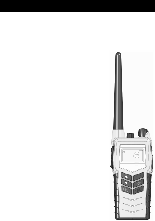
Chapter 1
1
Introduction
Your GMDSS VHF
Your portable VHF transceiver, is approved to
fulfil the GMDSS requirements for portable VHF
radios for Safety at Sea and is waterproof to the
IP67 standard.
As part of the required safety equipment, the R5 is
to be used in an emergency situation. However
the best way to guarantee functionality in an
emergency situation, is to use the radio in daily
communication on board.
The unique battery concept makes the radio
suited for both daily use and emergency
situations. The primary emergency battery is to
be stored for emergency situations and a
secondary rechargeable battery can be used for
daily communication in your new portable VHF
transceiver.
The radio is designed with a unique man
machine interface, an excellent grip even with
gloves, and large tactile buttons.
The display has red adjustable backlight which
makes the display visible even at night.
The radio is equipped with a lanyard and a belt
clip.
0641

Introduction
2
Performance
For best performance of the transceiver keep the following in mind:
• Keep clear of metal environment.
• Hold the transceiver vertically and 10 cm from lips and push the PTT
when transmitting.
• In receive mode carry the transceiver vertically with belt clips.
• To preserve battery power, adjust squelch to close the loudspeaker
when there is no signal.
• If you are in a lifeboat keep the antenna as high as possible.
Channels
This radio operates with the following channels:
Notes:
• All channels are Simplex.
• Tx power is limited to 1 W on channels 75 and 76.
0703
61115687377
81216697487
91317717588
10 14 67 72 76
Chapter 2
3
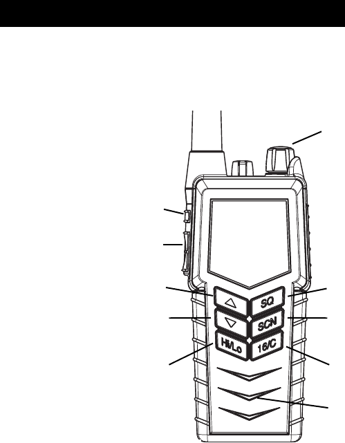
Operation
Controls
Keys and buttons
1. On/off/volume
2. Light/Lock
3. Push To Talk (PTT)
4. Up key
5. Down key
6. Hi/Lo output power
7. Squelch
8. Scan
9. Priority channel (16)/
Call channel
10. Loudspeaker/microphone
1
2
3
4
5
6
7
8
9
10
Operation
4
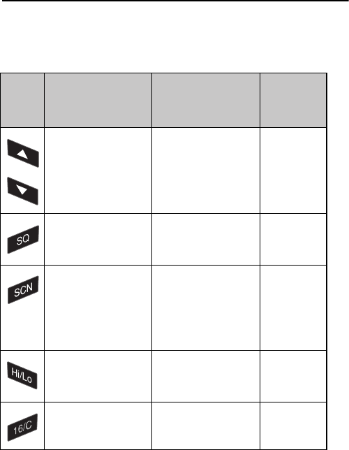
Key presses
Pressing and holding certain keys gives access to additional functions,
shown in the table below.
Key Short press
(1 beep)
Long press
(2 beeps)
Extra long
press
(3 beeps)
Show next available
item in the list (up or
down).
Default: Channel
selection
Run through available
items, or
select tagged channels
A () or B ().
Run through
available
items if an A
or B channel
is tagged
Activate Squelch
control (Adjust with
up/down arrows).
Monitor function. Open
Squelch completely.
1 press: Activate/
terminate Dual/Triple
watch.
2 presses: Activate
memory scan.
Add/Delete channel
from memory scan.
Toggle between high
and low transmitter
power.
Select channel 16. Select programmed
Call channel.
Program Call
channel.
0703
Operation
5
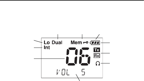
The display
The display holds various fields of information, explained below.
1. Current working channel.
2. Current channel mode.
3. “Lo”: Reduced transmitter power.
Full transmitter power is not shown in display.
4. Dual watch activated.
5. Current working channel is marked for scanning.
6. Keypad is locked.
7. Battery level indicator.
8. Transmitting (Tx) /Receiving (Rx).
9. Accessory is connected.
10. Service line for various purposes. In this example the volume level.
1
3
456
7
8
9
10
2
0643
Operation
6
Using the GMDSS VHF
Basic functions
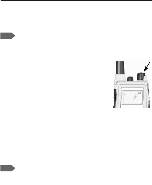
Switching the radio on and off
•To switch the radio on, turn the knob at the top
of the radio clockwise.
The display lights up showing the last used
channel and the battery level.
•To switch the radio off, Turn the knob back
counter-clockwise until it clicks.
Selecting the working channel
• To select channel 16 (Distress or Safety), press the 16/C key.
• To select the Call channel, use a long press on 16/C.
• To select among all available channels, press or on the keypad.
For fast selection, press and hold or .
The display shows the currently selected channel.
Note Before using the radio, mount the antenna at the top of the
radio. The antenna is delivered with the radio.
Note Long press on or can also be used to select preferred
channels. For information on how to program preferred
channels, see Configuring the GMDSS VHF on page 11 .
0643
Operation
7
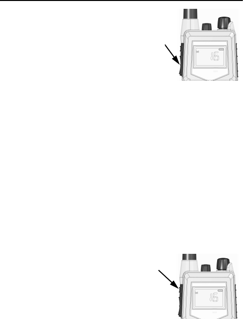
Activating a call
To activate a call to the selected channel, press and
hold the PTT button on the side of the radio.
The radio transmits as long as the PTT button is
pressed. A small Tx sign next to the channel num-
ber indicates when the radio is in transmit mode.
Adjusting the volume
•To increase the volume, turn the on/off knob at the top of the radio
clockwise.
•To decrease the volume, turn the knob counter-clockwise.
The display shows the level of the volume, e.g. “VOL 5”, while it is
adjusted.
Using Squelch control
•To activate Squelch control, press the SQ key.
•To set the Squelch level, press (closing) or (opening). The
display shows the Squelch level while it is adjusted, e.g. “SQ 5”.
Adjusting the display backlight
•To turn on the backlight, press the
Light/Lock button on the side of the radio.
•To adjust the backlight level, press or
within 3 seconds after turning on the light.
The display shows the level while it is
adjusted, e.g. “DIM MED”.
1211

Operation
8
Using Dual watch
To activate Dual watch, press the SCN key.
The display shows “Dual” at the top and “16” at the bottom right.
The radio toggles between the selected channel and channel 16.
•To terminate Dual watch, press SCN again.
Scanning channels
•To activate scanning memory, press 2 times SCN within 2 seconds.
During scanning, the display shows “SC” in the channel field. The
radio toggles between channel 16 and each of the channels marked
for scanning.
•To terminate scanning, press SCN once.
Changing the transmitter power
To change the transmitter power, press the Hi/Lo key. The display shows
“Lo” when power is set to low. Otherwise maximum power is used.
Locking the keypad
•To lock the keypad, press and hold the Light/Lock button. The display
shows a key symbol when the keypad is locked.
•To unlock the keypad, press and hold the Light/Lock button again.
0740

Operation
9
Other functions
Programming the Call channel
To program the Call channel, do as follows:
1. Press and hold 16/C until the current Call channel number is flashing.
2. Select the channel with or .
3. Press 16/C to confirm.
Programming the scanning memory
To add a channel to the scanning memory, select the channel and then
press and hold the SCN key until the display shows MEM at the top.
To remove a channel from the scanning memory, select the channel and
then press and hold the SCN key until the MEM sign disappears from the
display.
Alive beep
To enable “ALIVE” function do as follows:
1. Select the channel where ALIVE function is desired to be transmitted.
2. Press and hold the Hi/Lo until you see “ALIVE ON” on the radio
display. It takes approx. a second.
3. Now “ALIVE” is transmitted by a "beep" on the working channel, with
approx. 4-second intervals.
To deactivate “ALIVE” function do as follows:
• Press and hold the Hi/Lo pressed until “ALIVE ON” no longer appears
on the radio display. It takes approx. a second.
0740

Operation
10
“ALIVE” function is also deactivated when
• The channel is changed.
• The radio is turned OFF and ON again.
• Watch or scanning is enabled.
• Squelch is open.
Refer to ALIVE on page 13
1211

Operation
11
Configuring the GMDSS VHF
Entering and using configuration mode
•To enter configuration mode, press and hold the Light/Lock button
while turning on the radio.
The bottom line of the display shows the current menu item/setting.
•To exit configuration mode, turn off the radio or press any key except
, and the Light/Lock button.
Using the PTT button or leaving the radio inactive for 10 seconds also
causes the radio to exit configuration mode.
•To change a setting, press or .
•To confirm the current setting and go to the next menu item, press
the Light/Lock button.
Note The radio is not operational in configuration mode.
0643

Operation
12
Configuration settings
Configuration mode is used to program preferred channels and volume of
key beep and battery alarm.
The following settings are available in configuration mode.
BEEP MAX Status click/beep sound on key press, long
press (settings/programming saved) and
battery alarm. Maximum level.
MIN Status click/beep sound on key press, long
press (settings/programming saved) and
battery alarm. Minimum level.
OFF All beeps off.
PREFA OFF Remove tag “A” for current working channel.
ON Tag current working channel with “A”. If
another channel was previously tagged “A”,
this is overruled.
• The working channel can now be selected
with a long press on .
PREFB OFF Remove tag “B” for current working channel.
ON Tag current working channel with “B”. If
another channel was previously tagged “B”,
this is overruled.
• The working channel can now be selected
with a long press on .
VER X.XX.XX Software version. Read-only.
0703

Operation
13
ALIVE OFF Factory default state.
ON Press to set “ALIVE” on.
ADD NAME A-Z, 0-9 Makes it possible to name the channels.
The name must contain a maximum of 9
characters, use only capital letters, digits and
spaces.
Press Light/Lock to confirm programming.
Note: The name appears in the service line on
the display.
12111211

Operation
14 1211
Chapter 3
15
Batteries
Battery types
• The yellow primary battery pack contains a non-rechargeable Lithium
battery. This battery pack is only to be used in case of emergency.
• The black secondary battery pack contains a rechargeable battery.
This battery pack is for daily use.
The primary battery
Before using the primary battery, remove the seal on the battery pack.
Then do as follows:
1. Attach the battery pack to the radio as
shown.
2. Lock the battery with the safety lock at
the bottom.
The primary battery is capable of providing
sufficient power for 8 hours of operation
defined as 10% Tx, 10% Rx and 80%
standby.
When the primary pack is not in use it must
always be placed in the dedicated rear
position in the charger cradle, see The
battery charger on page 18.
Important The yellow primary battery pack is only for emergency use,
and is not rechargeable.
1
2
0709
Batteries
16
The secondary battery
Battery level indication
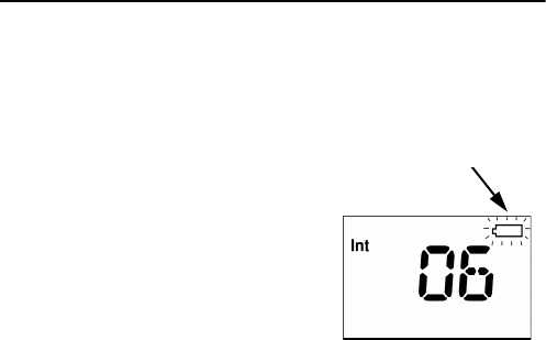
The black secondary battery pack is for daily use of the radio. When the
battery level is low, you should recharge the battery.
The radio display shows the battery
status. When the battery symbol is empty
and flashing, the battery should be
recharged as soon as possible.
0643
Batteries
17
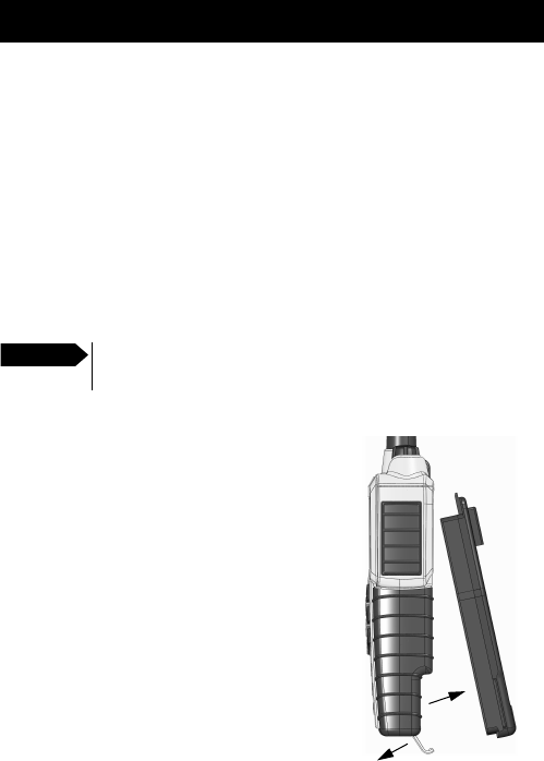
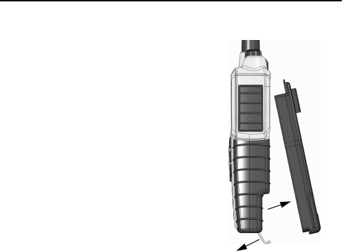
Removing and inserting the battery pack
To remove the battery pack, do as follows:
1. Open the safety lock as shown.
2. Remove the battery.
To insert the battery pack, attach the battery
and close the safety lock as shown on the
previous page.
1
2
0740
Batteries
18
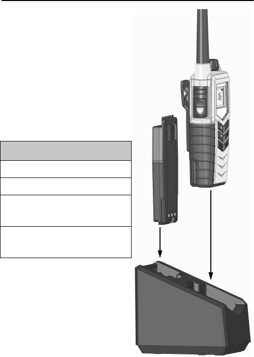
The battery charger
The chargers has two compartments.
Single Charger Kit
• A rear compartment only for
storing a spare battery. It does not
have a charger function.
• A front compartment for
recharging the battery alone or
while attached to the radio.
Dual Charger Kit
• It is possible to charge a battery in
rear compartment simultaneously
with the radio/battery in front.
Single Charger Accessory Option
Secondary battery (black, rechargeable)
Single Charger Base
AC/DC converter, length 150cm
(100-240V~/12V DC out)
12-24V DC Connection cable,
length 150cm
1211

Batteries
19
Installing the charger
Mounting the charger
There are several options for mounting one or more chargers on a table
or a wall.
For information on dimensions and screw positions, refer to Dimensional
drawing, chargers on page 31.
When mounting the charger, make sure it is placed in a dry place and
away from direct sunlight. The charger is not waterproof.
Connecting to power
The charger can be supplied with DC or AC.
DC: Connect the 12-24VDC Connection Cable between the DC supply and
the connector on the underside of the charger.
AC: Connect the AC/DC adapter to the connector on the underside of the
charger. Then connect the AC/DC adapter to the AC outlet.
Recharging the secondary battery
To recharge the secondary battery, place the radio with battery or the
battery alone in the front position of the charger cradle.
If the radio cannot turn on due to completely discharged battery, then
turn off the radio and place it in the charger or charge the battery alone.
The light indicators on the charger cradle show the status as follows:
• Green light: Power is connected to the charger.
• Slow red flash: Charging in progress.
Important Do not attempt to recharge the yellow primary battery!
0806

Batteries
20
• Quick red flash (twice per second): Charging error, e.g. battery
defect or temperature out of range.
• Steady red light: Charging completed. Trickle charge mode.
Charging time with emtpy battery: VHF off
approx. 4 hours, VHF on: approx. 5 hours.
The battery indicator on the radio display
indicates if the radio is placed in the
charger while radio and charger are both
powered.
0806
Chapter 4
21
Equipment and accessories
External equipment
The R5 VHF radio accessory connector can support remote handset or
headset connection. Contact the suppler of the accessory device for
detailed connection information.
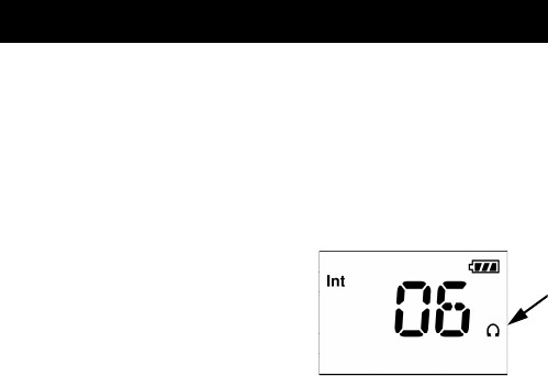
When external equipment is connected
to the radio, the right side of the display
will show a headset.
Impact on radio operation
The external equipment can have a
built-in PTT button, speaker and microphone. Thus a connection has per
default the following impact on the radio operation:
• If a speaker or earpiece is built into the detected external equipment,
the sound device of the external equipment is used, and the internal
radio speaker is disabled.
• The external accessory microphone is selected as audio input device,
when the external PTT button is pressed. The transceiver microphone
is used as audio input device when the transceiver PTT button is
pressed.
• This behaviour can be changed in the service tool.
0740

Equipment and accessories
22
Accessories
List of accessories
The following accessories are delivered with your radio:
Batteries, charger, AC/DC Converter and 12VDC Connection are described
inBatteries on page 15.
To mount the antenna, simply screw it into the threaded bush at the top
of the radio.
Use of lanyard is only for hand held operation. Put it around the wrist to
prevent dropping the radio.
Accessory
Primary battery non rechargeable, B3502
Belt clip
Antenna
Lanyard
User Manual (this manual)
0945
Equipment and accessories
23
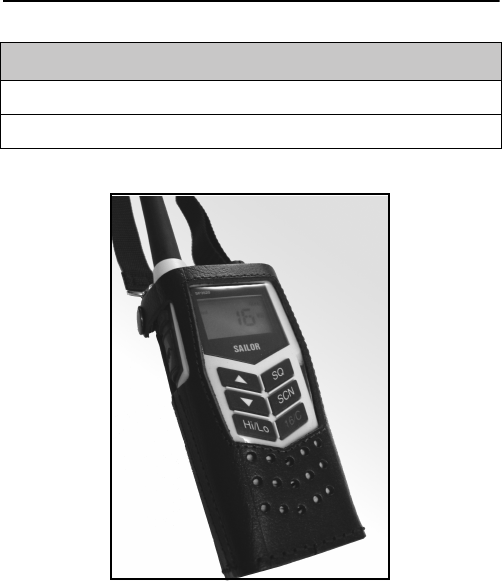
Accessories you may buy
Leather Case
Warning!
The display must always be kept away from the body to reduce the RF
explosure when body worn.
Accessory
Dual Position Charger Kit
Leather Case
0945
Equipment and accessories
24
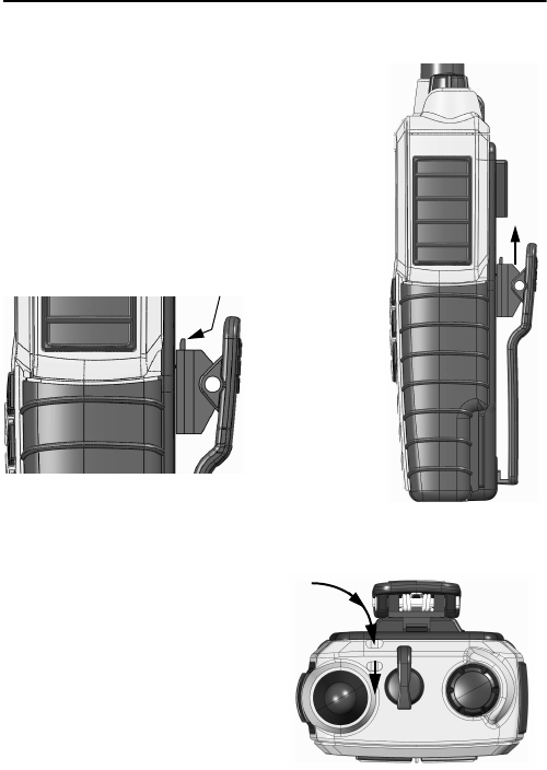
Attaching and removing the belt clip
To attach the belt clip, slide the belt clip upwards
into the rails at the back of the radio until it locks.
To remove the belt clip, press the projection at
the top of the belt clip to release the lock and
slide the belt clip downwards out of the rails.
Attaching the lanyard
Do as follows:
1. Take the lanyard through the
eye at the top of the radio.
2. Put one end of the lanyard
through the loop at the other
end of the lanyard and pull to
tighten.
Release lock
Top view
0740

Chapter 5
25
Troubleshooting
Displaying errors
Some errors result in an error message in the display. These error
messages are listed below.
Display text Problem Type Actions
Err
EMPTY BAT
The battery voltage is
below a critical level,
where further operation
would damage the battery.
Severe.
Radio is non-
functional.
Change/recharge
the battery.
Err
HW ERR
Hardware error. Severe.
Radio is non-
functional.
Service required.
ILLEGAL
Context fails operation.
This text will appear on
the following occasions:
• Multiple watch is
selected on channel 16,
or in channel regions
where it is not allowed.
• High power is selected
on a channel where it is
prohibited.
• Transmission on
blocked channels
Fail
operation
Consider operation
in a different
context.
0845

Troubleshooting
26 0845

Appendix A
27
Technical specifications
Technical data R5 GMDSS VHF
General
Item Specification
RX frequency range 155.000 - 163.425 MHz
TX frequency range 155.000 - 161.450 MHz
Modulation 16K0G3E
Power supply 7.2 VDC Li battery
Current drain at 2 W TX 1.4 A
Current drain at 1 W TX 0.8 A
Current drain RX max audio 0.25 A
Antenna port 50 ohm
Primary Battery Lithium Iron Disulfide, 3000 mAh
Secondary Battery (option) Lithium-Ion, 1800 mAh rechargeable
Operating temperature -20°C to +55° C
Water ingress protection IP67
Frequency stability Better than ±0.7 kHz
Weight with emergency battery 340g
0740

Technical specifications
28
Transmitter
Receiver
Item Specification
RF output power 2 W /1 W
RF output power, Canada 2.5 W ±1 dB / 0.75 W ±1 dB
Max deviation ±5 kHz
Spurious emission < 0.25 uW
Adjacent channel power > 70 dB
Item Specification
Sensitivity (20 dB SINAD) -117 dBm typical
Intermodulation Better than 70 dB
Spurious response > 70 dB
Adjacent channel selectivity > 70 dB
Audio output, internal 0.25 W at 10% dist.
Audio output, external 0.25 W/8 ohm
0740

Technical specifications
29
Battery life guidelines
Primary battery (non-rechargeable)
The primary non-rechargeable battery pack is capable of providing
sufficient power for the specified 8 hours according to regulations.
The battery is marked with an expiry date. Replace the battery at or
before this date.
To ensure a long lifetime keep the battery in the store position in the
charger and avoid high temperature and direct sunlight.
Secondary battery (rechargeable)
During daily use, always keep the battery fully charged and away from
hot areas.
Keep the battery terminals dry and clean.
Never discharge beyond the specifications of the battery.
Operation/Standby time depends on usage. Generally, the more the radio
is transmitting, the faster it will drain the battery. Also, the “Hi” power
setting will drain the battery faster than the “Lo” setting.
Approximate figures are:
• A battery can be stored for 4 to 6 month at 25°C if charged to 25%.
• The battery will normally last for 5 to 9 hours of use on a fully
charged battery.
Note New batteries should be placed in the charger for minimum 12
hours first time.
0709
Technical specifications
30
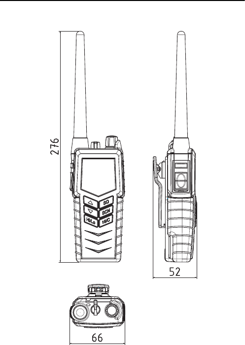
Dimensional drawing, transceiver
0709
Technical specifications
31
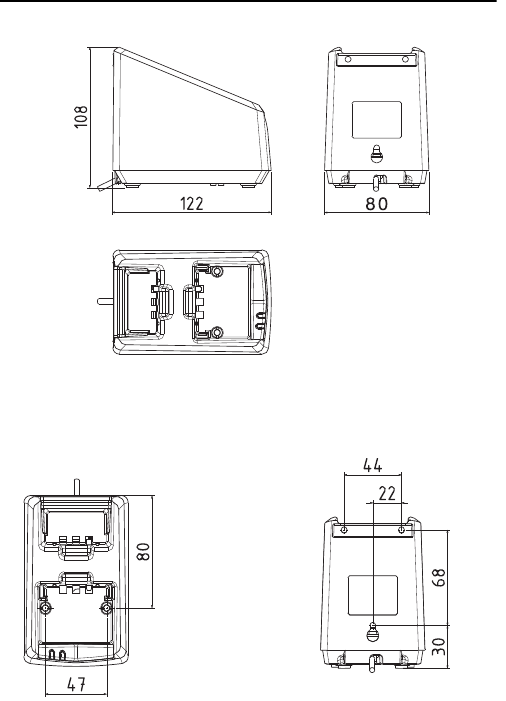
Dimensional drawing, chargers
Mounting Possibillities
Desktop mounting, top view Wall mounting, rear view
0740

Technical specifications
32 0703
Appendix B
33
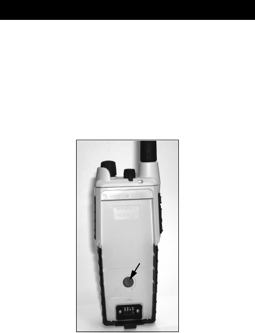
Attention
Goretex Membrane
To keep the VHF watertight, is it very important that the goretex
membrane behind the label under no circumstances must be damaged or
removed.
0740

Attention
34 0740
Orolia Ltd
Silver Point
Airport Service Road
Portsmouth PO3 5PB
United Kingdom
Phone: +44 (0)23 9262 3900
Fax: +44 (0)23 9262 3998
Email: service.mcmurdo@orolia.com
Website: www.mcmurdomarine.com
20-150 Issue 1
An Orolia Group Business
98-124294-MCM-G