Thrane and Thrane A S RT5020 VHF Marine Radiotelephone User Manual B5022GB 1 pmd
Thrane & Thrane A/S VHF Marine Radiotelephone B5022GB 1 pmd
UserManual.wiki
>
Thrane and Thrane A S
>
RT5020 User Manual
User manual
Navigation menu
Upload a User Manual
Namespaces
Wiki Guide
HTML
PDF
Info
Views
User Manual
Discussion / Help
Navigation

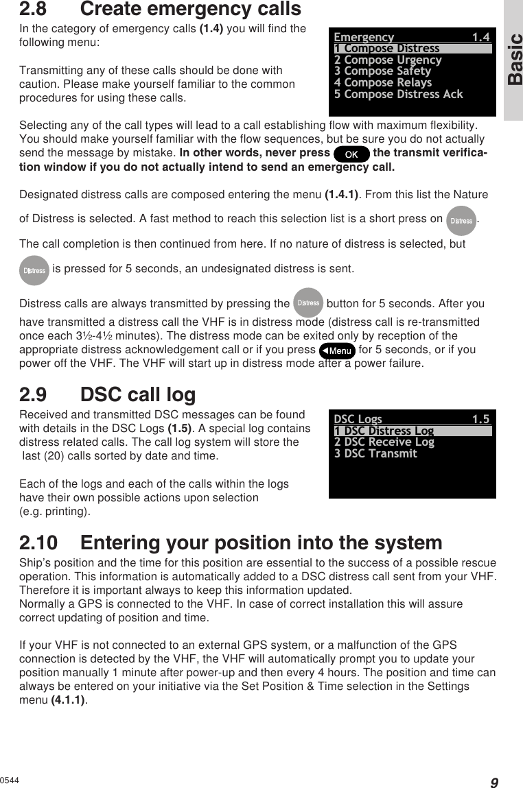
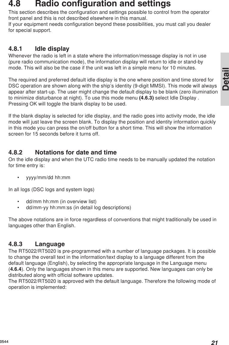
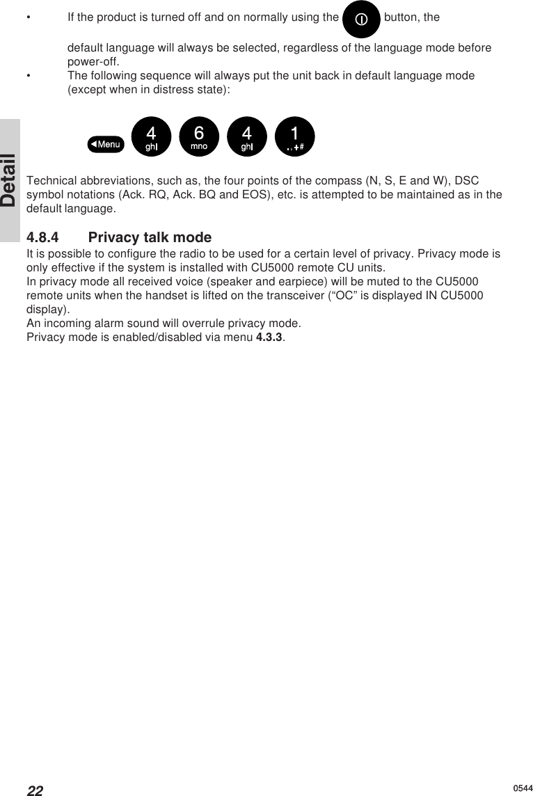
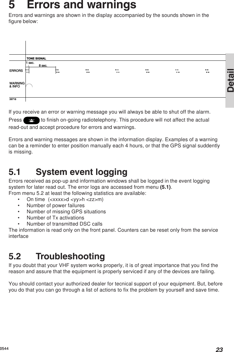
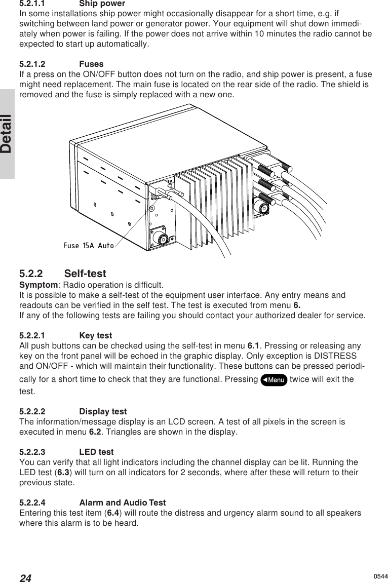
![3Basic1 Radio communication in brief1.1 Powering VHFThe VHF is turned on by a single press on the ON/OFF/Volume button. The VHFis turned off by pressing the ON/OFF/Volume button for 3 seconds.Always indicated by a count down window in the information display, except if theradio is powered down in distress mode.Any connected devices (Alarm Panel, Handset, CUs) will be operational only ifthe VHF is powered.1.2 Operating VHF radio communicationThe VHF is operated by means of a handset.To bring the VHF in transmission mode the handset must be hooked off and the PTT buttonon the handset has to be pressed. Transmission is indicated by the lighted TX indicator.Receive mode is always reached by releasing the PTT button.PTTPTTPress PTTRelease PTThooked offhooked onHandsetHandsetTransmit and receive is performed on the working channel shown in the telephone display.If the handset is used with an RT5020 duplex radio, received signal can always be monitoredin the handset earpiece. With the RT5022 simplex/semi-duplex radio the received voicesignal can only be monitored in the earpiece while PTT is released.1.3 Receiving a call on Channel 16When you hear your call name in the loudspeaker:1. Lift the handset.2. Press the PTT key.3. Repeat the name of the station calling you and say “This is [your ship’s name].”4. Suggest a channel other than 16 by saying “Channel [suggested number]”.5. Say “Over” and release the PTT keyto allow your caller to confirm the suggested new channel.0544](https://usermanual.wiki/Thrane-and-Thrane-A-S/RT5020/User-Guide-610364-Page-9.png)
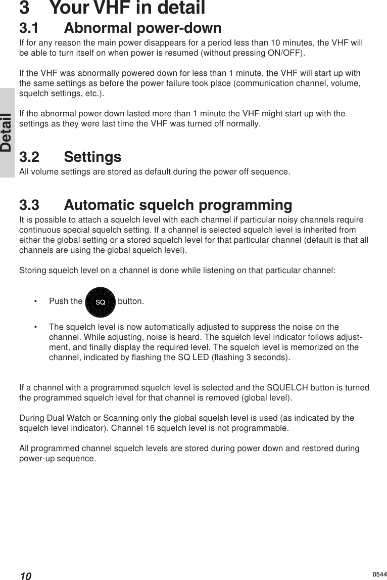
![4Basic05446. Switch to the new channel – for example, channel 71– and begin your conversation. Press PTT only when you are talking. If you are on asimplex channel (in other words, a channel that can carry only one transmission at atime), always say “Over” just before releasing. With duplex channels (ship-shorecalls), the conversation can be two-way as with a normal land telephone calls.1.4 Making a radiotelephone callA radiotelephone call is preferably to be commenced using DSC. Alternatively the followingpublic calling procedure shall be used:1. Select channel 16 (by pressing ) or other agreed channel.2. Lift the handset.3. Press the PTT key and make your call.First, say the name of the stationyou are calling three times.Then say “This is [your ship’s name”], again three times.Finally, say “Over”.4. Release the PTT key to listen.5. When answered, agree upon a channel,switch to that channel – for example, channel 6 – and begin your conversation. PressPTT only when you are talking. If on a simplex channel (in other words, a channelthat can carry only one transmission at a time), always say “Over” just beforereleasing.1.5 Speaker volumeThe volume in the loudspeaker (internal and optional external) is adjusted by turning theVOLUME control. The volume level is visualized in the telephone display. The volume can beadjusted to a mute mode by turning the volume control left (down). If the volume is adjustedto the mute level the VOL LED will flash.1.6 Earpiece volumeThe volume level of the default handset earpiece is adjusted by selecting the HandsetVolume menu (4.3.1).The and buttons are used to adjust the level. The level is indicated in theinformation/message display.1.7 SquelchThe squelch level is adjusted by using the squelch control. The actual squelchlevel is visualized in the telephone display.](https://usermanual.wiki/Thrane-and-Thrane-A-S/RT5020/User-Guide-610364-Page-10.png)