Thrane and Thrane A S
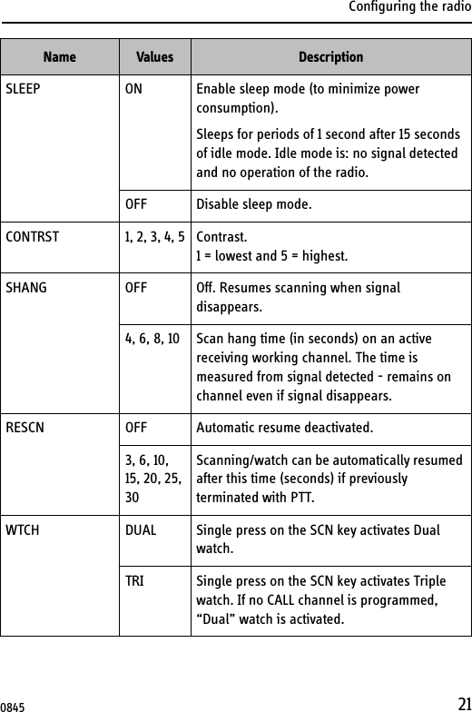
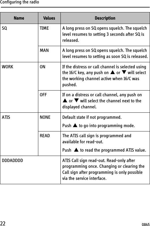
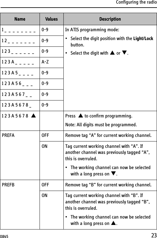
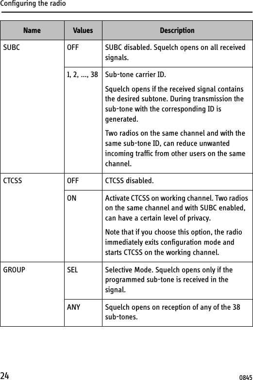
 SP3530 Sailor SP3530 Hand Held VHF Radiotelephone (ATEX) User Manual SP3530

Thrane & Thrane A/S Sailor SP3530 Hand Held VHF Radiotelephone (ATEX) SP3530

manual

DraftSAILOR SP3530 ATEX VHFUSER MANUAL
DraftEmergency procedure•   Turn the knob at the top of the radio clockwise. The display lights up     showing the last used channel and the battery level.•   Select channel 16 (Distress or Safety), press the 16/C key.•   Press the PTT and say:  —  “MAYDAY, MAYDAY, MAYDAY”,  —  “This is”..... ships name repeated three times —  — “MAYDAY”  —  “This is”..... ships name and call sign,  —  The ship’s position in latitude and longitude or other reference    to a known geographical location,  —  The nature of distress and assistance wanted,  —  Any other information which might facilitate the rescue. — “OVER”•   Release PTT and listen for answer.
DraftIMPORTANT INFORMATIONSafe use of ATEX equipment:• Do not change the battery in wet or humid environments.• Always keep battery connectors dry and clean.• Use only with Sailor ATEX approved accessories. Alternatively ATEX approved accessories in compliancewith the accessory connector ATEX specification may beused.• Do not change accessories in wet or humid enviroments.• Do not charge the battery in hazardous area.• For charge of battery use Part no: 403505A - ATEX CH3505 Compact Charger, Part no: 403507B - ATEX CH3507 Single Position Charger or Part no: 403508B - ATEX CH3508 Dual Position Charger• Use only battery type Sailor B3503 or B3504.• Do not use a mechanically damaged radio.• Unpacking of the radio and accessories and the removal ofthe protective film in front of the display window must nottake place in the ATEX protected area.99-127722-B0850
Draft
DraftiSP3530 ATEX VHFDocument number: TT 98-124306-BRelease date: January, 2009Copyright: © 2009 Thrane & Thrane A/S. All rights reserved.Trademark Acknowledgements•SAILOR is a registered trademark of Thrane & Thrane A/S.•Other product and company names mentioned in this manual may be trademarks or trade names of their respective owners.Warranty limitationIMPORTANT - The radio and batteries are sealed waterproof units. To create and maintain the waterproof integrity they were assembled in a controlled environment using special equipment. The radio and batteries are not user maintainable units, and under no circumstances should the units be opened except by authorized personnel. Unauthorized opening of the units will invalidate the warranty.DisclaimerAny responsibility or liability for loss or damage in connection with the use of this product and the accompanying documentation is disclaimed by Thrane & Thrane. The information in this manual is provided for information purposes only, is subject to change without notice and may contain errors or inaccuracies.Manuals issued by Thrane & Thrane are periodically revised and updated. Anyone relying on this information should acquire the most current version e.g. from the Thrane & Thrane Extranet at: http://extranet.thrane.com. Thrane & Thrane is not responsible for the content or accuracy of any translations or reproductions, in whole or in part, of this manual from any other source.0905
DraftiiPrecautionsAvoid water and salt in the I/O connector and keep it clean frequently.Only use original Thrane & Thrane battery packs. Make sure they are clean and dry before attaching the transceiver. Be careful not to damage any gaskets.Only use the original Thrane & Thrane charger for the rechargeable battery.Be very careful when handling the Lithium batteries. With correct use they are safe but any misuse might cause dangerous situations.Never short circuit the battery terminals, never expose the transceiver and the batteries to extreme temperature or fire and never use any kind of violence.Avoid close contact between the antenna and parts of the human body. The top of the antenna must never be closer than 5 cm to the body when transmitting.Do not submerge the transceiver more than 1 m for 30 minutes.Keep the transceiver at least 0.3 m away from the magnetic compass.0845
DraftiiiTraining informationSAILOR SP3530 ATEX VHF is designed for "occupational use only". It must be operated by licensed personnel only.The SP3530 complies with the FCC RF exposure limits for "Occupational Use Only". • FCC OET Bulletin 65 Supplement C, evaluating compliance with FCC guidelines for human exposure to radio frequency electromagnetic fields.• American National Standards Institute (C95.1) IEEE standard for safety levels with respect to human exposure to radio frequency electromagnetic fields, 3 kHz to 300 GHz.• American National Standards Institute (C95.3) IEEE recommended practice for the measurement of potentially hazardous electromagnetic fields - RF and microwaves.Correct useFor best performance, hold the radio vertically and 10 cm away from the head when talking into the microphone.Warning! Your Thrane & Thrane VHF radio generates electromagnetic RF (radio frequency) energy when transmitting. To ensure that you are not exposed to excessive amounts of energy and thus to avoid health hazards from excessive exposure to RF energy, all persons must be at least 5 cm away from the antenna when the radio is transmitting.0845
iv
1Chapter IntroductionYour ATEX VHF .....................................................................1Performance ....................................................................... 2Channels ............................................................................. 2Chapter OperationControls ............................................................................... 5Keys and buttons ................................................................5The display .........................................................................7Using the VHF  ..................................................................... 8Basic functions ...................................................................8Other functions .................................................................. 11Chapter BatteriesBattery level indication ......................................................15Removing and inserting the battery pack ...........................15The battery charger  ...........................................................16Installing the charger  ........................................................16Recharging the battery ......................................................17Chapter  Configuring the radioConfiguration mode  ...........................................................19Entering and using configuration mode  ............................19List of configuration settings .............................................200845
2Chapter Equipment and accessoriesExternal equipment ............................................................27List of equipment .............................................................. 27Connecting external equipment ........................................ 27Impact on radio operation ................................................28Accessorie connector ........................................................28Accessories ....................................................................... 29List of accessories .............................................................29Attaching and removing the belt clip .................................31Attaching the lanyard ........................................................31Chapter TroubleshootingDisplaying errors .............................................................. 33App. Technical specificationsTechnical data SP3530  .......................................................35General ............................................................................ 35Transmitter ....................................................................... 36Receiver ........................................................................... 36Battery life guidelines ........................................................38Dimensional drawing, transceiver  .....................................39Dimensional drawing, chargers ........................................ 40Declaration of Conformity  ................................................. 42TÜV Certificate................................................................... 43App. AttentionGoretex Membran  ..............................................................470905
Chapter 11IntroductionYour ATEX VHFThe SP3530 ATEX VHF is designed for flexibility in daily use. It connects easily to external equipment like headsets and fist mikes, making the SP3530 suitable for any noisy environment.Main features:Unique man machine interface, an excellent grip even with gloves, and large tactile buttons. Display with red adjustable backlight which makes the display visible even at night. Built-in “sleep” function, minimizing power consumption and improving battery lifetime.Selectable 12.5 kHz narrow band or 25 kHz wide band operation. Scrambling function for privacy calls.CTCSS function for selective opening of Squelch.A lanyard and belt clip included.A huge accessory program comes with the SAILOR SP3500 series. Please find the nearest SAILOR distributor on www.thrane.com.0845
Introduction2PerformanceFor best performance of the transceiver keep the following in mind:• Keep clear of metal environment.• Hold the transceiver vertically and 10 cm from lips and push the PTT when transmitting.• In receive mode carry the transceiver vertically with belt clips.• To preserve battery power, adjust squelch to close the loudspeaker when there is no signal.• If you are in a lifeboat keep the antenna as high as possible.ChannelsThis radio operates default with the following channel designators (see also ITU-R M.1084-4), depending on the configuration (see the notes on the next pages):19172560687785 US W-ch. CA W-ch.2 10182661697886 W1 W8 W1311192762717987 W2W9 W2412202863728088 W3W10 W351321 647381 W461422 657482 W571523 667583 W681624 677684 W70845
Introduction3Channel modesThe notes in the following sections list the channel restrictions that apply for each channel mode.For information on how to select a channel mode, see Entering and using configuration mode on page 19 and CHAN on page 20. National frequency regulations shall always be respected and might restrict operation for this type of equipment.International channelsNote:Tx power is limited to 1 W on channels 75 and 76.US channelsNotes:• Tx power is limited to 1 W on channels 13, 67 and 77.• The channels 2, 4, 60, 61, 62, 75 and 76 cannot be selected.• The Weather channels (US W-ch. in the channel table) can only be used in Rx direction.• Channel 15 can only be used in Rx direction. Tx direction is blocked.• The channels 1, 3, 5, 7, 18, 19, 21, 22, 23, 63, 64, 65, 66, 78, 79, 80, 81, 82 and 83 may only be used as simplex channels (and is marked A). Channel 20 may be used as semi-duplex and simplex as 20A. 0845
Introduction4Canadian channelsNotes:• Tx power is limited to 1 W on channels 15, 17, 20, 65, 66 and 77.• The channels 19, 22, 63, 75, 76 and 81 cannot be selected.• The Weather channels (CA W-ch. in the channel table) can only be used in Rx direction.• The channel 21 can only be used in Rx direction, marked 21B. Tx direction is blocked.• The channels 4, 5, 7, 18, 19, 21, 22, 61, 62, 64, 65, 66, 78, 79, 80, 81 and 82 may only be used as simplex channels (and marked A). Channel 83 may be used as semi-duplex and simplex as 83A.Inland Waters (BI) channelsNotes:• Tx power is limited to 1 W on channels 15 and 17.• ATIS function is enabled on all channels.• Dual watch and Scanning modes are disabled.ATIS is automatically transmitted after each transmission in Inland Waters. See ATIS on page 22 for information on how to program the call sign.0845
Chapter 25OperationControlsKeys and buttons1. On/off/volume2. Light/Lock3. Push To Talk (PTT)4. Up key5. Down key6. Hi/Lo output power7. Squ elch8. Scan9. Priority channel (16)/ Call channel10. Loudspeaker/microphone123456789100845
Operation6Key pressesPressing and holding certain keys gives access to additional functions, shown in the table below. Key Short press (1 beep)Long press(2 beeps)Extra long press (3 beeps)Show next available item in the list (up or down).Default: Channel selectionRun through available items, or select tagged channels A (T) or B (S).Run through available items if an A or B channel is taggedActivate Squelch control (Adjust with up/down arrows).Monitor function. Open Squelch completely. Set period of time in configuration mode.1 press: Activate/terminate Dual/Triple watch.2 presses: Activate memory scan. Add/Delete channel from memory scan.Toggle between high and low transmitter power.Select channel 16. Select programmed Call channel.Program Call channel.0845
Operation7The displayThe display holds various fields of information, explained below.1. Current working channel.2. Current channel mode.3. “Lo”: Reduced transmitter power. Full transmitter power is not shown in display.4. Dual/Triple watch activated.5. Current working channel is marked for scanning.6. Keypad is locked.7. Battery level indicator.8. Transmitting (Tx) /Receiving (Rx).9. Accessory is connected.10. Service line for various purposes. In this example the volume level.11. Semi-duplex channel.13456789102110845
Operation8Using the VHFBasic functionsSwitching the radio on and off•To switch the radio on, turn the knob at the top of the radio clockwise. The display lights up showing the last used channel and the battery level.•To switch the radio off, Turn the knob back counter-clockwise until it clicks.Selecting the working channel• To select channel 16 (Distress or Safety), press the 16/C key.• To select the Call channel, use a long press on 16/C.• To select among all available channels, press S or T on the keypad. For fast selection, press and hold S or T. The display shows the currently selected channel. The bottom left corner of the display shows “Dup” if the channel is a semi-duplex channel.Note Before using the radio, mount the antenna at the top of the radio. The antenna is delivered with the radio. Note Long press on S or T can also be used to select preferred channels. For information on how to program preferred channels, see Configuring the radio on page 19.0845
Operation9Activating a callTo activate a call to the selected channel, press and hold the PTT button on the side of the radio.The radio transmits as long as the PTT button is pressed. A small Tx sign next to the channel num-ber indicates when the radio is in transmit mode.Adjusting the volume•To increase the volume, turn the on/off knob at the top of the radio clockwise.•To decrease the volume, turn the knob counter-clockwise.The display shows the level of the volume, e.g. “VOL 5”, while it is adjusted. Using Squelch control•To activate Squelch control, press the SQ key.•To set the Squelch level, press S (closing) or T (opening). The display shows the Squelch level while it is adjusted, e.g. “SQ 5”.Adjusting the display backlight•To turn on the backlight, press the Light/Lock button on the side of the radio.•To adjust the backlight level, press S or T within 3 seconds after turning on the light.The display shows the level while it is adjusted, e.g. “DIM MED”.0845
Operation10Using Dual/Triple watch•To activate Dual/Triple watch, press the SCN key.The display shows “Dual” or “Tri” at the top and “16” at the bottom right. The radio toggles between the selected channel and channel 16 in Dual watch. In Triple watch, the radio shifts between channel 16, the call channel and the selected channel.To select whether the SCN key should activate Dual or Triple watch, refer to Configuring the radio on page 19.•To terminate Dual watch, press SCN again.Scanning channels•To activate scanning memory, press 2 times SCN within 2 seconds. During scanning, the display shows “SC” in the channel field. The radio toggles between channel 16 and each of the channels marked for scanning.•To terminate scanning, press SCN once.Changing the transmitter powerTo change the transmitter power, press the Hi/Lo key. The display shows “Lo” when power is set to low. Otherwise maximum power is used.Locking the keypad•To lock the keypad, press and hold the Light/Lock button. The display shows a key symbol when the keypad is locked.•To unlock the keypad, press and hold the Light/Lock button again.0845
Operation11Other functionsProgramming the Call channelTo program the Call channel, do as follows:1. Press and hold 16/C until the current Call channel number is flashing.2. Select the channel with S or T.3. Press 16/C to confirm within 3 seconds.Programming the scanning memoryTo add a channel to the scanning memory, select the channel and then press and hold the SCN key until the display shows MEM at the top.To remove a channel from the scanning memory, select the channel and then press and hold the SCN key until the MEM sign disappears from the display.Low power operationThe radio can be operated in low power mode. In this mode battery life time is dramatically increased. Up to the first second of a received call might be lost if this mode is selected. Refer to SLEEP on page 21.Continuous Tone Coded Squelch SystemSelective squelch opening by sub-tone detection (CTCSS) can be enabled, using the configuration mode (see CTCSS on page 24). Please note that if the radio is operating with CTCSS on a channel, and a carrier is received, it may not be recognized in the loud speaker if the matching sub-tone is not detected. For this reason, be very careful not to use CTCSS programmed channels in emergency situations. For the same reason 0845
Operation12transmitting is prohibited (reporting "BUSY") if a (silent) carrier containing any sub-tone is active on the channel while pressing PTT.Channels programmed with CTCSS will have a clear identification in the service field, e.g. "CTCSS 22", while selected. Not all channels are allowed for CTCSS use. In maritime channel modes CTCSS is automatically disabled when • Product is turned off • A new channel is selectedFor private channels and ALT channel mode, the feature will remain until manually removed.ScramblerOn channels where it is allowed, you can set up voice scrambling, using configuration mode (see SCRM on page 25). Please note that if the radio is operating with scrambling on a channel, it is impossible to communicate with other radios that are not programmed with the same scrambler code. For this reason, be very careful not to use scrambled channels in emergency situations. Scrambled channels will have a clear identification in the service field, e.g. "SCRM 3", while selected. Not all regions allow the use of voice scrambling.In maritime channel modes scrambling is automatically disabled when• Product is turned off • A new channel is selectedFor private channels and ALT channel mode, scrambling will remain until manually removed.0845
Operation13Narrow band operationThe radio is prepared for narrow band operation. If narrow band operation is selected (see BAND on page 25), the number of channels are doubled in the maritime channels, according to international recommendations. Refer to the channel table in Channels on page 2. Channels are clearly identified with a preceding 4- or 2-digit, while operating in narrow band mode. Narrow band radios will not always be completely compatible with wide band operating radios.For single narrow band configured private channels or "ALT" channels, an “n” is displayed next to the channel designator.Note Prior to any initiation of scrambling, the operator must always identify the calling station in clear voice (unscrambled) on that channel. Use of scrambling may also be restricted by national laws.0845
Operation14 0845
Chapter 315BatteriesBattery level indicationWhen the battery level is low, you should recharge the battery.The radio display shows the battery status. When the battery symbol is empty and flashing, the battery should be recharged as soon as possible. Removing and inserting the battery packTo remove the battery pack, do as follows:1. Open the safety lock as shown.2. Remove the battery.To insert the battery pack, attach the battery and then close the safety lock.If the radio is not used for several weeks it is recommended to store the radio and battery separated to reduce self discharge of the battery.120845
Batteries16The battery chargerThe chargers has two compartments.CH3505• A compartment for recharging the battery alone or while attached to the radio.CH3507 •A rear compartment only for storing a spare battery. It does not have a charger function. • A front compartment for recharging the battery alone or while attached to the radio.CH3508• It is possible to charge a battery in rear compartment simultaneously with the radio/battery in front.Installing the chargerMounting the chargerThere are several options for mounting one or more chargers on a table or a wall. For information on dimensions and screw positions, refer to Dimensional drawing, charger on page 40.0845
Batteries17When mounting the charger, make sure it is placed in a dry place and away from direct sunlight. The charger is not waterproof.Connecting to powerThe charger can be supplied from DC or from AC using an AC/DC converter.DC: Connect the 12-24VDC Connection Cable between the DC supply and the connector on the underside of the charger. AC: Connect the AC/DC converter to the connector on the underside of the charger. Then connect the AC/DC converter to the AC outlet.Recharging the batteryTo recharge the battery, place the radio with battery or the battery alone in the front position of the charger cradle.If the radio cannot turn on due to complete discharged battery, then turn of the radio and place it in the charger or charge the battery alone.The light indicators on the charger cradle show the status as follows:• Green light: Power is connected to the charger.• Slow red flash: Charging in progress.• Quick red flash (twice per second): Charging error, e.g. battery defect or temperature out of range.• Steady red light: Charging completed. Trickle charge mode.0845
Batteries18Charging time with emtpy battery: VHF off approx. 4 hours, VHF on: approx. 5 hours.The battery indicator on the radio display indicates if the radio is placed in the charger while radio and charger are both powered.0845
Chapter 419Configuring the radioConfiguration modeEntering and using configuration mode•To enter configuration mode, press and hold the Light/Lock button while turning on the radio.The bottom line of the display shows the current menu item/setting.•To exit configuration mode, turn off the radio or press any key except S, T and the Light/Lock button.Using the PTT button or leaving the radio inactive for 10 seconds also causes the radio to exit configuration mode.•To change a setting, press S or T.•To confirm the current setting and go to the next menu item, press the Light/Lock button.Note The radio is not operational in configuration mode.0845
Configuring the radio20List of configuration settingsThe following settings are available in configuration mode.Name Values DescriptionLIGHT MAN Only Light/Lock button activates the backlight.KEY All keys and buttons, except PTT and volume control, activate the backlight.CHAN INT International channels.US US channels.CA Canadian channelsBI Inland waterways. ATIS and ATIS killer is enabled. All multiple watch is disabled.ALT Custom defined.BEEP MAX Status click/beep sound on key press, long press (settings/programming saved) and battery alarm. Maximum level.MIN Status click/beep sound on key press, long press (settings/programming saved) and battery alarm. Minimum level.OFF All beeps off.VER X.XX.XX Software version. Read-only.BAT X.XX Battery voltage (V). Read-only.TEMP XX.X Temperature (°C). Read-only.0845
Configuring the radio21SLEEP ON Enable sleep mode (to minimize power consumption).Sleeps for periods of 1 second after 15 seconds of idle mode. Idle mode is: no signal detected and no operation of the radio.OFF Disable sleep mode.CONTRST 1, 2, 3, 4, 5 Contrast. 1 = lowest and 5 = highest.SHANG OFF Off. Resumes scanning when signal disappears.4, 6, 8, 10 Scan hang time (in seconds) on an active receiving working channel. The time is measured from signal detected - remains on channel even if signal disappears.RESCN OFF Automatic resume deactivated.3, 6, 10, 15, 20, 25, 30Scanning/watch can be automatically resumed after this time (seconds) if previously terminated with PTT.WTCH DUAL Single press on the SCN key activates Dual watch.TRI Single press on the SCN key activates Triple watch. If no CALL channel is programmed, “Dual” watch is activated.Name Values Description0845
Configuring the radio22SQ TIME A long press on SQ opens squelch. The squelch level resumes to setting 3 seconds after SQ is released.MAN A long press on SQ opens squelch. The squelch level resumes to setting as soon SQ is released.WORK ON If the distress or call channel is selected using the 16/C key, any push on S or T will select the working channel active when 16/C was pushed.OFF If on a distress or call channel, any push on  S or T will select the channel next to the displayed channel.ATIS NONE Default state if not programmed.Push S to go into programming mode.READ The ATIS call sign is programmed and available for read-out.Push  S to read the programmed ATIS value.DDDADDDD ATIS Call sign read-out. Read-only after programming once. Changing or clearing the Call sign after programming is only possible via the service interface.Name Values Description0845
Configuring the radio231 _  _  _  _  _  _  _  _ 0-9 In ATIS programming mode:• Select the digit position with the Light/Lock button.• Select the digit with S or T.1 2 _  _  _  _  _  _  _ 0-91 2 3 _  _  _  _  _  _ 0-91 2 3 A _  _  _  _  _ A-Z1 2 3 A 5 _  _  _  _ 0-91 2 3 A 5 6 _  _  _ 0-91 2 3 A 5 6 7 _  _ 0-91 2 3 A 5 6 7 8 _ 0-91 2 3 A 5 6 7 8  S Press  S to confirm programming.Note: All digits must be programmed. PREFA OFF Remove tag “A” for current working channel.ON Tag current working channel with “A”. If another channel was previously tagged “A”, this is overruled.• The working channel can now be selected with a long press on T.PREFB OFF Remove tag “B” for current working channel.ON Tag current working channel with “B”. If another channel was previously tagged “B”, this is overruled.• The working channel can now be selected with a long press on S.Name Values Description0845
Configuring the radio24SUBC OFF SUBC disabled. Squelch opens on all received signals.1, 2, ..., 38 Sub-tone carrier ID. Squelch opens if the received signal contains the desired subtone. During transmission the sub-tone with the corresponding ID is generated.Two radios on the same channel and with the same sub-tone ID, can reduce unwanted incoming traffic from other users on the same channel.CTCSS OFF CTCSS disabled.ON Activate CTCSS on working channel. Two radios on the same channel and with SUBC enabled, can have a certain level of privacy.Note that if you choose this option, the radio immediately exits configuration mode and starts CTCSS on the working channel.GROUP SEL Selective Mode. Squelch opens only if the programmed sub-tone is received in the signal.ANY Squelch opens on reception of any of the 38 sub-tones.Name Values Description0845
Configuring the radio25SCODE OFF No scrambler code is assigned to the channel (selecting “ON” in the SCRM setting will have no effect).1, 2, 3, 4, 5, CCA selection between 5 fixed sets of scrambler characteristics, and a custom code (CC), can be assigned to the channel.Note that the custom code can be defined in the service interface.SCRM OFF Scrambler disabled.ON Activate scrambling on working channel. Two radios on the same channel and with scrambling enabled, can have a certain level of privacy.Note that if you choose this option, the radio immediately exits configuration mode and starts scrambling on the working channel.BAND 25.0 Wide band operation selected.12.5 Narrow band operation selected.• Intercepted channels will be denoted 2XX.• Standard maritime channels will be denoted 4XX.Name Values Description0845
Configuring the radio26
Chapter 527Equipment and accessoriesExternal equipmentList of equipmentThe following equipment can be connected to the radio:• SAVOX 400E Push-To Talk unit• SAVOX C500 Fist Mike• SAVOX NC/400 Noise-com• SAVOX HC-E Helmet-com• SAVOX K53004 Helmet unit• Peltor MT7H79 HeadsetWe recommend to remove all accessories during emergency use.All accessories listed might be used when body worn.Connecting external equipmentConnect the dedicated interface cable between the external equipment and the top connector on the radio.Interface cable Order numberFor SAVOX 400E 403500-940For SAVOX C500 403500-950For Peltor FL5261     403500-9520845
Equipment and accessories28When external equipment is connected to the radio, the right side of the display will show a headset.Impact on radio operationThe external equipment can have a built-in PTT, speaker and microphone. Thus connecting it to the radio will have the following impact on the radio operation:• If a microphone is built into the detected external equipment, the external equipment microphone is used, and the internal radio microphone is disabled.• If a speaker or earpiece is built into the detected external equipment, the external equipment sound device is used, and the internal radio speaker is disabled.• If a PTT or VOX is built into the detected external equipment, the external equipment PTT control is used, and the radio PTT button is disabled.Accessorie connectorPin 1. Loudspeaker,minimum 8 ohm impedance.Pin 2. Accessory power,3.5V maximum 3mA.Pin 3. Microphone input,Ri = 2.2kohm, 3V phantom power.Pin 4. GND0905
Equipment and accessories29AccessoriesList of accessoriesThe following accessories are delivered with your radio:Batteries, charger, AC/DC Converter and 12VDC Connection are described in Batteries on page 15. To mount the antenna, simply screw it into the threaded bush at the top of the radio.Use of lanyard is only for hand held operation. Put it around the wrist to prevent dropping the radio.Accessory Part numberATEX Secondary battery (blue, rechargeable), B3504 403504AATEX Compact Charger, CH3505 403505AAC/DC converter, length 150cm  (100-240V~ /12VDC out) 88-12553812-24VDC Connection cable, length 150cm 37-124381Belt clip 62-124320Antenna 88-124370Lanyard 41-124375SP3530 User Manual (this manual) TT 98-1243060845
Equipment and accessories30Accessories you may buyLeather CaseWarning!The display must always be kept away from the body to reduce the RF explosure when body worn.Accessory Part numberATEX Charger, CH3507      403507BATEX Dual Position Charger CH3508 403508BATEX Leather Case with shoulder strop 403500-2070845
Equipment and accessories31Attaching and removing the belt clipTo attach the belt clip, slide the belt clip upwards into the rails at the back of the radio until it locks.To remove the belt clip, press the projection at the top of the belt clip to release the lock and slide the belt clip downwards out of the rails. Attaching the lanyardDo as follows:1. Take the lanyard through the eye at the top of the radio.2. Put one end of the lanyard through the loop at the other end of the lanyard and pull to tighten.Release lockTop view0845
Equipment and accessories32 0845
Chapter 633TroubleshootingDisplaying errorsSome errors result in an error message in the display. These error messages are listed below.Display text Problem Type ActionsErrEMPTY BATThe battery voltage is below a critical level, where further operation would damage the battery.Severe. Radio is non-functional.Change/recharge the battery.ErrHW ERRHardware error. Severe. Radio is non-functional.Service required.ILLEGALContext fails operation. This text will appear on the following occasions:•Multiple watch is selected on channel 16, or in channel regions where it is not allowed. • High power is selected on a channel where it is prohibited.• Transmission on blocked channelsFail operationConsider operation in a different context.0845
Troubleshooting34 0845
Appendix A35Technical specifications Technical data SP3530GeneralItem SpecificationRx frequency range, landmobile 148.000 - 174.000 MHzTx frequency range, landmobile 148.000 - 174.000 MHzRx frequency range, maritime 155.000 - 163.425 MHzTx frequency range, maritime 155.000 - 161.450 MHzModulation    25 kHz    12.5 kHz16K0G3E8K50G3EPower supply 7.2 VDC Li batteryCurrent drain at 2 W Tx 1 ACurrent drain at 0.4 W Tx 0.7 ACurrent drain Rx max audio 0.25 AAntenna port 50 ohmBattery Lithium-Ion, 1800 mAh rechargeableOperating temperature -20°C to +55° C0845
Technical specifications36TransmitterReceiverWater ingress protection IP67Frequency stability Better than ±0.7 kHzWeight with emergency battery 370gItem SpecificationRF output power 2 W /1 WRF output power, Canada 1.7 W ±0.7 dB / 0.8 W ±1 dBMax deviation    25 kHz    12.5 kHz±5 kHz±2.5 kHzSpurious emission < 0.25 uWAdjacent channel power    25 kHz    12.5 kHz> 70 dB> 60 dBItem SpecificationSensitivity (20 dB SINAD) -117 dBm typicalItem Specification0740
Technical specifications37Intermodulation    25 kHz    12.5 kHz> 68 dB> 65 dBSpurious response > 70 dBAdjacent channel selectivity    25 kHz    12.5 kHz> 70 dB> 60 dBAudio output, internal 0.25 W at 10% dist.Audio output, external 0.25 W/8 ohmItem Specification0740
Technical specifications38Battery life guidelinesDuring daily use, always keep the battery fully charged and away from hot areas.Keep the battery terminals dry and clean.Never discharge beyond the specifications of the battery.Operation/Standby time depends on usage. Generally, the more the radio is transmitting, the faster it will drain the battery. Also, the “Hi” power setting will drain the battery faster than the “Lo” setting.Approximate figures are:• A battery can be stored for 4 to 6 month at 25°C if charged to 25%.• The battery will normally last for 5 to 9 hours of use on a fully charged battery. Note New batteries should be placed in the charger CH3507B or CH3508B for minimum 12 hours first time.0845
Technical specifications39Dimensional drawing, transceiver28055660845
Technical specifications40Dimensional drawing, chargersCH35053740442246.830.5Mounting PossibillitiesDesktop mounting, top view                 Wall mounting, rear view 70.487800845
Technical specifications410845Mounting PossibillitiesDesktop mounting, top view                                           Wall mounting, rear view CH3507 and CH3508
Technical specifications42 0845
Technical specifications43R&TTEDoc. no TT99-128497-BThrane & Thrane A/SDeclaration of Conformity with R&TTE DirectiveThe undersigned of this letter declares that the following equipment complies with thespecifications of EC directive 1999/5/EC concerning Radio & Telecommunications TerminalEquipment.Equipment included in this declarationSAILOR SP3530 ATEX Portable maritime VHF radiotele- PN = 623530Aphone (non GMDSS) orATEX Portable VHF radiotelephonefor landmobile useSAILOR B3503 ATEX Primary Battery PN = 403503ASAILOR B3504 ATEX Rechargeable Li-Ion Battery PN = 403504ASAILOR CH3505 Battery Compact Charger for ATEX PN = 403505ASAILOR CH3507 Battery Charger for ATEX PN = 403507BSAILOR CH3508 Dual Battery Charger for ATEX PN = 403508BAC/DC Adapter PN = 88-125538Equipment ApplicabilitySAILOR SP3530 is a simplex/semi-duplex handheld VHF radiotelephones designed formaritime and landmobile communication within the frequency range 148 MHz to 174 MHz.DeclarationSAILOR SP3530 conforms to the RTTE directive with respect toArticle 3(1)(a) the protection of health and safetyArticle 3(1)(b) electromagnetic compatibility requirementsArticle 3(2) effective use of the spectrum and avoidance of harmful interferenceWhich is shown by conforming to EU harmonized standard EN 301 178-2, EN 60945-Ed.4.0, EN 60950-1, EN 300 698-3 and EN 300 086-2.ManufacturerThrane & Thrane A/S Lundtoftegårdsvej 93D, DK-2800 Kgs. Lyngby, DenmarkPorsvej 2, DK-9200 Aalborg SV, DenmarkPlace and DateAalborg, 23. January 2009Chief Financial OfficerSvend Åge Lundgaard JensenPage 1 of 1Thrane & Thrane A/S ·  Lundtoftegårdsvej 93D  ·  DK-2800 Kgs. Lyngby  ·  DenmarkT +45 39 55 88 00 ·  F +45 39 55 88 88  ·  info@thrane.com  ·  www.thrane.comBank: Danske Bank  ·  Comp. reg.: 65 72 46 18  ·  VAT: DK-20 64 64 46Declaration of Conformity0905
Technical specifications44 0905
Technical specifications450905
Technical specifications46 0905
Appendix B47AttentionGoretex MembranTo keep the ATEX VHF GMDSS watertight, is it very important that the goretex membran behind the label under no circumstances must be damaged or removed. 0845
Attention48 0845
TT-98-124306-B     Issue: B/0905Thrane & Thrane A/S  •  info@thrane.com  •  www.thrane.com

Navigation menu