Thrane and Thrane A S SP3550 UHF Transceiver User Manual SP3550
Thrane & Thrane A/S UHF Transceiver SP3550
Contents
- 1. user manual part 1
- 2. user manual part 2
- 3. user manual part 3
user manual part 1
SAILOR SP3550 UHF
USER MANUAL
i
SP3550 UHF
Document number: TT 98-124308-B
Release date: October, 2007
Copyright: © 2007 Thrane & Thrane A/S. All rights reserved.
Trademark Acknowledgements
•SAILOR is a registered trademark of Thrane & Thrane A/S.
•Other product and company names mentioned in this manual may be
trademarks or trade names of their respective owners.
Warranty limitation
IMPORTANT - The radio is a sealed waterproof unit. To create and maintain its
waterproof integrity it was assembled in a controlled environment using special
equipment. The radio is not a user maintainable unit, and under no circumstances
should the unit be opened except by authorized personnel. Unauthorized opening
of the unit will invalidate the warranty.
Disclaimer
Any responsibility or liability for loss or damage in connection with the use of this
product and the accompanying documentation is disclaimed by Thrane & Thrane.
The information in this manual is provided for information purposes only, is
subject to change without notice, may contain errors or inaccuracies, and
represents no commitment whatsoever by Thrane & Thrane. This agreement is
governed by the laws of Denmark.
Manuals issued by Thrane & Thrane are periodically revised and updated. Anyone
relying on this information should satisfy himself/herself as to the most current
version. Providers with access to Thrane & Thrane's Extranet may obtain current
copies of manuals at: http://extranet.thrane.com.
Thrane & Thrane is not responsible for the content or accuracy of any translations
or reproductions, in whole or in part, of this manual from any other source.
0740

ii
Precautions
Avoid water and salt in the I/O connector and keep it
clean frequently.
Only use original Thrane & Thrane battery packs. Make
sure they are clean and dry before attaching the
transceiver. Be careful not to damage any gaskets.
Only use the original Thrane & Thrane charger for the
rechargeable battery.
Be very careful when handling the Lithium batteries.
With correct use they are safe but any misuse might
cause dangerous situations.
Never short circuit the battery terminals, never expose
the transceiver and the batteries to extreme temperature
or fire and never use any kind of violence.
Avoid close contact between the antenna and parts of
the human body. The top of the antenna must never be
closer than 2.5 cm to the body when transmitting.
Do not submerge the transceiver more than 1 m for 30
minutes.
Keep the transceiver at least 0.3 m away from the
magnetic compass.
0740

iii
Training information
SAILOR SP3550 UHF is designed for to be operated safely. It must be operated by
licensed personnel only.
The SP3550 complies with the uncontrolled RF exposure limits.
• FCC OET Bulletin 65 Supplement C, evaluating compliance with FCC guidelines
for human exposure to radio frequency electromagnetic fields.
• American National Standards Institute (C95.1) IEEE standard for safety levels
with respect to human exposure to radio frequency electromagnetic fields,
3 kHz to 300 GHz.
• American National Standards Institute (C95.3) IEEE recommended practice for
the measurement of potentially hazardous electromagnetic fields - RF and
microwaves.
Correct use
For best performance, hold the radio vertically and 5 cm away from the head when
talking into the microphone.
Warning! Your Thrane & Thrane UHF radio generates
electromagnetic RF (radio frequency) energy when
transmitting. To ensure that you are not exposed to excessive
amounts of energy and thus to avoid health hazards from
excessive exposure to RF energy, all persons must be at least
2.5 cm away from the antenna when the radio is transmitting.
0740
iv 0730

v
Contents
Chapter 1 Introduction
Your UHF ............................................................................ 1
Performance .......................................................................2
Channels ............................................................................2
Chapter 2 Operation
Controls ..............................................................................5
Keys and buttons ................................................................5
The display .........................................................................7
Using the UHF .....................................................................8
Basic functions ...................................................................8
Other functions .................................................................. 11
Chapter 3 Batteries
Battery level indication ......................................................13
Removing and inserting the battery pack ...........................13
The battery chargers ..........................................................14
Installing the charger ........................................................14
Recharging the battery ......................................................15
Chapter 4 Configuring the radio
Configuration mode ...........................................................17
Entering and using configuration mode .............................17
List of configuration settings ............................................. 18
0730

vi
Chapter 5 Equipment and accessories
External equipment .......................................................... 23
List of equipment .............................................................. 23
Connecting external equipment ........................................ 23
Impact on radio operation ................................................ 24
Accessories ...................................................................... 25
List of accessories .............................................................25
Attaching and removing the belt clip ................................ 27
Attaching the lanyard ....................................................... 27
Chapter 6 Troubleshooting
Displaying errors ..............................................................29
App. A Technical specifications
Technical data SP3550 ......................................................31
General .............................................................................31
Transmitter ....................................................................... 32
Receiver ........................................................................... 32
Battery life guidelines ...................................................... 34
Dimensional drawing, transceiver ....................................35
Dimensional drawing, chargers ....................................... 36
Declaration of Conformity ................................................. 37
App. B Attention
Goretex Membran ............................................................ 39
0740
Chapter 1
1
Introduction
Your UHF
The SP3550 UHF is designed for flexibility in daily
use. It connects easily to external equipment like
headsets and fist mikes, making the SP3550
suitable for any noisy environment.
Main features:
Unique man machine interface, an excellent
grip even with gloves, and large tactile
buttons.
Display with red adjustable backlight which
makes the display visible even at night.
Built-in “sleep” function, minimizing power
consumption and improving battery lifetime.
Selectable 12.5 kHz narrow band or 25 kHz
wide band operation.
Scrambling function for privacy calls.
CTCSS function for selective opening of
Squelch.
A lanyard and belt clip included.
A huge accessory program comes with the
SAILOR SP3500 series.
Please find the nearest SAILOR distributor on
www.thrane.com.
0730

Introduction
2
Performance
For best performance of the transceiver keep the following in mind:
• Keep clear of metal environment.
• Hold the transceiver vertically and 5 cm from lips and push the PTT
when transmitting.
• In receive mode carry the transceiver vertically with belt clips.
• To preserve battery power, adjust squelch to close the loudspeaker
when there is no signal.
• If you are in a lifeboat keep the antenna as high as possible.
Channels
This radio is not programmed with any channels for USA and Canada.
The user have to apply at the authorities for a licens.
For Europe this radio can be programmed according to the following
tables:
Table 1: Single frequency simplex channels (25 kHz or 12.5 kHz use)
Channel designator Frequency
Channel A 467.525 MHz
Channel B 467.550 MHz
Channel C 467.575 MHz
Channel D 457.525 MHz
Channel E 457.550 MHz
Channel F 457.575 MHz
0740
Introduction
3
Table 2: Additional channels for 12.5 kHz equipment
Table 3: Two-frequency simplex channels for use with repeater only
Channel designator Frequency
Channel M 467.5375 MHz
Channel N 467.5625 MHz
Channel O 457.5375 MHz
Channel P 457.5625 MHz
Channel designator Repeater RX Frequency Repeater TX Frequency
Channel G 467.525 MHz 457.525 MHz
Channel H 467.550 MHz 457.550 MHz
Channel J 467.575 MHz 457.575 MHz
Channel K 467.5375 MHz 457.5375 MHz
Channel L 467.5625 MHz 457.5625 MHz
0730

Introduction
40730
Chapter 2
5
Operation
Controls
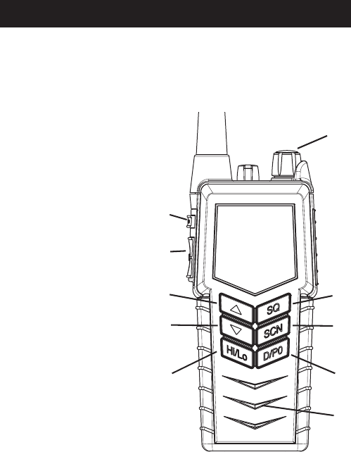
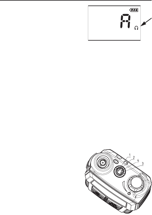
Keys and buttons
1. On/off/volume
2. Light/Lock
3. Push To Talk (PTT)
4. Up key
5. Down key
6. Hi/Lo output power
7. Squelch
8. Scan
9. D/P0 quick channel select
10. Loudspeaker/microphone
1
2
3
4
5
6
7
8
9
10
0740
Operation
6
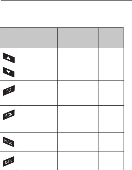
Key presses
Pressing and holding certain keys gives access to additional functions,
shown in the table below.
Key Short press
(1 beep)
Long press
(2 beeps)
Extra long
press
(3 beeps)
Show next available
item in the list (up or
down).
Default: Channel
selection
Run through available
items, or
select tagged channels
P1 (T) or P2 (S).
Run through
available
items if an P1
or P2 channel
is tagged
Activate Squelch
control (Adjust with
up/down arrows).
Monitor function. Open
Squelch completely.
Set period of time in
configuration mode.
1 press: Activate/
terminate Dual watch.
2 presses: Activate
memory scan.
Add/Delete channel
from memory scan.
Toggle between high
and low transmitter
power.
Select channel D. Select preprogrammed
channel P0.
0730
Operation
7
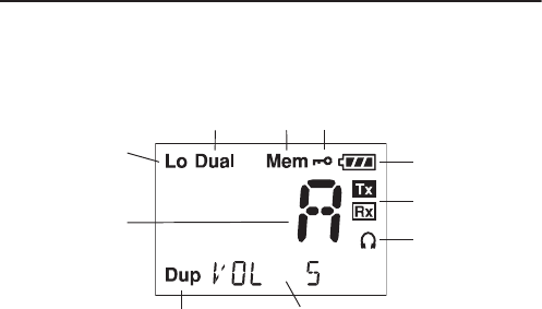
The display
The display holds various fields of information, explained below.
1. Current working channel.
2. “Lo”: Reduced transmitter power.
Full transmitter power is not shown in display.
3. Dual watch activated.
4. Current working channel is marked for scanning.
5. Keypad is locked.
6. Battery level indicator.
7. Transmitting (TX) /Receiving (RX).
8. Accessory is connected.
9. Service line for various purposes. In this example the volume level.
10. Semi-duplex channel.
1
2
345
6
7
8
9
10
0740
Operation
8
Using the UHF
Basic functions
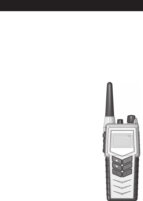
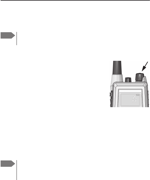
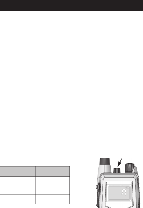
Switching the radio on and off
•To switch the radio on, turn the knob at the top
of the radio clockwise.
The display lights up showing the last used
channel and the battery level.
•To switch the radio off, Turn the knob back
counter-clockwise until it clicks.
Selecting the working channel
• To select channel D, press the D/P0 key.
• To select among all available channels, press S or T on the keypad.
For fast selection, press and hold S or T.
The display shows the currently selected channel. The bottom left corner
of the display shows “Dup” if the channel is a semi-duplex channel.
Note Before using the radio, mount the antenna at the top of the
radio. The antenna is delivered with the radio.
Note Long press on S or T can also be used to select preferred
channels. For information on how to program preferred
channels, see
Configuring the radio
on page 17.
0740
Operation
9
Activating a call
To activate a call to the selected channel, press and
hold the PTT button on the side of the radio.
The radio transmits as long as the PTT button is
pressed. A small Tx sign next to the channel num-
ber indicates when the radio is in transmit mode.
Adjusting the volume
•To increase the volume, turn the on/off knob at the top of the radio
clockwise.
•To decrease the volume, turn the knob counter-clockwise.
The display shows the level of the volume, e.g. “VOL 5”, while it is
adjusted.
Using Squelch control
•To activate Squelch control, press the SQ key.
•To set the Squelch level, press S (closing) or T (opening). The
display shows the Squelch level while it is adjusted, e.g. “SQ 5”.
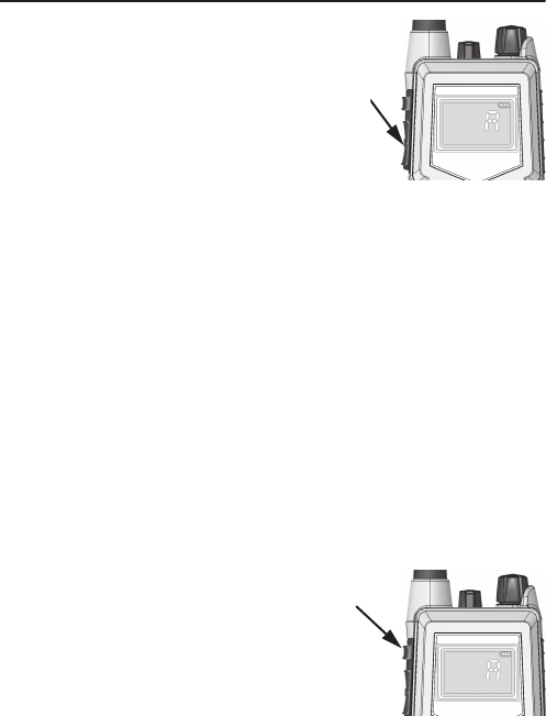
Adjusting the display backlight
•To turn on the backlight, press the
Light/Lock button on the side of the radio.
•To adjust the backlight level, press S or T
within 3 seconds after turning on the light.
The display shows the level while it is
adjusted, e.g. “DIM MED”.
0730

Operation
10
Using Dual watch (requires priority channel is programmed)
•To activate Dual watch, press the SCN key.
The display shows “Dual” at the top and “D” at the bottom right.
The radio toggles between the selected channel and channel D (if
channel D is programmed as the priority channel).
•To terminate Dual watch, press SCN again.
Scanning channels
•To activate scanning memory, press 2 times SCN within ½ a second.
During scanning, the display shows “SC” in the channel field. The
radio toggles between channel D and each of the channels are
marked for scanning (only if a priority channel, e.g. D was
programmed).
•To terminate scanning, press SCN once.
Changing the transmitter power
To change the transmitter power, press the Hi/Lo key. The display shows
“Lo” when power is set to low. Otherwise maximum power is used.
Locking the keypad
•To lock the keypad, press and hold the Light/Lock button. The display
shows a key symbol when the keypad is locked.
•To unlock the keypad, press and hold the Light/Lock button again.
0740

Operation
11
Other functions
Programming the scanning memory
To add a channel to the scanning memory, select the channel and then
press and hold the SCN key until the display shows MEM at the top.
To remove a channel from the scanning memory, select the channel and
then press and hold the SCN key until the MEM sign disappears from the
display.
Low power operation
The radio can be operated in low power mode. In this mode battery life
time is dramatically increased. Up to the first second of a received call
might be lost if this mode is selected. Refer to
SLEEP
on page 18.
Continuous Tone Coded Squelch System
On channels where it is allowed, you can set up selective squelch
opening by sub-tone detection (CTCSS), using the configuration mode
(see
CTCSS
on page 21). Please note that if the radio is operating with
CTCSS on a channel, it is impossible to receive a normal signal on that
channel. For this reason, be very careful not to use CTCSS programmed
channels in emergency situations. Channels programmed with CTCSS will
have a clear identification in the service field, e.g. "CTCSS 22", while
selected. Not all channels are allowed for CTCSS use.
For maritime channels CTCSS is automatically disabled when
•Product is turned off
• A new channel is selected
For private channels, the feature will remain until manually removed.
0740

Operation
12
Scrambler
On channels where it is allowed, you can set up voice scrambling, using
configuration mode (see
SCRM
on page 22).
Please note that if the radio is operating with scrambling on a channel, it
is impossible to communicate with other radios that are not programmed
with the same scrambler code. For this reason, be very careful not to use
scrambled channels in emergency situations. Scrambled channels will
have a clear identification in the service field, e.g. "SCRM 3", while
selected. Not all regions allow the use of voice scrambling.
For maritime channels scrambling is automatically disabled when
• Product is turned off
• A new channel is selected
For private channels, scrambling will remain until manually removed.
Narrow band operation
The radio is prepared for narrow band operation. (see
BAND
on page 22).
Narrow band configuration is indicated with an “n” next to the channel
designator.
Note Prior to any initiation of scrambling, the operator must always
identify the calling station in clear voice (unscrambled) on that
channel. Use of scrambling may also be restricted by national
laws.
0740
Chapter 3
13
Batteries
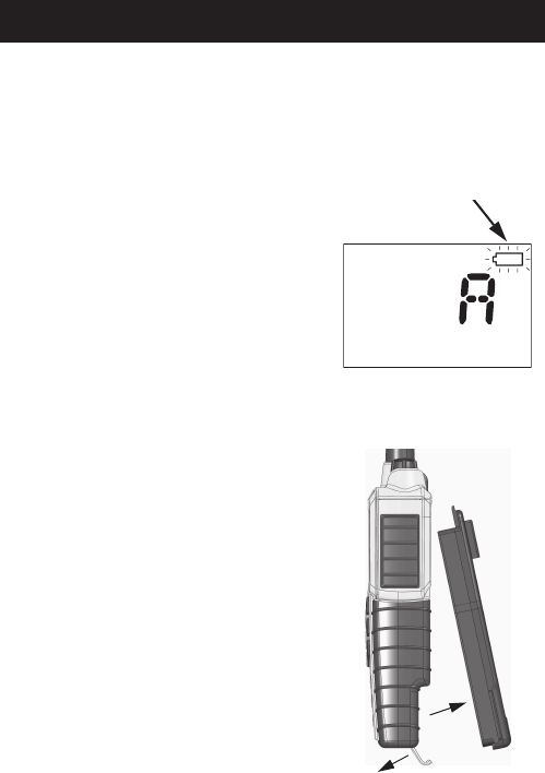
Battery level indication
When the battery level is low, you should recharge the battery.
The radio display shows the battery
status. When the battery symbol is empty
and flashing, the battery should be
recharged as soon as possible.
Removing and inserting the battery pack
To remove the battery pack, do as follows:
1. Open the safety lock as shown.
2. Remove the battery.
To insert the battery pack, attach the battery
and then close the safety lock.
1
2
0730
Batteries
14
The battery chargers
The chargers has two compartments.
CH3507
•A rear compartment only for
storing a spare battery. It does not
have a charger function.
• A front compartment for
recharging the battery alone or
while attached to the radio.
CH3508
• It is possible to charge a battery in
rear compartment simultaneously
with the radio/battery in front.
Installing the charger
Mounting the charger
There are several options for
mounting one or more chargers on a
table or a wall.
For information on dimensions and
screw positions, refer to
Dimensional
drawing, charger
on page 36.
When mounting the charger, make
sure it is placed in a dry place and
away from direct sunlight. The
charger is not waterproof.
0740

Batteries
15
Connecting to power
The charger can be supplied from DC or from AC using an AC/DC
converter.
DC: Connect the 12-24VDC Connection Cable between the DC supply and
the connector on the underside of the charger.
AC: Connect the AC/DC converter to the connector on the underside of the
charger. Then connect the AC/DC converter to the AC outlet.
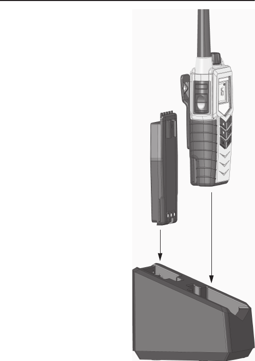
Recharging the battery
To recharge the battery, place the radio1 with battery or the battery alone
in the front position of the charger cradle.
The light indicators on the charger cradle show the status as follows:
• Green light: Power is connected to the charger.
• Slow red flash: Charging in progress.
• Quick red flash (twice per second): Charging error, e.g. battery defect
or temperature out of range.
• Steady red light: Charging completed. Trickle charge mode.
Charging time with emtpy battery: UHF off
approx. 4 hours, UHF on: approx. 5 hours.
The battery indicator on the radio display
indicates if the radio is placed in the
charger while radio and charger are both
powered.
1. The radio may be left on or it may be switched off during the recharge
process
0740

Batteries
16 0730

Chapter 4
17
Configuring the radio
Configuration mode
Entering and using configuration mode
•To enter configuration mode, press and hold the Light/Lock button
while turning on the radio.
The bottom line of the display shows the current menu item/setting.
•To exit configuration mode, turn off the radio or press any key except
S, T and the Light/Lock button.
Using the PTT button or leaving the radio inactive for 10 seconds also
causes the radio to exit configuration mode.
•To change a setting, press S or T.
•To confirm the current setting and go to the next menu item, press the
Light/Lock button.
Note The radio is not operational in configuration mode.
0730

Configuring the radio
18
List of configuration settings
The following settings are available in configuration mode.
Name Values Description
LIGHT MAN Only Light/Lock button activates the backlight.
KEY All keys and buttons, except PTT and volume
control, activate the backlight.
BEEP MAX Status click/beep sound on key press, long
press (settings/programming saved) and
battery alarm. Maximum level.
MIN Status click/beep sound on key press, long
press (settings/programming saved) and
battery alarm. Minimum level.
OFF All beeps off.
VER X.XX.XX Software version. Read-only.
BAT X.XX Battery voltage (V). Read-only.
TEMP XX.X Temperature (°C). Read-only.
SLEEP ON Enable sleep mode (to minimize power
consumption).
Sleeps for periods of 1 second after 15 seconds
of idle mode. Idle mode is: no signal detected
and no operation of the radio.
OFF Disable sleep mode.
0730

Configuring the radio
19
CONTRST 1, 2, 3, 4, 5 Contrast.
1 = lowest and 5 = highest.
SHANG OFF Off. Resumes scanning when signal
disappears.
4, 6, 8, 10 Scan hang time (in seconds) on an active
receiving working channel. The time is
measured from signal detected - remains on
channel even if signal disappears.
RESCN OFF Automatic resume deactivated.
3, 6, 10,
15, 20, 25,
30
Scanning/watch can be automatically resumed
after this time (seconds) if previously
terminated with PTT.
SQ TIME A long press on SQ opens squelch. The squelch
level resumes to setting 3 seconds after SQ is
released.
MAN A long press on SQ opens squelch. The squelch
level resumes to setting as soon SQ is
released.
WORK ON If the default channel D is selected using the
D/P0 key, any push on S or T will select the
working channel active before D/P0 was
pushed.
OFF If on a distress or call channel, any push on
S or T will select the channel next to the
displayed channel.
Name Values Description
0740

Configuring the radio
20
P0 OFF Remove tag “P0” for current working channel.
ON Tag current working channel with “P0”. If
another channel was previously tagged “P0”,
this is overruled.
• The working channel can now be selected
with a long press on “D/P0”.
P1 OFF Remove tag “P1” for current working channel.
ON Tag current working channel with “P1”. If
another channel was previously tagged “P1”,
this is overruled.
• The working channel can now be selected
with a long press on T.
P2 OFF Remove tag “B” for current working channel.
ON Tag current working channel with “P2”. If
another channel was previously tagged “P2”,
this is overruled.
• The working channel can now be selected
with a long press on S.
Name Values Description
0740

Configuring the radio
21
SUBC OFF SUBC disabled. Squelch opens on all received
signals.
1, 2, ..., 38 Sub-tone carrier ID.
Squelch opens if the received signal contains
the desired subtone. During transmission the
sub-tone with the corresponding ID is
generated.
Two radios on the same channel and with the
same sub-tone ID, can reduce unwanted
incoming traffic from other users on the same
channel.
CTCSS OFF CTCSS disabled.
ON Activate CTCSS on working channel. Two
radios on the same channel and with SUBC
enabled, can have a certain level of privacy.
Note that if you choose this option, the radio
immediately exits configuration mode and
starts CTCSS on the working channel.
GROUP SEL Selective Mode. Squelch opens only if the
programmed sub-tone is received in the
signal.
ANY Squelch opens on reception of any of the 38
sub-tones.
Name Values Description
0740

Configuring the radio
22
SCODE OFF No scrambler code is assigned to the channel
(selecting “ON” in the SCRM setting will have
no effect).
1, 2, 3, 4,
5, CC
A selection between 5 fixed sets of scrambler
characteristics, and a custom code (CC), can be
assigned to the channel.
Note that the custom code can be defined in
the service interface.
SCRM OFF Scrambler disabled.
ON Activate scrambling on working channel. Two
radios on the same channel and with
scrambling enabled, can have a certain level of
privacy.
Note that if you choose this option, the radio
immediately exits configuration mode and
starts scrambling on the working channel.
BAND 25.0 Wide band operation selected.
12.5 Narrow band operation selected.
Name Values Description
0740
Chapter 5
23
Equipment and accessories
External equipment
List of equipment
The following equipment can be connected to the radio:
• SAVOX 400E Push-To Talk unit
• SAVOX C500 Fist Mike
• SAVOX NC/400 Noise-com
• SAVOX HC-E Helmet-com
• SAVOX K53004 Helmet unit
• Peltor MT7H79 Headset
We recommend to remove all accessories during emergency use.
All accessories listed might be used when body worn.
Connecting external equipment
Connect the dedicated interface cable between the external equipment
and the top connector on the radio.
Interface cable Order number
For SAVOX 400E 403500-940
For SAVOX C500 403500-950
For Peltor FL5061 403500-951
0740
Equipment and accessories
24
When external equipment is connected
to the radio, the right side of the display
will show a headset.
Impact on radio operation
The external equipment can have a built-in PTT, speaker and
microphone. Thus connecting it to the radio will have the following
impact on the radio operation:
• If a microphone is built into the detected external equipment, the
external equipment microphone is used, and the internal radio
microphone is disabled.
• If a speaker or earpiece is built into the detected external equipment,
the external equipment sound device is used, and the internal radio
speaker is disabled.
• If a PTT or VOX is built into the detected external equipment, the
external equipment PTT control is used, and the radio PTT button is
disabled.
Accessorie connector
Pin 1. Loudspeaker,
minimum 8 ohm impedance.
Pin 2. Accessory power,
5V maximum 0.03A.
Pin 3. Microphone input,
Ri = 2.2kohm, 3V phantom power.
Pin 4. GND.
0740

Equipment and accessories
25
Accessories
List of accessories
The following accessories are delivered with your radio:
Batteries, charger, AC/DC Converter and 12VDC Connection are described
in
Batteries
on page 13
.
To mount the antenna, simply screw it into the threaded bush at the top
of the radio.
Use of lanyard is only for hand held operation. Put it around the wrist to
prevent dropping the radio.
Accessory Part number
Rechargeable battery, B3502 403502A
Charger, CH3507 403507A
AC/DC converter, length 150cm (100-240V~ /12VDC out) 88-125538
12-24VDC Connection cable, length 150cm 37-124381
Belt clip 62-124320
Antenna 88-125662
Lanyard 41-124375
SP3550 User Manual (this manual) 98-124308
0740