Tiger Products Co Ltd M105X S Users Manual COVER PAGE.PMD
!! Tiger-26 Tiger Products Lawn Mower Manuals - Lawn Mower Manuals – The Best Lawn Mower Manuals Collection
M105XS to the manual 17aa6832-a4ec-45bb-9c2c-91644ef69b31
2015-02-02
: Tiger-Products-Co-Ltd Tiger-Products-Co-Ltd-M105X-S-Users-Manual-486101 tiger-products-co-ltd-m105x-s-users-manual-486101 tiger-products-co-ltd pdf
Open the PDF directly: View PDF ![]() .
.
Page Count: 176 [warning: Documents this large are best viewed by clicking the View PDF Link!]

PARTS LISTING WITH
MOUNTING AND OPERATING
INSTRUCTIONS
SIDE ROTARY
ASSEMBLIES
KUBOTA M105X/S
CAB / WOC
06070001
Tiger Corporation
3301 N. Louise Ave.
Sioux Falls, SD 57107
1-800-843-6849
1-605-336-7900
www.tiger-mowers.com
Current as of 07/12/2010

TO THE OWNER / OPERATOR / DEALER
All implements with moving parts are potentially hazardous. There is no substitute for a cautious,
safe-minded operator who recognizes the potential hazards and follows reasonable safety practices.
The manufacturer has designed this implement to be used with all its safety equipment properly
attached to minimize the chance of accidents.
BEFORE YOU START!! Read the safety messages on the implement and shown in this manual.
Observe the rules of safety and use common sense!
READ AND UNDERSTAND THIS MANUAL! Non–English speaking operators will need to GET
THE MANUAL TRANSLATED as needed!
Warranty Information: Read and understand the complete Warranty Statement found in this manual. Fill out the
Warranty Registration form in full and return it within 90 days. Make certain the Serial Number of the machine is
recorded on the Warranty Card, and form that you retain.

FORWARD
This manual contains information about many features of the Tiger mowing
and roadside maintenance equipment. Some of these include: Safety
precautions, Assembly instructions, Operations, Maintenance and Parts.
This manual will also assist you in the proper break-in, daily care, and
troubleshooting of your new mower.
We recommend that you read carefully the entire manual before operating
the unit. Also, time spent in becoming fully acquainted with its performance
features, adjustments, and maintenance schedules will be repaid in a long
and satisfactory life of the equipment.
Troubleshooting - Please, before you call, help us to help you!
Please look at the equipment to observe what is happening, then:
• Classify the problem
• Hydraulic, electrical or mechanical - Read the trouble shooting section
• Tractor or Truck chassis - Contact vehicle dealer
• If unable to correct the problem yourself, contact your local Tiger Dealer after
gathering:
• Machine model _______________________
• Serial number ________________________
• Dealer name _________________________
• Detailed information about the problem including results of troubleshooting
Attention Owner / Operator / Dealer: It is your obligation to read, and
understand, the warranty information section located at the back of this
manual denoting that the purchaser understands the safety issues relating
to this machine and has received and will read a copy of this manual.
If at any time, you have a service problem with your Tiger mower, Contact
your local dealer for service and parts needed.
MANUFACTURED BY: DISTRIBUTED BY:
Tiger Corporation _____________________
3301 N. Louise Ave. _____________________
Sioux Falls, SD 57107 1-_____-_____-________
1-800-843-6849 1-_____-_____-________
1-605-336-7900
www.tiger-mowers.com

TABLE OF CONTENTS
SAFETY_____________________________________________ 1-1
Safety Information__________________________________ 1-2
ASSEMBLY / MOUNTING SECTION_______________________ 2-1
OPERATION SECTION_________________________________ 3-1
MAINTENANCE SECTION______________________________ 4-1
PARTS SECTION_____________________________________ 5-1
Parts Ordering Guide_______________________________ 5-2
Parts Table of Contents______________________________ 5-3
Common Parts Section____________________________ 6-1
WARRANTY INFORMATION_____________________________ 7-1
This symbol means:
CAUTION – YOUR SAFETY IS AT RISK!
When you see this symbol, read and
follow the associated instructions carefully
or personal injury or damage may result.
Tiger is a registered trademark.

SAFETY
SECTION
Side Rtry Safety Section 1-2
SAFETY
SAFETY
Indicates an imminently hazardous situation that, if not avoided, WILL result in
DEATH OR VERY SERIOUS INJURY.
Indicates an imminently hazardous situation that, if not avoided, COULD result
in DEATH OR SERIOUS INJURY.
Indicates an imminently hazardous situation that, if not avoided, MAY result in
MINOR INJURY.
Identifies special instructions or procedures that, if not strictly observed, could
result in damage to, or destruction of the machine, attachments or the
enviroment.
NOTE: Identifies points of particular interest for more efficient or convienient operation
or repair. (SG-1)
General Safety Instructions and Practices
A safe and careful operator is the best operator. Safety is of primary importance to the
manufacturer and should be to the owner / operator. Most accidents can be avoided by
being aware of your equipment, your surroundings, and observing certain precautions.
The first section of this manual includes a list of Safety Messages that, if followed, will help
protect the operator and bystanders from injury or death. Read and understand these
Safety Messages before assembling, operating or servicing this mower. This equipment
should only be operated by those persons who have read the Manual, who are responsible
and trained, and who know how to do so safely and responsibly.
The Safety Alert Symbol combined with a Signal Word, as seen below, is used
throughout this manual and on decals which are attached to the equipment. The
Safety Alert Symbol means: “ATTENTION! BECOME ALERT! YOUR SAFETY
IS INVOLVED!” The symbol and signal word are intended to warn the owner /
operator of impending hazards and the degree of possible injury when operating
this equipment.
Practice all usual and customary safe working precautions and
above all -- remember safety is up to YOU! Only YOU can
prevent serious injury or death from unsafe practices.
READ, UNDERSTAND, and FOLLOW the following Safety Messages.
Serious injury or death may occur unless care is taken to follow the
warnings and instructions stated in the Safety Messages. Always use
good common sense to avoid hazards. (SG-2)
IMPORTANT!
Side Rtry Safety Section 1-3
SAFETY
SAFETY
!
Si no lee Ingles, pida ayuda a alguien que
si lo lea para que le traduzca las medidas
de seguridad. (SG-3)
PELIGRO! LEA EL
INSTRUCTIVO!
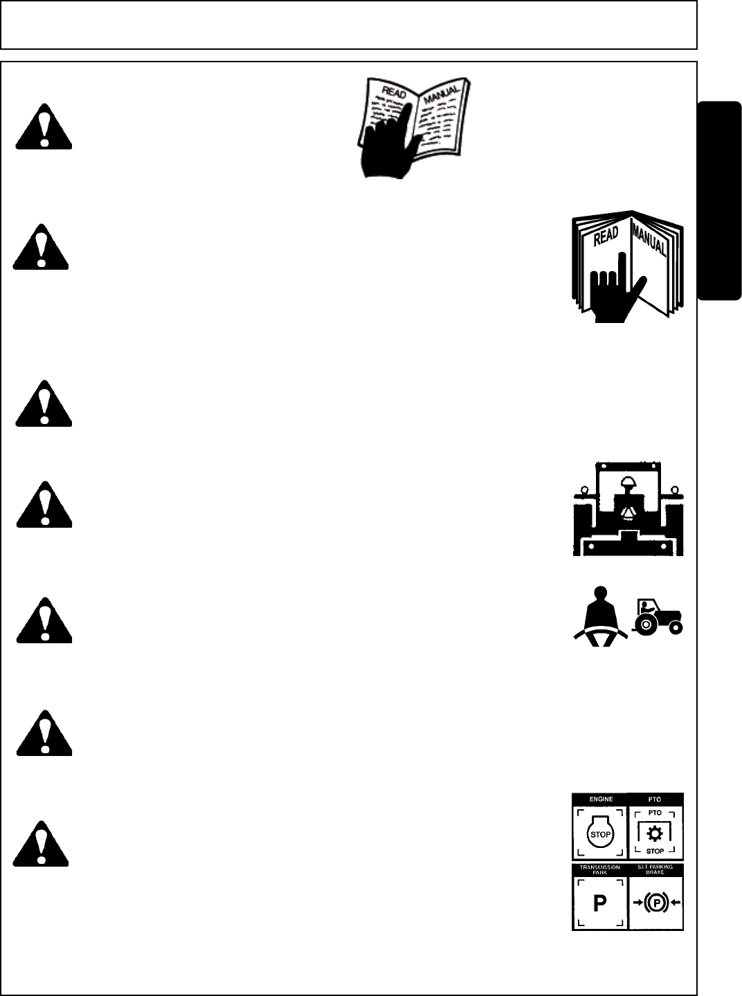
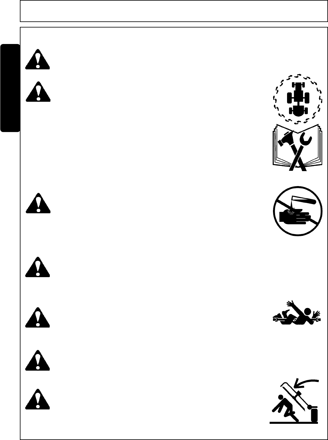
DANGER! Never operate the Tractor or Implement until you have read and
completely understand this Manual, the Tractor Operator’s Manual,
and each of the Safety Messages found in the Manual or on the Tractor
and Implement. Learn how to stop the tractor engine suddenly in an
emergency. Never allow inexperienced or untrained personnel too
operate the Tractor and Implement without supervision. Make sure
the operator has fully read and understood the manuals prior to
operation. (SG-4)
WARNING! Make certain that the “Slow Moving Vehicle” (SMV) sign is installed in
such a way as to be clearly visible and legible. When transporting the
Equipment use the Tractor flashing warning lights and follow all local traffic
regulations. (SG-6)
WARNING! Operate this Equipment only with a Tractor equipped with an
approved roll-over-protective system (ROPS). Always wear seat
belts. Serious injury or even death could result from falling off the
tractor--particularly during a turnover when the operator could be
pinned under the ROPS. (SG-7)
WARNING! Do not modify or alter this Implement. Do not permit anyone to modify
or alter this Implement, any of its components or any Implement
function. (SG-8)
DANGER! BEFORE leaving the tractor seat, always engage the brake and/or set
the tractor transmission in parking gear, disengage the PTO, stop the
engine, remove the key, and wait for all moving parts to stop. Place the
tractor shift lever into a low range or parking gear to prevent the tractor
from rolling. Never dismount a Tractor that is moving or while the engine
is running. Operate the Tractor controls from the tractor seat only.
(SG-9)
WARNING! Always maintain the safety decals in good readable condition. If the
decals are missing, damaged, or unreadable, obtain and install replace-
ment decals immediately. (SG-5)
Side Rtry Safety Section 1-4
SAFETY
SAFETY
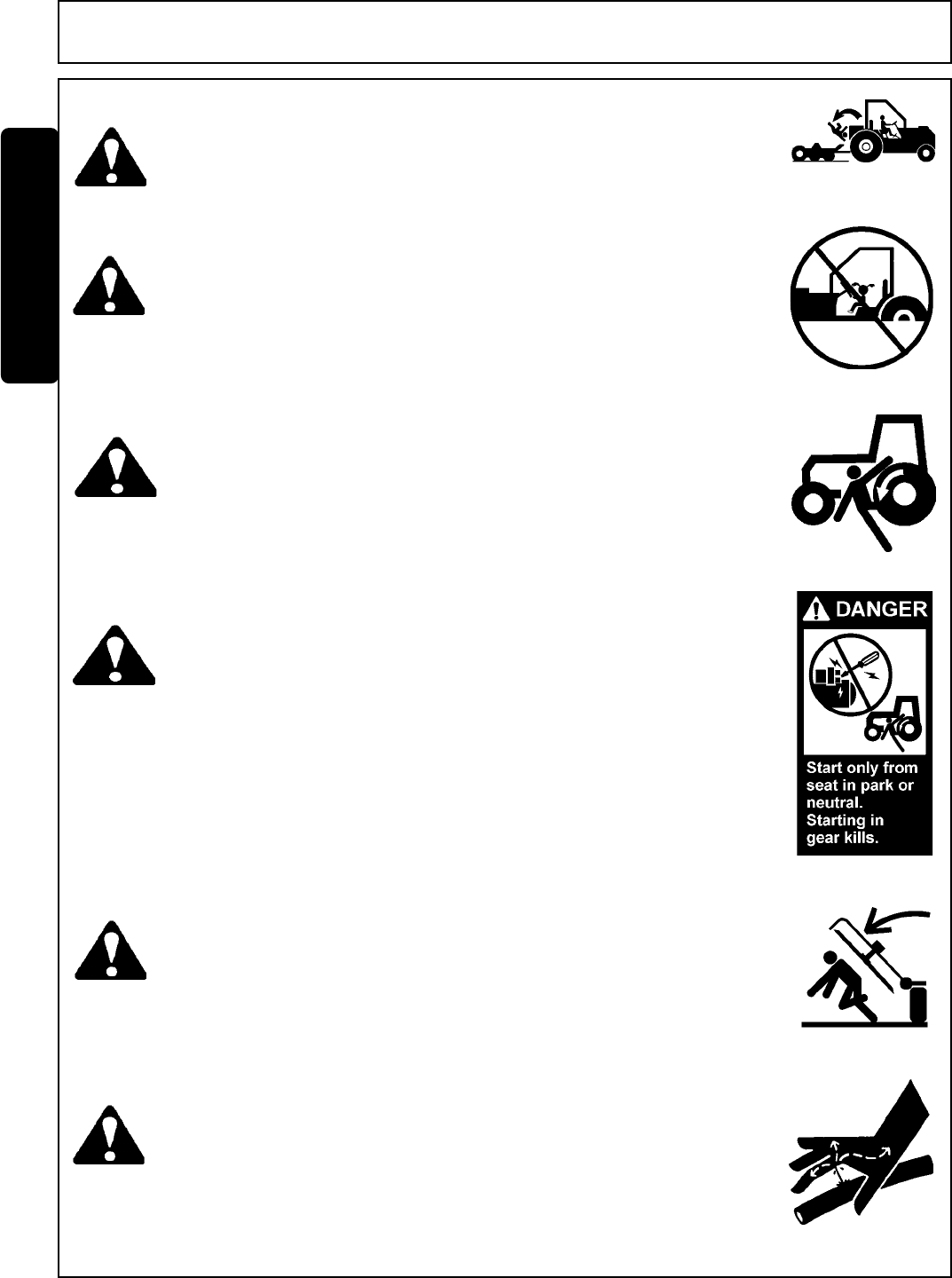
DANGER! Never allow children or other persons to ride on the Tractor or Implement.
Falling off can result in serious injury or death.
(SG-10)
DANGER! Never allow children to operate or ride on the Tractor or Implement.
(SG-11)
WARNING! Do not mount the Tractor while the tractor is moving. Mount the Tractor
only when the Tractor and all moving parts are completely stopped.
(SG-12)
DANGER! Start tractor only when properly seated in the Tractor seat. Starting a
tractor in gear can result in injury or death. Read the Tractor operators
manual for proper starting instructions. (SG-13)
DANGER! Never work under the Implement, the framework, or any lifted compo-
nent unless the Implement is securely supported or blocked up to
prevent sudden or inadvertent falling which could cause serious injury
or even death. (SG-14)
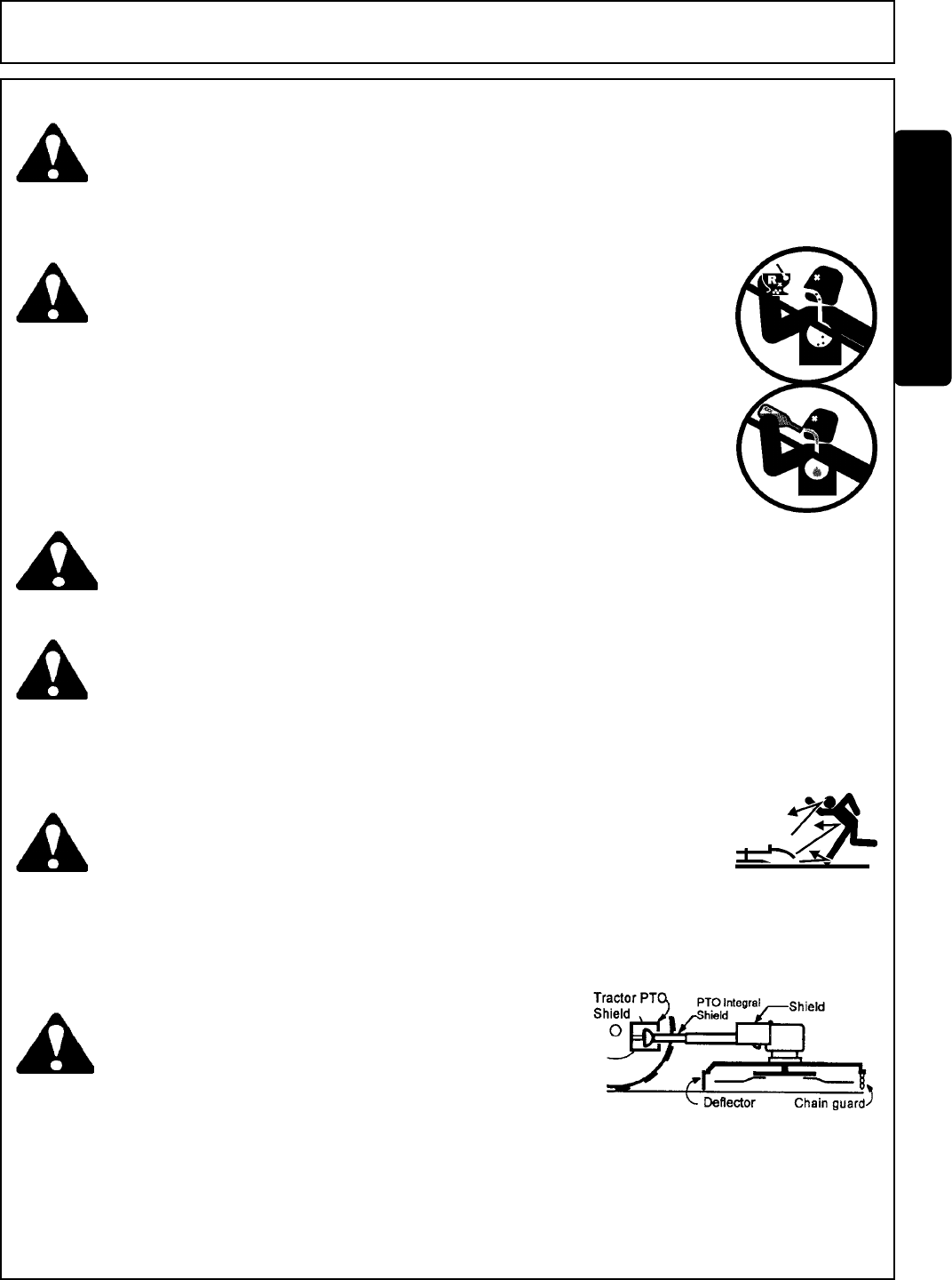
DANGER! Do not operate this Equipment with hydraulic oil leaking. Oil is
expensive and its presence could present a hazard. Do not check for
leaks with your hand! Use a piece of heavy paper or cardboard. High-
pressure oil streams from breaks in the line could penetrate the skin
and cause tissue damage including gangrene. If oil does penetrate the
skin, have the injury treated immediately by a physician knowledge-
able and skilled in this procedure. (SG-15)
Side Rtry Safety Section 1-5
SAFETY
SAFETY
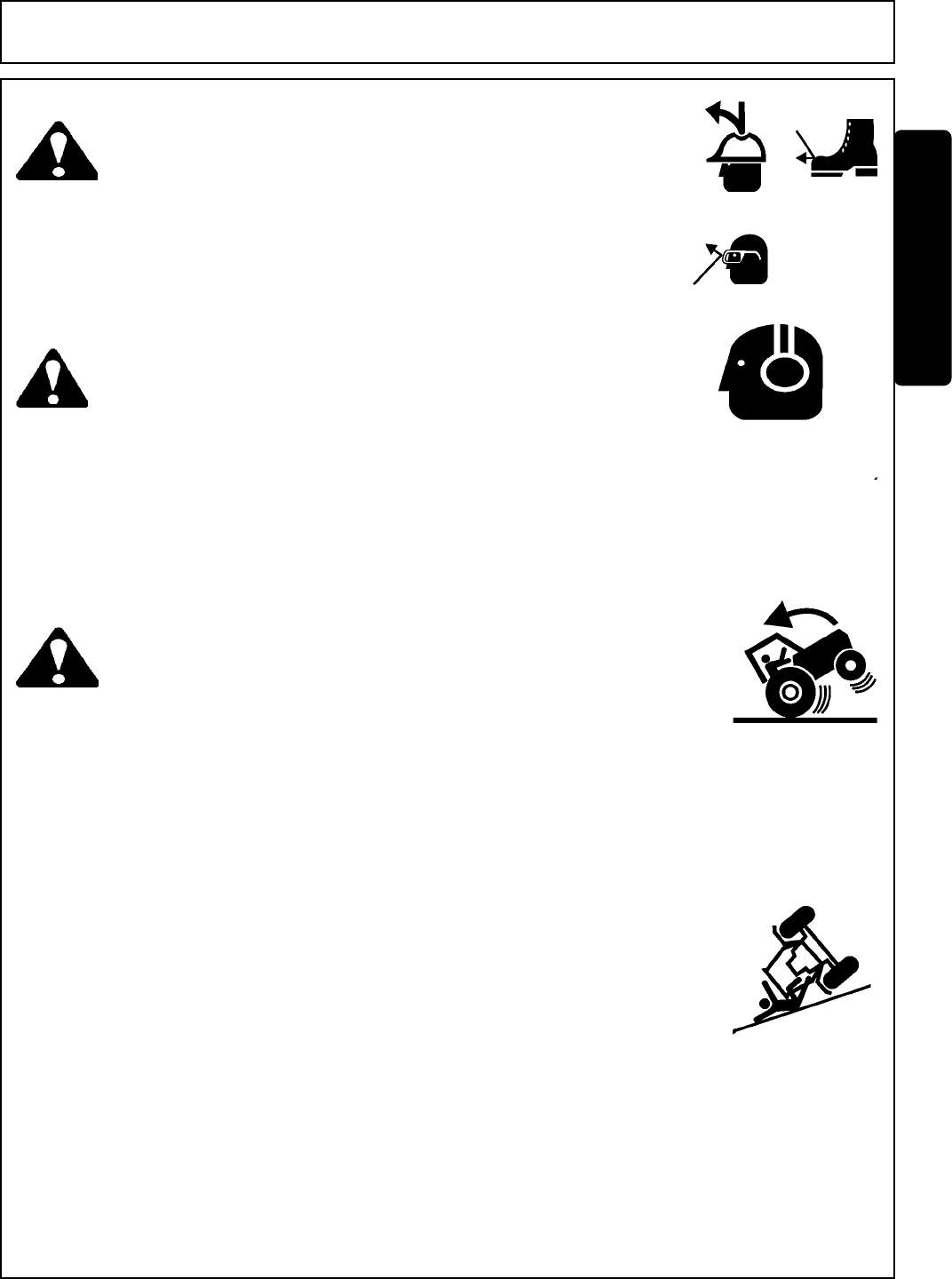
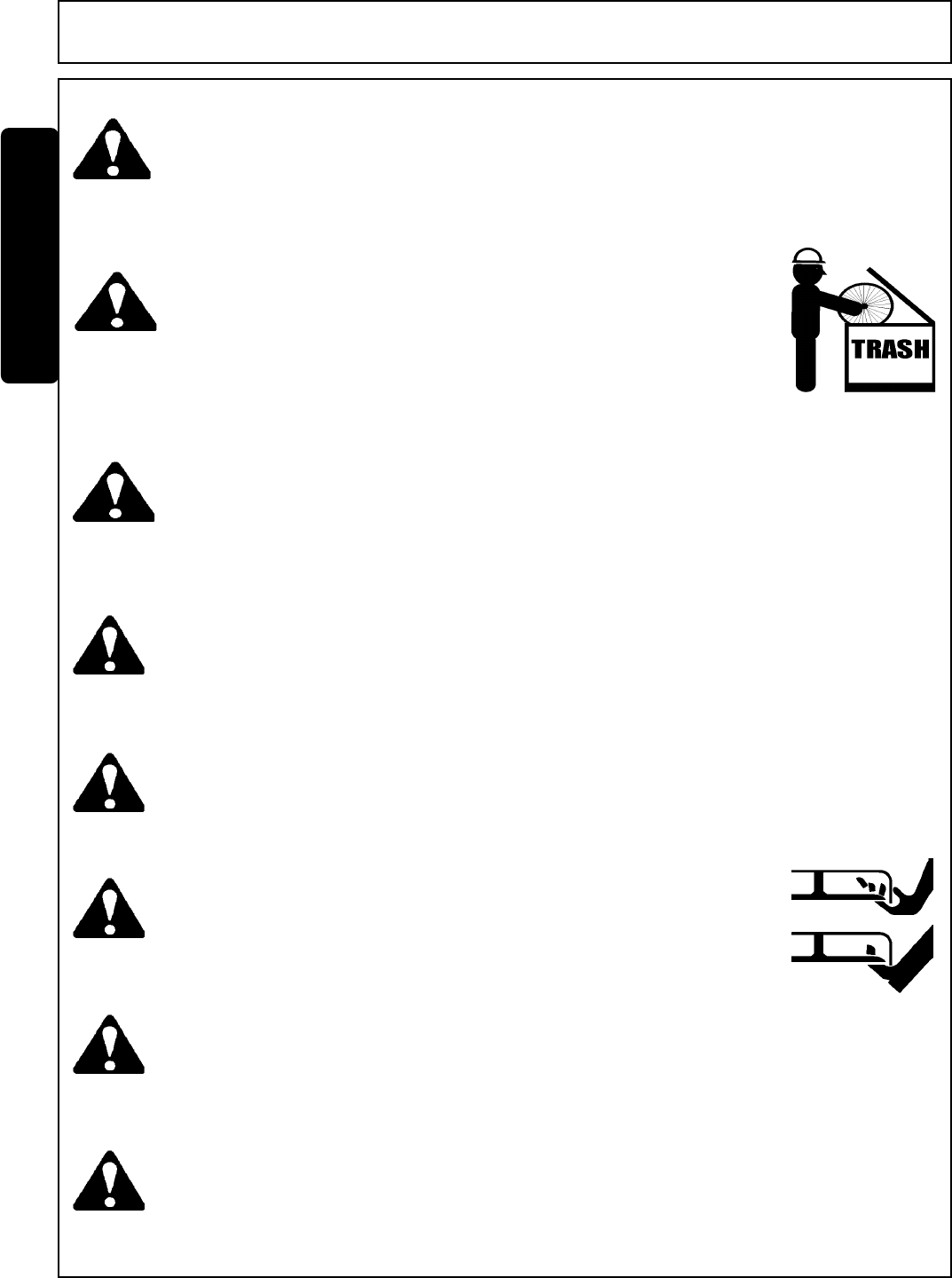
WARNING! The operator and all support personnel should wear hard hats,
safety shoes, safety glasses, and proper hearing protection at all
times for protection from injury including injury from items thrown by
the equipment. (SG-16)
WARNING! Transport only at safe speeds. Serious accidents and injuries can
result from operating this equipment at unsafe speeds. Understand
the Tractor and Implement and how it handles before transporting
on streets and highways. Make sure the Tractor steering and brakes
are in good condition and operate properly.
Before transporting the Tractor and Implement, determine the safe
transport speeds for you and the equipment. Make sure you abide by
the following rules:
Be aware of the operating conditions. Do not operate the Tractor
with weak or faulty brakes. When operating down a hill or on wet or
rain slick roads, the braking distance increases: use extreme care
and reduce your speed. When operating in traffic always use the
Tractor’s flashing warning lights and reduce your speed. Be aware of
traffic around you andwatch out for the other guy. (SG-19)
Test the equipment at a slow speed in turns. Increase the speed
through the turn only after you determine that it is safe to oper-
ate
at a higher speed. Use extreme care and reduce your speed
when
turning sharply to prevent the tractor and implement from turn-
ing
over. Determine the maximum safe turning speed for you and
this equipment before operating on roads or uneven ground.
Only transport the Tractor and Implement at the speeds that you
have determined are safe and which allow you to properly con-
trol the equipment.
Test the tractor at a slow speed and increase the speed slowly.
Apply the Brakes smoothly to determine the stopping
characteristics of the Tractor and Implement.
As you increase the speed of the Tractor the stopping distance
increases. Determine the maximum safe transport speed for
you and this Equipment.
2.
1.
3.
CAUTION! PROLONGED EXPOSURE TO LOUD NOISE MAY CAUSE PER-
MANENT HEARING LOSS! Tractors with or without an Implement
attached can often be noisy enough to cause permanent hearing
loss. We recommend that you always wear hearing protection if the
noise in the Operator’s position exceeds 80db. Noise over 85db
over an extended period of time will cause severe hearing loss.
Noise over 90db adjacent to the Operator over an extended period of
time will cause permanent or total hearing loss. Note: Hearing loss
from loud noise [from tractors, chain saws, radios, and other such
sources close to the ear] is cumulative over a lifetime without hope
of natural recovery. (SG-I7)
Side Rtry Safety Section 1-6
SAFETY
SAFETY
WARNING! Periodically inspect all moving parts for wear and replace when
necessary with authorized service parts. Look for loose fasteners,
worn or broken parts, and leaky or loose fittings. Make sure all pins
have cotter pins and washers. Serious injury may occur from not
maintaining this machine in good working order. (SG-21)
WARNING! Always read carefully and comply fully with the manufacturers instruc-
tions when handling oil, solvents, cleansers, and any other chemical
agent. (SG-22)
DANGER! Never run the tractor engine in a closed building or without adequate
ventilation. The exhaust fumes can be hazardous to your health.
(SG-23)
DANGER! KEEP AWAY FROM ROTATING ELEMENTS to prevent entanglement
and possible serious injury or death. (SG-24)
DANGER! Never allow children to play on or around Tractor or Implement. Children
can slip or fall off the Equipment and be injured or killed. Children can
cause the Implement to shift or fall crushing themselves or others. (SG-25)
WARNING! Never attempt to lubricate, adjust, or remove material from the
Implement while it is in motion or while tractor engine is running. Make
sure the tractor engine is off before working on the Implement.
(SG-20)
DANGER! DO NOT allow any person under a folded wing unless wing is securely
locked up or supported. DO NOT approach the Implement unless the
Tractor is turned off and all motion has ceased. Never work under the
frame work, or any lifted component unless the implement is securely
supported or blocked up. A sudden or inadvertent fall by any of these
components could cause serious injury or even death. (STI-3)
Side Rtry Safety Section 1-7
SAFETY
SAFETY
CAUTION! On a fully-assembled unit, do not remove the Wing Retaining Strap
until hoses are attached to the tractor and the Wing Cylinders are
filled with oil. Lower the Wings slowly and carefully. Keep bystand-
ers away during operations. (STI-5)
DANGER! NEVER use drugs or alcohol immediately before or while operating the
Tractor and Implement. Drugs and alcohol will affect an operator’s
alertness and coordination and therefore affect the operator’s ability to
operate the equipment safely. Before operating the Tractor or Imple-
ment, an operator on prescription or over-the-counter medication must
consult a medical professional regarding any side effects of the medi-
cation that would hinder their ability to operate the Equipment safely.
NEVER knowingly allow anyone to operate this equipment when their
alertness or coordination is impaired. Serious injury or death to the
operator or others could result if the operator is under the influence of
drugs or alcohol. (SG-27)
WARNING! Mow only in conditions where you have clear visibility in daylight or with
adequate artificial lighting. Never mow in darkness or foggy conditions
where you cannot clearly see at least 100 yards in front and to the sides of
the tractor and mower. Make sure that you can clearly see and identify
passersby, steep slopes, ditches, drop-offs, overhead obstructions, power
lines, debris and foreign objects. If you are unable to clearly see this type
of items discontinue mowing. (SGM-1)
DANGER! There are obvious and hidden potential hazards in the operation of this
Mower. REMEMBER! This machine is often operated in heavy brush
and in heavy weeds. The Blades of this Mower can throw objects if
shields are not properly installed and maintained. Serious injury or
even death may occur unless care is taken to insure the safety of the
operator, bystanders, or passersby in the area. Do not operate this
machine with anyone in the immediate area. Stop mowing if anyone
is within 100 yards of mower. (SGM-2)
DANGER! Operate the Tractor and/or Implement controls only while properly seated
in the Tractor seat with the seat belt securely fastened around you.
Inadvertent movement of the Tractor or Implement may cause serious
injury or death. (SG-29)
DANGER! All Safety Shields, Guards and Safety devices including
(but not limited to) - the Deflectors, Chain Guards, Steel
Guards, Gearbox Shields, PTO integral shields , and
Retractable Door Shields should be used and main-
tained in good working condition. All safety devices
should be inspected carefully at least daily for missing
or broken components. Missing, broken, or worn items
must be replaced at once to reduce the possibility of
injury or death from thrown objects, entanglement, or
blade contact. (SGM-3)
Side Rtry Safety Section 1-8
SAFETY
SAFETY
DANGER! The rotating parts of this machine have been designed and tested for
rugged use. However, the blades could fail upon impact with heavy,
solid objects such as metal guard rails and concrete structures. Such
impact could cause the broken objects to be thrown outward at very
high velocities. To reduce the possibility of property damage, serious
injury, or even death, never allow the cutting blades to contact such
obstacles. (SGM-4)
WARNING! Many varied objects, such as wire, cable, rope, or chains, can become
entangled in the operating parts of the mower head. These items could
then swing outside the housing at greater velocities than the blades. Such
a situation is extremely hazardous and could result in serious injury or
even death. Inspect the cutting area for such objects before mowing.
Remove any like object from the site. Never allow the cutting blades to
contact such items. (SGM-6)
WARNING! Mow at the speed that you can safely operate and control the tractor and
mower. Safe mowing speed depends on terrain condition and grass type,
density, and height of cut. Normal ground speed range is from 0 to 5 mph.
Use slow mowing speeds when operating on or near steep slopes,
ditches, drop-offs, overhead obstructions, power lines, or when debris and
foreign objects are to be avoided. (SGM-7)
WARNING! Extreme care should be taken when operating near loose objects such
as gravel, rocks, wire, and other debris. Inspect the area before
mowing. Foreign objects should be removed from the site to prevent
machine damage and/or bodily injury or even death. Any objects that
cannot be removed must be clearly marked and carefully avoided by
the operator. Stop mowing immediately if blades strike a foreign
object. Repair all damage and make certain rotor or blade carrier is
balanced before resuming mowing. (SGM-5)
WARNING! Avoid mowing in reverse direction when possible. Check to make sure there
are no persons behind the mower and use extreme care when mowing in
reverse. Mow only at a slow ground speed where you can safely operate and
control the tractor and mower. Never mow an area that you have not
inspected and removed debris or foreign material. (SGM-8)
WARNING! Do not put hands or feet under mower decks. Blade Contact can result
serious injury or even death. Stay away until all motion has stopped and
the decks are securely blocked up. (SGM-9)
DANGER! Replace bent or broken blade with new blades. NEVER ATTEMPT TO
STRAIGHTEN OR WELD ON BLADES SINCE THIS WILL LIKELY
CRACK OR OTHERWISE DAMAGE THE BLADE WITH SUBSE-
QUENT FAILURE AND POSSIBLE SERIOUS INJURY FROM THROWN
BLADES. (SGM-10)
WARNING! Do not mow with two machines in the same area except with Cab tractors
with the windows closed. (SGM-11)
Side Rtry Safety Section 1-9
SAFETY
SAFETY
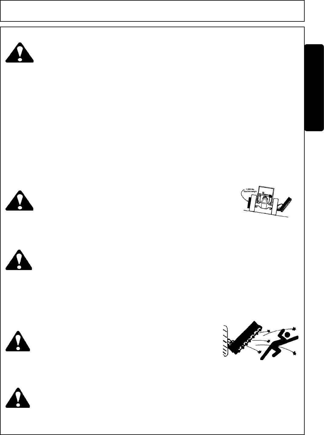
DANGER! Rotary Mowers are capable under adverse conditions of throwing
objects for great distances (100 yards or more) and causing
serious injury or death. Follow safety messages carefully.
STOP MOWING IF PASSERSBY ARE WITHIN 100 YARDS UN-
LESS: -Front and Rear Deflectors are installed and in good,
working condition;
-Mower Head is running close to and parallel to the ground
without exposed Blades;
-Passersby are outside the existing thrown-object zone;
-All areas have been thoroughly inspected and all foreign
material such as rocks, cans, glass, and general debris
has been removed.
NOTE: Where there are grass and weeds high enough to hide debris
that could be struck by the blades, the area should be: in-
spected and large debris removed, mowed at an intermediate
height, inspected closely with any remaining debris removed,
and mowed again at desired final height. (SBM-1)
DANGER! Use extreme caution when raising the Mower head. Stop the Blades
from turning when the Mower Head is raised and passersby are within
100 yards. Raising the Mower head exposes the Cutting Blades
which creates a potentially serious hazard and can cause serious
injury by objects thrown from the Blades or by contact with the Blades.
(SBM-2)
WARNING! Each Rear Wheel must have a minimum of 1,000 pounds contact with
the surface to prevent lateral instability and possible tip-over which
could result in serious bodily injury or even death. Widen the wheel
tread and add weights if needed. Refer to the mounting instructions
or call Customer Service if you need assistance with Couterweight
Procedure. (SFL-3)
WARNING! Do not operate Mower if excessive vibration exists. Shut down PTO
and the Tractor engine. Inspect the Mower to determine the source
of the vibration. If Mower blades are missing or damaged replace
them immediately. Do not operate the mower until the blades have
been replaced and the Mower operates smoothly. Operating the
Mower with excessive vibration can result in component failure and
broken objects to be thrown outward at very high velocities. To reduce
the possibility of property damage, serious injury, or even death, never
allow the Mower to be operated with blades missing. (SFL-4)
WARNING! Do not let the Blades turn when the Mower Deck is raised for any
reason, including clearance or for turning. Raising the Mower
deck exposes the Cutting Blades which creates a potentially
serious hazard and could cause serious injury or even death from
objects thrown from the Blades. (SRM-7)
Side Rtry Safety Section 1-10
SAFETY
SAFETY
WARNING! Never leave the Tractor and Implement unattended while the Implement is
in the lifted position. Accidental operation of lifting lever or a hydraulic
failure may cause sudden drop of unit with injury or death by crushing.
To properly park the implement when disconnecting it from the tractor,
lower the stand and put the retaining pin securely in place, or put a secure
support under the A-Frame. Lower the implement carefully to the ground.
Do not put hands or feet under lifted components. (S3PT-1)
WARNING! Relieve hydraulic pressure prior to doing any maintenance or repair
work on the Implement. Place the Mower Head on the ground or
securely supported on blocks or stands, disengage the PTO, and turn
off the engine. Push and pull the control Levers or Joystick several
times to relieve pressure prior to starting any maintenance or repair
work. (SBM-6)
DANGER! Always disconnect the wire leads from the mower valve solenoid before
performing service on the Tractor or Mower. Use caution when working
on the Tractor or Mower. Tractor engine must be stopped before
working on Mower or Tractor. The Mower Blades could inadvertently be
turned on without warning and cause immediate dismemberment, injury
or death. (SBM-12)
WARNING! Use extreme care when lowering or unfolding the implement’s wings.
Make sure no bystanders are close by or underneath the wings. Allow
ample clearance around the implement when folding or unfolding the
wings. Use extreme caution around buildings or overhead power lines.
(S3PT-
5)
WARNING! Relieve hydraulic pressure prior to doing any maintenance or repair work
on the Implement. Place the Implement on the ground or securely
blocked up, disengage the PTO, and turn off the tractor engine. Push
and pull the Remote Cylinder lever in and out several times prior to
starting any maintenance or repair work. (S3PT-9)
DANGER! This Implement is wider than the Tractor. Be careful when operating
or transporting this equipment to prevent the Implement from running
into or striking sign posts, guard rails, concrete abutments or other
solid objects. Such an impact could cause the Implement and Tractor
to pivot violently resulting in loss of steering control, serious injury, or
even death. Never allow the Implement to contact obstacles. (S3PT-
12)
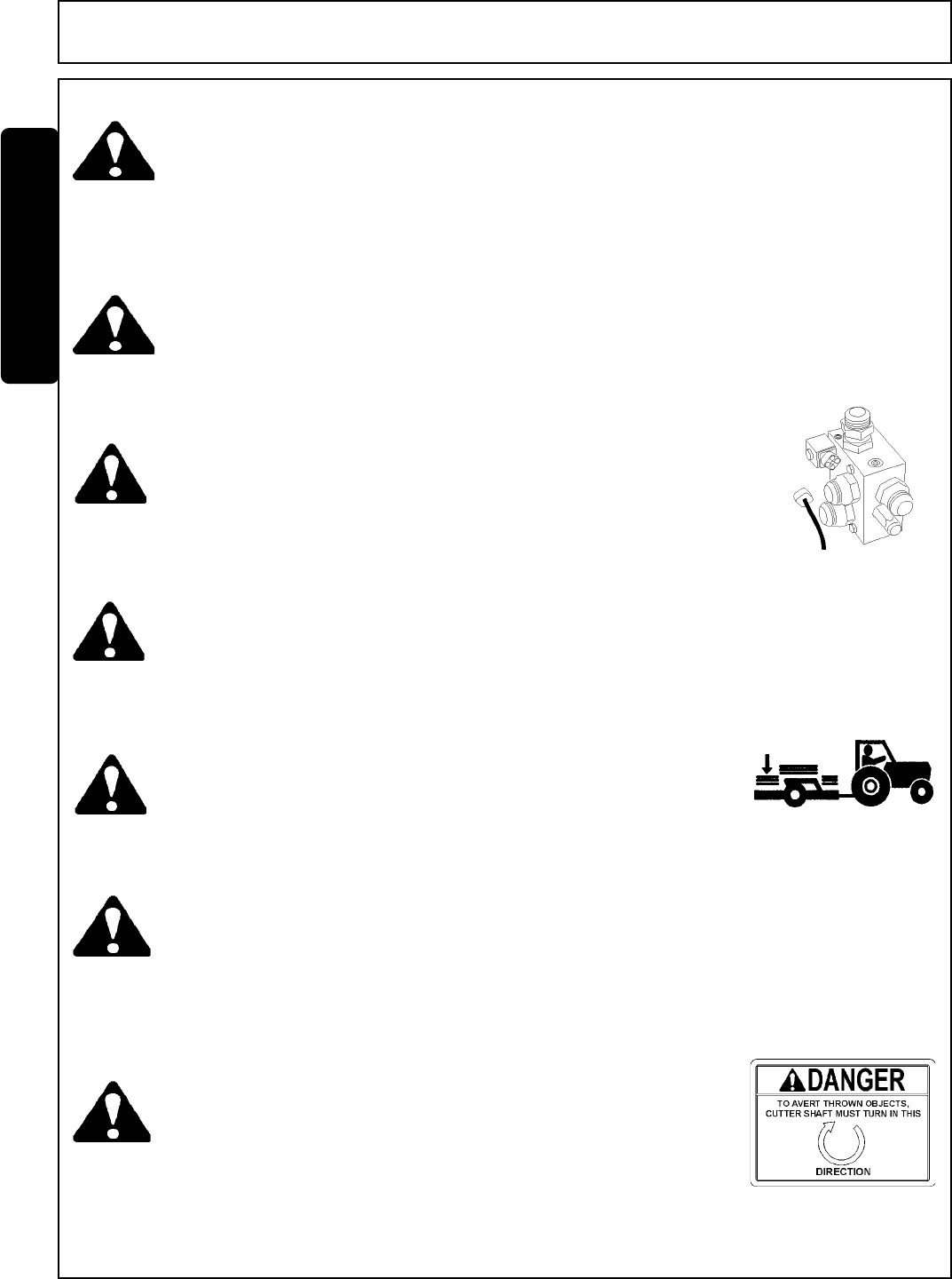
DANGER! The flail cutter shaft is designed for standard rotation(same rotation
as the tractor wheel during forward travel). Never operate the cutter
shaft in the reverse rotation. Operating this mower in reverse
rotation may cause objects to be thrown out the front of the mower
head.

Side Rtry Safety Section 1-11
SAFETY
SAFETY
WARNING! The rotating parts of this machine continue to rotate even after the Tractor
has been turned off. The operator should remain in his seat for 60
seconds after the brake has been set, the PTO disengaged, the tractor
turned off, and all evidence of rotation has ceased. (SBM-5)
“Wait a minute...Save a life!”
WARNING! Engine Exhaust, some of its constituents, and certain components
contain or emit chemicals known to the state of California to cause
cancer and birth or other reproductive harm.
WARNING! Battery post, terminals and related accessories contain lean and lead
compounds, chemicals known to the state of California to cause cancer
and birth or other reproductive harm. Wash hands after handling!
In addition to the design and configuration of this Implement, including Safety Signs and Safety Equipment, hazard
control and accident prevention are dependent upon the awareness, concern, prudence, and proper training of
personnel involved in the operation, transport, maintenance, and storage of the machine. Refer also to Safety
Messages and operation instruction in each of the appropriate sections of the Tractor and Equipment Manuals.
Pay close attention to the Safety Signs affixed to the Tractor and Equipment. (SG-18)
Tiger mowers use balanced and matched system components for blade carriers, blades, cutter-shafts, knives, knife hang-
ers, rollers, drive-train components and bearings. These parts are made and tested to Tiger specifications. Non-genuine
“will fit” parts do not consistently meet these specifications. The use of “will fit” parts may reduce mower performance,
void mower warranties and present a safety hazard. Use genuine Tiger mower parts for economy and safety.
SEE YOUR DEALER
Side Rtry Safety Section 1-12
SAFETY
SAFETY

Side Rtry Safety Section 1-13
SAFETY
SAFETY
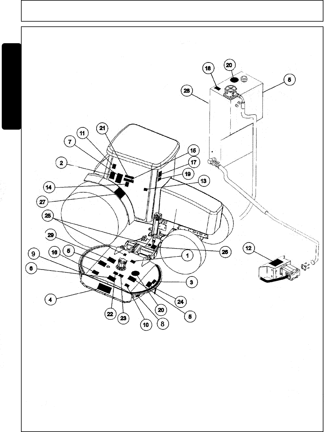
ITEM PART NO. QTY. DESCRIPTION
1 22839 1 INSTRUCT Don Not Lubricate With Automatic Grease Gun
2 22840 1 WARNING Foreign Objects Contacted
3 24028 1 WARNING Inspect Rear Flap
4 31522 1 LOGO TIGER MOWERS
5 31523 3 LOGO TIGER MOWERS
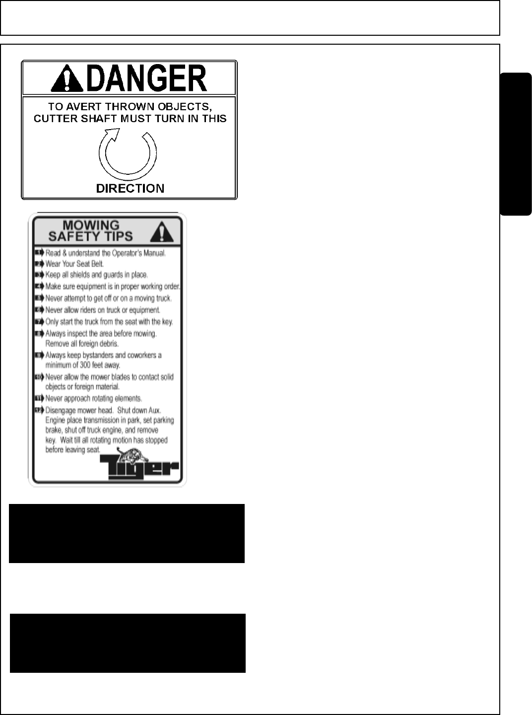
6 42350 1 DANGER Cuttershaft Direction
7 33743 1 INSTRUCT Mowing Safet Tips
8 42399 1 REFLECT Red Reflector
9 42400 1 REFLECT Amber Reflector
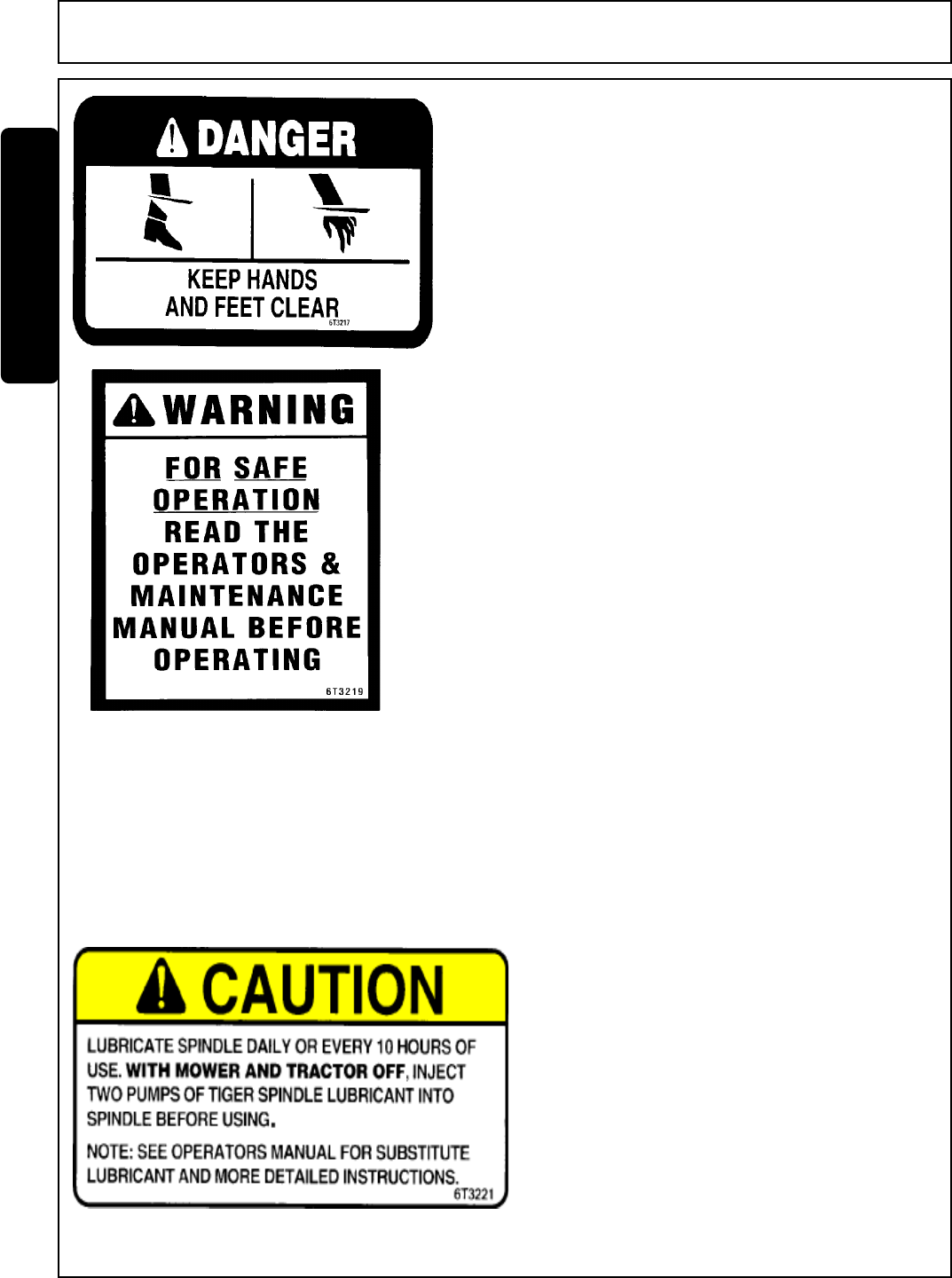
10 6T3217 1 DANGER Keep Hands and Feet Clear
11 6T3219 1 WARNING Read Operators and Maintenance Manuals
12 6T3220 1 INTRUCT Lubricate Pump, Driveshaft Daily
13 6T3221 1 CAUTION Lubricate Spindle When Mower and Tractor Off
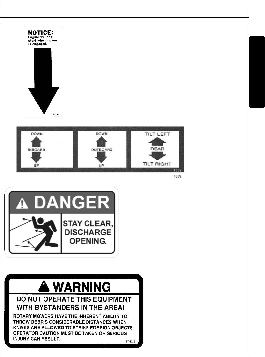
14 6T3222 1 INSTRUCT Engine will not start when mower is engaged
15 1059 1 INSTRUCT Mower Positions
16 6T3224 1 DANGER Stay Clear, Discharge Opening
17 6T3230 1 WARNING Don't Operate with Bystanders in Area
18 6T3233 1 CAUTION DONOT Start or Run with Valves closed
19 6T3234 1 CAUTION Check Crankshaft Adapter Daily
20 6T3236 1 LOGO Made In USA
21 6T3243 1 WARNING Replace Bolts and Locknut if damaged
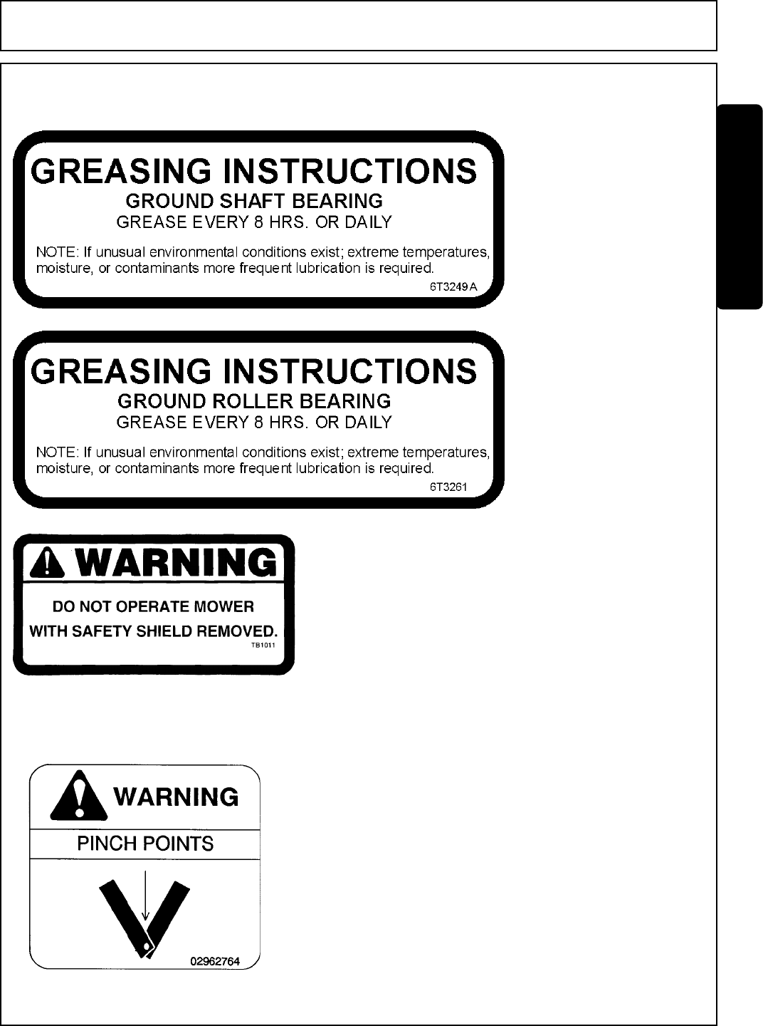
22 6T3249A 1 INSTRUCT Grease Inst. Cuttershaft Bearing
23 6T3261 1 INSTRUCT Grease Inst. Ground Roller Bearing
24 TB1011 1 WARNING Do Not Work Mower with Safety Shiel Removed
25 02962764 1 WARNING Pinch Point
26 02965262 1 WARNING Hydraulic Hose Repair
27 02967827 1 DANGER Multi Warn Messages
28 34852 1 INSTRUCT Hydraulic Specifications
29 00756059 1 WARNING Check Hydraulic Hose with Cardboard

Side Rtry Safety Section 1-14
SAFETY
SAFETY
10"X5.5" 31522
MOWER DECK
18.25"X10" 31523
HYDRAULIC TANK
22840
INSIDE OF CAB
22839
MOWER DECK
PART NO.
LOCATION
24028
MOWER DECK
Side Rtry Safety Section 1-15
SAFETY
SAFETY
5
42399
MOWER DECK
42400
MOWER DECK
33743
INSIDE OF CAB
42350
MOWER DECK
PART NO.
LOCATION
Side Rtry Safety Section 1-16
SAFETY
SAFETY
29-6T3221
6T3220
FRONT PUMP MOUNT
6T3221
INSIDE OF CAB
6T3219
INSIDE OF CAB
6T3217
MOWER DECK
PART NO.
LOCATION
Side Rtry Safety Section 1-17
SAFETY
SAFETY
6T3236
MOWER DECK
6T3243
INSIDE OF CAB
6T3234
INSIDE OF CAB
6T3233
INSIDE OF CAB
PART NO.
LOCATION

Side Rtry Safety Section 1-18
SAFETY
SAFETY
16
6T3236
MOWER DECK
HYDRAULIC TANK
6T3243
INSIDE OF CAB
6T3234
INSIDE OF CAB
6T3233
HYDRAULIC TANK
PART NO.
LOCATION
Side Rtry Safety Section 1-19
SAFETY
SAFETY
TB1011
MOWER DECK
02962764
MOWER DECK
DRAFT BEAM
6T3261
MOWER DECK
6T3249A
MOWER DECK
PART NO.
LOCATION

Side Rtry Safety Section 1-20
SAFETY
SAFETY
02967827
CAB FENDER
02965262
DRAFT BEAM
PART NO.
LOCATION

Side Rtry Safety Section 1-21
SAFETY
SAFETY
00756059
MOWER DECK
34852
HYDRAULIC TANK
Side Rtry Safety Section 1-22
SAFETY
SAFETY
ITEM PART NO. QTY. DESCRIPTION
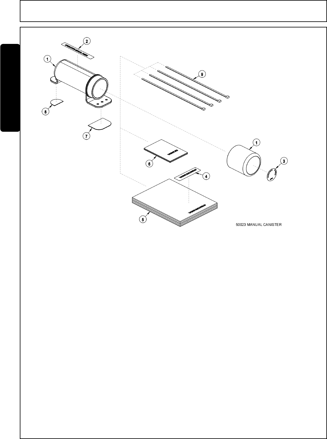
50023 AVAIL MANUAL CANISTER COMPLETE
1 00776031 1 Round Manual Canister
33997 1 Decal, Sheet, Manual Canister
2 * Decal
3 * Decal
4 * Decal
5 * AVAIL Specification Product Manual
6 33753 1 EMI Safety Manual
7 34296 1 Front Adhesive Pad
8 34297 1 Rear Adhesive Pad
9 6T1823 4 Zip Tie 14" Long
NOTE:
The manual canister can be bolted, zip tied or adhered to a variety of surfaces. Locate a protected area within
the view of the operator. Then select an installation method and attach the canister. CAUTION-AVOID DRILL-
ING HOLES INTO UNKNOWN AREAS, wires and other parts may be located behind these areas. When
adhering the canister to a surface, thoroughly clean that surface before installing the canister.

Side Rtry Safety Section 1-23
SAFETY
SAFETY
This section is intended to explain in broad terms the concept and effect of federal laws and regulations concerning
employer and employee equipment operators. This section is not intended as a legal interpretation of the law and
should not be considered as such.
Employer-Employee Operator Regulations
U.S. Public Law 91-596 (The Williams-Steiger Occupational and Health Act of 1970) OSHA
This Act Seeks:
“...to assure so far as possible every working man and woman in the nation safe and healthful
working conditions and to preserve our human resources...”
DUTIES
Sec. 5 (a) Each employer-
(1) shall furnish to each of his employees employment and a place of employment which are free
from recognized hazards that are causing or are likely to cause death or serious physical harm to
his employees;
(2) shall comply with occupational safety and health standards promulgated under this Act.
(b) Each employee shall comply with occupational safety and health standards and all rules,
regulations and orders issued pursuant to this Act which are applicable to his own actions and
conduct.
OSHA Regulations
OSHA regulations state in part: “At the time of initial assignment and at least annually thereafter,
the employer shall instruct every employee in the safe operation and servicing of all equipment with
which the employee is, or will be involved.”
Employer Responsibilities:
To ensure employee safety during Truck and Implement operation, it is the employer’s responsibility to:
1. Train the employee in the proper and safe operation of the Truck and Implement.
2. Require that the employee read and fully understand the Truck and Implement Operator’s manual.
3. Permit only qualified and properly trained employees to operate the Truck and Implement.
4. Maintain the Truck and Implement in a safe operational condition and maintain all shields and guards on the
equipment.
5. Ensure the Truck is equipped with functional seat belts and require that the employee operator securely
fasten the safety belts at all times.
6. Forbid the employee operator to carry additional riders on the Truck.
7. Provide the required tools to maintain the Truck and Implement in a good safe working condition and provide
the necessary support devices to secure the equipment safely while performing repairs and service.
Child Labor Under 16 Years of Age
Some regulations specify that no one under the age of 16 may operate power machinery. It is your responsibility
to know what these regulations are in your own area or situation. (Refer to U.S. Dept. of Labor, Employment
Standard Administration, Wage & Home Division, Child Labor Bulletin #102.)
FEDERAL LAWS AND REGULATIONS

Side Rtry Safety Section 1-24
SAFETY
SAFETY

ASSEMBLY
SECTION
Assembly Section 2-1

Assembly Section 2-2
ASSEMBLY
CRANKSHAFT ADAPTER
If necessary remove the four capscrews from the crankshaft pulley. Then install
the crankshaft adapter plate and adapter to the pulley with capscrews and lockwashers
as shown in the parts section.
Before attempting to mount your Tiger mower, it is
important to read an understand all of the Safety Messages
in the Safety section of this manual.
Check complete shipment list against the packing list to make sure there are no
shortages. Make certain the tractor model is the appropriate one for the mower received!
Always use a floor jack, hoist or fork lift to lift and raise heavy parts.
Read and understand the entire assembly section instructions before attempting to
mount your Tiger mower. Refer to the parts section of this manual for detailed illustrations
to locate all parts.
TRACTOR PREPARATION
A: Remove right hand steps.
B: Disconnect battery cables from both batteries.
C: Remove engine side panels, or raise hood to access front pulley.
D: Remove plugs from tractor casting where main frame and pump
mount will be attached.
E: Remove any front weights and weight supports.
F: Raise the tractor onto jack-stands and remove the rear wheels.
ADJUSTING REAR WHEELS
Follow the instructions in the tractor owners manual for adjusting tires and
rims. The rear wheels MUST be adjusted to the widest setting. NOTE: This may
require switching the wheels to opposite sides of the tractor. Also take note of any width
restrictions when transporting by trailer. (For ease of installation, it is best to leave rear
wheels removed during installation of the mower).

Assembly Section 2-3
ASSEMBLY
AXLE BRACE INSTALLATION
With the tractor on jack-stands, remove the existing hardware and the three point
links on the rear axle where the axle braces will be mounted. Use a hoist to raise the
axle braces to the correctly matching mounting holes on the rear axle and the main
frame. Use the existing hardware to attach the braces to the tractor. NOTE: All
capscrews are threaded from the bottom up, except the inner rear capscrew. DO
NOT tighten the hardware at this time. Remove the capscrews one at a time and
apply a thread locking agent. Reinsert the capscrews and tighten / torque to values
noted in the torque chart located in the maintenance section of this manual.
Reattach the links to the three point hitch with the existing pins.
MAIN FRAME INSTALLATION
With an overhead hoist and / or jack-stands, raise one side of the frame up to the
correctly matching mounting holes. Install capscrews and all other hardware as shown
in main frame parts section to secure the sides of the main frame to the tractor casting,
DO NOT tighten at this time. Remove the capscrews one at a time and apply a thread
locking agent. Reinsert the capscrews and tighten / torque to values noted in the torque
chart located in the maintenance section of this manual. ( The front capscrews are
14mm X 1.5 pitch, Class 10.9. They should be torqued to 155 Ft.-Lbs. - Dry or
122 Ft.-Lbs. - Lubricated.)
KUBOTA RIGHT SIDE FUEL TANK
NOTE: THE FUEL TANK IS REPLACED ONLY ON BOOM UNITS.
Drain the right hand fuel tank. Remove the three hoses and the wire connection to
the fuel gauge. Remove and reuse the fuel gauge, the gasket and hardware. The
gasket has a unique hole pattern and is marked to match the fuel gauge. When taking
out the gauge, pull upward until the float reaches the top of the tank. Tip the gauge
toward the opposite end of the tank and remove the gauge. Save the gauge for later.
Remove the tank straps and the lower cross bar and discard. Drill two 1/2” holes
on the upper front plate according to the measurements shown in the parts section.
Drill two 1/2” holes on the lower rear plate according to the measurements in the parts
section.
To add the tank gauge to the Tiger tank, first place the gasket that you removed from
the original tank on the fuel gauge and match up the holes. Insert the float section of the
gauge into the top hole. Then tip the gauge so the long end of the gauge fits into the
long end of the tank. Secure the gauge with the existing hardware.
Add the barbed elbow to the top of the tank. Place the rear tank strap over the back
end of the tank. Insert the front tank strap into the holes on the top plate and hold in
place with the Tiger hardware. Insert the back end of the fuel tank on to the rear plate.
Slide the front end of the tank into the front tank straps. Place one piece of split hose on
the lower rear plate under the Tiger tank. Thread the Tank strap into the newly drilled
holes and add he hardware. Cut the other piece of split hose in half and add them to the
front tank strap corners under the tank. This keeps the straps from wearing holes in
the tank. Tighten the hardware and secure the fuel tank to the tractor.
Finally, attach the proper hoses to the corresponding holes and add the wires for the
fuel gauge. Refer to the parts section for hardware used and dimensions.

Assembly Section 2-4
ASSEMBLY
BUMPER HYDRAULIC TANK INSTALLATION
Install all fittings and tubes into tank and tank filter as shown in the parts section
illustration. Insert tank sight glass on the inner right side of the tank. Install the
temperature sensor (optional), or pipe plug into side of the tank.
Attach the large mounting brackets on the front casting of the tractor. Secure the
brackets to the tank with the hardware shown in the parts section.
Install the filter gauge into the filter housing so that it points to the rear of the tractor
and is clearly visible to the operator. The breather cap will be installed after tank is
filled.
FRONT PUMP MOUNTING
Install the pump mounting bracket on the front of the tractor with capscrews and
lockwashers as shown in the parts section illustration. DO NOT tighten fasteners at
this time.
Slide the pump drive shaft into the crankshaft adapter. The end with the shorter
splines should be inserted into the adapter (if applicable).
Slide the splined drive shaft coupler onto the pump drive shaft. Install the pump on
the mounting bracket. NOTE: the shaft is offset to one direction, the pump should be
installed with the offset side on top. Install hardware for securing pump to the pump
mount, DO NOT tighten.
Align pump so that splined coupling can be moved back and forth by hand. Tighten
pump mounting bolts in succession rechecking for spline coupling movement. Remove
the pump mounting bracket bolts one at a time and apply a thread locking agent. Tighten
these bolts in succession, again checking for free movement in the drive shaft. After all
bolts are torqued, the end play on the drive shaft should be 1/16” to 1/8”, and coupler
should move freely with hand pressure. If end play is less than 1/16”, grind the end of
the shaft to achieve the proper end play. If there is more than 1/4” of end play, return the
shaft with specifications for a longer shaft.
CAUTION: DO NOT START THE TRACTOR UNTIL ALL HOSES ARE
ATTACHED AND TANK IS FILLED WITH PROPER OIL! STARTING THE TRACTOR
AT THIS TIME WILL CAUSE SERIOUS DAMAGE TO THE PUMP.
TEMPERATURE GAUGE MOUNTING
(OPTIONAL)
Mount the temperature gauge where it is clearly visible to the operator. Attach the
green (-) wire from the negative post on the gauge to a grounded bolt on the tractor
frame. Remove paint if needed to make a good ground. Remove the pipe plug from the
side of the hydraulic reservoir, and install the temperature sensor using thread sealing
tape. Run the white wire from the (s) sensor post of the gauge to the temperature
sensor on the hydraulic reservoir tank.
Assembly Section 2-5
ASSEMBLY
FILLING HYDRAULIC RESERVOIR
Refer to the maintenance section for filling specifications and hydraulic oil
requirements.
NOTE: Starting or running your Tiger mower before filling reservoir will
cause serious damage to hydraulic pump.

Assembly Section 2-6
ASSEMBLY
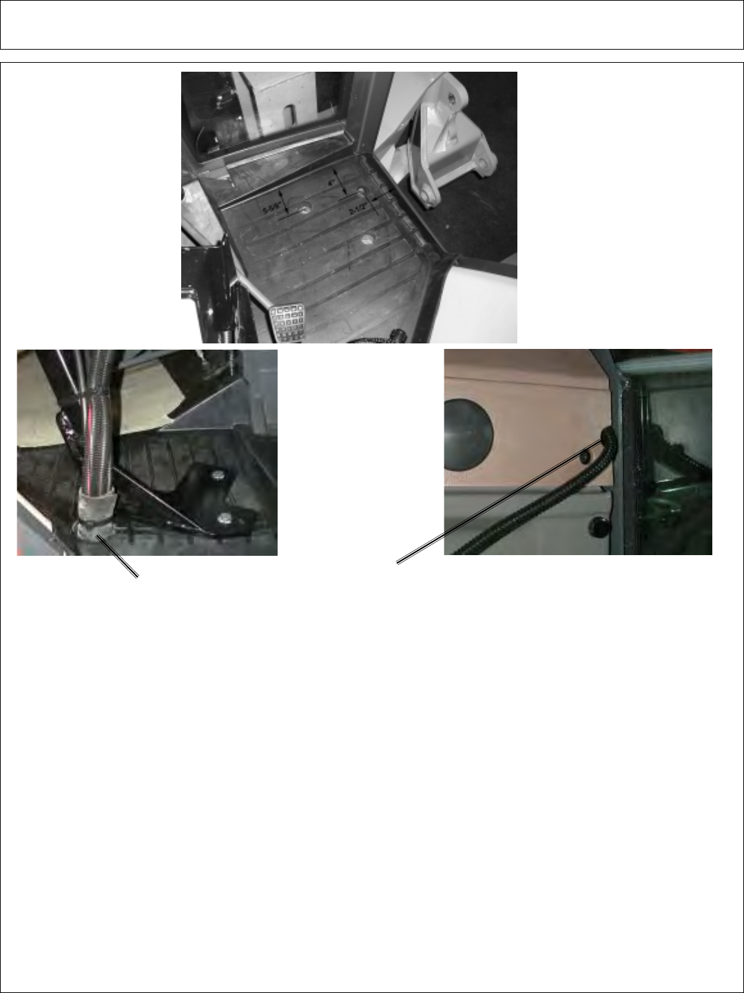
CABLE CONTROL MOUNTING BRACKET
Preassemble the cable control boxes to the control mounting bracket as shown in
the parts section. Use the image below for positioning the cable control
bracket. Position the support bracket on the floor as a template. The upper right
hole of the bracket is 2-1/2” from the right edge of the floor mat and 4” from the upper
lip of the mat as shown below. The upper left hole of the bracket is 5-5/8” from the
upper lip of the mat as shown below. Mark the holes on top of the floor mat. Be sure
that the location of the stand will allow clearance between the cable control box
handles and all existing interior levers, etc. Also watch out for wiring and brackets
when placing the bracket for drilling and cutting. Cut holes in the mat with a 1” hole
saw. The spacers provided are used to allow the cable control bracket to set on top
of the floor mat while being held securely to the floor of the cab. Drill 3 holes for the
capscrews using the bracket and spacers as a template. Then secure with the
hardware as noted in the parts section.
VALVE MOUNTING BRACKET
The valve mounts are made to fasten to the back fenders of the tractor. The top
rear hole on the mounting bracket match an existing hole on the fender. Ream out
the existing mounting holes to fit the 3/8” hardware. Attach the valve mounting plate
to the brackets. Next, attach the brackets to the fender by the rear holes, level the
valve mounting plate and mark the two remaining holes on each bracket. Drill the
four remaining 3/8” holes. Apply the hardware to the top two holes of the valve
mounting brackets and attach them to the fender.
The ends of the valve mount brace are threaded and the brace supports the lower
portion of the bracket. Refer to the parts section for the hardware used. Attach the
right lower hole of the bracket to the fender with the 3/8” capscrew, flatwasher and
hex nut. Thread the brace on to the end of the lower right capscrew. Attach the
other end of the brace to the fender and to the bracket with the other capscrew and
flatwasher.
EXISTING
HOLE
VALVE MOUNT
BRACE
HEX NUT
FENDER
RIGHT VALVE
MOUNTING
BRACKET
LEFT VALVE
MOUNTING
BRACKET
Assembly Section 2-7
ASSEMBLY
FRONT STEERING CONSOLE - CUT HOLE TO ACCESS
POWER SOURCE FOR SWITCH BOX
CABLE SWITCH BOX WIRING
Refer to the parts section for wiring diagram to hook up the switch box. Cover the
four wires from the switch box with plastic wire wrap provided. Route the wires, that
tap into the tractors power, from the switch box to the front council panel. Remove the
console panel under the steering wheel to access wires. Locate the black wire with
the white stripe. Using a test light or meter verify this wire is the neutral safety wire.
Cut the black wire with the white stripe and connect the green wires from the switch
box as shown in the wiring diagram. The red wire is to be hooked to the tractor ignition
switch or an available slot in the fuse box. NOTE: Be certain that the power taken
for the switch box is “HOT” ONLY when the tractor ignition is “ON”. Also
double check that the line is fused.
Cut a 2-1/8” hole through the floor mat and cab floor at the base of the right console
and the cable mounting bracket. Check under the cab and under the mat for a clean
cut. Run the switch box wires out with the cables and wrap with hose wrap. Secure
the hose wrap with zip ties. Place trim lock around the hole. Run the cables to the
valve. Run the white wire to the solenoid valve. Cover wires with wire wrap.
The wires from the switch box are longer than needed and should carefully cut and
spliced as required. Zip ties should be used to secure the wires and cables to the
tractor framework.
2 1/8” HOLE
Assembly Section 2-8
ASSEMBLY
HUSCO VALVE MOUNTING
Match the holes on the valve to the holes on the valve plate. The holes on the
plate for the cables should be on your right. Always start by matching the mounting
holes on the Husco valve to the two mounting holes closest to you on the plate.
There will be two more holes on the plate to match the other mounting holes on the
valve. Use the hardware shown in the parts section to mount the valve to the valve
plate. Refer to the parts section for all parts and hardware needed.
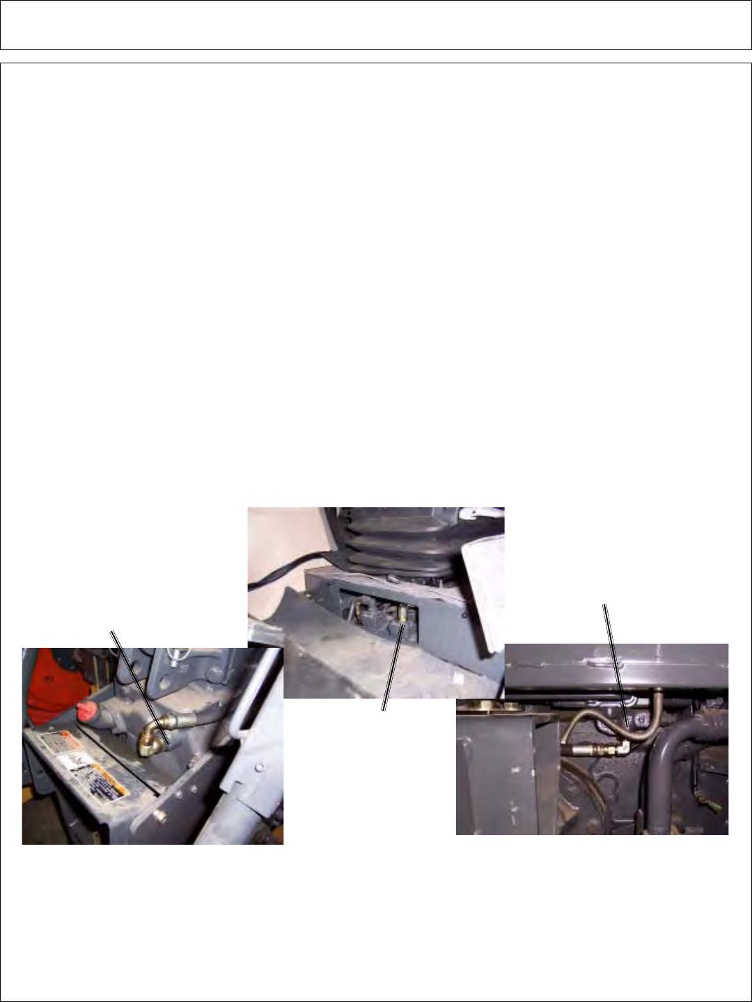
HUSCO HYDRAULIC LINE INSTALLATION
The Tiger Husco valve used needs to access the pressure, return and power
beyond ports of the tractor. To access the ports, 1/2” adapters are used.
The pressure port is located under the drivers seat in the cab. Route the hose
from the pressure port to the high pressure filter. Next run the pressure hose from
the filter to the pressure port on the Husco valve.
The return port is located above the PTO shaft and to the right of the oil filler cap.
The return hose runs from the return port on the Husco valve to the return port on the
tractor.
The power beyond port is located by the right rear axle of the tractor. Install the
hose from the power beyond port of the Husco valve to the power beyond port of the
tractor.
RETURN PORT
PRESSURE PORT
POWER BEYOND
PORT
HIGH PRESSURE FILTER - HUSCO
The high pressure filter is mounted to the right valve mounting bracket with two
capscrews, as shown in the parts section. Attach the two adapters to the filter. The
pressure line from the tractor is plumbed to the left side of the filter. The pressure
hose that is attached to the right side of the filter feeds the pressure port of the Tiger
lift valve.

Assembly Section 2-9
ASSEMBLY
POLYCARBONATE SAFETY WINDOWS
NOTE: Installing a boom mower requires that all of the right side windows be
replaced with polycarbonate. Install the safety windows after all of the cab wiring and
mounting is done; and before the boom arm is mounted. Locate all the hardware in the
Parts Section on the Safety Screen page, when installing the polycarbonate.
Remove the right hand rail, the right rear window and the right door from the tractor
cab. Remove the hardware and check the parts section for which parts are re-used.
Wrap the trim seal around the polycarbonate and cut the trim to match the other end so a
seal will form to the frame. Apply the adhesive in the groove of the trim seal where the
polycarbonate sits and apply the trim seal to the polycarbonate. Add the hardware for
the existing holes to the polycarbonate and install the polycarbonate to the tractor frame.
Locate the 4 holes where the hand rail attaches to the cab. Place the front two
support brackets over the holes and attach the hand rail over the brackets with the
hardware provided. Place the bottom support bracket in the center of the bottom edge of
the door and mark the position of hte center hole. Drill one 3/8” hole through the door
frame. Use the hardware shown in the parts book to secure the bracket into place.
Locate the existing harware over the fender in the door frame of the cab. Position
the polycarbonate mount over the coresponding holes. Remove the existing hardware.
Attach the mount to the fender with the hardware provided. Drill a 5/16” hole through the
polycarbonate and secure the window to the mount.
BRACKETS
POLYCARBONATE
MOUNT
EXISTING
HARDWARE
Assembly Section 2-10
ASSEMBLY
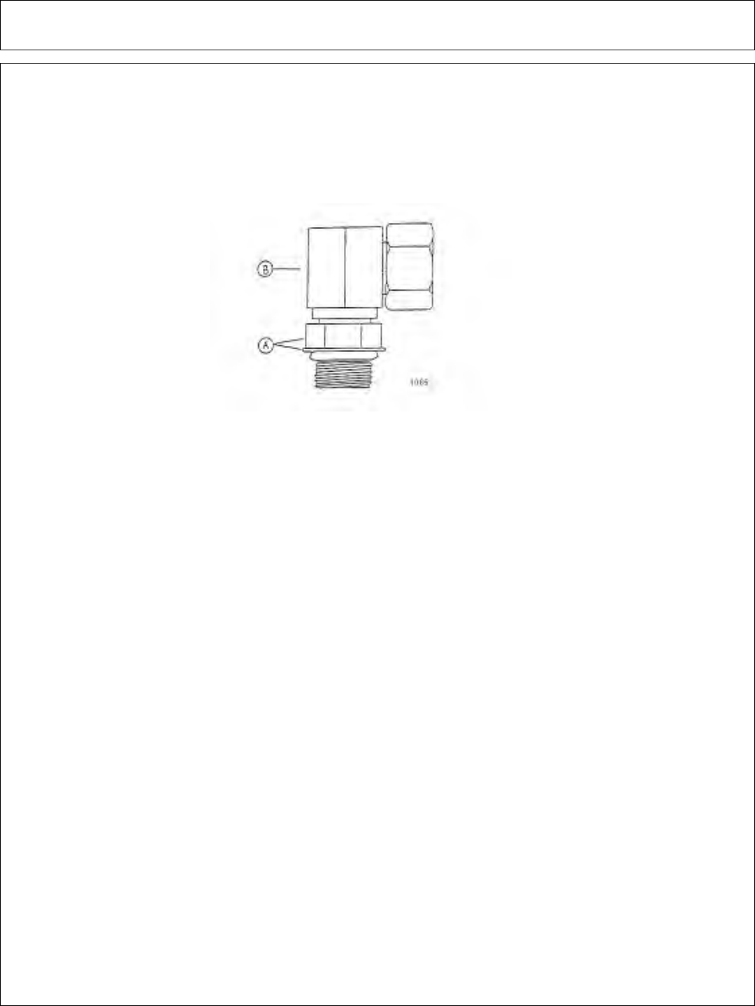
INSTALLING O-RING FITTINGS
Installing straight, 45° and 90° O-rings requires that the O-ring and washer (A) be up
against the swivel body (B). Insert the swivel and turn in until the swivel is pointed in the
right direction and the O-ring contact is made. Hold swivel in set direction with a wrench
and turn the O-ring contact is made. Hold swivel in set direction with a wrench and turn
the O-ring nut away from the swivel body and carefully tighten.
INSTALLING NATIONAL PIPE FITTINGS
Whenever installing a pipe fitting, wrap the thread clockwise (looking at the end)
with teflon tape. In this way, the tape will be tightened when installed. NOTE: It is not
necessary to tape O-ring fittings, or those installed in swivels.
GENERAL HOSE INSTALLATION
Refer to the parts section for detailed information about hoses and fittings for this
application.
Whenever mounting the suction hose between the pump and the tank, the stainless
steel bands provided must be used. CAUTION: DO NOT use regular hose clamps for
this purpose.
HOSE COVERING
Where hoses may contact the frame or other edges, wrap with split hose and
secure with hose clamps or zip ties. On non cab units the pressure and return
hoses from the control valve will also need to be routed inside the protective clear
hose wrap. Cover the valve, valve fittings with the yellow hose cover and secure with
black string provided.
Assembly Section 2-11
ASSEMBLY
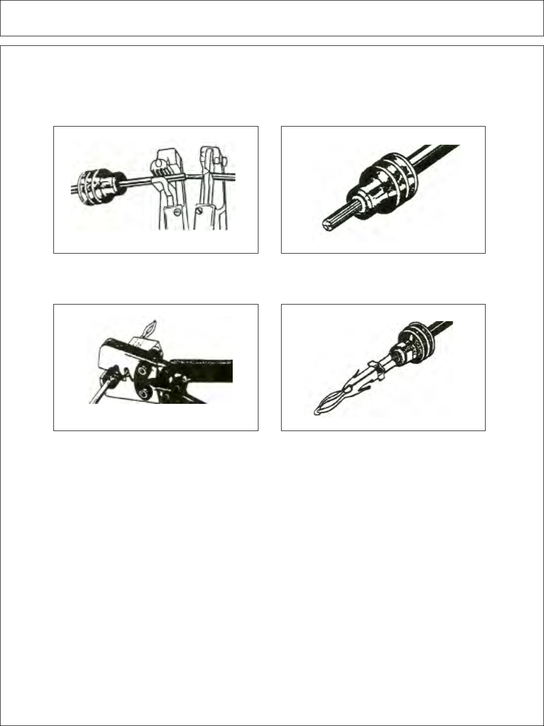
WEATHER-PACK/METRI-PACK ASSEMBLY
These instructions apply to both Weather-Pack and Metri-pack connectors.
NOTE: Use the specific tool for the type of connector you are assembling.
1. Apply seal to cable, before stripping 2. Align seal with cable insulation.
3. Put terminal in crimping tool, then 4. Crimp and visually inspect for a good
Assembly Section 2-12
ASSEMBLY
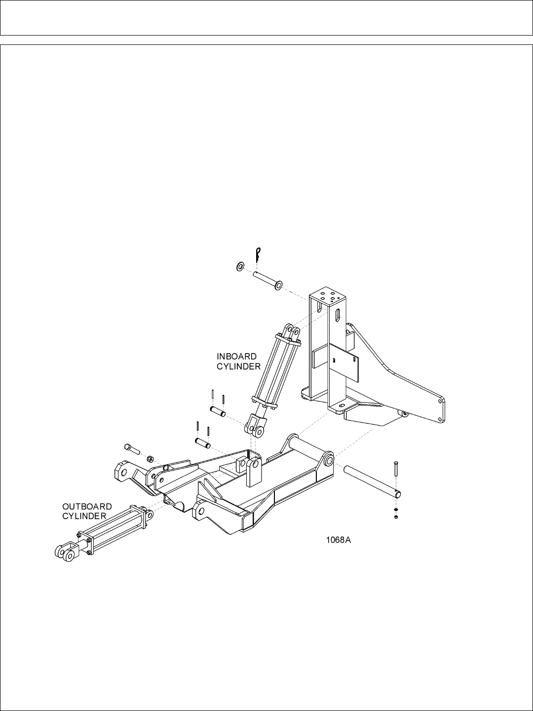
DRAFT BEAM MOUNTING
Pull the inboard cylinder piston rod down to the extreme extended position. Slide
the draft beam under the cylinder, and align clevis hole with draft beam hole nearest
to the tractor. Install pin and secure with rollpin.
Using inboard cylinder as a pivot point, slide draft beam under tractor and install
draft beam pin. Align hole in draft beam pin with holes in main frame boss and install
cap-screw, lock-washer and hex nut.
COMBO LIFT DRAFT BEAM INSTALLATION
Install ½” O-ring breather into butt port of inboard cylinder. Install fittings in the
rod end of the cylinder according to the diagram in the commons section. These
fittings should be positioned to face the butt end of the cylinder.
Next turn the clevis onto the rod of the cylinder until it is tight against the shoulder
and lock into place with locking bolt on clevis.
The inboard cylinder can now be installed into the main frame mast with the pin,
flat-washers and R-clips as shown below. Use teflon tape on all fitting and hose
connections.
Install all fittings in the outboard cylinder and adjust to point towards the butt end
of the cylinder. Attach the hoses as specified in the parts book. Slide the cylinder
into the draft beam from the outside of the draft beam and attach cylinder to the draft
beam with clevis pin and rollpins.
Assembly Section 2-13
ASSEMBLY
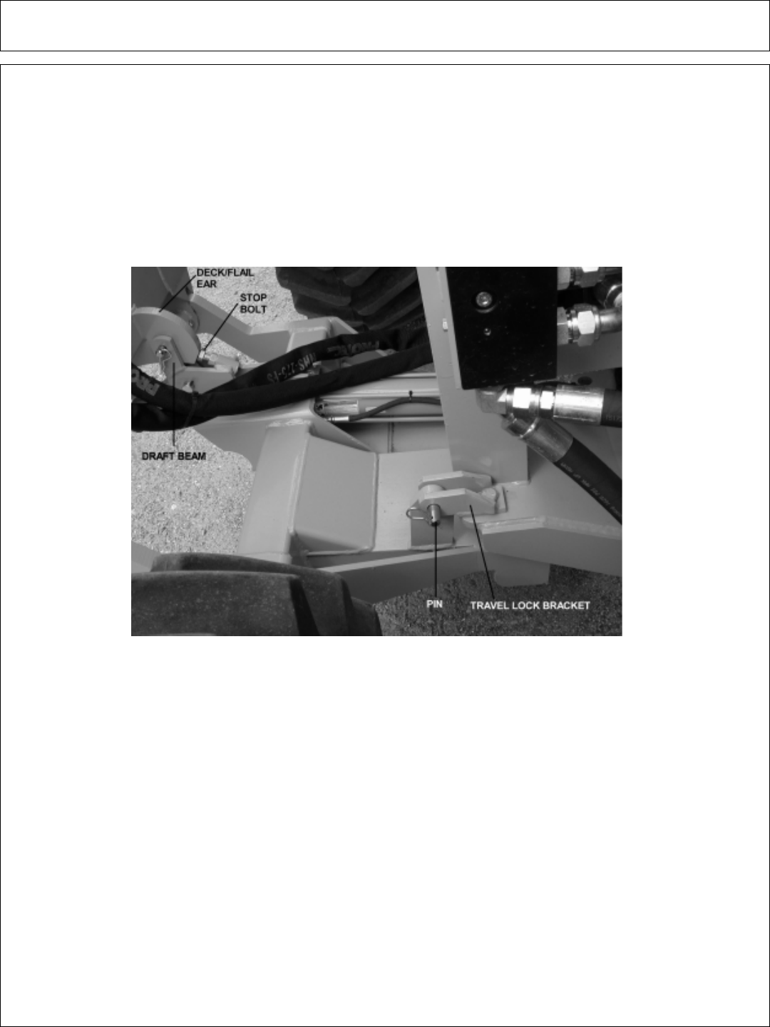
TRAVEL LOCK MOUNTING
Install the travel lock bracket with pin and clip on the draft beam. Slide the draft
beam and align the travel lock bracket hole with the mounting hole on the main frame.
Install the capscrew, lockwasher and hex nut as shown in the picture.
Raise the deck/flail to it’s upright position (Deck ear touches to stop bolt as
shown in the picture). Drill a 13/16” hole to the deck/flail ear through the draft beam
as shown below. Insert the supplied pin and clip through the hole.
STOP BOLT ADJUSTMENT
The stop bolt is not required on flail side mowers and should not be installed on
the combo draft beam.
NOTE: When the outboard cylinder is fully extended, the bonnet should be up
against the stop or if travel locks are installed, it should be up against the travel lock.
It may be necessary to use either external or internal slugs on the cylinder to get the
correct stroke. If the cutter head is against the stop and the cylinder has stoke
remaining, serious damage will occur.
Proceed to final preparation for operation instructions on the next page.
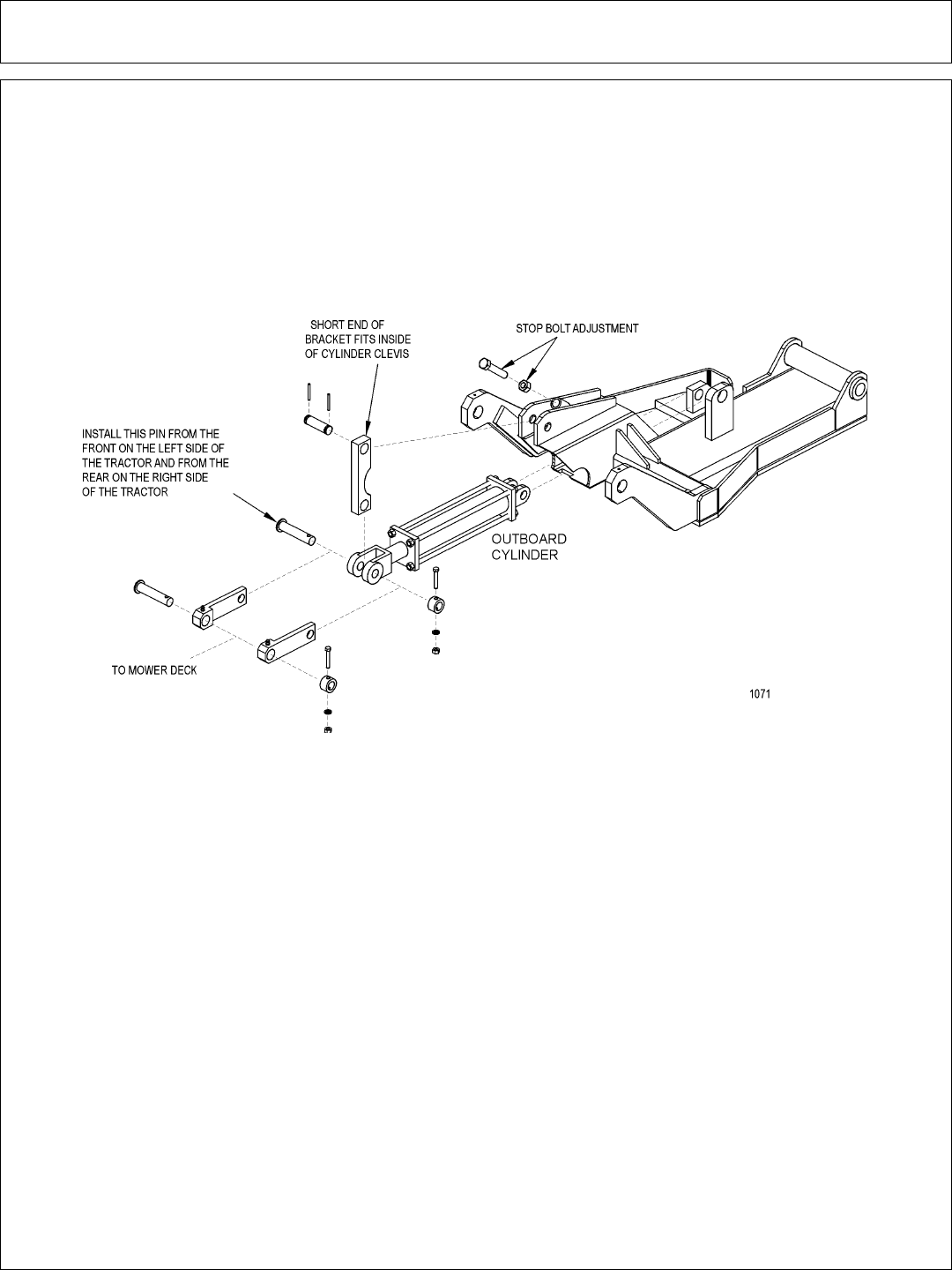
Assembly Section 2-14
ASSEMBLY
Slide other end of pivot arm with short distance between the cut-out and the end
of the pivot arm, into the cylinder clevis. Next, line up the holes of the left and right lift
linkage arms outside of the cylinder clevis holes. Connect with linkage pin, shims
(as required), boss, cap-screw, lock-washer and hex nut as shown.
To connect the bonnet to the draft beam, slide the extension arms of the draft
beam between the mounting ears on the inner end of the bonnet. Line up the holes
and secure with swivel pin, cap-screw, lock-washer, and hex nut (both sides). See
parts book illustration.
Next, slide the left and right linkage arms up to the slotted ear on the side of the
deck. Secure with linkage pin, shims, boss, cap-screw, lock-washer and hex nut.
See illustration in parts section.
DECK MOUNTING
Check that all grease zerks have been installed in the draft beams pivot arm, left
linkage arm, right linkage arm, and cylinder mounting ears.
Using a clevis pin and roll pins, connect the pivot arm to clevis on draft beam.
NOTE: Make sure the longer distance between the cutout and the end of the pivot
arm is closest to the draft beam pivot ears on the center tube as shown in the
diagram below. Also make sure the cutout on the pivot arm faces into tube of draft
beam.
LIFT CONTROL FEEDLINES
Hose lengths will vary between tractor applications such as cab and non-cab
units. See the parts section that pertains to your tractor for hose applications.
Install a hose from the bottom or inner valve port (in fender well for cab units, on
stand for non-cab units) to the restrictor on the inboard cylinder gland.
Install a hose form the upper or outer valve port to the restrictor on the outboard
cylinder butt. Use teflon tape on all fitting and hose connections.

Assembly Section 2-15
ASSEMBLY
DECK / MOTOR FEEDLINE
Install the 1” hose with the 90 degree flange on the front side of the motor to the
inside upper oil port of the solenoid valve. Secure to motor with flange kit, and install
swivel fittings on the other end. Install the other 1” hose with the 60 degree flange on
the back side of the motor to the inside lower oil port of the solenoid valve.
Install split hoses around hydraulic hoses where they contact sharp edges, or any
other edges that may rub hoses.
Be sure that all grease zerks are installed in the draft beam pin bosses. Grease
all areas of the draft beam according to the instructions in the maintenance section.
Re-check all fittings for tightness and be sure teflon tape has been used at all
connections.
Fill hydraulic tank with fluid as recommended in the maintenance section. BE SURE
TO OPEN THE BALL VALVES. Start the tractor and operate the inboard cylinder
through the entire stroke and the outboard cylinder through the bottom ¾ stroke
repeatedly to clear the lines of air. DO NOT run outboard cylinder out to full
stroke until stop bolt has been adjusted!
Check for oil leaks at all fittings and connections using a piece of paper or cardboard.
If a leak is found, you must shut down the tractor and set the cutter head on the
ground. Before attempting to fix the leak, you must actuate the lift valve handles
several times to relieve any pressure in the lines. DO NOT USE HANDS TO
CHECK FOR FLUID LEAKS!
Raise the three point hitch and check the tractor internal hydraulics, fill to proper
level if needed.

Assembly Section 2-16
ASSEMBLY
FINAL PREPARATION FOR OPERATION
Place operators safety and operation decals on the steering column and side
counsel where they are clearly visible to the operator. These decals should be
understood by each operator of the machine in conjunction with the safety and
operation section of this book. The decals are to remain in good condition as a
reminder to the operator, and should be replaced if damaged.
Double check that all pivot points have been greased. Secure all hoses together with
zip ties and wrap with split hose sections where friction may occur on the hose.
BEFORE starting or operating the tractor you must read and
understand the safety and operation sections of this manual
completely.
Before operating the mower, the cutter head and draft beam should be slowly
moved throughout the full range of motion. Watch for any condition that would cause
pinching or excess stress on the hoses. The steering and front axle travel should
also be carefully moved through their full range of motion. If any condition occurs in
which the hoses contact the tires, the steering and / or front axle travel may need to
be limited as described in the tractor operators manual. This should also be done if
the tires rub, or are extremely close to any other part of the mower such as the
hydraulic tank or draft beam. This may include adding shims, or adjusting stop bolts
in the tractor front to solve the problem. While checking motion, you should also
check that the control circuits are connected according to the operators decal for the
valve handles.
MOWER TESTING
Take the tractor to a place free of loose objects on the ground. Operate the
cylinders through their full range of motion again, to clear the lines of air. Follow the
instructions in the operation section to operate the mower. Vibration of the mower
should be minimal at all times. After a 5 minute test run, the knife bolts should be
retorqued and once again after the first few hours of operation.
If any parts of this assembly section, or any other section of this
manual are not clearly understood you must contact your dealer or the
address on the front of this manual for assistance!

OPERATION
SECTION
Operation Section 3-1

Side Rtry Operation Section 3-2
OPERATION
Safety is of primary importance to the owner / operator and to the manufacturer.
The first section of this manual includes a list of Safety Messages, that, if followed,
will help protect the operator and bystanders from injury or death. Many of the
messages will be repeated throughout the manual. The owner / operator / dealer
should know these Safety Messages before assembly and be aware of the hazards
of operating this mower during assembly, use, and maintenance.
The Safety Alert Symbol combined with a signal word, as seen below, is
intended to warn the owner / operator of impending hazards and the degree of injury
possible during operation.
Indicates an imminently hazardous situation that, if not avoided, WILL result in DEATH
OR VERY SERIOUS INJURY.
Indicates an imminently hazardous situation that, if not avoided, COULD result in
DEATH OR SERIOUS INJURY.
Indicates an imminently hazardous situation that, if not avoided, MAY result in MINOR
INJURY.
Identifies special instructions or procedures that, if not strictly observed, could result
in damage to, or destruction of the machine, attachments or the enviroment.
NOTE: Identifies points of particular interest for more efficient or convienient operation or
repair. (SG-1)
Before any operation of tractor and mower, the user should read and
understand the safety and operating instructions for both the tractor and
the mower. The user should also be familiar with the location and
functions of the units instruments and controls. Being familiar with the
machine and it’s controls will increase efficiency and reduce possibility of
serious injury or damage to the unit. The operator should work slowly and carefully
until he feels comfortable with the machine. Speed and skill will be attained much
easier if the necessary time is spent to familiarize yourself with the machine and its
operations.
Since tractor makes and models vary, we recommend reading and following the
operators manual provided by the manufacturer pertaining to your particular unit.
IMPORTANT!

Side Rtry Operation Section 3-3
OPERATION
STARTING TRACTOR AND MOWER
Check the operators manual received from the tractor manufacturer, for
their recommendation and procedures pertaining to your particular make and model.
When rotating parts are in motion, serious injury may occur if caution is
not used or danger is not recognized. Never allow bystanders within 300
feet of the machine when mower is in operation.
Be sure the ball valves on the mower hydraulic tank are OPEN before
starting the tractor. Serious damage to the hydraulic system can occur if
the valves are not open.
Check to make sure mower switch is in the “OFF” position. The unit is
designed not to start if the switch is in the “on” position. If tractor starts
with switch on, turn off tractor and contact your local Tiger dealership for
assistance.
Start the tractor and allow the instruments to stabilize. Without starting the
mower, practice positioning the boom and deck. Remember, speed and skill will be
attained easier if the necessary time is spent familiarizing yourself with the machine
and its operations. When you feel comfortable at controlling the position of the
mower, return the mower to the travel position, and transport the mower to the
desired mowing location.
If mowing for the first time with a Tiger Boom Mower, we recommend choosing a
ditch or area relatively flat with a minimum of sign posts, guard rails, etc. As always,
you should inspect the area for other objects that can cause potential hazards.
The Mower Control switch turns the mower “ON” and “OFF”. This switch is to be
in the “OFF” position to start the tractor. The tractor will not start with the switch in
the “ON” position.
If tractor starts with switch on, turn off tractor and contact
your local Tiger dealership for assistance.
CONTROL LOCATION AND FUNCTIONS
The side mower height is controlled with a two or three spool valve and is
coordinated as shown below. The optional three spool valve allows for the operation
of a rear rotary mower or side ditcher. If the unit is equipped with a three spool valve,
do not operate the third spool handle unless a rear rotary or ditcher is mounted.

Side Rtry Operation Section 3-4
OPERATION
The rear mower height is controlled with the 3-point hitch control lever. Follow the
instructions for this control is the tractor operators manual. The tilt of the rear mower is
controlled with the third spool if the lift valve and is coordinated as shown above.
The side and rear mower positions may optionally be controlled with the tractors
remote hydraulic connections or a combination of lift valve and remote hydraulics. If so,
determine which position of the side or rear mower is to be controlled be each remote
lever.
The side mower ON / OFF switch is located in a switch box mounted to the valve stand
or cable controls for non-cab and cab units respectively. If operating a rear mower, the ON
/ OFF switch is located in the switch box with a side mower switch.
This machine may be equipped with an auxiliary oil temperature gauge, an amp gauge
or oil pressure gauge. If oil temperature reaches 200 degrees Fahrenheit, stop mowers
and see trouble shooting section for possible causes. Keep an eye on all gauges for
indication of problems.
MOWER OPERATION
When rotating parts are in motion, serious injury may occur if caution is
not used or danger is not recognized. Never allow bystanders within 300
feet of the machine when in operation. Extreme care should be taken
when operating near loose objects – such as gravel, rocks and debris.
These conditions should be avoided.
The rotating parts in this machine have been designed and tested for rugged use.
However, they could fail upon impact with heavy solid objects – such as steel guard rails,
concrete abutments, etc., causing them to be thrown at a very high velocity. Never allow
cutter head to contact such objects. Inspecting the cutting area for such objects prior to
mowing can help eliminate these potential hazards.
Once on location, lower the mower deck slightly above the material to be cut, so
the mower does not have to start under a load. Bring the R.P.M. of the tractor up to 1200
and engage the side mower. If a rear mower is being used, allow the R.P.M. to return to
1200 before engaging the rear mower.
The rotary mower deck should always be carried rather than dragged on the skid
shoes when mowing on the ground. Dragging the rotary mower heads causes an
extreme side load on the tractor resulting in premature tire wear. It also causes excessive
horsepower consumption and drastically decreases blade life. Dragging the rear mower
can also cause damage to the road. Once the necessary skill is attained at controlling the
height and position of the side rotary mower, it will be easy to carry the mower head(s) and
do a proficient job of cutting.

Side Rtry Operation Section 3-5
OPERATION
When cutting tall shrubs or small trees (maximum recommended size of material
to be cut is 2” diameter) begin each pass at the top of the material and work down
with each consecutive pass. Use a low speed to allow the cutting blades time to
mulch as well as cut the foliage. When the initial pass has been made, disengage
the mower and return the mower to the travel position. Return to the starting point
and make next pass, etc.
When using the rotary cutting head for trimming trees and shrubs, let the
mower saw into them. Do not lower the mower head down directly onto a
tree or stump. The mower blades are designed to cut with the end, and
misuse can cause damage to the blade and a hazardous situation for the
operator.
To ensure a clean cut, engine speed should be maintained at approximately 1800
– 2200 R.P.M. If the tractor slows to less than 1800 R.P.M., shift to the next lower
gear. DO NOT ride the clutch, this will cause premature clutch failure. The engine
should not be operated at any time at more than 2400 R.P.M. on the tractor
tachometer.
DO NOT use excessive force when positioning cutting head into heavy
branches or small stumps (2” diameter). Damage to the unit may result.
It is best to let the cutter head “eat away” slowly at heavy cutting jobs.
The mower will operate more efficiently in tougher conditions and with less power
if the knives are kept sharp. If the mower begins to vibrate, stop the tractor, check for
wire wrapped in the spindle or damaged knives. When replacing knives, replace all
knives with new knives to ensure proper balance so the mower will not vibrate.
Severe vibration will result, if knives with unequal wear are used. Follow the
instructions in the maintenance section closely when replacing knife blades.
If bystanders approach within 300 feet while mower is in operation turn
mower switch “OFF” immediately! After shutdown, never leave the
tractor or allow bystanders to approach within 300 FEET of the unit until all
motion stops completely.
When encountering a very severe condition which causes the tractor to stall,
disengage mower, start tractor, raise the mower from the cut. Shut tractor off and
inspect the mower, blades and disk for damage before engaging mower again.
If the blades jam or stop, disengage the clutch and raise the head slightly or back
the tractor up. Normally, this will clear the cutter head. If not, shut off the mower(s),
raise the cutter heads, turn off the tractor and set the parking brake. After all motion
stops completely, leave the tractor and clear the cutting heads manually.
After the first day of operation, all bolts should be checked and tightened
securely.
This should be done periodically to ensure the bolts do not become loose and cause
damage to the tractor or mower, or injury to the operator.
Side Rtry Operation Section 3-6
OPERATION
TRANSPORTING MOWER
Transporting under the units own power:
When transporting between job sites or between cutting passes, the following
procedure should be followed: Shut off the power to the cutting head(s) and allow all
motion to come to a complete stop. Raise the draft beam to it’s highest position.
Raise the side mower until the deck stops against the draft beam. Raise the rear
mower with the 3-point hitch control lever. The unit is now in position for self
transportation.
Transporting unit by flatbed trailer:
Most tractors with a side mounted mower head attached will be over legal
transporting width (102” wide). For this reason, one of the following procedures
must be followed.
1: Transporting with side mower attached: Use a loading dock or ramp to load
tractor onto the trailer. Center the tractor with the mowers attached between the
sides of the trailer. Make sure the draft beam and head are fully raised and secured.
Lower the rear mower onto the trailer. Secure the tractor and rear mower to the
trailer with chains. Obtain proper over-width permits and mark the vehicle and
mower as over-width as required be law. Check the tractor operators manual for any
tractor requirements to transport by flatbed trailer.
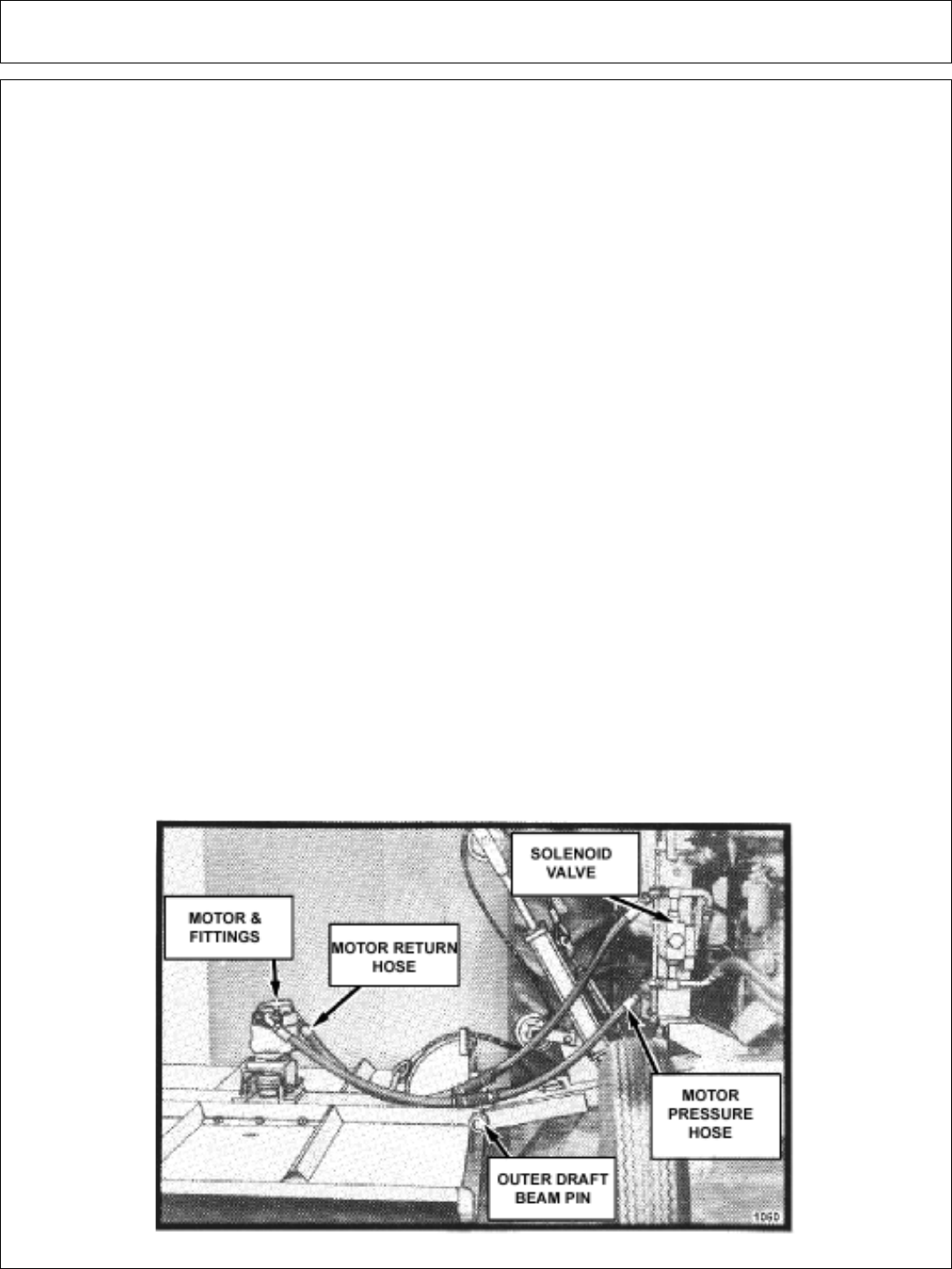
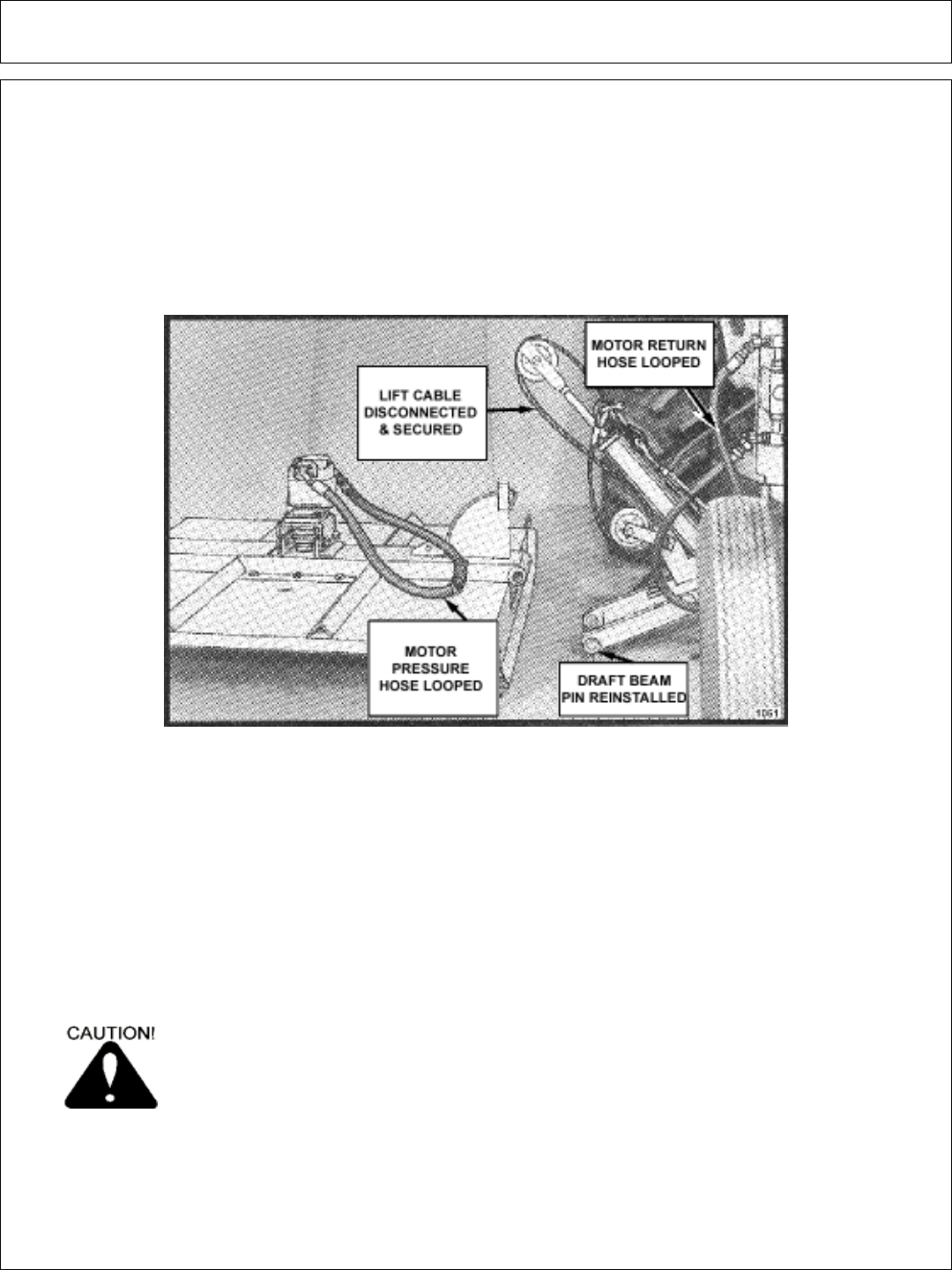
2: Transporting with side mower removed: Park the tractor and turn the engine
off. Remove the key to avoid accidental starting. Close ball valves on the hydraulic
reservoir. To avoid contaminating the hydraulic system, make sure all fittings on the
side mower motor and solenoid control valve are clean. Disconnect the motor
pressure hose at the solenoid valve and the motor return hose at the motor. See
diagram below.
Side Rtry Operation Section 3-7
OPERATION
Next, switch the hose ends and reconnect to form two separate closed loops, see
diagram below. Disconnect the lift cable from the head and secure the loose end back
onto the cable with the cable clevis. Remove the keeper bolt and draft beam outer pivot
pin. Separate the mower head from the tractor. Now reinstall the pivot pin and keeper
bolts into the draft beam to prevent loss. OPEN THE BALL VALVES ON THE
HYDRAULIC RESERVOIR BEFORE STARTING TRACTOR AGAIN! Serious damage
will be caused if tractor is started with the ball valves closed.
Use a loading dock or ramps to load the tractor onto the trailer, centering the
tractor between the sides of the trailer. Make sure the tractor (and rear mower) and
trailer are within legal transporting width. Lower the rear mower onto the trailer and
set the loose hide mower on the trailer. Secure the tractor and mowers to the trailer
with chains. Check the tractor operators manual for any requirements to transport
be flatbed trailer. Reverse this procedure to unload and remount the mowers after
transporting. Be sure all pins are secure, all connections are tight and any lost fluid
is replaced before using mowers. Use teflon tape when connecting all fittings.
If any part of this operating section, or any other section of this manual is
not completely understood, contact your Tiger dealer or the address on
the cover of this manual for assistance!

Side Rtry Operation Section 3-8
OPERATION
INSPECTION SHEETS

Side Rtry Operation Section 3-9
OPERATION
Rotary Mower PRE-OPERATION Inspection
Tractor ID#____________ Make_____________________
Date:__________________ Shift______________________
Before conducting the inspection, make sure the Tractor engine is off, all rotation
has stop and the tractor is in the Park with the parking brake engaged. The
Mower head is resting on the ground (or is securely blocked up and supported)
and all hydraulic pressure has been relieved.
Operators Signature:___________________________________________________________________
DO NOT OPERATE an UNSAFE TRACTOR or MOWER

Side Rtry Operation Section 3-10
OPERATION
TRACTOR PRE-OPERATION Inspection
Tractor ID#____________ Make_____________________
Date:__________________ Shift______________________
Before conducting the inspection, make sure the Tractor engine is off, all rotation
has stop and the tractor is in the Park with the parking brake engaged. The
Mower head is resting on the ground (or is securely blocked up and supported)
and all hydraulic pressure has been relieved.
Operators Signature:___________________________________________________________________
DO NOT OPERATE an UNSAFE TRACTOR or MOWER

Side Rtry Operation Section 3-11
OPERATION
FRONT END LOADER PRE-OPERATION Inspection
Mower ID#_____________ Make___________________
Date:__________________ Shift____________________
Before conducting the inspection, make sure the Tractor engine is off, all
rotation has stop and the tractor is in the Park with the parking brake
engaged. The Loader is resting on the ground (or is securely blocked up
and supported) and all hydraulic pressure has been relieved.
Operators Signature:___________________________________________________________________
DO NOT OPERATE an UNSAFE TRACTOR or FRONT END
LOADER

Side Rtry Operation Section 3-12
OPERATION
TRACTOR PRE-OPERATION Inspection
Tractor ID#____________ Make_____________________
Date:__________________ Shift______________________
Before conducting the inspection, make sure the Tractor engine is off, all
rotation has stop and the tractor is in the Park with the parking brake
engaged. The Loader is resting on the ground (or is securely blocked up
and supported) and all hydraulic pressure has been relieved.
Operators Signature:___________________________________________________________________
DO NOT OPERATE an UNSAFE TRACTOR or FRONT END
LOADER

MAINTENANCE
SECTION
Maintenance Section 4-1

Maintenance Section 4-2
MAINTENANCE
Tiger Mowers are designed for high performance and rugged durability, yet with
simplified maintenance. The purpose of this section of the manual is to help the
operator in the regular servicing of the mower. Regular maintenance at the
intervals mentioned will result in the maximum efficiency and long life of the Tiger
Mower.
When you purchase a Tiger Mower you also acquire another valuable asset,
Tiger’s parts organization. Our rapid and efficient service has guaranteed the
customer satisfaction for many years. Tiger parts keep up with the demands for
efficiency, safety and endurance expected of the Tiger Mower.
In addition to following the break in instructions for your particular tractor, the in-
tank hydraulic fluid filter should be replaced after the first 50 hours of service.
Thereafter the filter should be replaced every 500 hours, or yearly, which ever
comes first.
Re-torque wheel lugs after first five hours of operation and periodically
thereafter. See torque specifications listed in the tractor’s service manual for your
particular model. Wheel lugs must always be re-torqued whenever a wheel is
removed and reinstalled.
BREAK IN PERIOD
MAINTENANCE PRECAUTIONS
Be sure end of grease gun and zerks are clean before using. Debris injected
intobearings, etc. with grease will cause immediate damage.
DO NOT use a power grease gun to lubricate bearings. These require very
small and exact amounts of lubrication. Refer to the detailed maintenance section
for specificlubrication instructions. Do Not over-grease bearings.
Lexan windows should be washed with mild soap or detergent and luke warm
water, using a soft clean sponge or soft cloth. DO NOT use abrasive or alkaline
cleaners or metal scrapers on lexan windows!
Be alert to maintenance indicators such as the in-tank filter pressure gauge,
hydraulic reservoir sight gauge, etc. Take the required action to correct any
problems immediately.
Release of energy from pressurized systems may cause inadvertent actuation
of cylinders, or sudden release of compressed springs. Before disconnecting any
hoses relieve pressure by shutting tractor off, setting cutter on ground and actuating
lift valve handles.
DO NOT use hands to check for suspected leaks in hydraulic hoses!
Hydraulic fluid escaping under pressure can have sufficient force to
penetrate skin and cause serious injury. If fluid is injected into skin, it
must be surgically removed within a few hours or gangrene may result.
Use a small piece of wood or cardboard, not hands, to search for pin
hose leaks. Be sure all pressure is relieved whenever disconnecting
lines. Be sure all connections are tight and hoses and lines are not
damaged before applying pressure.

Maintenance Section 4-3
MAINTENANCE
REGULAR MAINTENANCE
The intervals at which regular servicing should be done are based on hours of
operation. Use the tractors hour meter to determine when regular servicing is
required. This symbol indicates a point that needs to be greased at an interval
noted in the section below. Refer to the Detailed Maintenance section
for further instructions on greasing. Copy and use the Daily
Maintenance sheet located at the end of this section.
DAILY OR EVERY 8 HOURS
ITEM SERVICE COMMENTS
Drive Shaft Yoke, U-Joint Grease Grease as instructed in
& Stub Shaft detailed maint. section
Pump Drive Shaft Check and Lube Insure drive shaft end play
Crankshaft Adapter Check rubber grommets Replace grommets if
damaged or missing
Pivot Points Lubricate Inject grease until it appears
at ends
Hydraulic Fittings Check for leaks Tighten when needed. Do Not
use hands to check for leaks,
see maintenance precautions
Knives Check Inspect for missing or
damaged knives, change
or sharpen as needed
Spindle mounting bolts Check 3/4” x 2” torque to 331 ft. lbs.
(spindle to deck)
Knife mounting bolts Check Pre-lubricate threads, then
(knife to disk) torque to 800 ft.lbs
Disk mounting bolts Check 5/8” x 1-3/4” bolt to torque
(disk to spindle) 204 dry or 184 oiled ft. lbs.
Belts Check / Adjust Check if broken, tighten
as required
Main Frame and Check Retorque bolts to torque
Deck specifications in this section
Hydraulic Fluid Level Check Add if required per fluid
recommendations

Maintenance Section 4-4
MAINTENANCE
WEEKLY OR EVERY 50 HOURS
ITEM SERVICE COMMENTS
In Tank Hyd. Fluid Change Change after first 50
Filter hours only, then every
(10 micron filter) 500 hours or yearly
In-Line High Pressure Change Change after first 50
Filter hours only, then every
(10 micron filter) 500 hours or yearly
MONTHLY OR EVERY 150 HOURS
Hydraulic Fluid Level Check Add as needed
Hyd. Tank Breather Clean / Check / Replace Clean or replace
Element as required
Rear Tire Type Max P.S.I.
480/80R38 29
18.4-34 26
18.4-38 26
YEARLY OR EVERY 500 HOURS
Spindle Grease Change
Motor to Spindle Spline Change
Hyd. Tank Fluid Change
In Tank Hyd. Fluid Filter Change
(10 micron filter)
In-Line HP Filter Change or Change when indicated
(10 micron filter) by restriction indicator.
Hyd. Tank Breather Change
TROUBLE SHOOTING
SYMPTOMS CAUSE REMEDY
Vibration 1. Loose bolts 1. Check all bolts and tighten
to torque specs. in this section
2. Cutter assembly 2a. Check for damaged blades,
disc. Unbalanced or cutter
shaft. Replace if needed.
2b. Check for wire, rope, etc.
entangled in cutter assembly
Mower will not lift 1. Hyd. Fluid low 1. Check and refill Hyd. Fluid.
2. Leaks in line 2. Tighten or replace fittings
and hoses
3. Faulty relief valve 3. Check pressure in line. Line
pressure in Control Valves
should be at least 2500 P.S.I.
4. Kinked or blocked 4. Clean or replace lines
5. Faulty cylinder 5. Inspect, repair or replace
cylinder

Maintenance Section 4-5
MAINTENANCE
SYMPTOMS CAUSE REMEDY
Oil Temperature rises 1. Low oil level 1. Bring oil to proper level
above 200 deg. F 2. Kinked/blocked hoses 2. Inspect / Repair / Replace
3. Worn pump / motor 3. Disable and repair
Mower will not start 1. Blown fuse 1. Check fuse between mower
or run switch and ignition / replace
2. Ball valves closed 2. Make sure valves are open
3. Low oil level 3. Check Hyd. tank and fill
4. Line leak 4. Check all fittings and lines.
Re-tighten or replace
5. Electronic 5a. Without the tractor running, turn
solenoid faulty the mower switch to on. A low
audible click should be heard if the
solenoid is engaging the solenoid
spool. If click is not heard, leave
switch in on position and with a
screwdriver or other steel object,
touch the small nut on the end of the
solenoid. If the metallic object is not
attracted to the nut, check the fuse
and wiring for an open circuit. If the
object is attracted but no “click” is
heard, replace the solenoid.
5b. Remove the four bolts holding the
small block to the main block. Lift
and remove small block being
careful not to damage O-rings / filter.
Clean filter and re-install.
5c. Remove large nut on side of large
valve block. Remove spring, and use
needle nose vise grip to pull spool
from block. Check block and spool
for contaminates and scratches.
Clean parts or replace if scratched.
Motor runs but 1. Belts 1. Inspect belts and pulleys. Replace
will not cut. belts and repair as needed.
2. Tensioner 2. Adjust tensioner nut until flat washer
washer is flush with top of guide.
Motor turns slowly 1. Contaminants 1. Remove large nut on side of large
or not at all. restricting spool valve block. Remove spring, and use
movement in needle nose vise grip to pull spool
valve body. from block. Check block and spool
for contaminates and scratches.
Clean parts or replace if scratched.
2. Suction lines 2. Check for kinkes or obstruction in
obstructed suction hose
3. Low oil level 3. Check Hyd. tank level and fill
Pump will not work 1. Excessive wear 1. Disassemble and repair.
on internal parts

Maintenance Section 4-6
MAINTENANCE
Motor will not work 1. Excessive wear 1. Disassemble and repair.
on internal parts
NOTE: If flow meter is available, check pressure and flow volume for all
suspected hydraulic problems.
If the solution to your problem cannot be found in this section, call the
Technical Service representative at the number shown on the front cover of
this manual.

Maintenance Section 4-7
MAINTENANCE
TORQUE SPECIFICATIONS
* These are intended to be general specifications. See tractor operators or service
manual for exact specifications for your unit.

Maintenance Section 4-8
MAINTENANCE
LUBRICATION RECOMMENDATIONS
Description Application General Specification Recomended
Mobil Lubricant
Tractor Hydraulics Reservoir JD-20C Mobilfluid 424
MF M1135,M1141
FNHM2C134D (FNH201)
Mower Hydraulics Reservoir
Cold Temperatures 0 F Start-Up ISO 46 Anti-Wear - Low Temp Mobil DTE 15M
Normal Temperatures 10 F Start-Up JD-20C Mobilfluid 424
MF M1135,M1141
FNH M2C134D (FNH201)
Normal Temperatures 15 F Start-Up ISO 46 Anti-Wear Mobil DTE 25
High Operating Temp. Above 90 F ISO 100 Anti-Wear Mobil DTE 18M
Flail Rear Gearbox Grease PAO Synthetic Extreme Mobil SHC 75W-90
Pressure Gear Lube Mobil 1 Synthetic Gear
Cutter Shaft & Ground Grease Lithium-Complex Mobilgrease CM-S
Roller Shaft (Flail) Gun Extreme Pressure
NLGI 2 - ISO 320
Drive Shaft Coupler Grease Lithium-Complex Mobilgrease CM-S
(Flail and Rotary) Gun Extreme Pressure
NLGI2 - ISO 320
Drive Shaft Yoke, U-Joint & Stub Shaft Grease Lithium-Complex Mobilgrease CM-S
Gun Extreme Pressure
NLGI2 - ISO 320
Boom Swivel Grease Lithium-Complex Mobilgrease CM-S
Boom Cylinder Pivots Gun Extreme pressure
(Rotary & Flail Boom) NLGI2 - ISO 320
Deck Boom Pivot & Grease Lithium-Complex Mobilgrease CM-S
Deck Stop Adjustment Gun Extreme pressure
(Rotary & Flail) NLGI 2 - ISO 320
Deck Spindle (Rotary) Grease Tiger Spindle Lubricant Mobilith SHC 220
Gun part number 06540000
9-13-02

Maintenance Section 4-9
MAINTENANCE
POLYCARBONATE CARE & MAINTENANCE
The proprietary UV and Abrasion Resistant surface coating on SHIELDS®
SUPERCOATED™ polycarbonate significantly improves performance. Periodic
cleaning using proper procedures and compatible cleaners are recommended to
prolong service life. Tiger Corp. polycarbonate is SUPERCOATED™ on both sides.
CLEANING THE SUPERCOAT™ HARD-COAT
1. Wash with a mild solution of soap or detergent and lukewarm water.
2. Using a soft cloth or sponge, gently wash the sheet to loosen dirt and grime and rinse well
with clean water.
3. To prevent water spotting, thoroughly dry with chamois or cellulose sponge.
4. Avoid the use of abrasive cleaners, squeegees and/or other cleaning implements that may
mar or gouge the coating.
CLEANING AGENTS WHICH HAVE BEEN FOUND TO BE COMPATIBLE UNDER LABORATORY
CONDITIONS:
•Aqueous Solutions of Soaps and Detergents
Windex1Top Job2Joy2Mr. Clean2
Fantastik3Formula 4094Sumalight D12 Brucodecid
•Organic Solvents
Butyl Cellosolve Kerosene Hexel, F.O. 554 Naphtha (VM&P grade)
Neleco-Placer Turco 5042
•Alcohols
Methanol Isopropyl
All residual organic solvents should be removed with a secondary rinse.
GRAFFITI REMOVAL
Butyl cellosolve (for removal of paints, marking pen inks, lipstick, etc.). The use of
masking tape, adhesive tape or lint removal tools works well for lifting off old weathered
paints.
To remove labels, stickers, etc., the use of kerosene or VM&P naphtha are generally
effective. When the solvent will not penetrate sticker material, apply heat (hair dryer) to
soften the adhesive and promote removal.
IMPORTANT: If a material is found to be incompatible in a short-term test, it will usually be
found to be incompatible in the field. The converse, however, is not always true. Favorable
performance is no guarantee that actual end-use conditions have been duplicated.
Therefore, these results should be used as a guide only and it is recommended that the
user test the products under actual end-use conditions.
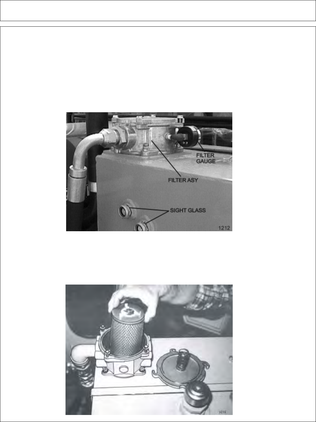
Maintenance Section 4-10
MAINTENANCE
RECOMMENDED FILLING INSTRUCTIONS
FOR HYDRAULIC RESERVIORS
When filling or checking the oil level, the unit should be parked on a level
surface, shut “OFF”, and allowed sufficient time to cool to ambient temperature.
Use caution when removing the pressurized breather. Do not place face over opening
when removing the breather.
The reservior should be filled to the top of the lower sight glass on the side of the
tank. Do not over-fill. The reservior has been over-filled when oil is visible in the upper
sight glass. If tank has too much oil, the excess may be expelled through the pressurized
breather.
DETAILED MAINTENANCE
REPLACEING IN-TANK HYDRAULIC FILTER:
Loosen the four bolts on the top cover of the filter housing. Turn cover
counter-clockwise until cover is free. Remove and replace filter. Replace
top cover and cover bolts in opposite order as removed.

Maintenance Section 4-11
MAINTENANCE
DETAILED MAINTENANCE
REPLACEING HIGH PRESSURE HYDRAULIC FILTER ELEMENT:
Assure system has been shut down and de-pressurized. Locate High Pressure
Filter housing. Confirm that the element that is about to be installed matches the
element p/n on the filter model tag. Example: V3.0510-06 (world line 100, HD049
model) Locate the bottom of the High Pressure Bowl, and use the appropriate
spanner wrench –or- ratchet that matches the hex pattern. Using the spanner
wrench -or- ratchet and turning in a counterclockwise rotation, (looking at the bottom
of the bowl) remove the bowl from the head, The first couple rotations will seam
tight as the o-ring passes the sealing flats, once the o-ring has cleared the sealing
flats the bowl should spin freely. Taking care not to drop the bowl, finish removing
the bowl from the head. WARNING: bowl will be full of oil! Pour the oil from the
bowl into a container, this oil should be considered contaminated due to the flow
direction through the element is outside ~ in. Clean the inside of the bowl if “dirt” is
present. Remove the old element from the filter head by pulling with a rotation
motion. Dispose of the used element properly. Remove the new element from the
packaging. Using your finger, dab and lubricate the o-ring in the top of the new
element. Install the new element into and on the mounting boss with in the head;
assure that the element is fully seated on the boss. Clean and inspect the o-ring
that is affixed in the bowl, lubricate with oil. Using a clockwise rotation, screw the
bowl back into the head, assuring that the bowl has not been cross threaded into the
head. Continue “tighten” the bowl into the head, using the spanner wrench –or-
ratchet, the rotation of the bowl will become tighter once the o-ring engages the
sealing flats. Once the bowl has been fully inserted into the head, and the o-ring has
reached the sealing flats, the bowl can no longer be “tightened” and bottoms out.
Once the bowl has bottomed out, “back-off” the bowl by 1/6 turn, this assures that
the o-ring is seated properly with in the sealing flats. Element change out and re-
assembly is now complete. Start the machine and inspect the filter area checking
that there is no oil leaking from the filter assembly. This is first to be done at 50
hours of operation, then yearly(500 hours) or when indicated by restriction indicator.
BOWL
HEAD
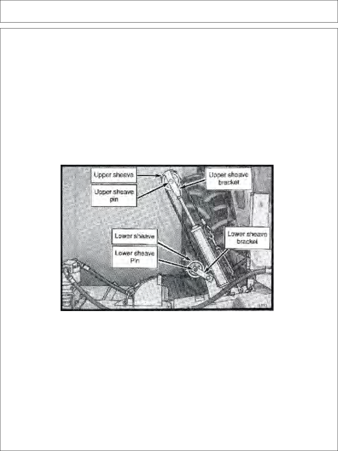
Maintenance Section 4-12
MAINTENANCE
GREASING INNER AND OUTER DRAFT BEAM
PIVOT POINTS
Locate the grease zerks on the inner and outer draft beam pivot bosses. Inject
Lithium-Complex Extreme Pressure grease conforming to NLGI2-ISO 320
specifications into each zerk until grease protrudes from joints. Grease all pivots
daily or every 8 hours of service.
GREASING THE UPPER AND LOWER SHEAVES
Locate the grease zerks on the ends of the upper and lower sheave pins as
shown below. Inject Lithium-Complex Extreme Pressure grease conforming to
NLGI2-ISO 320 specifications into each pin until it protrudes from the ends. These
should also be greased daily or for every 8 hours of service.
GREASING INNER AND OUTER DRAFT BEAM
PIVOT POINTS
Locate the grease zerks on the inner and outer draft beam pivot bosses. Inject
Lithium-Complex Extreme Pressure grease conforming to NLGI2-ISO 320
specifications into each zerk until grease protrudes from joints. Grease all pivots
daily or every 8 hours of service.
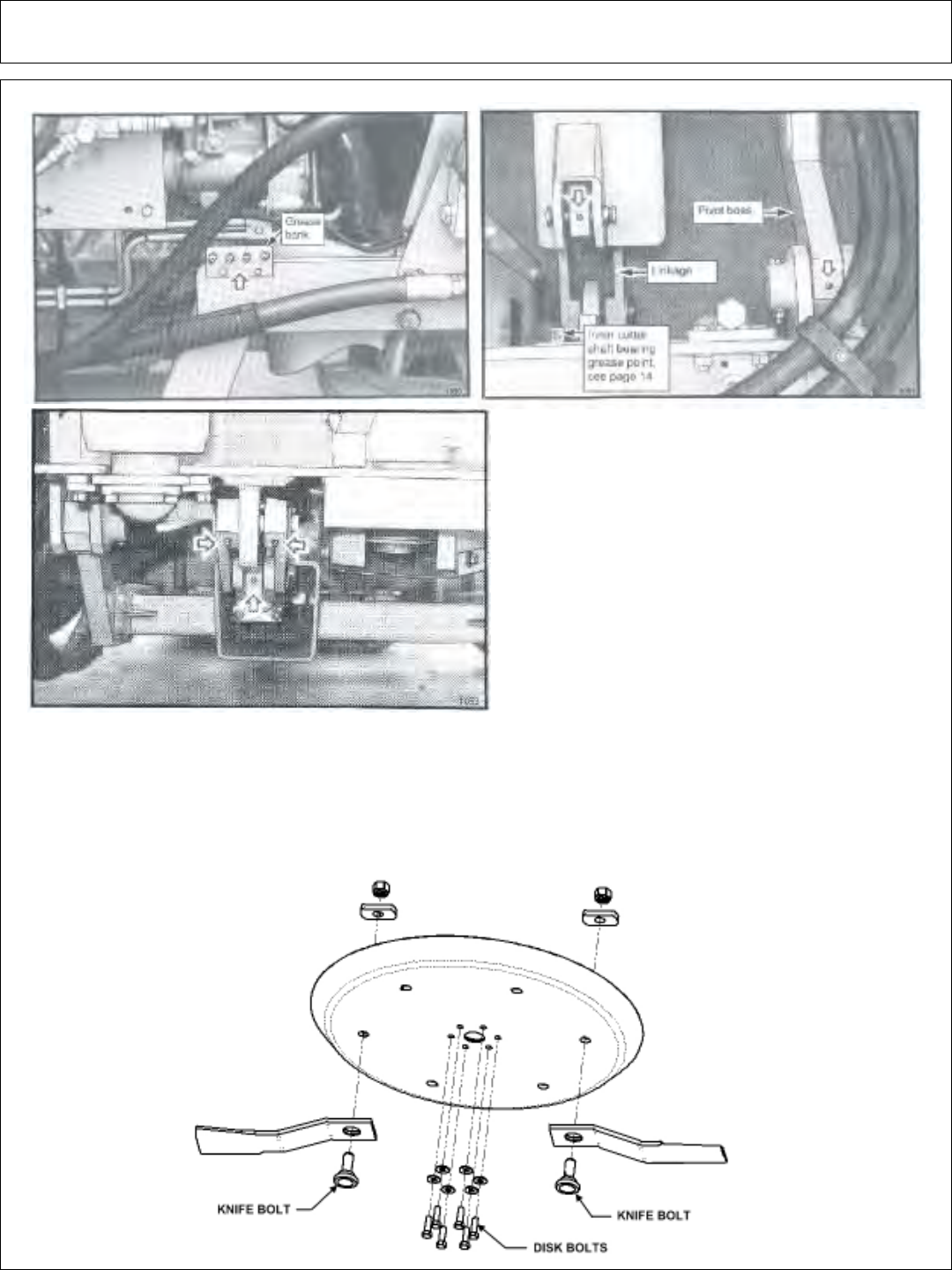
Maintenance Section 4-13
MAINTENANCE
With the cutter head lowered, locate the
grease zerks on the linkage and pivot bosses.
Inject Lithium-Complex Extreme Pressure
grease conforming to NLGI2-ISO 320
specifications until it protrudes from the ends.
With the cutter head in this position it is also
possible to grease the draft beam cylinder
anchors and pins. Now raise the cutter head
to expose the remaining zerks on the deck tilt
linkages and on the other end of the cylinder.
TIGHTENING KNIFE BOLTS AND DISK BOLTS:
After every 8 hours of operation or daily, the Knife Bolts and Disk Bolts should be
tightened as follows:
Knife mounting bolts (2ea.) torque oiled to 800 ft. lbs.
Disk mounting bolts (6ea. ) torque dry to 204 or oiled to 184 ft. lbs.
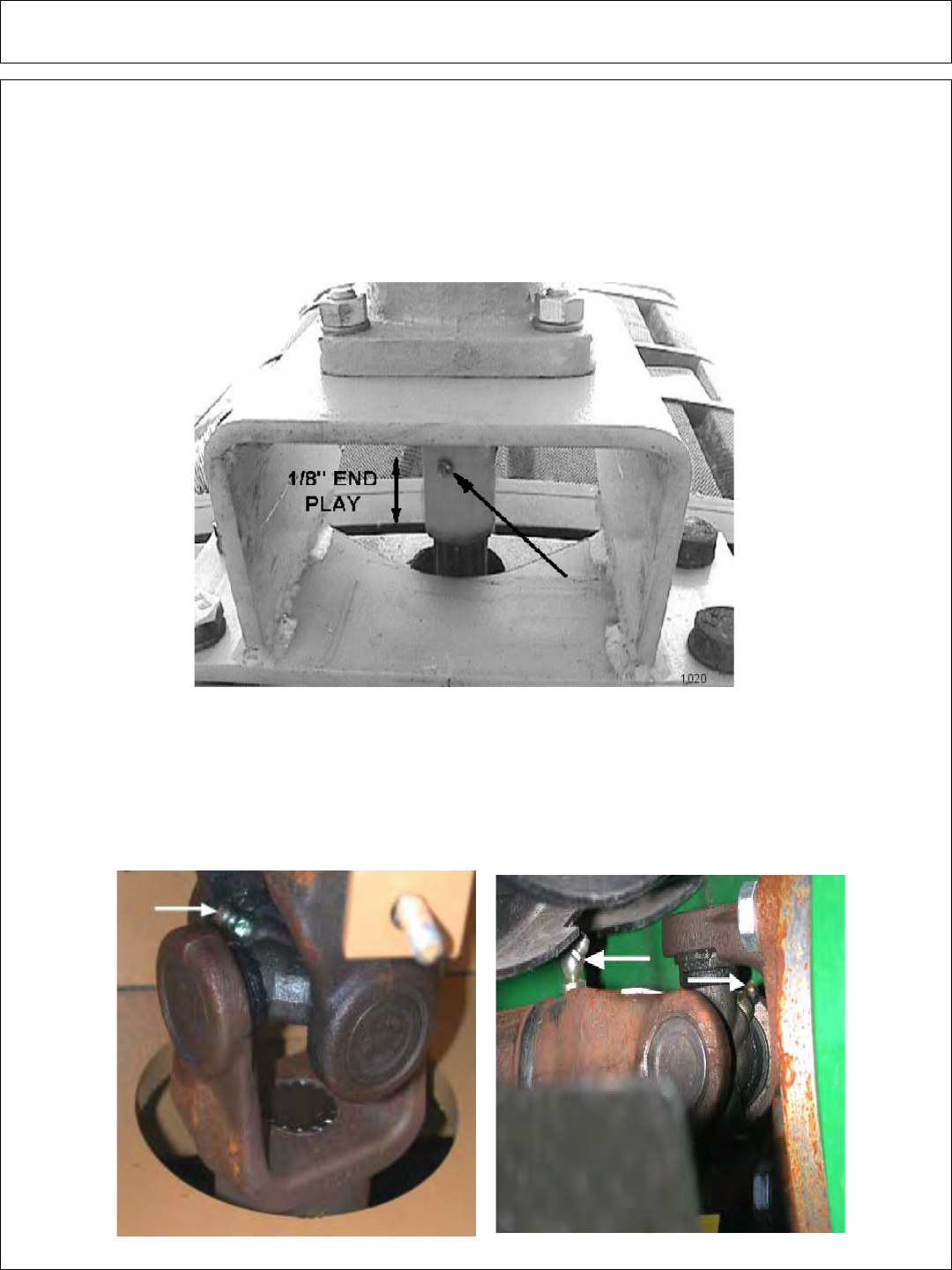
Maintenance Section 4-14
MAINTENANCE
GREASING PUMP DRIVE SHAFT COUPLER:
With engine stopped, ensure drive shaft alignment by grasping coupler and sliding
back and forth. Coupler should slide freely with approximately 1/8” of end play. If
coupler does not slide freely, inspect for loose pump mount bolts, or damaged or
loose crank shaft adapter. Inject Lithium-Complex Extreme Pressure grease
conforming to NLGI2-ISO 320 specifications into coupler until grease begins to
protrude from ends. Grease daily or every 8 hours. Do not over grease.
DRIVE SHAFT YOKE, U-JOINT & STUB SHAFT
With engine stopped, inject Lithium-Complex extreme pressure grease
conforming to NLGI2-ISO 320 specifications into universal joints and slip yoke untill
grease appears at the seal. Grease them daily or every 8 hours.
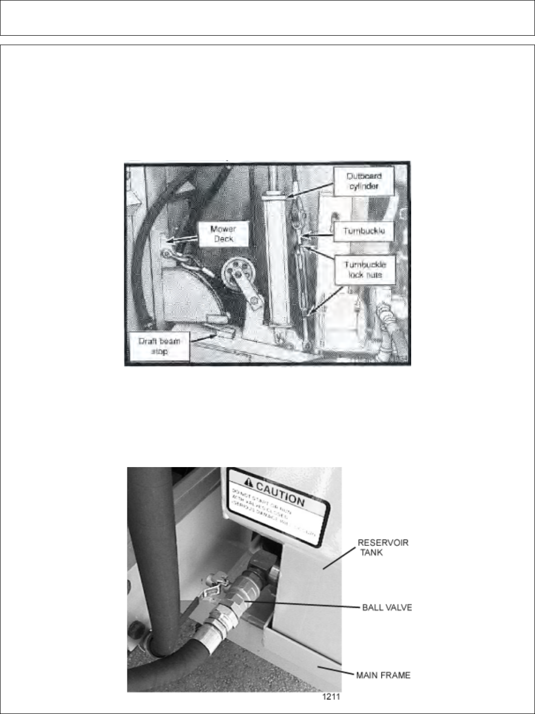
Maintenance Section 4-15
MAINTENANCE
BALL VALVES
The ball valve at the hydraulic reservoir may need to be closed during certain
maintenance or repair procedures. THE BALL VALVES MUST BE OPEN (handle
parallel with valve) WHEN TRACTOR IS RE-STARTED OR PUMP IS COUPLED
TO MOTOR OR P.T.O. ! Failure to do so may result in component failure!
ADJUSTING THE CABLE LIFT
Extend the outboard cylinder until the mower deck touches its stop on the draft
beam as shown. NOTE: Make sure the cable turnbuckle is loose enough to allow
the cylinder to reach full extension before the head reaches the stop. Now hold the
head against the stop and tighten the turnbuckle until the cable is tight. Lower and
raise the head to check the adjustment. The head should touch its stop at the same
time the cylinder reaches full extension. Tighten turnbuckle lock nuts securely after
adjustment is complete.
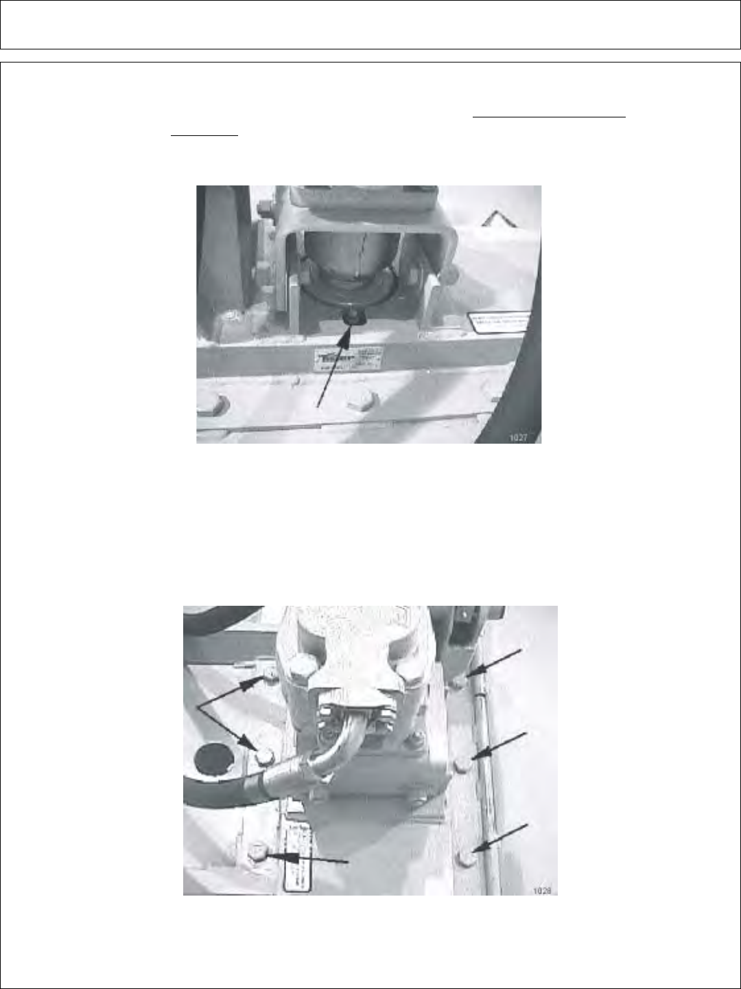
Maintenance Section 4-16
MAINTENANCE
GREASING SPINDLE
Locate grease fitting on inside of deck housing. Inject Tiger Spindle Lubricant,
part number 06540000 into spindle housing. Fill with lubricant until lubricant weeps
out of the top spindle seal. Lubricate spindle weekly or every 40 hours of use.
TIGHTENING SPINDLE BOLTS
The spindle mounting bolts should be checked and retorqued daily or every 10
hours of service. Torque the (6) bolts shown below to 331 ft. lbs.
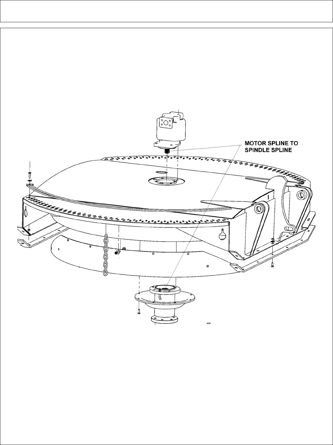
Maintenance Section 4-17
MAINTENANCE
GREASING MOTOR SPLINE TO SPINDLE
SPLINE
Locate motor spline and spindle spline on the mower deck. Grease splines with
Mobil moly 52. Use about 4 ounces of grease. Change grease yearly or every 500
hours.

Maintenance Section 4-18
MAINTENANCE
ROTARY KNIFE REPLACEMENT
1 – Be sure you have a complete matching set of new knives for replacement.
2 – Remove knives and inspect holes for damage. Also watch for cracks in the disk
around the holes.
3 – Lube threads with anti-seize, motor oil or grease. Install bolt through knife and
disk from bottom side of disk. Install new self-locking nuts and torque them to
800 oiled ft. lbs.
4 – The knives should swing freely to absorb shocks from impact when striking
objects.
WHEN CUTTING HEAVY BRUSH, KNIFE BOLTS SHOULD BE
INSPECTED HOURLY AND RETORQUED TO 1070 dry or 800 oiled
FT. LBS.
INSPECTION OF ROTARY KNIVES
Failure to follow the following warnings and instructions may result
in serious injury or damage to the equipment or property!
1 – DO NOT weld on the knife or bolts. Damaged or worn knives must be replaced.
2 – Knife must be replaced in sets. Knives with unequal wear may cause serious
vibration and resulting structural damage to the mower.
3 – The self-locking nuts for the knife mounting bolts must NOT be reused. If the
self-locking nut is removed from the knife mounting bolt, the nut must be replaced
with a new self-locking nut.
4 – Inspect the condition and tightness of the knife mounting bolts and disk mounting
bolts daily.

Maintenance Section 4-19
MAINTENANCE
REPLACEMENT OF ROTARY DISK
Failure to follow the following warnings and instructions may result
in serious injury or damage to the equipment or property!
The bolts that attach the knife mounting disk to the spindle must be grade 8.
These 5/8 inch bolts are to be torqued to 204 dry or 184 oiled ft. lbs.
A thread locking agent may be applied to threads of all mounting bolts before they
are installed.
Disks must be inspected daily for hairline cracks between spindle
mounting bolts or around the knife mounting bolts. These cracks indicate
metal fatigue caused by severe abuse. If cracks are present, the disk must be
replaced.
Inspect the disk mounting bolts daily when checking tightness of blade mounting
bolts. If a disk mounting bolt is loose, it must be removed, threads cleaned, fresh
thread locking agent applied, and tightened to proper torque value.
If a knife mounting bolt is loose, the self locking nut must be replaced as a safety
precaution. Lubricate threads with anti-seize, grease or motor oil. Place bolts
through knife and disk from bottom side of disk. Install self locking nuts and torque
them to 800 ft. lbs.
1- WARNING: The disk alone weighs approximately 210 lbs. Be sure its weight
can be supported before attempting to replace. The use of a lift mechanism will
ease replacement.
2- Remove the six disk mounting bolts and the disk from the spindle.
3- Install new disk and align with mounting bolt holes.
4- Apply a thread locking agent to all of the mounting bolts and install the bolts
through the disk. If a bolt protector is being installed, hold the protector in place and
install the bolts through the bolt protector and disk. NOTE: Disk bolts must be
Grade 8.
5- Tighten bolts down and torque to values noted.
6- See knife replacement instructions for replacing the knives onto the new disk.
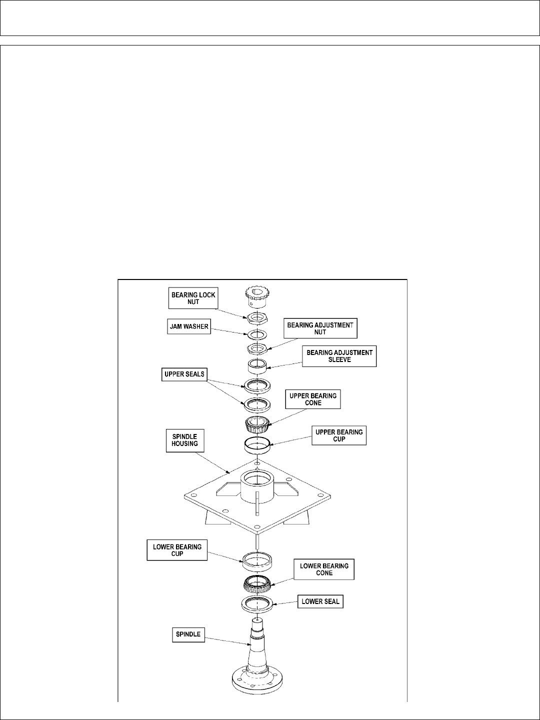
Maintenance Section 4-20
MAINTENANCE
HEAVY DUTY SPINDLE ASSEMBLY
INSTALLATION AND BEARING ADJUSTMENT
WARNING! A press MUST be used to install bearing cups, bearing cones, and
seals. DO NOT use a hammer to install races, bearings, or seals. The parts of
assembly may be damaged.
NOTE: The grease zerk and gussets are located on the top side of the spindle
housing. Be sure the spindle is assembled correctly.
Be sure to wear eye protection and other protective equipment as needed
when working on spindle assembly.
THE SPINDLE ASSEMBLY
See the diagram below for identification of spindle parts, while servicing.
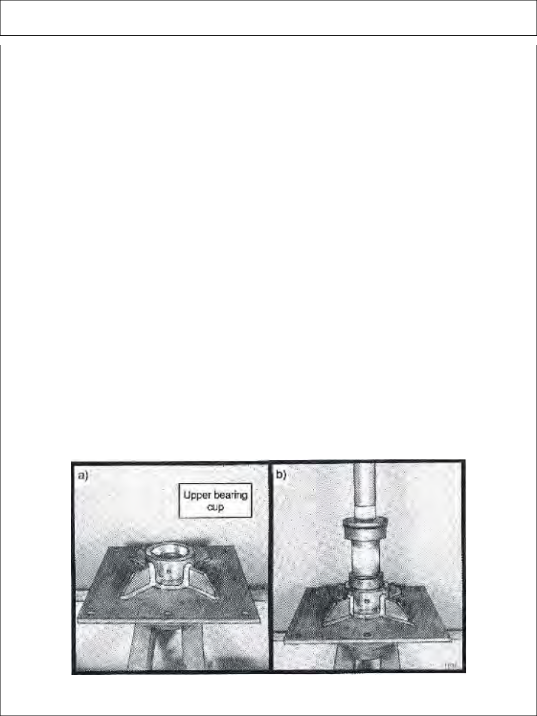
Maintenance Section 4-21
MAINTENANCE
BEARING INSTALLATION
1 – Press upper bearing cup into the spindle housing.
2 – Turn the spindle housing over and press in the lower bearing cup.
3 – Place the lower bearing cone in the bearing cup. Next press the seal into the
spindle housing. The inner lip of the seal must be DOWN, towards the bearing, so
lubricant is sealed inside the housing.
4 – Install the spindle in the housing. Lightly press the spindle to seat the cone onto the
spindle.
5 – Support the bottom of the spindle and press the upper bearing cone and bearing
adjustment sleeve onto the spindle.
NOTE: The spindle housing must turn freely when seating the bearing cone and sleeve.
6 – Press the two upper seals into the spindle housing. The inner lip of the seals must
be UP, away from the bearing, so excess lubricant can escape.
7 – Install the bearing adjustment nut (thin nut) so there is 1/16” clearance between the
nut and the sleeve. Install the jam washer, placing the tab into the key-way. Install the
bearing lock nut (thick nut) and hand tighten against jam washer and adjustment nut.
See the following section for bearing adjustment.
8 – Position the spindle housing horizontally with the drain hole oriented “up.” Grease
through the zerk with Tiger Spindle Lubricant(part number 06540000) until the grease
purges from the drain hole.
9 – Install the plug into the drain hole.
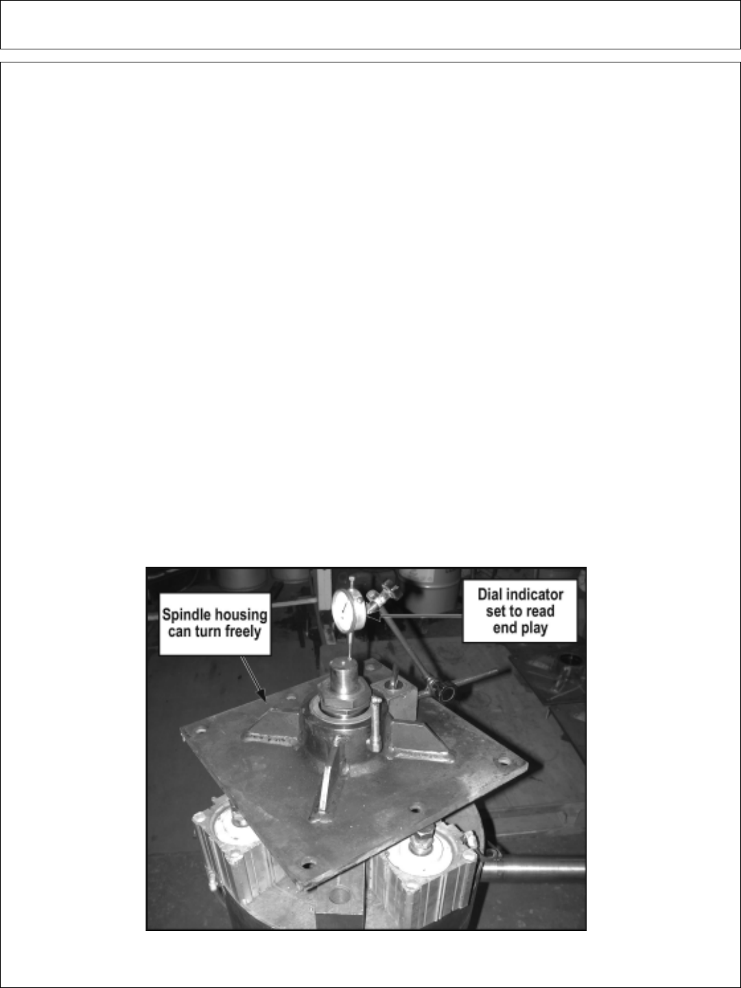
Maintenance Section 4-22
MAINTENANCE
BEARING ADJUSTMENT
1 – Clamp the bottom end of the spindle securely in a vise so the spindle housing
turns freely.
2 – Position a magnetic base dial indicator on the outer diameter of the spindle
housing. Locate the end of the dial indicator against the flat end of the spindle shaft.
The dial indicator will now measure accurately bearing end play.
3 – Tighten the bearing adjustment nut until there is .012 inch movement when the
spindle housing is pried upward away from the vise jaws.
4 – When there is .012 inch free play between the spindle and housing, install the
bearing lock nut (thick nut). Hold the adjusting nut securely and tighten the lock nut
to 300 ft. lbs. of torque.
5 – After the lock nut is tightened, there must be .001 inch to .003 inch of free play
when lightly prying up on the spindle housing.
If the end play is correct, .001 inch to .003 inch, bend tabs up on jam washer to
prevent the lock nut from loosening.
If the end play in NOT correct, loosen the lock nut and turn the adjustment nut as
required and re-tighten the lock nut. Repeat first part of step 5.

Maintenance Section 4-23
MAINTENANCE
DAILY MAINTENANCE SCHEDULE
The following services should be performed daily or every 8 hours
of service, following the detailed maintenance instructions in the
operators manual.
______ Pump Drive Shaft: Check for end play in drive shaft / coupler and
lubricate at zerks.
______ Crankshaft adapter: If equipped with rubber grommets check
condition, replace if missing or damaged.
______ Pivot points: Inject grease until it appears at ends.
______ Hydraulic fittings: Check for leaks with paper or cardboard. Tighten
fittings or replace hoses immediately.
______ Knives: Inspect for missing or damaged knives, change (only
complete sets) as needed.
______ Belts: Check / Tighten / Replace belts as needed.
______ Main Frame / Deck: Unless otherwise specified retorque bolts
according to torque specifications in this
section.
______ Hydraulic Fluid Level: Add, if required, per fluid recommendations.
______ Rear Flail Drive, Bearing
Flange and Shaft Couplers: Grease as instructed in the detailed
(if applicable) maintenance section.
______ Cutter Shaft and Ground Roller: Grease as instructed in the detailed
maintenance section
Service performed by:_______ Date:____/____/____ Hour
Meter:__________
Maintenance Section
** This page may be copied and used as part of the daily maintenance routine.

Maintenance Section 4-24
MAINTENANCE

PARTS
SECTION
SIDE ROTARY KUBOTA M105X
Parts Section 5-1

Parts Section 5-2
The following instructions are offered to help eliminate needless delay and error in
processing purchase orders for the equipment in this manual.
1. The Parts Section is prepared in logical sequence and grouping of parts that
belong to the basic machine featured in this manual. Part Numbers and
Descriptions are given to help locate the parts and quantities required.
2. The Purchase Order must indicate the Name and Address of the person or
organization ordering the parts, who should be charged, and if possible, the serial
number of the machine for which the parts are being ordered.
3. The purchase order must clearly list the quantity of each part, the complete
and correct part number, and the basic name of the part.
4. The manufacturer reserves the right to substitute parts where applicable.
5. Some parts may be unlisted items which are special production items not
normally stocked and are subject to special handling. Request a quotation for such
parts before sending a purchase order.
6. The manufacturer reserves the right to change prices without prior notice.
NOTE: When ordering replacement decals, refer to the part numbers and
descriptions listed in the safety section in the front of this manual.
For maximum safety and to guarantee optimum product reliability,
always use genuine Tiger replacement parts. The use of inferior
replacement parts may cause premature or catastrophic failure
which could result in serious injury or death.
Direct any questions regarding parts to:
Tiger Corporation
3301 N. Louise Ave.
Sioux Falls, SD 57107
1-800-843-6849
1-605-336-7900
PARTS ORDERING GUIDE

Parts Section 5-3
PARTS SECTION TABLE OF CONTENTS
SECTION ASSEMBLY PAGE
TRACTOR SPECIFIC PARTS:
TRACTOR MNT. KIT - MAIN FRAME M105X 06101300 5-4
TRACTOR MOUNT KIT - HYDRAULICS M105X 06101300 5-6
COMBO DRAFT BEAM 5-8
2SP HUSCO CONTROLS - KUBOTA M105X 5-10
2SP HUSCO LIFT VALVE - COMBO 06101302 5-12
2SP HUSCO LIFT VALVE - CABLE 06101312 5-14
HUSCO VALVE BREAKDOWN 30801 5-16
HUSCO VALVE BREAKDOWN 31752 5-18
SAFETY SCREEN - KUBOTA M105X 06101307 5-20
OPTIONAL PUMP GUARD KIT 06200342 5-22
OPTIONAL PUMP AND GRILL GUARD KIT 06200349 5-23
FUEL TANK - KUBOTA M105X 06101300 5-24
SWITCH BOX SCHEMATIC 06510102 5-25
SOLENOID BRAKE VALVE ASSEMBLY 34115 5-26
SOLENOID BRAKE VALVE HYDRAULIC SCHEM. 34115 5-27
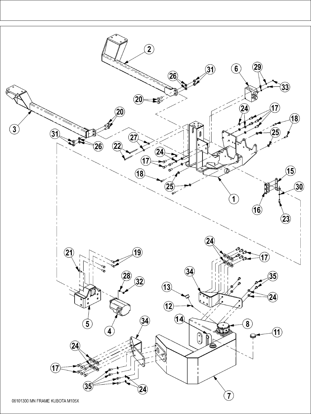
Parts Section 5-4
TRACTOR MOUNT KIT - MAIN FRAME M105X
5-22-06

Parts Section 5-5
TRACTOR MOUNT KIT - MAIN FRAME M105X
ITEM PART NO. QTY. DESCRIPTION
1 06300043 1 MNFRM,KUB,M105X
2 06300044 1 AXL BRC,LH,KUB,M105X
3 06300045 1 AXL BRC,RH,KUB,M105X
4 23152 1 PUMP,P350-1 3/4 GEAR
5 06380026 1 PUMP MNT,KUB,M105S
6 06510083 1 VALVE,BRAKE,SOL,3000PSI,METRI
34666 * TANK,RES,BUMP,BLANK,CPLT,ASSY
7 33695 1 TANK,RES,BUMPER,BLANK
8 35269 1 FILTER ASSY,IN-TANK,JIC,10MIC
10 21627 4 NYLOCK NUT,3/8 NC
11 06505077 1 CAP,PRESSURE,3.0PSI
12 TF4887 1 STREET ELBOW,1/8 X 45
13 6T0649 1 FILTER GAUGE
14 06505067 1 SIGHT GLASS,TANK
15 06410394 1 MOUNT,HOSE CLAMP
16 35131 1 CLAMP KIT,COOLER,TRUCKAT
*17 06530531 20 CAPSCREW,18MMx40MM(1.5P)GR8.8
18 06530530 12 CAPSCREW,M14xM55(1.5P),GR 8.8
19 6T2521 4 CAPSCREW,16MMX40MM(1.5 PITCH)GR8.8
20 21833 4 CAPSCREW,3/4 X 2-1/4 NC
21 21732 4 CAPSCREW,1/2 X 1-3/4 NC
22 21644 2 CAPSCREW,3/8 X 5 NC
23 21730 1 CAPSCREW,1/2 X 1-1/4 NC
24 33764 32 FLATWASHER,5/8,GR 8,SAE
25 06533003 12 FLATWASHER,9/16 GR 9 SAE
26 33880 4 FLATWASHER,3/4,GR 8,SAE
27 22016 2 FLATWASHER,3/8
28 21990 4 LOCKWASHER,1/2
29 21988 2 LOCKWASHER,3/8
30 21989 1 LOCKWASHER,7/16
31 21825 4 HEX NUT,3/4 NC
32 21725 4 HEX NUT,1/2 NC
33 21625 2 HEX NUT,3/8 NC
34 06380025 2 TANK MNT,KUB,M105S
35 21780 8 CAPSCREW,5/8 X 1-1/4 NC
* - NOTE: TORQUE #18 CAPSCREWS TO 155 FT. LBS. - DRY & 122 FT. LBS. -
LUBRICATED. THESE ATTACH THE FRONT OF THE MAIN FRAME TO THE
TRACTOR FRAME.
5-22-06
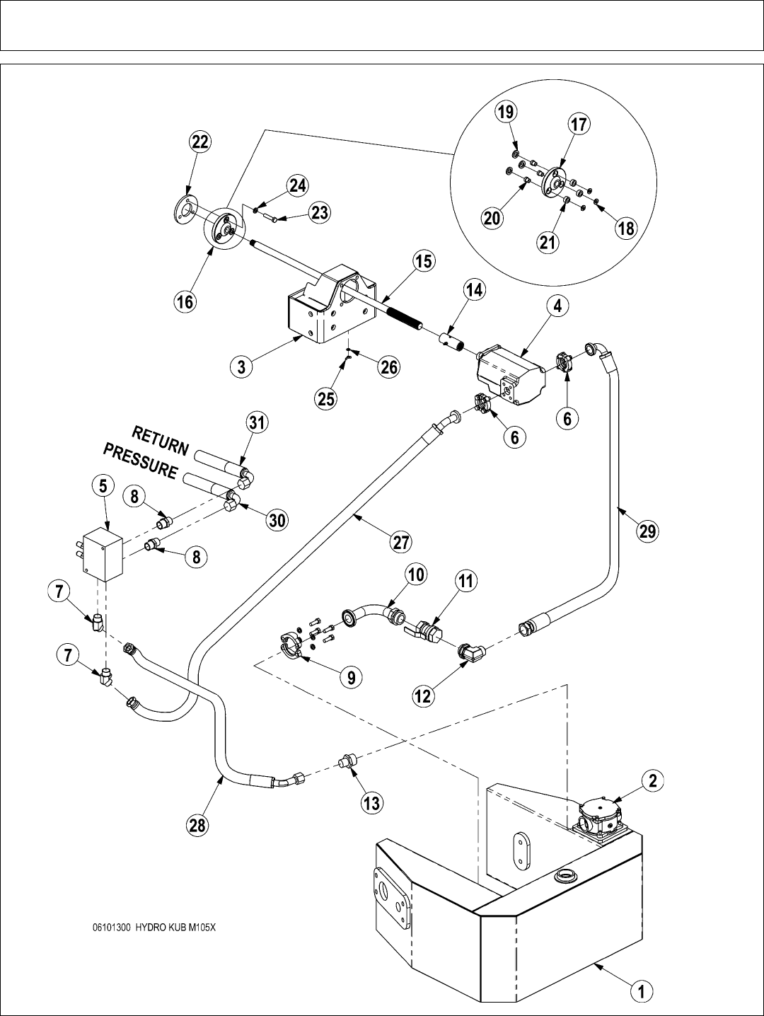
Parts Section 5-6
TRACTOR MOUNT KIT - HYDRAULICS M105X
5-24-06

Parts Section 5-7
TRACTOR MOUNT KIT - HYDRAULICS M105X
ITEM PART NO. QTY. DESCRIPTION
1 33695 1 TANK,RES,BUMPER,BLANK
2 35269 1 FILTER ASSY,IN-TANK,JIC,10MIC
3 06380026 1 PUMP MNT,KUB,M105S
4 23152 1 PUMP,P350-1 3/4 GEAR
5 06510083 1 VALVE,BRAKE,SOL,3000PSI,METRI
6 TF4852 2 KIT,FLANGE,#20
7 33554 2 ELBOW,1MORBX1MJIC,45
8 33555 2 ADAPTER 1” MORB X 1” MJIC
9 TF4431 1 KIT,FLANGE,#32
10 34389 1 ELBOW,1 1/2ORBX32FLG90
11 34309 1 BALL VALVE,1 1/2 FOR
12 06503054 1 ELBOW,1 1/2 ORB x 1 1/4 MJ
13 34064 1 ADAPTER,1 1/4MOR X 1MJ
14 6T0375B 1 COUPLING,14 SPLINE,W/ZERK,4
15 06420045 1 DRV SHF,PMP,38.08,KUB
16 06700043 * ADAPTER,CRANKSHAFT,KUB,M105X
17 6T0450 1 CRNKSHFT ADPT,KUB 7030
18 24937 3 FLATWASHER,7/16,SAE
19 06537004 3 WASHER,NEOPRENE,.75x1.25x.19
20 6T3202 3 GROMMET,STEEL,12MM
21 6T3218 3 GROMMET,RUBBER
22 06400393 1 SPACER,CRNKSHFT ADPTR,KUB,M105
23 24962 3 CAPSCREW,12MMX55MM(1.25 PITCH)
24 27724 3 LOCKWASHER,12MM
25 32519 1 NUT,WING,1/4-20 UNC
26 22014 1 FLATWASHER,1/4
27 06500248 1 HOSE,1x77(1FJX45x1FJX
28 06500249 1 HOSE,1x92(1FJXx1FJX90)
29 06500214 1 HOSE,1 1/4x29(1 1/4FJXx20FLG90
30 34161 1 HOSE,1X101 (60” CABLE LIFT)
* 34154 REF HOSE,1X96 (60” COMBO LIFT)
* 34638 REF HOSE,1X107 (72” CABLE OR COMBO LIFT)
31 34162 1 HOSE,1X98 (60” CABLE LIFT)
* 34155 REF HOSE,1X96 (60IN COMBO LIFT)
* 34639 REF HOSE,1X104 (72” CABLE OR COMBO LIFT)
5-24-06
NOTE:1. Clamp the hose from the pump to the brake valve and the hose
from the brake valve to the tank to the hose bracket.
2. Band hoses together with zip ties wherever loose. Where hoses
may contact the frame or other edges, wrap with split hose and
secure with hose clamps or zip ties.
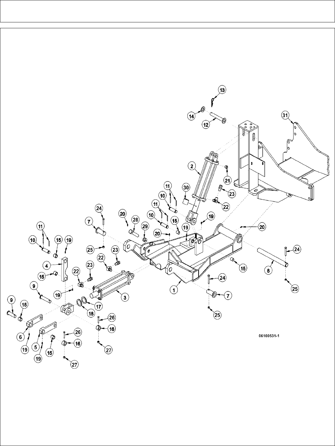
Parts Section 5-8
COMBO DRAFT BEAM

Parts Section 5-9
COMBO DRAFT BEAM
ITEM PART NO. QTY. DESCRIPTION
1 32143 1 BEAM,DRAFT,JD5520-25
2 6T0151R 1 HYD. CYLINDER 3” X 10”
3 32215 1 HYD. CYLINDER 3” X 12”
4 TF4500A 1 PIVOT ARM
5 TF4507B 1 RIGHT LINKAGE ARM
6 TF4506B 1 LEFT LINKAGE ARM
7 30126B 2 PIN,DRAFT BEAM
8 6T3001 1 PIN, BEAM PIVOT
9 TF4519 2 PIN, LINKAGE
10 6T3003D 3 PIN, CLEVIS (DRILLED)
11 TB1023 6 ROLLPIN 7/32” X 2”
12 6T3002A 1 PIN, LIFT CYLINDER
13 6T3004 2 R-CLIP HAIRPIN
14 22023 2 FLATWASHER 1”
15 23724 8 BUSHING 1”
16 22847 2 BOSS, LINKAGE PIN
17 22076 1 SPACER, HYD. CYLINDER 1”
18 22077 1 SPACER, HYD. CYLINDER 1/2”
19 6T3207 5 GREASE ZERK 1/4”
20 6T3211 3 GREASE ZERK 1/8”
21 6T4258 1 BREATHER 1/2”
23 34244 3 ELBOW FITTING 1/2”
24 34396 3 SWIVEL RESTRICTOR
27 21688 3 CAPSCREW 7/16” X 3 1/4”
29 21677 3 NYLOCK NUT 7/16”
30 21635 2 CAPSCREW 3/8” X 2 1/4”
31 21627 2 NYLOCK NUT 3/8”
33 21831 1 CAPSCREW 3/4” X 1 3/4”
34 21825 1 HEX NUT 3/4”
35 30781 1 CYLINDER SPACER W/SET SCREW
36 * REF REFER TO MAIN FRAME
NOTE:
ITEM 35 IS USED ON THE GLAND END OF ITEM 2 (AS NEEDED)
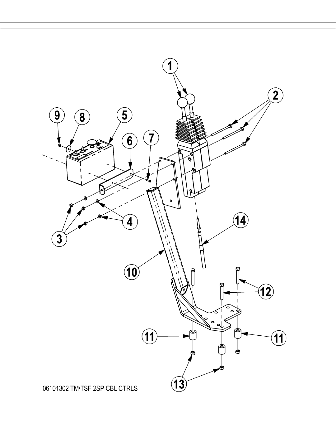
Parts Section 5-10
2 SPOOL HUSCO CONTROLS - KUBOTA M105X
4-27-06

Parts Section 5-11
2 SPOOL HUSCO CONTROLS - KUBOTA M105X
ITEM PART NO. QTY. DESCRIPTION
16T1251 2CBL CTRL BOX,180 DEG
221542 3 CAPSCREW,1/4 X 4 NC
321525 3 HEX NUT,1/4 NC
421986 3 LOCKWASHER,1/4
506510102 1 SWITCHBOX,SIDE,GND
634496 1 BRKT,SWITCHBOX,UNI
732359 2 SCREW,MACHINE,8-32X3/4
834508 2 WASHER,FENDER,#10
96T3952 2 HEX NUT,8/32 NYLOCK
10 23865B 1 CBL CTRL MT BRK,9030-FD40-JD60
11 27082B 3 SPACER
12 21636 3 CAPSCREW,3/8 X 2-1/2 NC
13 21627 3 NYLOCK NUT,3/8 NC
14 34623 2 CBL,CNTRL,122
4-27-06
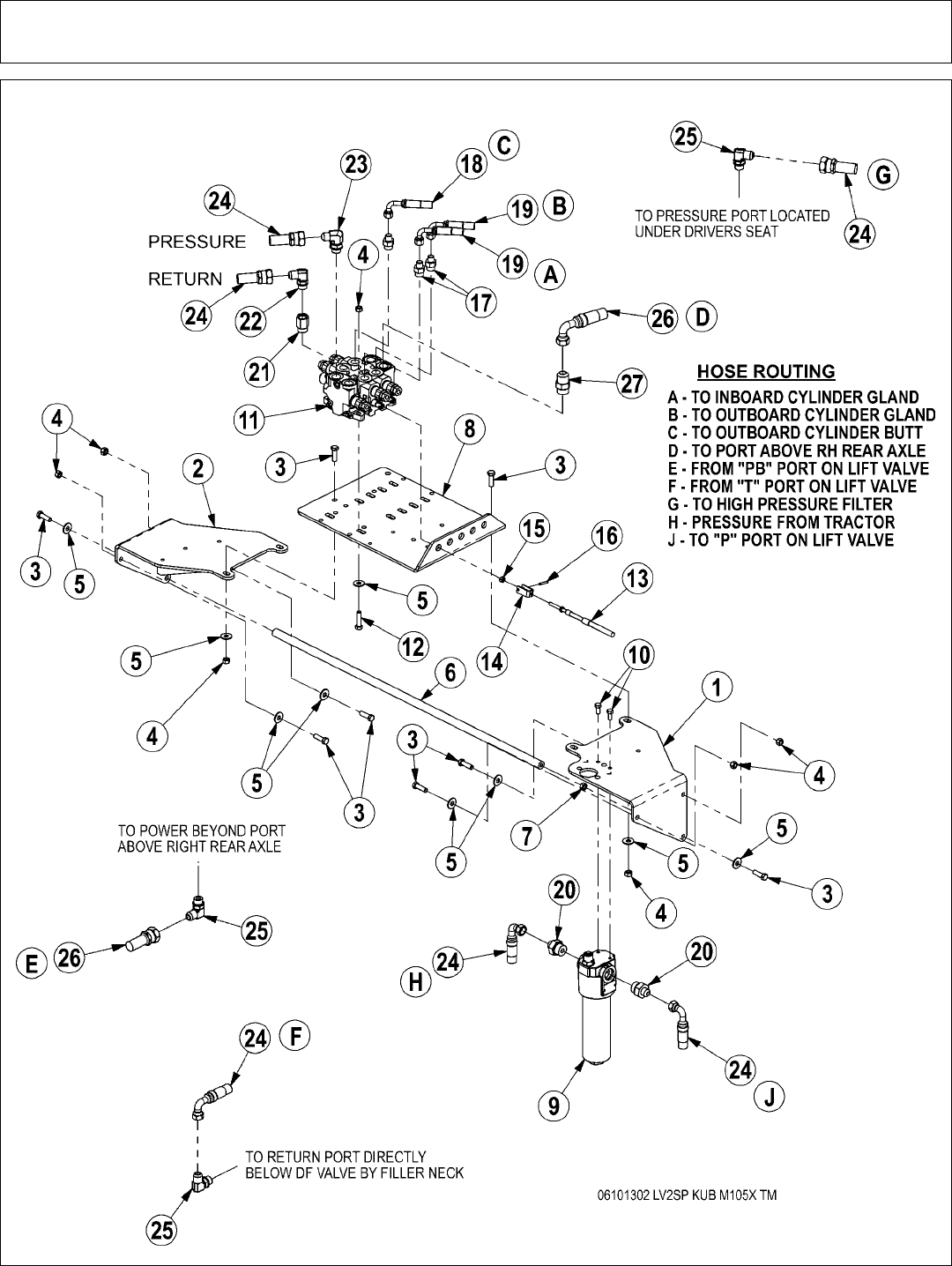
Parts Section 5-12
2SP HUSCO LIFT VALVE - COMBO
4-27-06

Parts Section 5-13
2SP HUSCO LIFT VALVE - COMBO
ITEM PART NO. QTY. DESCRIPTION
1 06340023 1 VALVE MNT,RH,KUB,M105X
2 06340024 1 VALVE MNT,LH,KUB,M105X
3 21631 10 CAPSCREW,3/8 X 1-1/4 NC
4 21627 12 NYLOCK NUT,3/8 NC
5 22016 14 FLATWASHER,3/8
6 06430044 1 BRACE,VLV MNT,KUB
7 21625 1 HEX NUT,3/8 NC
8 34622 1 PLATE,VALVE,REAR MNT
9 06505029 1 FILTER,HP,3/4SAE,11MIC,VIS IND
10 21579 2 CAPSCREW,5/16 X 3/4 NC
11 30801 1 VALVE,2SP,HSC,S/A,D/A,W/PB
12 21632 4 CAPSCREW,3/8 X 1-1/2 NC
13 34623 2 CBL,CNTRL,122
14 6T4411 2 CLEVIS,CBL CTRL,3/16
15 21500 2 HEX NUT,1/4 NF
16 6T3017 2 ROLLPIN,3/16 X 1
17 33271 3 ADAPTER,1/2 MOR X 3/8 MJ
18 34631 1 HOSE,1/4x126(3/8FJXx3/8FJX90)
19 34632 2 HOSE,1/4x115(3/8FJXx3/8FJX90)
20 33591 2 ADAPTER,3/4MORX1/2MJ
21 32678 1 ADAPTER,5/8ORB x 1/2FOR
22 33382 1 ELBOW,1/2MORB X 1/2MJ X 90
23 33383 1 ELBOW,5/8MORB X 1/2MJ X 90
24 33649 3 HOSE,1/2x50(1/2FJXx1/2FJX90)
25 06503066 3 ELBOW,1/2BSPPx1/2MJ,90
26 33486 1 HOSE,1/2X45(1/2FJX90X1/2FJX)
27 06503036 1 ADAPTER,5/8ORBx5/8MJ
4-27-06
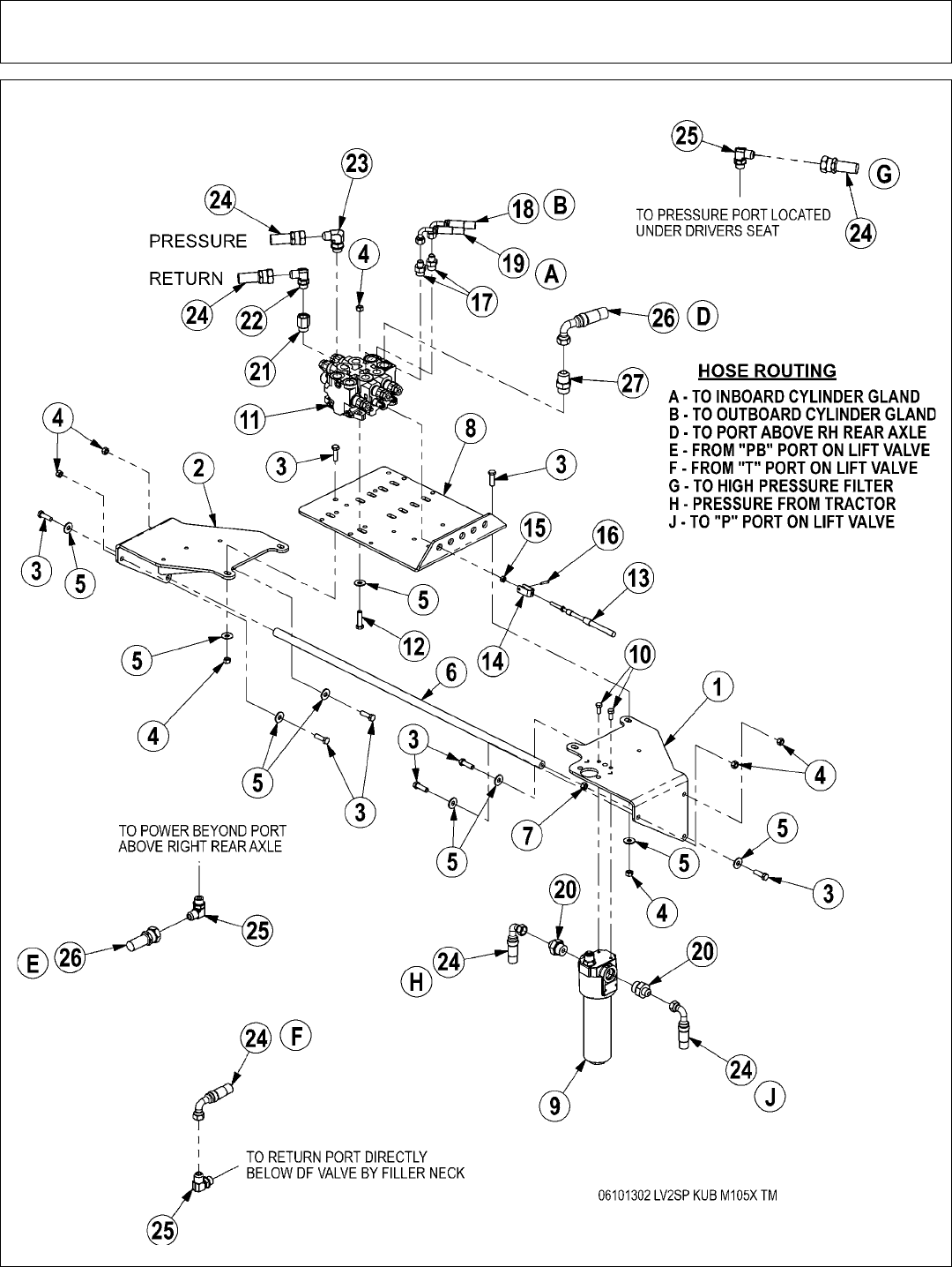
Parts Section 5-14
2SP HUSCO LIFT VALVE - CABLE

Parts Section 5-15
2SP HUSCO LIFT VALVE - CABLE
ITEM PART NO. QTY. DESCRIPTION
1 06340023 1 VALVE MNT,RH,KUB,M105X
2 06340024 1 VALVE MNT,LH,KUB,M105X
3 21631 10 CAPSCREW,3/8 X 1-1/4 NC
4 21627 12 NYLOCK NUT,3/8 NC
5 22016 14 FLATWASHER,3/8
6 06430044 1 BRACE,VLV MNT,KUB
7 21625 1 HEX NUT,3/8 NC
8 34622 1 PLATE,VALVE,REAR MNT
9 06505029 1 FILTER,HP,3/4SAE,11MIC,VIS IND
10 21579 2 CAPSCREW,5/16 X 3/4 NC
11 31752 1 VALVE,2SP,HSC,BLK,2-S/A,PB
12 21632 4 CAPSCREW,3/8 X 1-1/2 NC
13 34623 2 CBL,CNTRL,122
14 6T4411 2 CLEVIS,CBL CTRL,3/16
15 21500 2 HEX NUT,1/4 NF
16 6T3017 2 ROLLPIN,3/16 X 1
17 33271 2 ADAPTER,1/2 MOR X 3/8 MJ
18 34631 1 HOSE,1/4x126(3/8FJXx3/8FJX90)
19 34632 1 HOSE,1/4x115(3/8FJXx3/8FJX90)
20 33591 2 ADAPTER,3/4MORX1/2MJ
21 32678 1 ADAPTER,5/8ORB x 1/2FOR
22 33382 1 ELBOW,1/2MORB X 1/2MJ X 90
23 33383 1 ELBOW,5/8MORB X 1/2MJ X 90
24 33649 3 HOSE,1/2x50(1/2FJXx1/2FJX90)
25 06503066 3 ELBOW,1/2BSPPx1/2MJ,90
26 33486 1 HOSE,1/2X45(1/2FJX90X1/2FJX)
27 06503036 1 ADAPTER,5/8ORBx5/8MJ
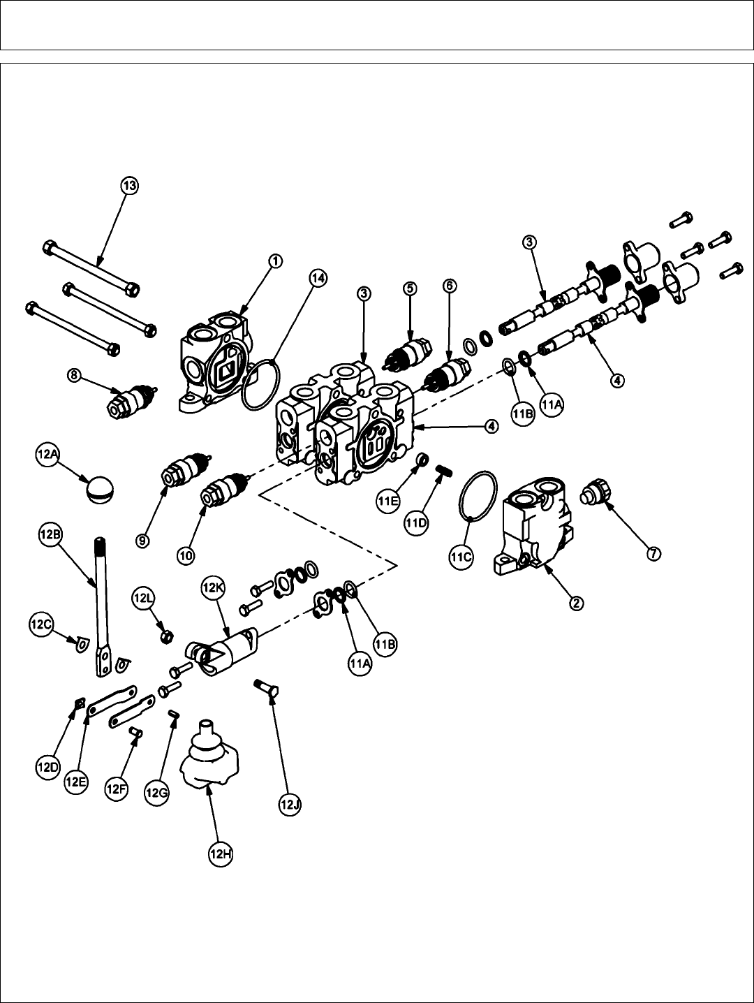
Parts Section 5-16
2SP HUSCO VALVE - POWER BEYOND (30801)

Parts Section 5-17
2SP HUSCO VALVE - POWER BEYOND (30801)
ITEM PART NO. QTY DESCRIPTION
1 TB1017S 1 INLET END COVER
2 TB1702 1 END COVER, POWER BEYOND
3 TB1017P 1 VALVE SECTION (SINGLE ACTING, SPRING DETENT)
4 06502091 1 VALVE SECTION (DOUBLE ACTING, CENTER SPRING)
(NO AUX VALVE PORTS)
5 N/A - N/A
6 N/A - N/A
7 TB1017M 1 SHUT-OFF PLUG
8 TB1017E 1 RELIEF VALVE, 2250 PSI
9 TB1017M 1 SHUT-OFF PLUG
10 TB1017M 1 SHUT-OFF PLUG
11 TB1017A 2 VALVE SEAL KIT (FOR ONE SECTION)
11A 2 WIPER
11B 2 O-RING SMALL
11C 1 O-RING LARGE
11D 1 SPRING
11E 1 PUCKET
12 TB1017L 2 LEVER KIT (FOR ONE SECTION)
12A 1 LEVER KNOB
12B 1 LEVER
12C 2 LEVER WASHER
12D 1 LEVER CLIP
12E 2 LINKAGE
12F 1 LEVER PIN
12G 1 ROLL PIN
12H 1 LEVER BOOT
12J 1 LEVER BOLT
12K 1 LEVER DUST COVER
12L 1 LEVER NUT
13 TB1017X 1 TIE ROD KIT
14 24214 1 O-RING, LARGE

Parts Section 5-18
2SP HUSCO VALVE - POWER BEYOND (31752)

Parts Section 5-19
2SP HUSCO VALVE - POWER BEYOND (31752)
ITEM PART NO. QTY DESCRIPTION
1 TB1017S 1 INLET END COVER
2 TB1702 1 END COVER, POWER BEYOND
3 TB1017P 1 VALVE SECTION (SINGLE ACTING, SPRING DETENT)
4 TB1017P 1 VALVE SECTION (SINGLE ACTING, SPRING DETENT)
5 N/A - N/A
6 N/A - N/A
7 TB1017M 1 SHUT-OFF PLUG
8 TB1017E 1 RELIEF VALVE, 2250 PSI
9 TB1017M 1 SHUT-OFF PLUG
10 TB1017M 1 SHUT-OFF PLUG
11 TB1017A 2 VALVE SEAL KIT (FOR ONE SECTION)
11A 2 WIPER
11B 2 O-RING SMALL
11C 1 O-RING LARGE
11D 1 SPRING
11E 1 PUCKET
12 TB1017L 2 LEVER KIT (FOR ONE SECTION)
12A 1 LEVER KNOB
12B 1 LEVER
12C 2 LEVER WASHER
12D 1 LEVER CLIP
12E 2 LINKAGE
12F 1 LEVER PIN
12G 1 ROLL PIN
12H 1 LEVER BOOT
12J 1 LEVER BOLT
12K 1 LEVER DUST COVER
12L 1 LEVER NUT
13 TB1017X 1 TIE ROD KIT
14 24214 1 O-RING, LARGE
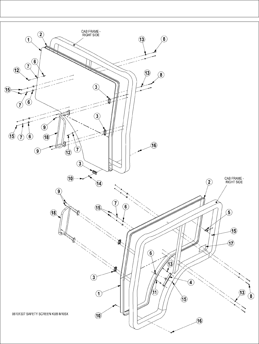
Parts Section 5-20
SAFETY SCREEN - KUBOTA M105X

Parts Section 5-21
SAFETY SCREEN - KUBOTA M105X
ITEM PART NO. QTY. DESCRIPTION
1 06490023 1 POLYCARB,FRMD,KUB,M105X,RH
2 31965 20’ TRIM SEAL,3/8 CLIP X 3/4 OD
3 06520040 3 BRKT,JD,POLY,RETAIN
4 06410391 1 MNT,POLY,KUB
5 06410392 1 MNT,SM,POLY,KUB
6 06537000 6 WASHER,NEOPRENE,.25x1x.38
7 06537001 6 WASHER,RUBBERIZED,.25,CONICAL
8 21538 4 CAPSCREW,1/4 X 3 NC
9 27506 4 CAPSCREW,6MMX20MM(1.0 PITCH)
10 21580 1 CAPSCREW,5/16 X 1 NC
11 06530511 2 CAPSCREW,6MMX25MM(1.0 PITCH)
12 21532 2 CAPSCREW,1/4 X 1-1/2 NC
13 22014 6 FLATWASHER,1/4
14 22015 1 FLATWASHER,5/16
15 21527 6 NYLOCK NUT,1/4 NC
16 21577 1 NYLOCK NUT,5/16 NC
17 22645 1 DECAL,POLYCARBONATE WINDOW INS
18 * 1 EXISTING - RIGHT HAND RAIL
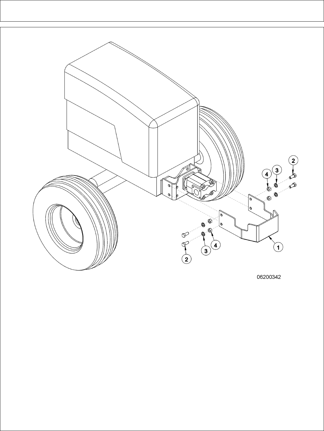
Parts Section 5-22
OPTIONAL PUMP GUARD KIT
ITEM PART NO. QTY. DESCRIPTION
1 32430 1 UNIVERSAL PUMP GUARD
2 21831 4 CAPSCREW - 3/4 X 1 3/4
3 21993 4 LOCKWASHER - 3/4
4 21825 4 HEX NUT - 3/4
11-20-01
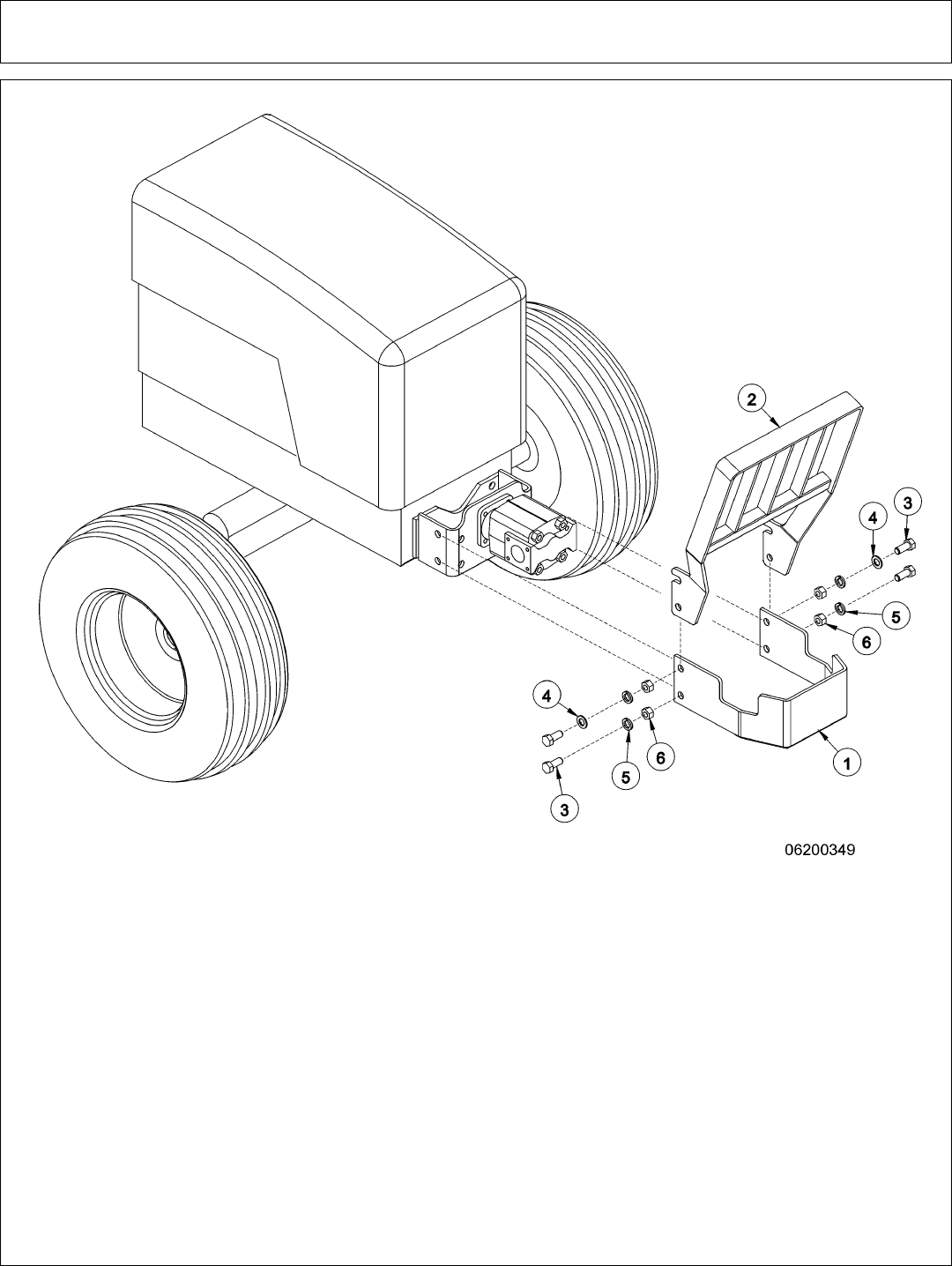
Parts Section 5-23
OPTIONAL PUMP AND GRILL GUARD KIT
ITEM PART NO. QTY. DESCRIPTION
1 32430 1 UNIVERSAL PUMP GUARD
2 32737 1 UNIVERSAL GRILL GUARD
3 21833 4 CAPSCREW - 3/4 X 2 1/4
4 22021 2 FLATWASHER - 3/4
5 21993 4 LOCKWASHER - 3/4
6 21825 4 HEX NUT - 3/4
11-20-01
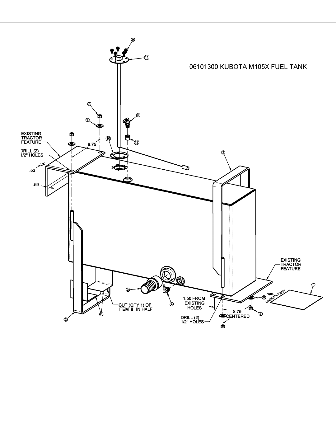
Parts Section 5-24
ITEM PART NO. QTY. DESCRIPTION
1 06370048 1 FUEL TANK,RH,KUB,M105X
2 06370049 2 TANK STRAP,KUB,M105X
3 06503061 1 ADAPTER,1 1/4NPTx1 1/4BARB
4 06503063 1 ELBOW,3/8NPTx3/8BARB
5 06503092 1 ELBOW,1/4NPTx1/4BARB
6 22016 4 FLATWASHER,3/8
7 21627 4 NYLOCK NUT,3/8 NC
8 6T3200 2 SPLIT HOSE
9 * 5 EXISTING HARDWARE
10 * 1 EXISTING HARDWARE
11 * 1 EXISTING HARDWARE
12 06503091 1 ADAPTER
FUEL TANK - KUBOTA M105X
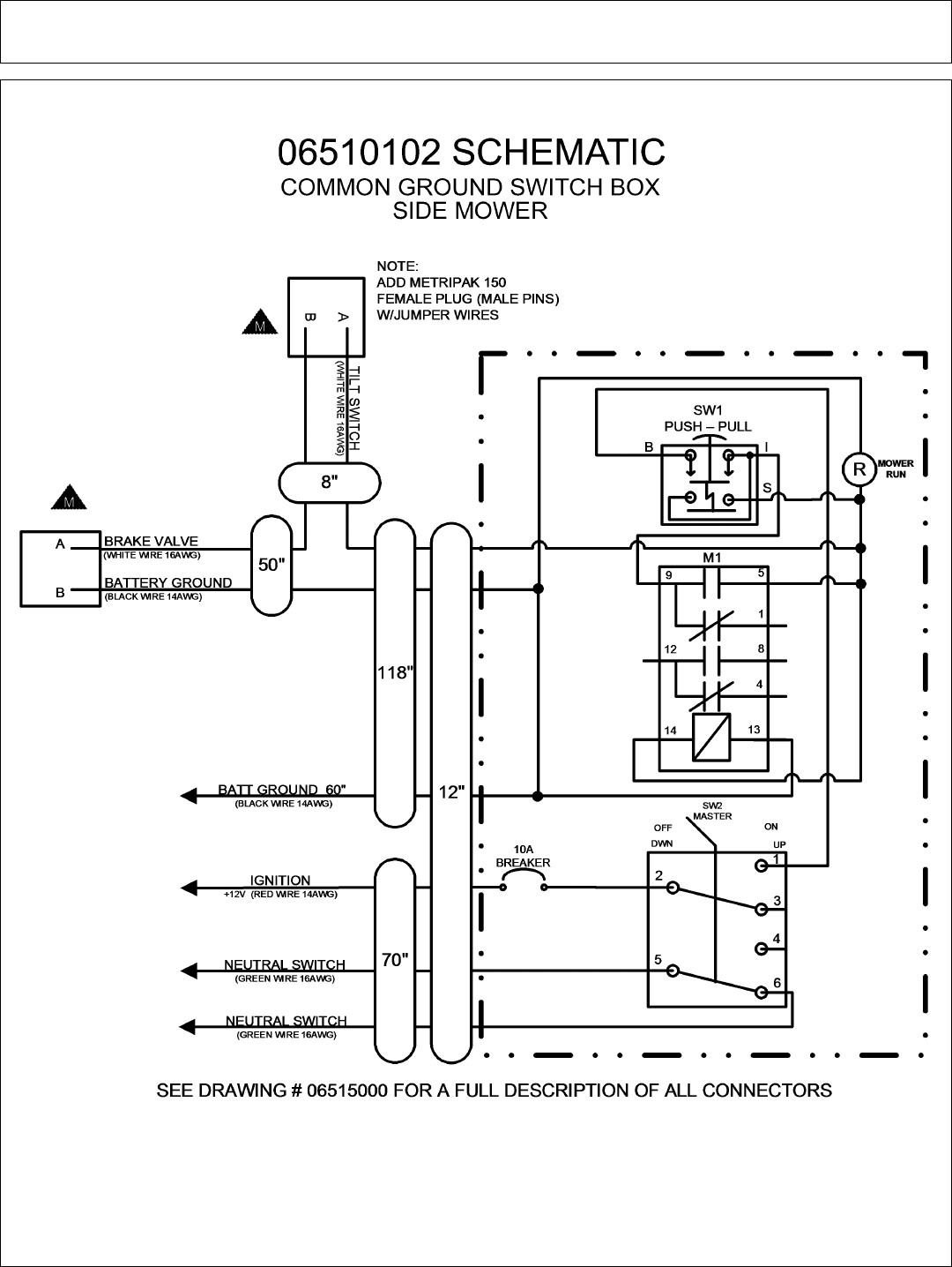
Parts Section 5-25
SWITCH BOX SCHEMATIC
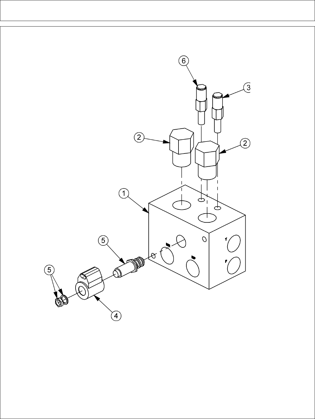
Parts Section 5-26
SOLENOID BRAKE VAVLE ASSEMBLY
ITEM PART NO. QTY. DESCRIPTION
1 34092 1 BRAKE VALVE, BLANK
2 34095 1 RELIEF VALVE, 3000 PSI
3 34094 2 LOGIC ELEMENT
4 06510095 1 METRI PAK COIL
5 34093 1 CARTRIDGE, 2 POSITION, 3 WAY (WITH NUT & WASHER)
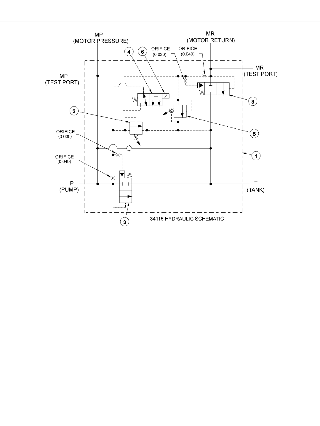
Parts Section 5-27
SOLENOID BRAKE VALVE HYDRAULIC SCHEMATIC
BRAKE VALVE TROUBLESHOOTING
FAILURE MODE: CHECK STEPS
- MOWER WILL NOT START - system pressure is low
(engine not lugging). 1 thru 6
- MOWER WILL NOT START - system pressure is high
(engine lugging). “MR” port will be high pressure. 7
- MOWER WILL NOT ROTATE AT FULL SPEED - limited power. 3 thru 5
- MOWER BLADE WILL NOT STOP - blade will not stop in proper time. 7 thru 9
CORRECTIVE STEPS:
1. Check for voltage at solenoid (item 6), voltage must be between 10.2 volts and 13.8 volts.
2. Remove, inspect solenoid and cartridge (items 4, 6) for wear or contamination.
3. Remove, inspect logic elements near “P” port (item 3) for wear or contamination.
4. Remove, inspect 3000 psi relief valve (item 2) for wear or contamination.
5. Remove and inspect orifices near “P” port for contamination.
6. Remove “P” port hose and fitting, visually inspect for contamination, check ball for movement.
7. Remove and inspect orifices near “MR” port for contamination.
8. Remove, inspect 2600 psi relief valve (item 5) for wear of contamination.
9. Remove, inpect logic element near “MR” port (item 3) for wear or contamination.
7-25-02

Parts Section 5-28

Side Rotary Common Section 6 - 1
SIDE ROTARYCOMMON SECTION
COMMON
PARTS
SECTION

Side Rotary Common Section 6 - 2
TABLE OF CONTENTS
SECTION ASSEMBLY PAGE
CABLE LIFT ASSEMBLY 6-4
COMBO DRAFT BEAM 6-6
60” SIDE CABLE ROTARY MOWER ASSEMBLY 6-8
72” SIDE CABLE ROTARY MOWER ASSEMBLY 6-10
60” SIDE COMBO RTRY MOWER ASSEMBLY 6-12
60” SIDE ROTARY MOWER 6-14
60” SPINDLE AND SPACER 6-16
72” SIDE COMBO ROTARY MOWER ASSY 6-18
TM72” MOTOR ASSEMBLY 6-20
CHAIN GUARDS 6-22
SIDE ROTARY CASTER WHEEL ASSEMBLY 6-24
RESERVOIR TANK FILTER ASSEMBLY 6-26
MOWER SPINDLE ASSEMBLIES 6-28
HYDRAULIC LIFT CYLINDER 6-32
ROTARY KNIVES AND DISKS 6-34
CASTER WHEEL ASSEMBLY 6-35
ROTARY MOTORS 6-36
FRONT HYDRAULIC PUMP 6-38
TSR MOTOR 6-38
COOLER ASSEMBLY 6-40
2 SPOOL HUSCO VALVES 6-42
SOLENOID VALVE ASSEMBLY 6-54
SOLENOID BRAKE VALVE ASSEMBLY 6-55
BRAKE VALVE ASSEMBLY W/METRI PAK 6-56
SOLENOID BRAKE VALVE SCHEMATIC 6-57
TRAVEL LOCK LIFT BEAM 6-58
SIDE MOWER TRAVEL LOCK (COMBO) 6-59
SWITCHBOX SCHEMATIC 6-60

Side Rotary Common Section 6 - 3
The following instructions are offered to help eliminate needless delay and error in
processing purchase orders for the equipment in this manual.
1. The Parts Section is prepared in logical sequence and grouping of parts that
belong to the basic machine featured in this manual. Part Numbers and
Descriptions are given to help locate the parts and quantities required.
2. The Purchase Order must indicate the Name and Address of the person or
organization ordering the parts, who should be charged, and if possible, the serial
number of the machine for which the parts are being ordered.
3. The purchase order must clearly list the quantity of each part, the complete
and correct part number, and the basic name of the part.
4. The manufacturer reserves the right to substitute parts where applicable.
5. Some parts may be unlisted items which are special production items not
normally stocked and are subject to special handling. Request a quotation for such
parts before sending a purchase order.
6. The manufacturer reserves the right to change prices without prior notice.
NOTE: When ordering replacement decals, refer to the part numbers and
descriptions listed in the safety section in the front of this manual.
For maximum safety and to guarantee optimum product reliability,
always use genuine Tiger replacement parts. The use of inferior
replacement parts may cause premature or catastrophic failure
which could result in serious injury or death.
Direct any questions regarding parts to:
Tiger Corporation
3301 N. Louise Ave.
Sioux Falls, SD 57107
1-800-843-6849
1-605-336-7900
PARTS ORDERING GUIDE
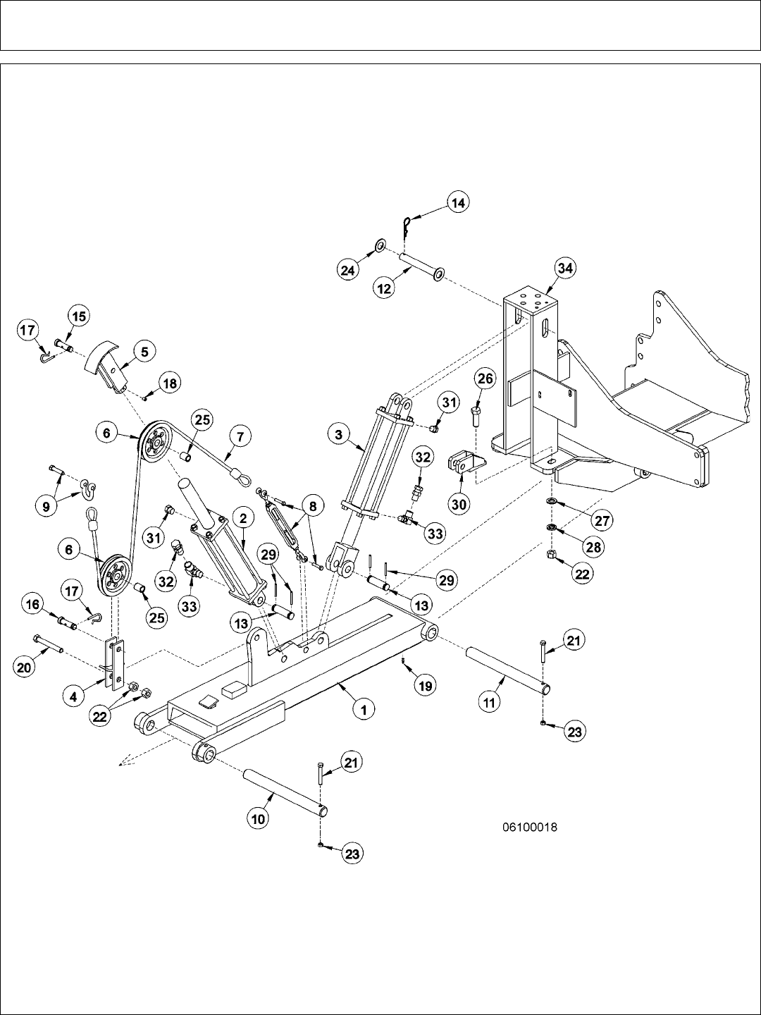
Side Rotary Common Section 6 - 4
CABLE LIFT ASSEMBLY
3-22-02

Side Rotary Common Section 6 - 5
CABLE LIFT ASSEMBLY
ITEM PART NO. QTY. DESCRIPTION
1 6T0103A 1 DRAFT BEAM (STD 25 LB, 45 3/8”)
6T0103E OPT. DRAFT BEAM (EXTENDED 6” 4WD)
6T0103L OPT. DRAFT BEAM (EXTENDED 15”)
6T0105 OPT. DRAFT BEAM (STD WITH TRAVEL LOCK)
6T0108 OPT. DRAFT BEAM (30 LB CHANNEL, 45 3/8”)
2 6T0150 1 CYLINDER 3” X 18”
3 6T0151R 1 CYLINDER 3” X 10”
4 6T0100 1 LOWER SHEAVE BRACKET
5 6T0101 1 UPPER SHEAVE BRACKET
6 33768 2 SHEAVE
7 6T0110 1 LIFT CABLE (STD 1/2” X 87 1/2”)
6T0110E OPT. LIFT CABLE (EXTENDED 6” 4WD)
6T0110L OPT. LIFT CABLE (EXTENDED 15”)
8 6T0115 1 TURN BUCKLE
9 6T0112 1 SHACKLE WITH PIN
10 6T2999 1 OUTER DRAFT BEAM PIN 1 1/2” X 14 1/2”
11 6T3001 1 INNER DRAFT BEAM PIN 1 1/2” X 15 3/4”
12 6T3005 1 PIN ,1” W/ CAP
13 TB1033 2 CLEVIS PIN 1” X 4”
14 6T3004 1 R - CLIP 3/16”
15 6T3010 1 UPPER SHEAVE PIN WITH ZERK 3/4” X 3”
16 6T3009 1 LOWER SHEAVE PIN WITH ZERK 3/4” X 2 1/2”
17 6T3020 2 R - CLIP 5/32”
18 6T2272 1 SET SCREW 3/8” X 1/2”
19 6T3211 1 GREASE ZERK 1/8” STRAIGHT
20 21836 1 CAPSCREW 3/4” X 3”
21 21688 2 CAPSCREW 7/16” X 3 1/4”
22 21825 2 HEX NUT 3/4”
23 21677 2 NYLOCK NUT 7/16”
24 22023 1 FLAT WASHER 1”
25 6T0104N 2 SHEAVE PIN BUSHING 1” OD X 3/4” ID
26 21833 1 CAPSCREW 3/4” X 2 1/4”
27 22021 1 FLAT WASHER 3/4”
28 21993 1 LOCK WASHER 3/4”
29 06537021 4 ROLL PIN
30 6T0106 1 TRAVEL LOCK BRACKET
31 6T4258 1 BREATHER 1/2”
32 34396 2 RESTRICTOR
33 34244 2 ELBOW FITTING 1/2”
34 * REF. MAIN FRAME REFER TO TRACTOR PARTS SECTION
3-22-02
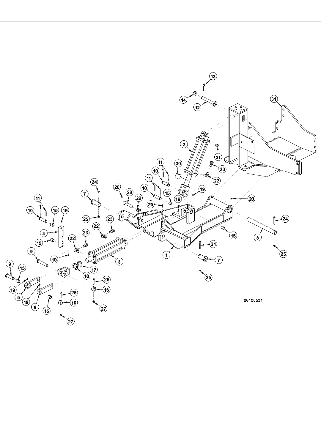
Side Rotary Common Section 6 - 6
COMBO DRAFT BEAM
3-22-02

Side Rotary Common Section 6 - 7
COMBO DRAFT BEAM
ITEM PART NO. QTY. DESCRIPTION
1 06350001 1 COMBO DRAFT BEAM - STD DTY ROTARY
31063 OPT. COMBO DRAFT BEAM - HVY DTY ROTARY
2 6T0151R 1 HYD. CYLINDER 3” X 10”
3 32215 1 HYD. CYLINDER 3” X 12” - STD DTY
25343 REF HYD. CYLINDER 3” X 12” - HVY DTY
4 TF4500A 1 PIVOT ARM
5 TF4507B 1 RIGHT LINKAGE ARM
6 TF4506B 1 LEFT LINKAGE ARM
7 30126B 2 PIN, HEAD PIVOT - STD DTY
TF4514A REF PIN, HEAD PIVOT - HVY DTY
8 6T3001 1 PIN, BEAM PIVOT
9 TF4519 2 PIN, LINKAGE
10 TB1033 3 PIN, CLEVIS
11 06537021 6 ROLLPIN
12 6T3005 1 PIN,1” W/ CAP
13 6T3004 1 R-CLIP HAIRPIN
14 6T2614 1 FLATWASHER 1”
15 TB3010 8 BUSHING 1”
16 22847 2 BOSS, LINKAGE PIN
17 22076 1 SPACER, HYD. CYLINDER 1/4”
18 22077 1 SPACER, HYD. CYLINDER 5/16”
19 6T3207 6 GREASE ZERK 1/4”
20 6T3211 3 GREASE ZERK 1/8”
21 6T4258 1 BREATHER 1/2”
22 34244 3 ELBOW FITTING 1/2”
23 34396 3 SWIVEL RESTRICTOR
24 21688 3 CAPSCREW 7/16” X 3 1/4”
25 21675 3 HEX NUT 7/16”
26 21635 2 CAPSCREW 3/8” X 2 1/4”
27 21625 2 HEX NUT 3/8”
28 21831 1 CAPSCREW 3/4” X 1 3/4”
29 21825 1 HEX NUT 3/4”
30 06700095 1 CYLINDER SPACER W/SET SCREW
31 * REF REFER TO MAIN FRAME
NOTES:
1. ITEM 30 IS USED ON THE GLAND END OF ITEM 2 (AS NEEDED)
2. ORIENTATION OF ITEM 4 IS CRITICAL
3-22-02
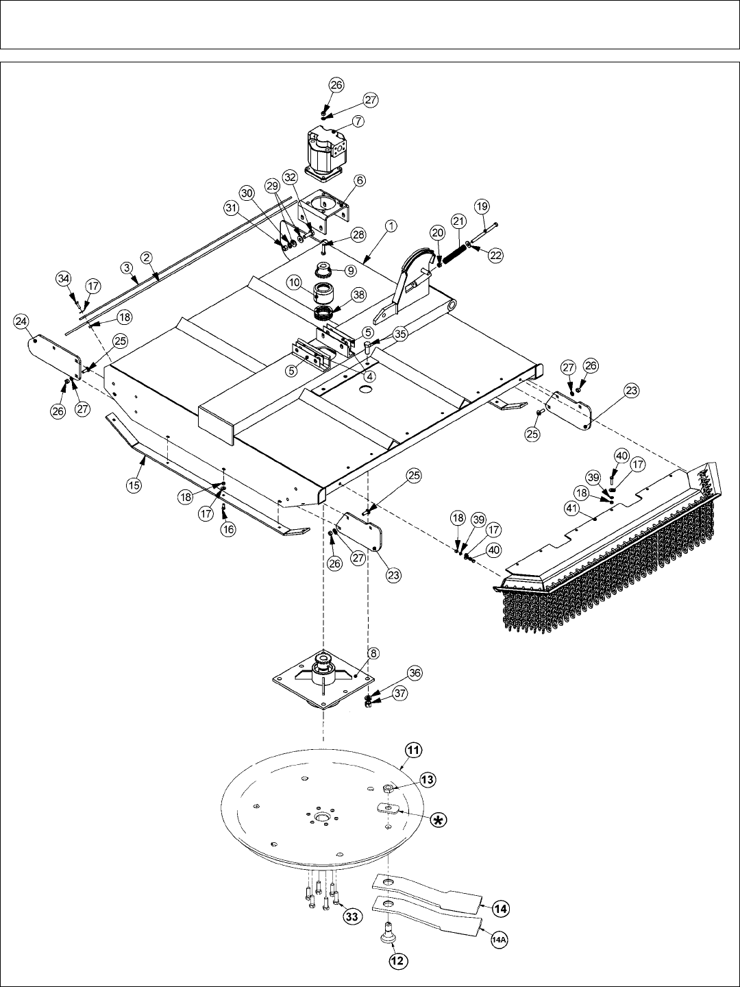
Side Rotary Common Section 6 - 8
60” SIDE CABLE ROTARY MOWER

Side Rotary Common Section 6 - 9
60” SIDE CABLE ROTARY MOWER
ITEM PART NO. QTY. DESCRIPTION
1 32099 1 RTRY, 60" WELDMENT, 1/4" DECK
21225B 1 RTRY, 72” WELDMENT, 1/4” DECK
2 22592 1 FLAP, DEFLECTOR, TM60
3 6T0823 1 BAR, FLAP, TM60
4 6T0822 2 SHIM, MOTOR MOUNT, 14GA. (AS NEEDED)
5 6T0822A 2 SHIM, MOTOR MOUNT, 18 GA. (AS NEEDED)
6 6T1001 1 BRKT, MOTOR MTG, 60"SIDE RTRY
706504011 1 CURRENT MOTOR,(M365-2 1/4" GEAR)
23172 1 ORIGINAL MOTOR,(M365-2 1/4" GEAR)
8 6T1024H5 1 SPINDLE ASSY,CPLT,HD,5/8 HOLES
9 21223 1 SPROKET, 1-1/4" BORE
10 6T1033 1 COVER, COUPLING
11 SEE NEW ROTARY KNIVES AND DISKS PAGE
12 SEE NEW ROTARY KNIVES AND DISKS PAGE
13 SEE NEW ROTARY KNIVES AND DISKS PAGE
14 SEE NEW ROTARY KNIVES AND DISKS PAGE
14A SEE NEW ROTARY KNIVES AND DISKS PAGE
* SEE NEW ROTARY KNIVES AND DISKS PAGE
15 6T0820H 2 SKID SHOE, TM60, HEAVY DUTY
16 6T2270 10 PLOW BOLT,3/8" X 1" NC
17 22016 29 FLATWASHER,3/8"
18 21625 29 HEX NUT,3/8",NC
19 21745 1 CAPSCREW, 1/2 x 7,NC
20 21727 1 NYLOCK NUT, 1/2
21 27005 1 SPRING, PUSHOFF, SIDE RTRY
22 22018 1 FLATWASHER,1/2",WIDE
23 33655 2 PLATE,GAURD,SAFETY,FRONT, RTRY
24 33656 1 PLATE,GUARD,SAFETY,REAR,RTRY
25 6T2267 9 CARRIAGE BOLT, 1/2" x 2" NF, GR8
26 21725 13 HEX NUT, 1/2" NC
27 21990 13 LOCKWASHER, 1/2"
28 21733 4 CAPSCREW, 1/2 x 2,NC
29 25270 8 FLATWASHER,5/8", GR 8
30 21992 10 LOCKWASHER, 5/8
31 21775 4 HEX NUT, 5/8
32 21783 4 CAPSCREW, 5/8 x 2,NC
33 6T2290 6 CAPSCREW,5/8x2,NF GR 8
34 21631 11 CAPSCREW, 3/8" x 1-1/4" NC
35 6T2277 6 CAPSCREW, 3/4" x 2" NF
36 21993 6 LOCKWASHER,3/4",GR 8
37 6T2413 6 HEX NUT,3/4,NF,GR 8
38 6T1029 1 CHAIN, COUPLING
39 21988 8 LOCKWASHER, 3/8"
40 21632 8 CAPSCREW,3/8" X 1-1/2" NC
41 31773 1 GAURD,CHAIN,FRONT,SR60
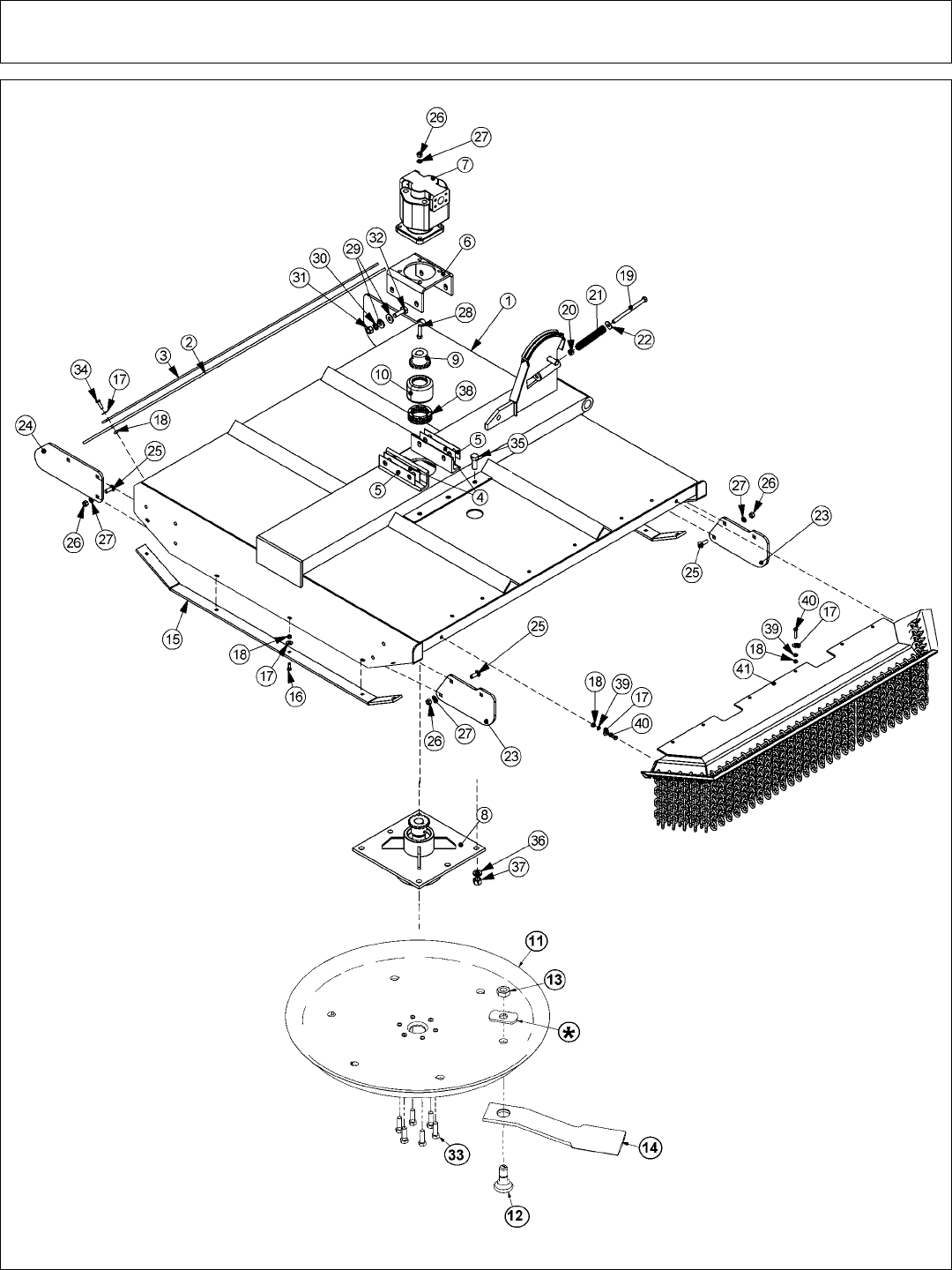
Side Rotary Common Section 6 - 10
72” SIDE CABLE ROTARY MOWER

Side Rotary Common Section 6 - 11
72” SIDE CABLE ROTARY MOWER
ITEM PART NO. QTY. DESCRIPTION
1 21225B 1 RTRY, 72” WELDMENT, 1/4” DECK
2 21295B 1 FLAP, DEFLECTOR, TM72
3 21242A 1 BAR, FLAP, TM72
4 6T0822 2 SHIM, MOTOR MOUNT, 14GA. (AS NEEDED)
5 6T0822A 2 SHIM, MOTOR MOUNT, 18 GA. (AS NEEDED)
6 6T1001 1 BRKT, MOTOR MTG, 60"SIDE RTRY
706504018 1 CURRENT MOTOR,(M365-2 1/2" GEAR)
21222 1 ORIGINAL MOTOR,(M365-2 1/2" GEAR)
8 6T1024H5 1 SPINDLE ASSY,CPLT,HD,5/8 HOLES
9 21223 1 SPROKET, 1-1/4" BORE
10 6T1033 1 COVER, COUPLING
11 SEE NEW ROTARY KNIVES AND DISKS PAGE
12 SEE NEW ROTARY KNIVES AND DISKS PAGE
13 SEE NEW ROTARY KNIVES AND DISKS PAGE
14 SEE NEW ROTARY KNIVES AND DISKS PAGE
* SEE NEW ROTARY KNIVES AND DISKS PAGE
15 21248 2 SKID SHOE, TM72
16 6T2270 10 PLOW BOLT,3/8" X 1" NC
17 22016 29 FLATWASHER,3/8"
18 21625 29 HEX NUT,3/8",NC
19 21745 1 CAPSCREW, 1/2 x 7,NC
20 21727 1 NYLOCK NUT, 1/2
21 27005 1 SPRING, PUSHOFF, SIDE RTRY
22 22018 1 FLATWASHER,1/2",WIDE
23 33655 2 PLATE,GAURD,SAFETY,FRONT, RTRY
24 33656 1 PLATE,GUARD,SAFETY,REAR,RTRY
25 6T2267 9 CARRIAGE BOLT, 1/2" x 2" NF, GR8
26 21725 13 HEX NUT, 1/2" NC
27 21990 13 LOCKWASHER, 1/2"
28 21733 4 CAPSCREW, 1/2 x 2,NC
29 25270 8 FLATWASHER,5/8", GR 8
30 21992 10 LOCKWASHER, 5/8
31 21775 4 HEX NUT, 5/8
32 21783 4 CAPSCREW, 5/8 x 2,NC
33 6T2290 6 CAPSCREW,5/8x2,NF GR 8
34 21631 11 CAPSCREW, 3/8" x 1-1/4" NC
35 6T2277 6 CAPSCREW, 3/4" x 2" NF
36 21993 6 LOCKWASHER,3/4",GR 8
37 6T2413 6 HEX NUT,3/4,NF,GR 8
38 6T1029 1 CHAIN, COUPLING
39 21988 8 LOCKWASHER, 3/8"
40 21632 8 CAPSCREW,3/8" X 1-1/2" NC
41 31931 1 GAURD,CHAIN,FRONT,SR72
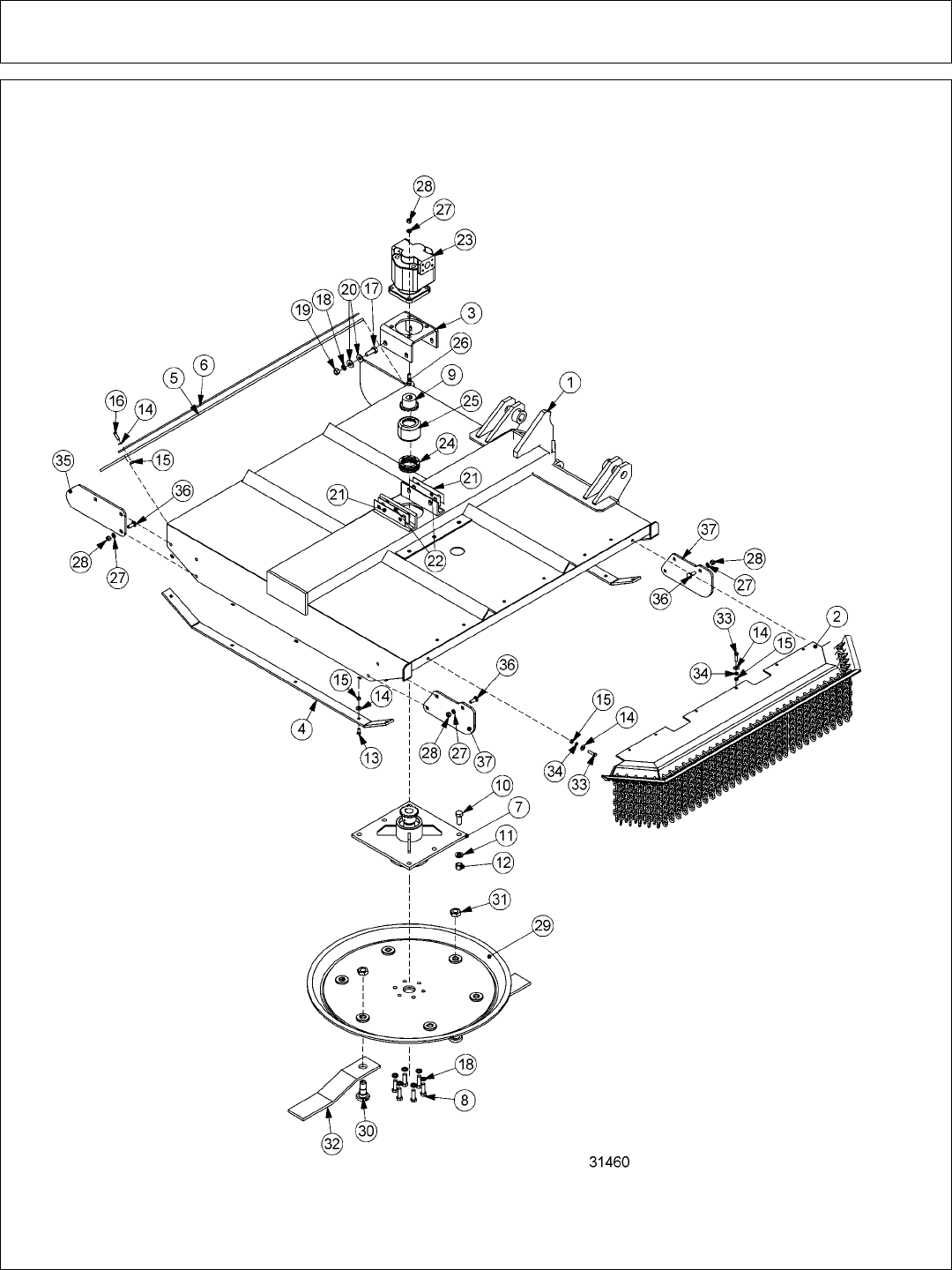
Side Rotary Common Section 6 - 12
60” SIDE COMBO ROTARY MOWER

Side Rotary Common Section 6 - 13
60” SIDE COMBO ROTARY MOWER
ITEM PART NO. QTY. DESCRIPTION
1 32617 1 RTRY, 60" DECK, COMBO - SDT DUTY
30188D 1 RTRY, 60” DECK, COMBO - HEAVY DUTY
2 31773 1 GAURD,CHAIN,FRONT,SR60
3 6T1001 1 BRKT, MOTOR MTG, 60"SIDE RTRY
4 6T0820H 2 SKID SHOE, TM60, HEAVY DUTY
5 22592 1 FLAP, DEFLECTOR, TM60
6 6T0823 1 BAR, FLAP, TM60
7 6T1024H5 1 SPINDLE ASSY,CPLT,HD,5/8 HOLES
8 6T2290 6 CAPSCREW,5/8x2,NF GR 8
9 21223 1 SPROKET, 1-1/4" BORE
10 6T2277 6 CAPSCREW, 3/4" x 2" NF
11 21993 6 LOCKWASHER,3/4",GR 8
12 6T2413 6 HEX NUT,3/4,NF,GR 8
13 6T2270 10 PLOW BOLT,3/8" X 1" NC
14 22016 29 FLATWASHER,3/8"
15 21625 29 HEX NUT,3/8",NC
16 21631 11 CAPSCREW, 3/8" x 1-1/4" NC
17 21783 4 CAPSCREW, 5/8 x 2,NC
18 21992 10 LOCKWASHER, 5/8
19 21775 4 HEX NUT, 5/8
20 25270 8 FLATWASHER,5/8", GR 8
21 6T0822 2 SHIM, MOTOR MOUNT, 14GA. (AS NEEDED)
22 6T0822A 2 SHIM, MOTOR MOUNT, 18 GA. (AS NEEDED)
23 06504011 1 CURRENT MOTOR,(M365-2 1/4" GEAR)
23172 1 ORIGINAL MOTOR,(M365-2 1/4" GEAR)
24 6T1029 1 CHAIN, COUPLING
25 6T1033 1 COVER, COUPLING
26 21733 4 CAPSCREW, 1/2 x 2,NC
27 21990 13 LOCKWASHER, 1/2"
28 21725 13 HEX NUT, 1/2" NC
29 SEE OLD ROTARY KNIVES AND DISKS PAGE
30 SEE OLD ROTARY KNIVES AND DISKS PAGE
31 SEE OLD ROTARY KNIVES AND DISKS PAGE
32 SEE OLD ROTARY KNIVES AND DISKS PAGE
33 21632 8 CAPSCREW,3/8" X 1-1/2" NC
34 21988 8 LOCKWASHER, 3/8"
35 33656 1 PLATE,GUARD,SAFETY,REAR,RTRY
36 6T2267 9 CARRIAGE BOLT, 1/2" x 2" NF, GR8
37 33655 2 PLATE,GAURD,SAFETY,FRONT, RTRY
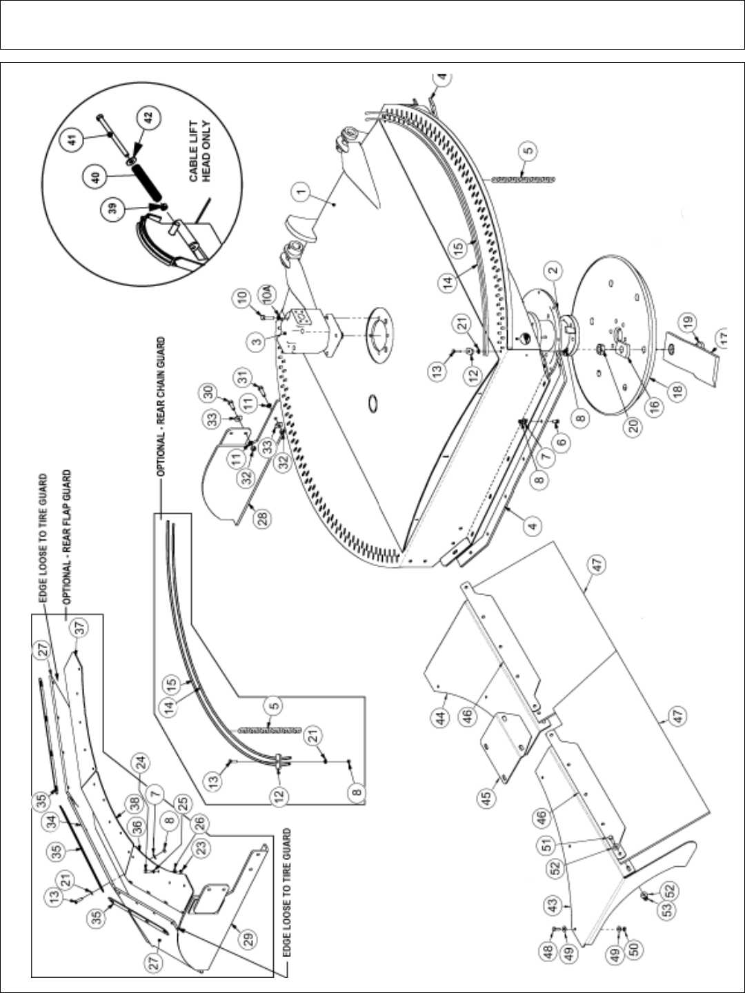
Side Rotary Common Section 6 - 14
60” SIDE ROTARY MOWER
8/26/05

Side Rotary Common Section 6 - 15
60” SIDE ROTARY MOWER
ITEM PART NO. QTY. DESCRIPTION
1 34975 1 HEAVY DUTY GRASSKAT COMBO
06320005 1 STD DUTY GRASSKAT COMBO
06320008 1 HEAVY DUTY GRASSKAT CABLE
2 34980 1 SPINDLE ASSY,TM 60"
306504016 1 CURRENT MOTOR,(M365-1 1/4" 14-SPLINE)
34981 1 ORIGINAL MOTOR,(M365-1 1/4" 14-SPLINE)
4 06410254 2 SKID,OUTBOARD,TM60
5 22992 *156 CHAIN,10 LINK
6 6T2270 14 PLOW BOLT,3/8" X 1" NC
7 22016 *26 FLATWASHER,3/8"
8 21625 *30 HEX NUT,3/8",NC
10 6T1025 4 CAPSCREW, 1/2 x 2,GR 8,NC
10A 06533006 4 FLATWASHER,1/2,SAE,GR 8
11 21990 *8 LOCKWASHER, 1/2"
12 34972 *4 PLATE,CAP,CHAIN
13 21631 *16 CAPSCREW, 3/8 x 1-1/4,NC
14 34974 *2 ROD,CHAIN,INNER,TM60
15 34973 *2 ROD,CHAIN,OUTER,TM60
16 - 20 SEE NEW ROTARY KNIVES AND DISKS PAGE
21 21988 *16 LOCKWASHER, 3/8"
22 6T2290 6 CAPSCREW, 5/8x 1-3/4 (NOT SHOWN)
23 21575 *25 HEX NUT, 5/16”,NC
24 21580 *25 CAPSCREW, 5/16” x 1” NC
25 21987 *25 LOCKWASHER, 5/16”
26 22015 *25 FLATWASHER, 5/16”
27 06520084 *2 ROTARY SIDE FLAP
28 06370029 1 TIRE GUARD, LEFT
29 06370030 *1 TIRE GUARD, RIGHT
30 21731 *4 CAPSCREW, 1/2” x 1-1/2” NC
31 21732 *4 CAPSCREW, 1/2” x 1-3/4” NC
32 21725 *8 HEX NUT, 1/2”,NC
33 22018 *8 FLATWASHER, 1/2”,WIDE
34 06520085 *1 ROTARY CENTER FLAP
35 06400207 *3 ROTARY FLAP STRAP
36 06410207 *1 FLAP MOUNT, RIGHT
37 06410206 *1 FLAP MOUNT, LEFT
38 06410208 *1 FLAP MOUNT, CENTER
CABLE LIFT HEAD ONLY
39 21745 1 NYLOCK NUT, 1/2
40 21727 1 SPRING, PUSHOFF, SIDE RTRY
41 27005 1 CAPSCREW, 1/2 x 7,NC
42 22018 1 FLATWASHER,1/2",WIDE
OPTIONAL SQUARE FLAP
43 06410946 1 MNT,FLAP,LH,EXT,TSR
44 06410947 1 MNT,FLAP,RH,EXT,TSR
45 06410948 1 COVER,FLAP,EXT,TSR
46 06401184 2 STRAP,FLAP,EXT,TSR
47 06520331 2 FLAP,EXT,TSR
48 21580 6 CAPSCREW,5/16 X 1 NC
49 22015 12 FLATWASHER,5/16
50 21575 6 HEX NUT, 5/16,NC
51 21632 10 CAPSCREW,3/8" X 1-1/2" NC
52 22016 20 FLATWASHER,3/8",GR8
53 21625 10 HEX NUT,3/8",NC
8/26/05
* QUANTITY VARIES - REAR CHAIN GUARD & REAR FLAP GUARD IS OPTIONAL.
STANDARD UNIT COMES WITH FRONT CHAINS AND LEFT TIRE GUARD
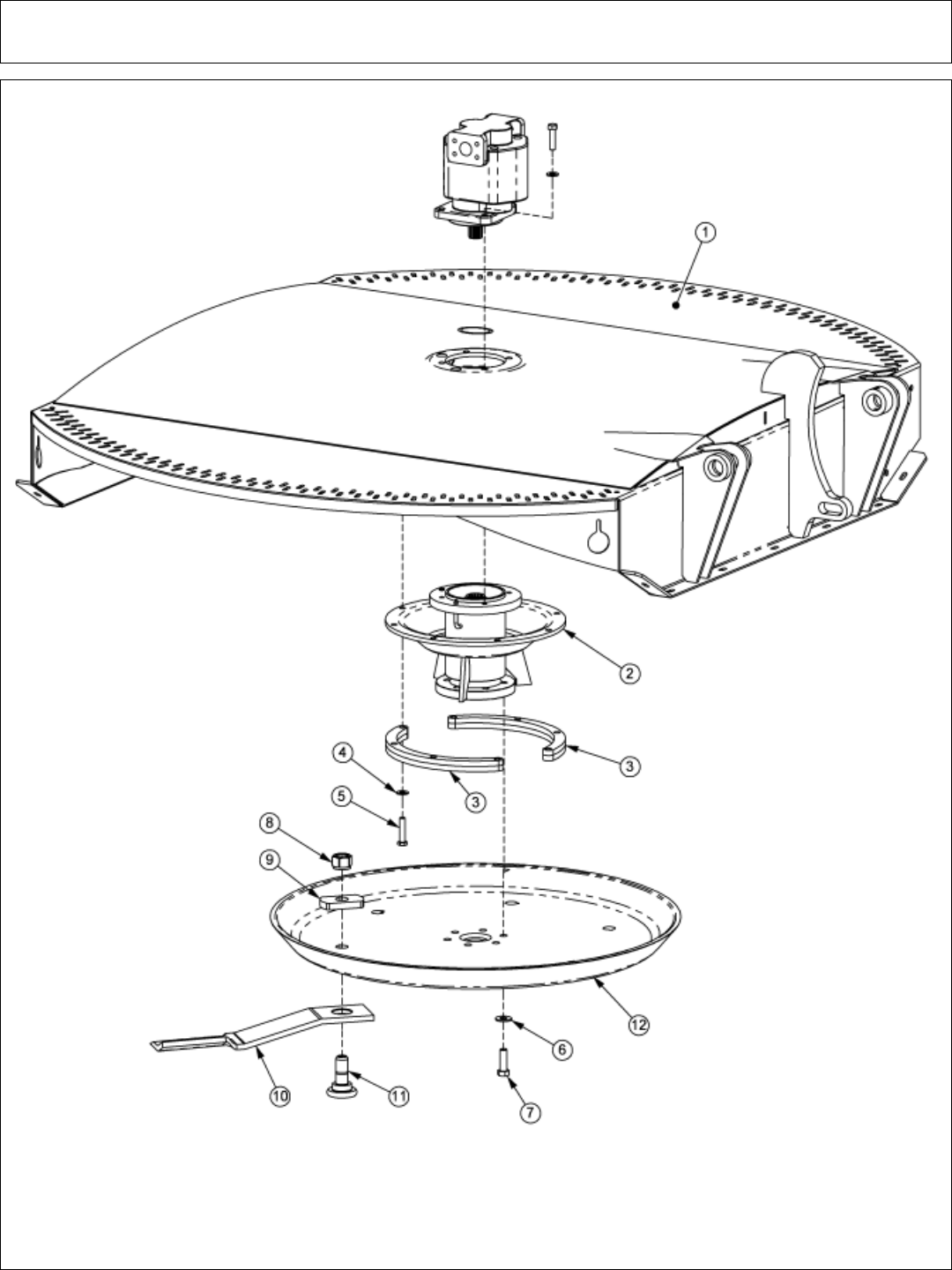
Side Rotary Common Section 6 - 16
60” SIDE ROTARY SPINDLE AND SPACER

Side Rotary Common Section 6 - 17
60” SIDE ROTARY SPINDLE AND SPACER
ITEM PART NO. QTY. DESCRIPTION
1 34975 1 HEAVY DUTY GRASSKAT COMBO
06320005 1 STD DUTY GRASSKAT COMBO
06320008 1 HEAVY DUTY GRASSKAT CABLE
2 34980 1 SPINDLE ASSY,TM 60"
3 06320011 2 SPACER,TSR,SPINDLE
4 06533004 8 FLATWASHER,1/2,SAE,GR 8
5 06530221 8 CAPSCREW, 1/2 x 2-1/4,NF GR 8
6 25270 6 FLATWASHER,5/8,USS,GR8
7 6T2290 6 CAPSCREW,5/8 x 2,NF GR8
8SEE NEW ROTARY KNIVES AND DISKS PAGE
9SEE NEW ROTARY KNIVES AND DISKS PAGE
10 SEE NEW ROTARY KNIVES AND DISKS PAGE
11 SEE NEW ROTARY KNIVES AND DISKS PAGE
12 SEE NEW ROTARY KNIVES AND DISKS PAGE
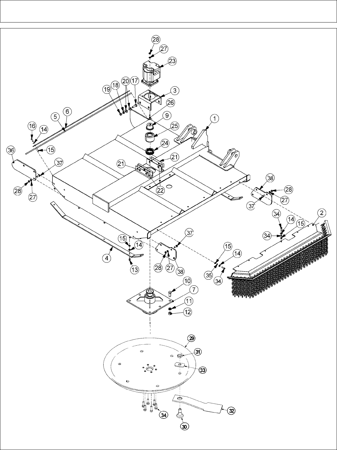
Side Rotary Common Section 6 - 18
72” SIDE COMBO ROTARY MOWER

Side Rotary Common Section 6 - 19
72” SIDE COMBO ROTARY MOWER
ITEM PART NO. QTY. DESCRIPTION
1 34260 1 RTRY, 72" DECK, COMBO - SDT DUTY
31408A 1 RTRY, 72” DECK, COMBO - HEAVY DUTY
2 31931 1 GAURD,CHAIN,FRONT,SR60
3 6T1001 1 BRKT, MOTOR MTG, 60"SIDE RTRY
4 21248 2 SKID SHOE, TM72
5 21295B 1 FLAP, DEFLECTOR, TM72
6 21242A 1 BAR, FLAP, TM72
7 6T1024H5 1 SPINDLE ASSY,CPLT,HD,5/8 HOLES
8 6T2290 6 CAPSCREW,5/8x2,NF GR 8
9 21223 1 SPROKET, 1-1/4" BORE
10 6T2277 6 CAPSCREW, 3/4" x 2" NF
11 21993 6 LOCKWASHER,3/4",GR 8
12 6T2413 6 HEX NUT,3/4,NF,GR 8
13 6T2270 10 PLOW BOLT,3/8" X 1" NC
14 22016 29 FLATWASHER,3/8"
15 21625 29 HEX NUT,3/8",NC
16 21631 11 CAPSCREW, 3/8" x 1-1/4" NC
17 21783 4 CAPSCREW, 5/8 x 2,NC
18 21992 10 LOCKWASHER, 5/8
19 21775 4 HEX NUT, 5/8
20 25270 8 FLATWASHER,5/8", GR 8
21 6T0822 2 SHIM, MOTOR MOUNT, 14GA. (AS NEEDED)
22 6T0822A 2 SHIM, MOTOR MOUNT, 18 GA. (AS NEEDED)
23 06504018 1 CURRENT MOTOR,(M365-2 1/2" GEAR)
21222 1 ORIGINAL MOTOR,(M365-2 1/2" GEAR)
24 6T1029 1 CHAIN, COUPLING
25 6T1033 1 COVER, COUPLING
26 21733 4 CAPSCREW, 1/2 x 2,NC
27 21990 13 LOCKWASHER, 1/2"
28 21725 13 HEX NUT, 1/2" NC
29 SEE NEW ROTARY KNIVES AND DISKS PAGE
30 SEE NEW ROTARY KNIVES AND DISKS PAGE
31 SEE NEW ROTARY KNIVES AND DISKS PAGE
32 SEE NEW ROTARY KNIVES AND DISKS PAGE
33 SEE NEW ROTARY KNIVES AND DISKS PAGE
34 21632 8 CAPSCREW,3/8" X 1-1/2" NC
35 21988 8 LOCKWASHER, 3/8"
36 33656 1 PLATE,GUARD,SAFETY,REAR,RTRY
37 6T2267 9 CARRIAGE BOLT, 1/2" x 2" NF, GR8
38 33655 2 PLATE,GAURD,SAFETY,FRONT, RTRY
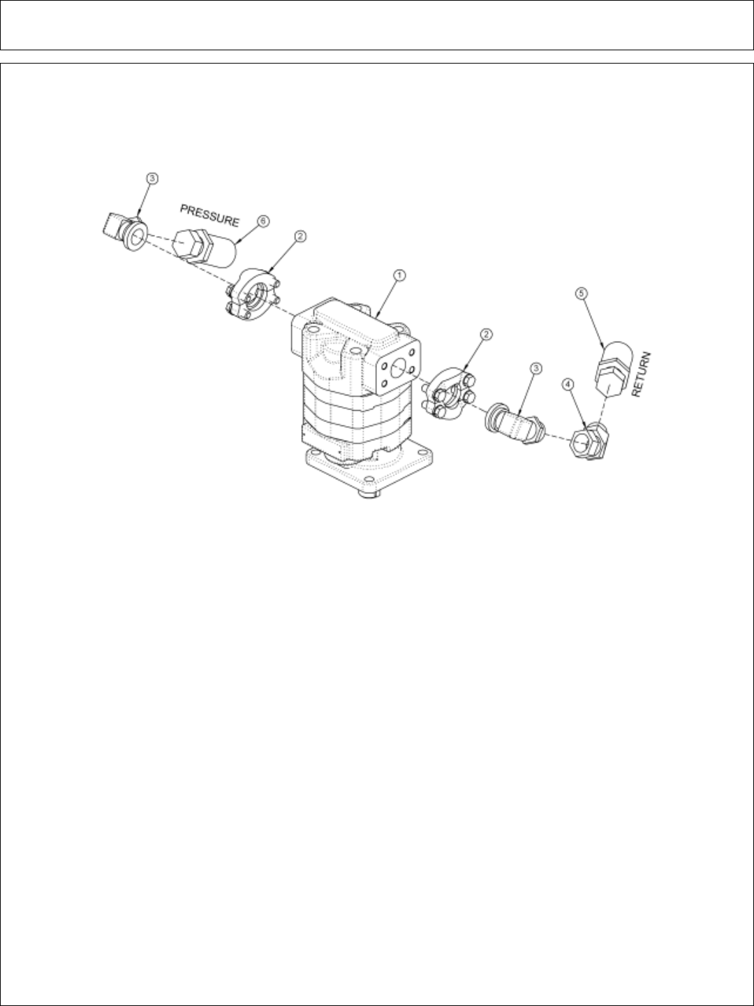
Side Rotary Common Section 6 - 20
TM72” MOTOR ASSEMBLY
ITEM PART NO. QTY. DESCRIPTION
1 06504018 1 MOTOR
2 TF4852 2 KIT,FLANGE,#20
3 34943 2 ELBOW,#20FLG x #16MJ
4 24724 1 ELBOW,#16FJX x #16MJ45
5 06500444 1 HOSE,#16 x 141
6 06500445 1 HOSE,#16 x 145

Side Rotary Common Section 6 - 21
PAGE
INTENSIONALLY
LEFT
BLANK
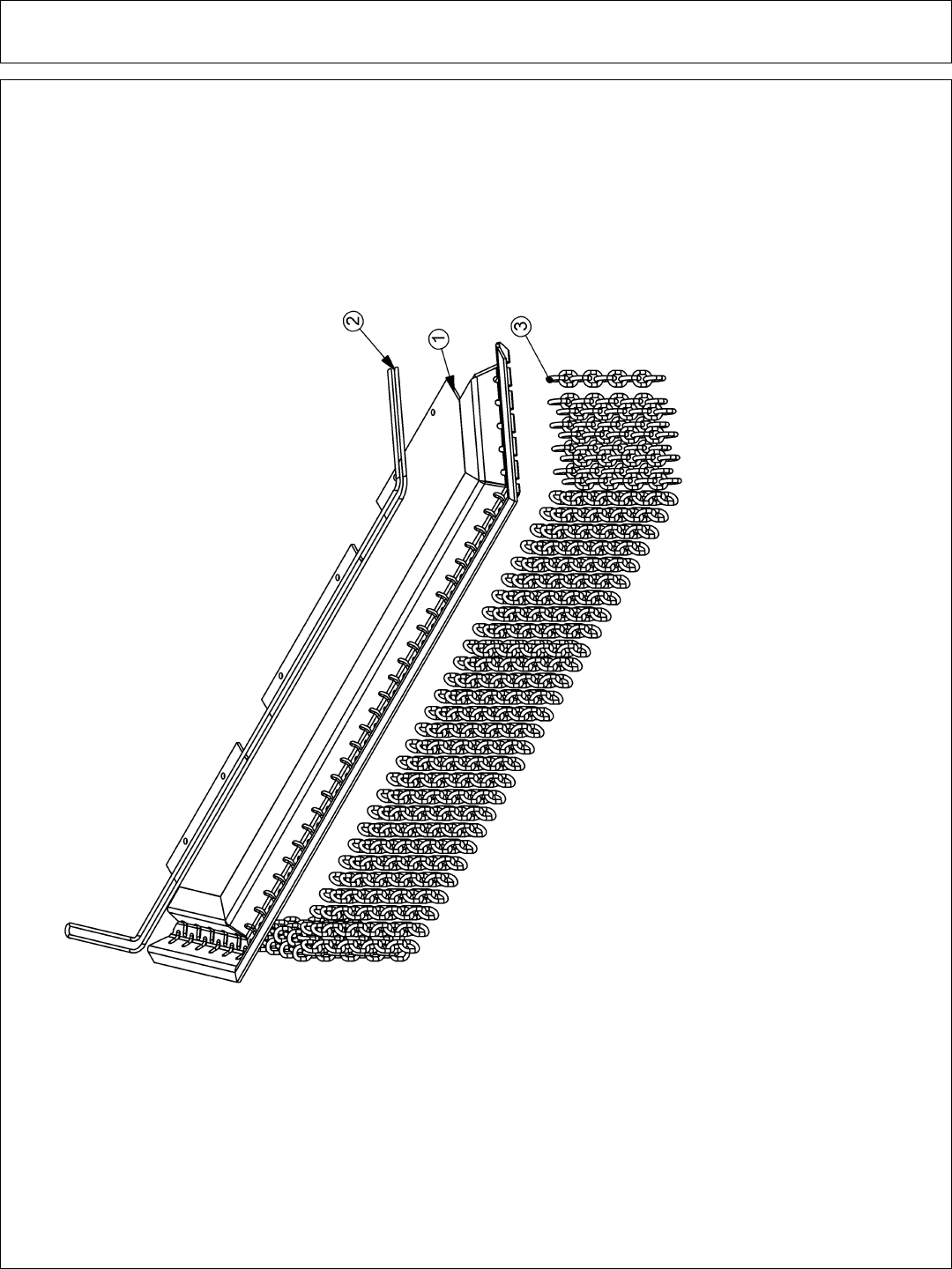
Side Rotary Common Section 6 - 22
CHAIN GUARDS

Side Rotary Common Section 6 - 23
SIDE ROTARY CHAIN GUARDS
60” SIDE ROTARY
ITEM PART NO. QTY. DESCRIPTION
31773 STD. GAURD,CHAIN,SR60,FRONT ASSY
1 31762 1 GUARD,CHAIN,TM60,FRONT
2 28407 12’ CABLE, 5/16”, BULK
3 22993 77 CHAIN, 5/16” GR30, 9 LINK
** 28408 4 U-BOLT, CABLE, 5/16”
** NOT SHOWN
72” SIDE ROTARY
ITEM PART NO. QTY. DESCRIPTION
31931 STD. GAURD,CHAIN,SR72,FRONT ASSY
1 31863 1 GUARD,CHAIN,TM72,FRONT
2 28407 14’ CABLE, 5/16”, BULK
3 22993 91 CHAIN, 5/16” GR30, 9 LINK
** 28408 4 U-BOLT, CABLE, 5/16”
** NOT SHOWN
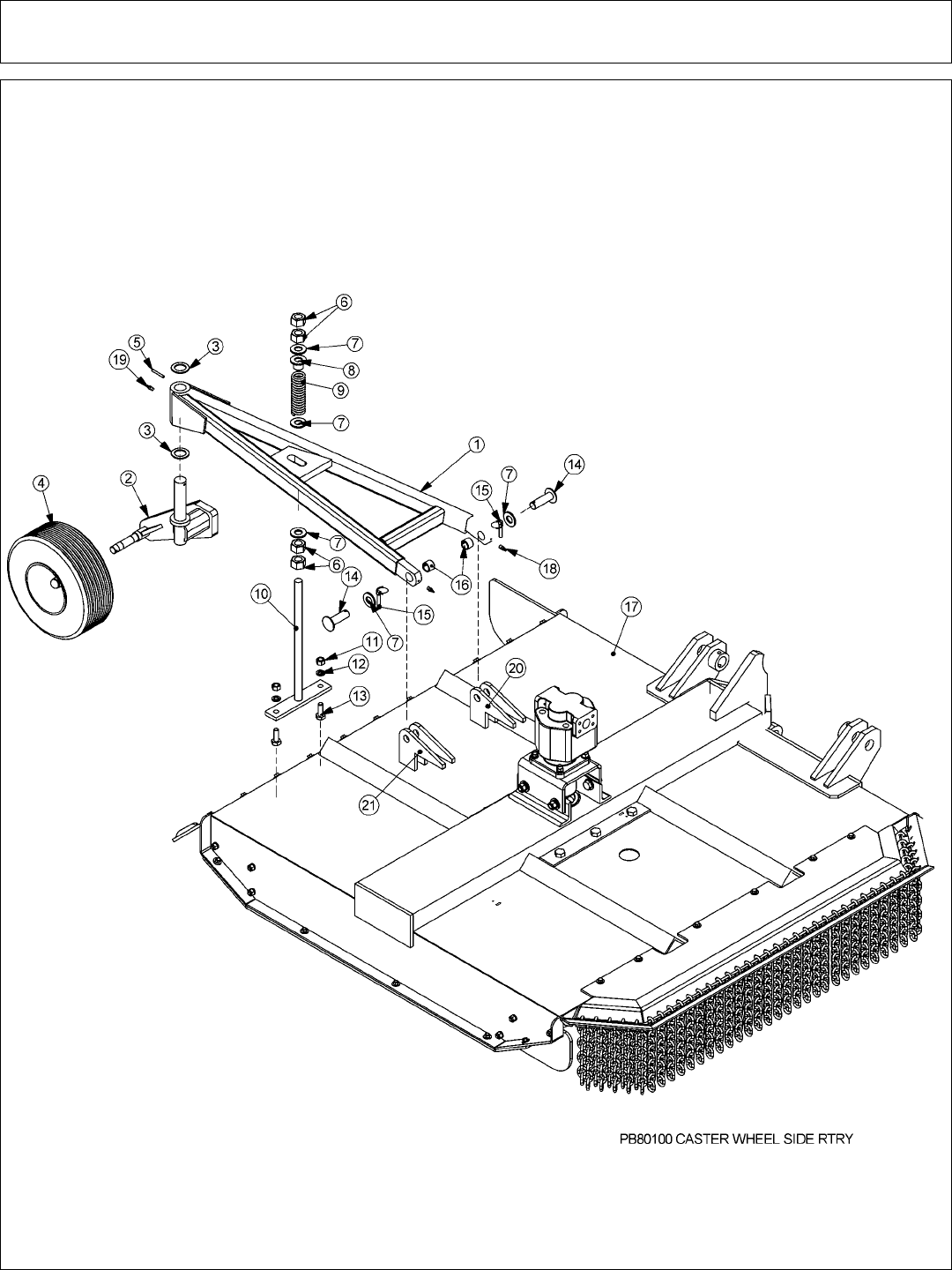
Side Rotary Common Section 6 - 24
SIDE ROTARY CASTER WHEEL ASSEMBLY

Side Rotary Common Section 6 - 25
SIDE ROTARY CASTER WHEEL ASSEMBLY
ITEM PART NO. QTY. DESCRIPTION
1 25214C 1 FRAME,CASTER,WHL,TM60,W/O CG
2 22057C 1 SPINDLE, CASTER AXLE, ASSY
3 6T2617 2 BUSHING,MACH,1-1/2IDX 2-1/4OD
4 28548 1 CASTER WHEEL, SOLID TIRE
** 22065 1 HUB ASSY, REAR ROTARY
** 22066 1 HUB, CASTER (REAR ROTARY)
** 22070 1 DUST CAP
** 22071 5 HUB STUD
** 22073 1 HEX NUT, 1”NF (SLOTTED)
** 22533 1 COTTER PIN, 3/16” x 2”
** 6T0830 2 BEARING, CONE, CASTER WHEEL
** 6T0838 1 SEAL
** 23329 1 WHEEL, CPLT, SOLID TIRE
** 21416 1 TIRE, SOLID, RR-RTRY
** 22697 1 RIM, OUTER/RR RTRY CASTER
** 22696 1 RIM, REAR ROTARY CASTER
5 6T3014 1 ROLL PIN, 1/4" x 2"
6 21925 4 HEX NUT,1" NC
7 22023 5 FLATWASHER,1"
8 22753 1 TUBE, PROTECTOR
9 22058 1 SPRING, REAR RTRY
10 22059B 1 ADJ ROD, TRR
11 21775 2 HEX NUT, 5/8
12 21992 2 LOCKWASHER, 5/8
13 21782 2 CAPSCREW, 5/8 x 1 3/4,NC
14 22060 2 CASTER FRAME PIN
15 TF1143 2 PIN, LYNCH, 7/16" x 2"
16 TB3010 2 BUSHING,1"
17 31460 1 RTRY,60" CPLT-HP,T3F,W/FRT CG
18 6T3207 2 GREASE ZERK,1/4" X STR
19 6T3211 1 GREASE ZERK,1/8" X STR
20 21441 2 CASTER FRAME ANCHOR GUSSET
21 21442 2 CASTER FRAME ANCHOR GUSSET
NOTE: CASTER WHEEL ASSEMBLY IS BROKEN DOWN LATER IN THE MANUAL
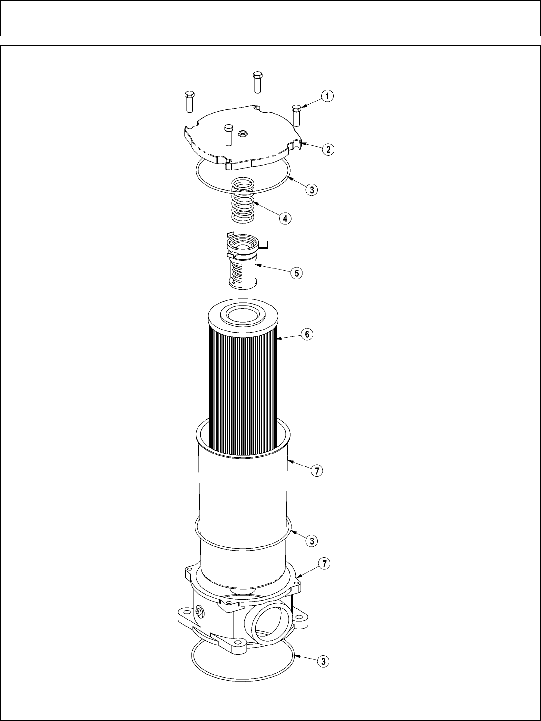
Side Rotary Common Section 6 - 26
RESERVOIR TANK FILTER ASSEMBLY

Side Rotary Common Section 6 - 27
RESERVOIR TANK FILTER ASSEMBLY
ITEM PART NO. QTY. DESCRIPTION
06505044 AVAIL FILTER ASSY SAE 10 MICRON
1 28583 4 CAPSCREW,8MMX25MM(1.25 PITCH)
2 06505045 1 COVER
3 06505046 1 SEAL KIT
4 06505047 1 SPRING
5 06505048 1 BYPASS
6 35259 1 FILTER,10 MIC,RETURN LINE
7 06505049 1 CAN/BODY
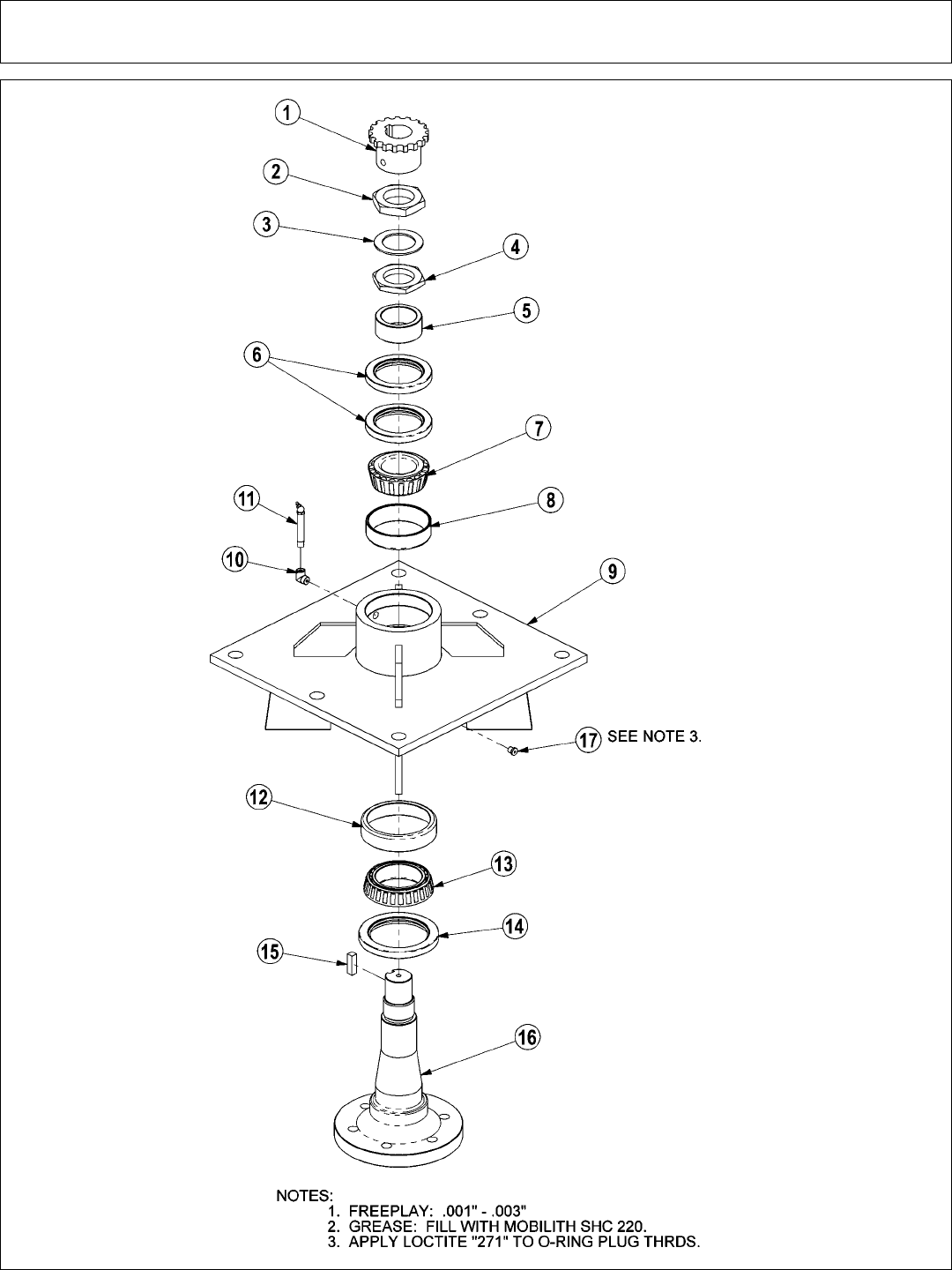
Side Rotary Common Section 6 - 28
MOWER SPINDLE ASSEMBLY - 6T1024H5

Side Rotary Common Section 6 - 29
MOWER SPINDLE ASSEMBLY - 6T1024H5
ITEM PART NO. QTY. DESCRIPTION
6T1024H5 AVAIL SPINDLE ASSEMBLY COMPLETE
1 6T1031 1 SPROCKET
2 6T1016 1 BEARING LOCK NUT - THICK
3 22596 1 JAM WASHER
4 6T1015 1 BEARING ADJUSTMENT NUT - THIN
5 6T1014 1 BEARING ADJUSTMENT SLEEVE
6 6T1011 1 UPPER SEAL - SET OF 2
7 6T1012 1 BEARING CONE
8 6T1013 1 BEARING CUP
9 6T1010H 1 SPINDLE HOUSING
10 30570 1 FITTING STREET ELBOW
11 33990 1 GREASE ZERK
12 6T1013H 1 BEARING CUP
13 6T1012H 1 BEARING CONE
14 6T1011H 1 LOWER SEAL
15 6T1019 1 SPINDLE KEY
16 PT1018H-5 1 SPINDLE
17 06503064 1 O-RING PLUG, 1/8”
* 32572 AVAIL SPINDLE REBUILD KIT (INCLUDE
ITEMS 2 THRU 8 AND 12 THRU 15)
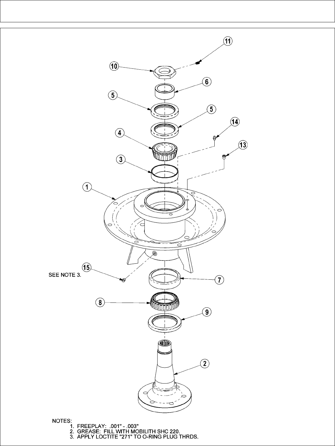
Side Rotary Common Section 6 - 30
MOWER SPINDLE ASSEMBLY - 34980

Side Rotary Common Section 6 - 31
MOWER SPINDLE ASSEMBLY - 34980
ITEM PART NO. QTY. DESCRIPTION
1 34978 1 SPINDLE MOUNT
2 34979 1 SPINDLE,TM60",NEW
3 6T1013 1 BEARING CUP
4 6T1012 1 BEARING,CONE
5 6T1011 2 SEAL,UPPER (SET OF 2)
6 6T1014 1 SLEEVE,ADJ BEARING
7 6T1013H 1 BEARING CUP,HD
8 6T1012H 1 BEARING,CONE,HD
9 6T1011H 1 SEAL,LOWER (HD)
10 34985 1 NUT W/SETSCREW
11 6T2275 1 SETSCREW,5/16x1/2,NC
13 34988 1 RELIEF,1PSI,1/8NPT
14 6T3207 1 ZERK,1/4" x STR
15 06503064 1 O-RING PLUG, 1/8”
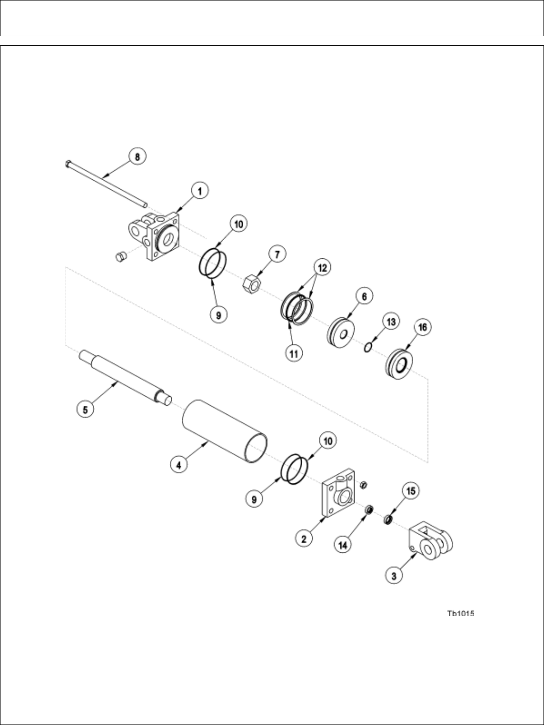
Side Rotary Common Section 6 - 32
HYDRAULIC LIFT CYLINDER

Side Rotary Common Section 6 - 33
HYDRAULIC LIFT CYLINDER
3” X 12” CYLINDER # 32215
ITEM PART NO. QTY. DESCRIPTION
1 6T0167 1 CYLINDER BUTT
2 6T0170 1 CYLINDER GLAND
3 6T0178 1 CLEVIS END
4 6T0204 1 CYLINDER TUBE
5 6T0203 1 PISTON ROD
6 6T0173 1 PISTON
7 6T0179 1 LOCKNUT
8 6T0205 1 TIE ROD ASY
6T0187 AVAIL SEAL KIT
9 2 O - RING
10 2 BACK - UP WASHER
11 1 O - RING
12 2 BACK - UP WASHER
13 1 O - RING
14 1 U - CUP
15 1 WIPER
3” X 10” CYLINDER # 6T0151R
ITEM PART NO. QTY. DESCRIPTION
1 6T0167 1 CYLINDER BUTT
2 6T0170 1 CYLINDER GLAND
3 6T0178 1 CLEVIS END
4 6T0164 1 CYLINDER TUBE
5 6T0161 1 PISTON ROD
6 6T0173 1 PISTON
7 6T0179 1 LOCKNUT
8 6T0176 4 TIE ROD ASY
6T0187 AVAIL SEAL KIT
9 2 O - RING
10 2 BACK - UP WASHER
11 1 O - RING
12 2 BACK - UP WASHER
13 1 O - RING
14 1 U - CUP
15 1 WIPER
3” X 18” CYLINDER # 6T0150
ITEM PART NO. QTY. DESCRIPTION
1 6T0167 1 CYLINDER BUTT
2 6T0170 1 CYLINDER GLAND
3 6T0178 1 CLEVIS END
4 6T0165 1 CYLINDER TUBE
5 6T0162 1 PISTON ROD
6 6T0173 1 PISTON
7 6T0179 1 LOCKNUT
8 6T0177 1 TIE ROD ASY
6T0187 AVAIL SEAL KIT
9 2 O - RING
10 2 BACK - UP WASHER
11 1 O - RING
12 2 BACK - UP WASHER
13 1 O - RING
14 1 U - CUP
15 1 WIPER
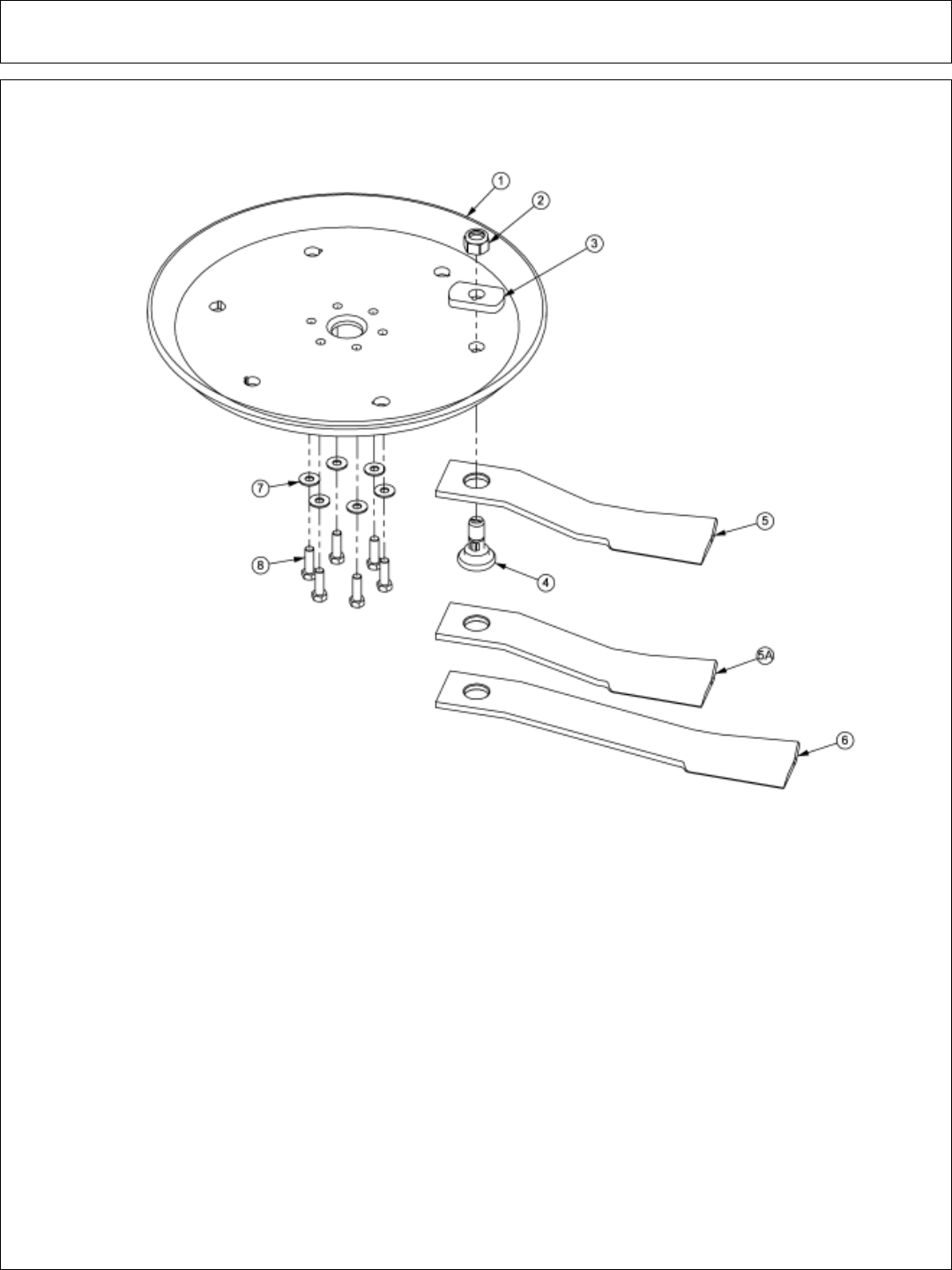
Side Rotary Common Section 6 - 34
ROTARY KNIVES AND DISKS
ITEM PART NO. QTY. DESCRIPTION
1 34876 1 BLADE MOUNTING DISK
2 6T1023R 2 NYLOCK HEX NUT 1 1/8”
3 34878 2 SPACER
4 34497 2 KNIFE MOUNTING BOLT
5 34685 2 KNIFE,60" HIGH SUCTION - STANDARD
5A 34684 2 KNIFE,60" - OPTIONAL
6 34682 2 KNIFE 72” - MOUNT ON 72” MOWER ONLY
7 25270 6 FLATWASHER,5/8,USS,GR8
8 6T2290 6 CAPSCREW,5/8 x 2
* 6T1825 * LOCTITE - USED ON ALL DISK MOUNTING BOLTS
* 27167 AVAIL BOLT KIT (INCLUDE ITEMS 7 & 8)
* 06700002 AVAIL KIT,60/72,DISK,KNF MTG (INCLUDE ITEM 1, 3,7 & 8)
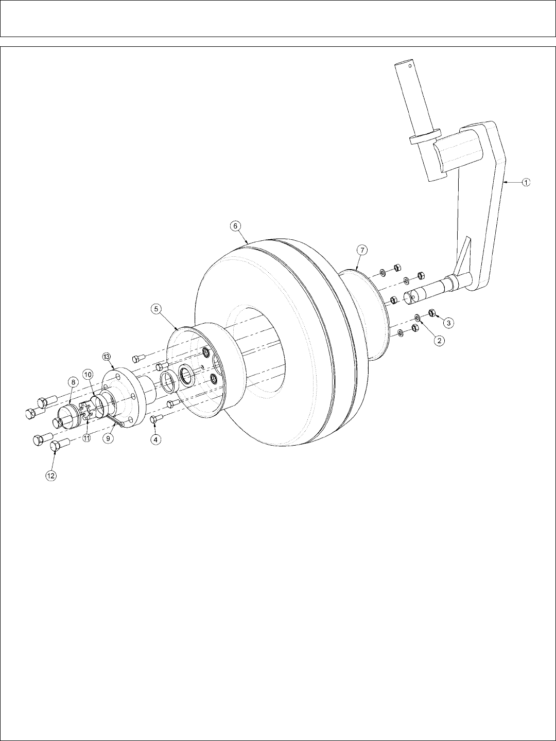
Side Rotary Common Section 6 - 35
CASTER WHEEL ASSEMBLY
ITEM PART NO. QTY. DESCRIPTION
1 21459 1 SPINDLE, CASTER WHEEL AXLE
2 21987 5 LOCKWASHER, 5/16”
3 21575 5 HEX NUT, 5/16”
4 28548 5 CAPSCREW, 5/16” x 3/4”, NC
5 22697-1 1 RIM, OUTER/RR RTRY CASTER ASSY
6 21416 1 TIRE,SOLID,RR-RTRY
7 22696-1 1 RIM,REAR ROTARY CASTER
8 22070 1 DUST CAP
9 22533 1 COTTER PIN, 3/16” X 2”
10 6T0836 2 CUP, CASTER WHEEL
11 22073 1 HEX NUT,1NF(SLOTTED JAM NUT)
12 22071 5 HUB STUD
13 22066-1 1 HUB CASTER (REAR ROTARY)
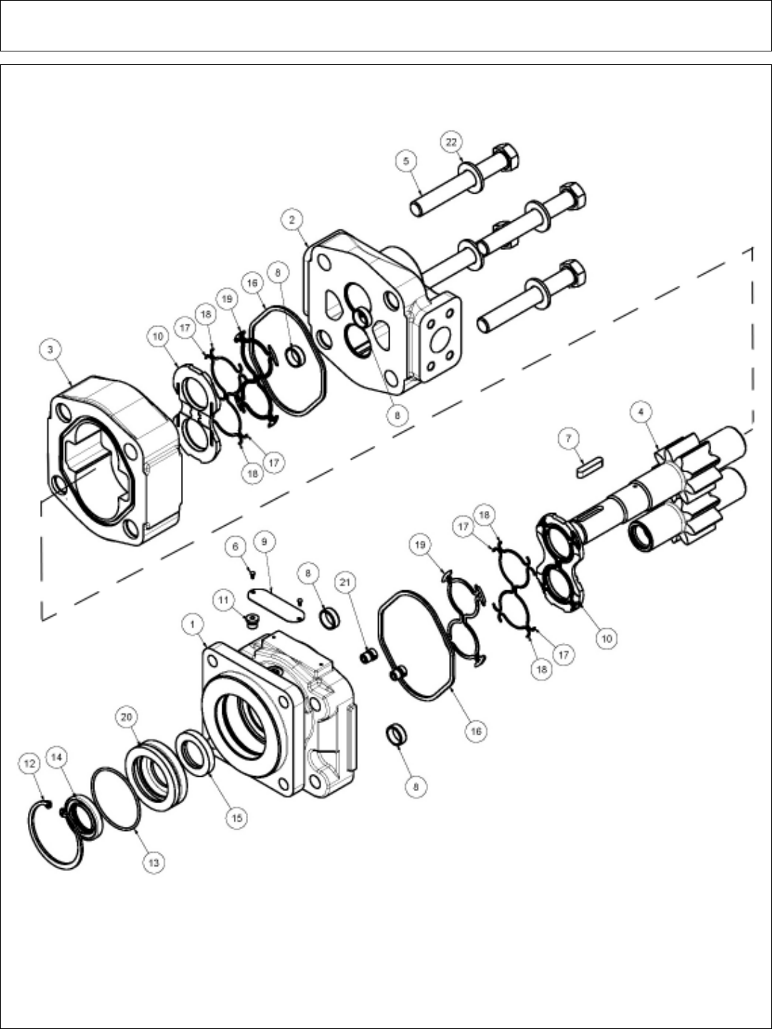
Side Rotary Common Section 6 - 36
ROTARY MOTOR

Side Rotary Common Section 6 - 37
ROTARY MOTOR
ITEM PART NO. QTY. DESCRIPTION
06504018 MOTOR
06504103 1 SEAL KIT
1 22790 1 HOUSING, SEC
2 06504088 1 HOUSING, SEC
3 06504062 1 HOUSING, GEAR
4 06504105 1 SET, GEAR SHAFT
5 06504106 4 CAP SCREW
6 06504078 2 SCREW, DRIVE
7 06504092 1 KEY
8 06504093 4 PIN, DOWEL
9 06504094 1 NAME PLATE
10 06504095 2 THRPL
11 02961940 1 PLUG, ODT
12 02962200 1 RING, SNAP
13 06504096 1 O RING
14 6T5101 1 SEAL, LIP
15 06504097 1 SEAL, LIP
16 22797 2 SEAL, SQ-R
17 06504098 4 SEAL, SIDE CHAN
18 06504099 4 SEAL, END CHAN
19 06504100 2 SEAL, BK-UP
20 06504101 1 RTNR, SEAL
21 6T5809 2 CHECK ASS’Y
22 06504102 4 WASHER
ITEM PART NO. QTY. DESCRIPTION
* 06504011 AVAIL MOTOR
06504103 1 SEAL KIT
1 22790 1 HOUSING, SEC
2 06504088 1 HOUSING, PEC
3 06504062 1 HOUSING, GEAR
4 06504090 1 SET, GEAR SHAFT
5 06504104 4 CAP SCREW
6 06504078 2 SCREW, DRIVE
7 06504092 1 KEY
8 06504093 4 PIN, DOWEL
9 06504094 1 NAME PLATE
10 06504095 2 THRPL
11 02961940 1 PLUG, ODT
12 02962200 1 RING, SNAP
13 06504096 1 O RING
14 6T5101 1 SEAL, LIP
15 06504097 1 SEAL, LIP
16 22797 2 SEAL, SQ-R
17 06504098 4 SEAL, SIDE CHAN
18 06504099 4 SEAL, END CHAN
19 06504100 2 SEAL, BK-UP
20 06504101 1 RTNR, SEAL
21 6T5809 2 CHECK ASS’Y
22 06504102 4 WASHER
60” ROTARY MOTOR
72” ROTARY MOTOR
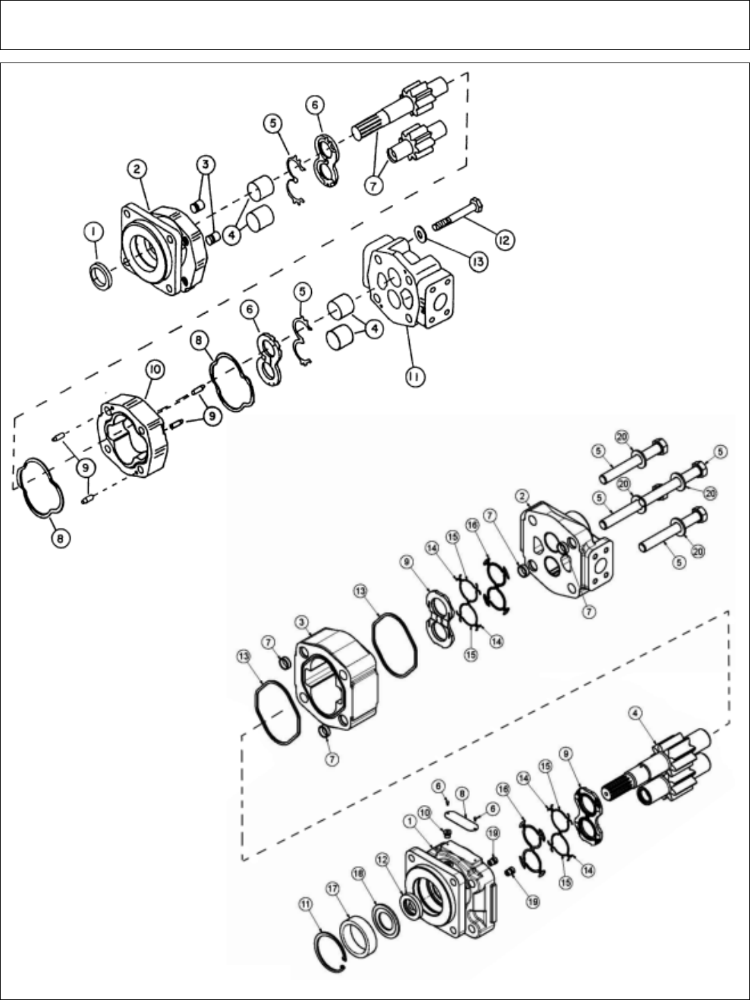
Side Rotary Common Section 6 - 38
HYDRO PUMP & TSR MOTOR
TSR MOTOR
FRONT PUMP

Side Rotary Common Section 6 - 39
HYDRO PUMP & TSR MOTOR
FRONT HYDRAULIC PUMP
ITEM PART NO. QTY. DESCRIPTION
23152 AVAIL PUMP ASSEMBLY 1 3/4” COMPLETE
1 22765 1 SEAL (INCLUDED IN SEAL KIT)
2 22766 1 SHAFT END COVER
3 22767 2 CHECK AND END COVER
4 22768 2 BUSHING
5 22769 2 CHANNEL SEAL (INCLUDED IN SEAL KIT)
6 22770 2 THRUST PLATE (INCLUDED IN SEAL KIT)
7 22771 SET DRIVE SHAFT AND GEAR SET 1 3/4”
8 22772 2 GASKET SEAL (INCLUDED IN SEAL KIT)
9 22773 4 DOWEL PINS
10 22774 1 GEAR HOUSING 1 3/4”
11 22779 1 PORT END COVER
12 23824 4 STUDS
13 22781 SET WASHER
6T5322 AVAIL SEAL APPLICATOR TOOL
24150 AVAIL SEAL KIT (INCLUDES 1, 5, 6 AND 8)
TSR MOTOR
ITEM PART NO. QTY. DESCRIPTION
06504016 AVAIL MOTOR(M365-1 1/4SPLINE),SEALED
1 22790 1 HOUSING, SEC
2 06504088 1 HOUSING, PEC
306504111 1 HOUSING, GEAR
4 06504110 1 SET, GEAR SHAFT
5 06504104 4 CAP SCREW
6 06504078 2 SCREW, DRIVE
7 06504093 4 PIN, DOWEL
8 06504094 1 NAME PLATE
9 06504095 2 THRPL
10 02961940 1 PLUG, ODT (0.25)
11 6T5200 1 RING, SNAP
12 06504097 1 SEAL, LIP
13 22797 2 SEAL, SQ-R
14 06504098 4 SEAL, SIDE CHAN
15 06504099 4 SEAL, END CHAN
16 06504100 2 SEAL, BK-UP
17 06504112 1 SPACER
18 06504113 1 RTNR, SEAL
19 6T5809 2 CHECK ASS’Y
20 06504102 4 WASHER
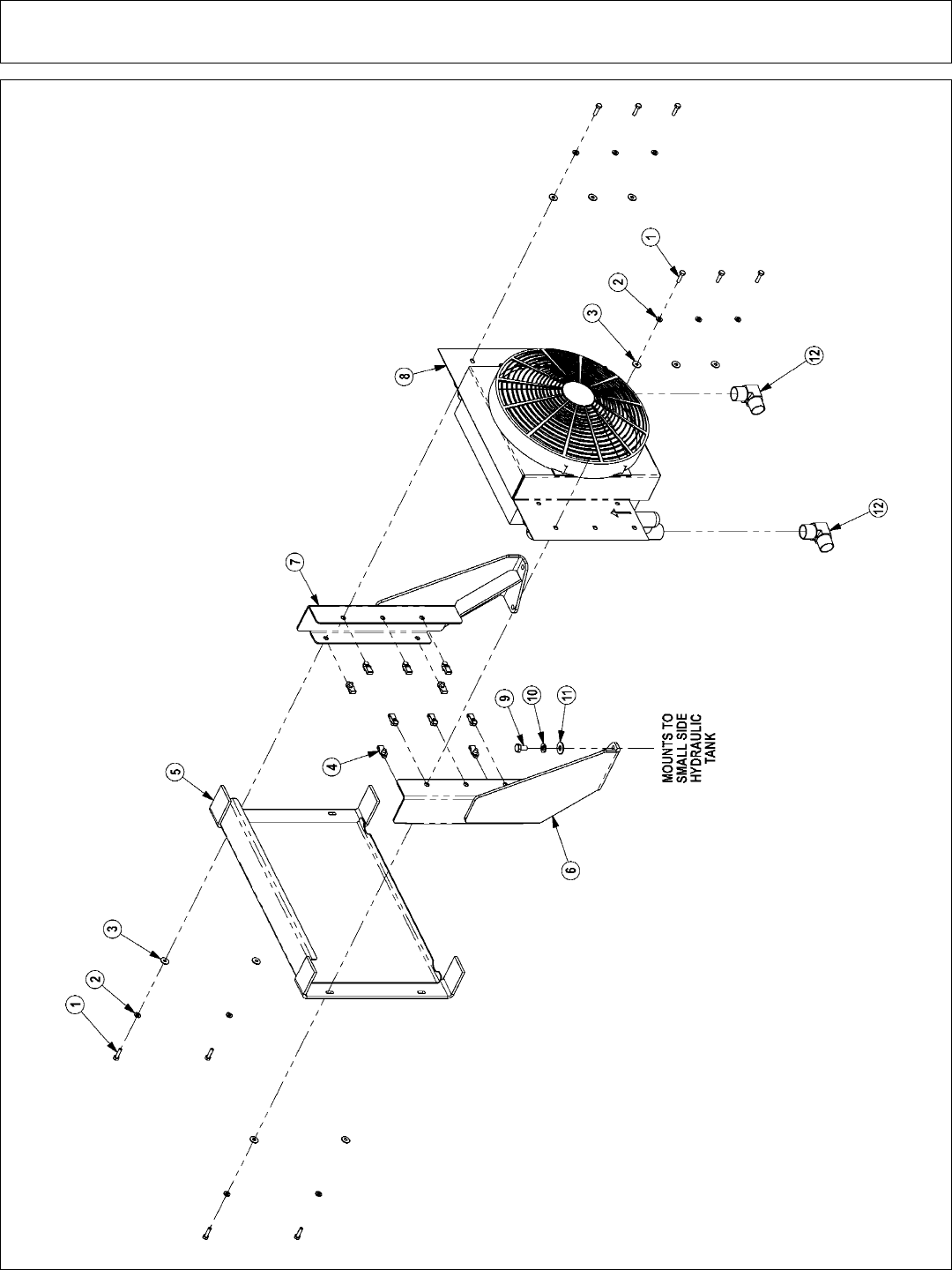
Side Rotary Common Section 6 - 40
SIDE COOLER

Side Rotary Common Section 6 - 41
SIDE COOLER
ITEM PART NO. QTY. DESCRIPTION
1 21530 10 CAPSCREW,1/4 X1 NC
2 21986 10 LOCKWASHER,1/4
3 22014 10 FLATWASHER,1/4
4 35176 10 1/4 U-NUT
5 06370015 1 SCREEN,COOLER,FRNT
6 06380006 1 MNT,COOLER,BUMPER TANK,RH
7 06380007 1 MNT,COOLER,BUMPER TANK,LH
8 06510026 1 COOLER,FRONT MNT
9 21629 4 CAPSCREW,3/8 X 3/4 NC
10 21988 4 LOCKWASHER,3/8
11 22016 4 FLATWASHER,3/8
12 34117 2 ELBOW,1MOR X 1MJ90,FORGED

Side Rotary Common Section 6 - 42
2SP HUSCO - POWER BEYOND (30801)

Side Rotary Common Section 6 - 43
2SP HUSCO - POWER BEYOND (30801)
ITEM PART NO. QTY DESCRIPTION
1 TB1017S 1 INLET END COVER
2 TB1702 1 END COVER, POWER BEYOND
3 TB1017P 1 VALVE SECTION (SINGLE ACTING, SPRING DETENT)
4 06502091 1 VALVE SECTION (DOUBLE ACTING, CENTER SPRING)
(NO AUX VALVE PORTS)
5 N/A - N/A
6 N/A - N/A
7 TB1017M 1 SHUT-OFF PLUG
8 TB1017E 1 RELIEF VALVE, 2250 PSI
9 TB1017M 1 SHUT-OFF PLUG
10 N/A - N/A
11 TB1017A 2 VALVE SEAL KIT (FOR ONE SECTION)
11A 2 WIPER
11B 2 O-RING SMALL
11C 1 O-RING LARGE
11D 1 SPRING
11E 1 PUCKET
12 TB1017L 2 LEVER KIT (FOR ONE SECTION)
12A 1 LEVER KNOB
12B 1 LEVER
12C 2 LEVER WASHER
12D 1 LEVER CLIP
12E 2 LINKAGE
12F 1 LEVER PIN
12G 1 ROLL PIN
12H 1 LEVER BOOT
12J 1 LEVER BOLT
12K 1 LEVER DUST COVER
12L 1 LEVER NUT
13 TB1017X 1 TIE ROD KIT
14 24214 1 O-RING, LARGE

Side Rotary Common Section 6 - 44
2 SP HUSCO - LOAD SENSE (31320)

Side Rotary Common Section 6 - 45
2 SP HUSCO - LOAD SENSE (31320)
ITEM PART NO. QTY DESCRIPTION
1 31595 1 INLET END COVER
2 31594 1 END COVER, LOAD SENSE
3 31597 1 VALVE SECTION (DOUBLE ACTING, CENTER SPRING)
4 31597 1 VALVE SECTION (DOUBLE ACTING, CENTER SPRING)
5 06503067 1 RELIEF PLUG
6 06503067 1 RELIEF PLUG
7 N/A - N/A
8 6T4209 1 RELIEF PLUG
9 31862 1 RELIEF VALVE, 2175 PSI
10 31862 1 RELIEF VALVE, 2175 PSI
11 31593 2 VALVE SEAL KIT (FOR ONE SECTION)
11A 2 WIPER
11B 2 O-RING SMALL
11C 1 O-RING LARGE
11D 1 SHUTTLE DISC
11E 1 SPRING
12 TB1017L 2 LEVER KIT (FOR ONE SECTION)
12A 1 LEVER KNOB
12B 1 LEVER
12C 2 LEVER WASHER
12D 1 LEVER CLIP
12E 2 LINKAGE
12F 1 LEVER PIN
12G 1 ROLL PIN
12H 1 LEVER BOOT
12J 1 LEVER BOLT
12K 1 LEVER DUST COVER
12L 1 LEVER NUT
13 31603 2 COMPENSATOR
14 TB1017X 1 TIE ROD KIT
15 24214 1 O-RING, LARGE
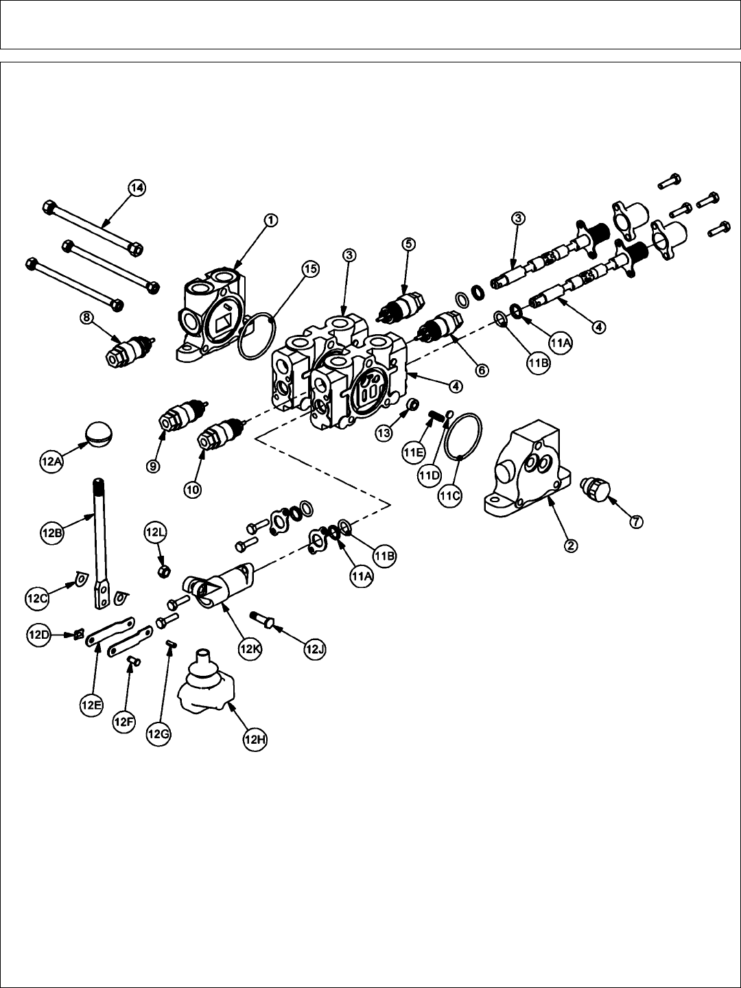
Side Rotary Common Section 6 - 46
2 SP HUSCO - LOAD SENSE (31321)

Side Rotary Common Section 6 - 47
2 SP HUSCO - LOAD SENSE (31321)
ITEM PART NO. QTY DESCRIPTION
1 31595 1 INLET END COVER
2 31594 1 END COVER, LOAD SENSE
3 31597 1 VALVE SECTION (DOUBLE ACTING, CENTER SPRING)
4 31597 1 VALVE SECTION (DOUBLE ACTING, CENTER SPRING)
5 06503067 1 RELIEF PLUG
6 31861 1 RELIEF VALVE, 360 PSI
7 N/A - N/A
8 6T4209 1 RELIEF PLUG
9 31862 1 RELIEF VALVE, 2175 PSI
10 31862 1 RELIEF VALVE, 2175 PSI
11 31593 2 VALVE SEAL KIT (FOR ONE SECTION)
11A 2 WIPER
11B 2 O-RING SMALL
11C 1 O-RING LARGE
11D 1 SHUTTLE DISC
11E 1 SPRING
12 TB1017L 2 LEVER KIT (FOR ONE SECTION)
12A 1 LEVER KNOB
12B 1 LEVER
12C 2 LEVER WASHER
12D 1 LEVER CLIP
12E 2 LINKAGE
12F 1 LEVER PIN
12G 1 ROLL PIN
12H 1 LEVER BOOT
12J 1 LEVER BOLT
12K 1 LEVER DUST COVER
12L 1 LEVER NUT
13 31603 2 COMPENSATOR
14 TB1017X 1 TIE ROD KIT
15 24214 1 O-RING, LARGE
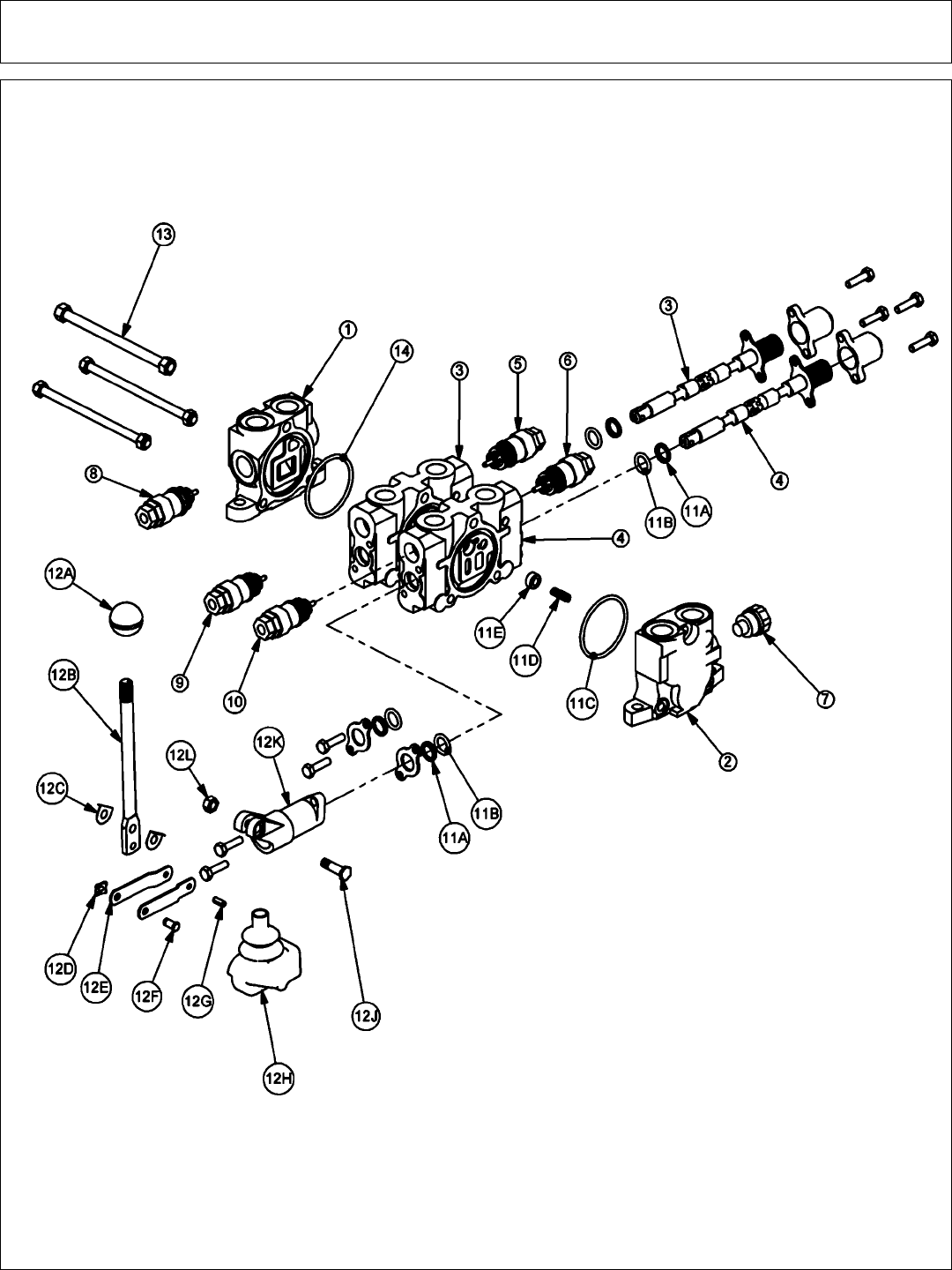
Side Rotary Common Section 6 - 48
2SP HUSCO - POWER BEYOND (31752)

Side Rotary Common Section 6 - 49
2SP HUSCO - POWER BEYOND (31752)
ITEM PART NO. QTY DESCRIPTION
1 TB1017S 1 INLET END COVER
2 TB1702 1 END COVER, POWER BEYOND
3 TB1017P 1 VALVE SECTION (SINGLE ACTING, SPRING DETENT)
4 TB1017P 1 VALVE SECTION (SINGLE ACTING, SPRING DETENT)
5 N/A - N/A
6 N/A - N/A
7 TB1017M 1 SHUT-OFF PLUG
8 TB1017E 1 RELIEF VALVE, 2250 PSI
9 TB1017M 1 SHUT-OFF PLUG
10 TB1017M 1 TB1017M
11 TB1017A 2 VALVE SEAL KIT (FOR ONE SECTION)
11A 2 WIPER
11B 2 O-RING SMALL
11C 1 O-RING LARGE
11D 1 SPRING
11E 1 PUCKET
12 TB1017L 2 LEVER KIT (FOR ONE SECTION)
12A 1 LEVER KNOB
12B 1 LEVER
12C 2 LEVER WASHER
12D 1 LEVER CLIP
12E 2 LINKAGE
12F 1 LEVER PIN
12G 1 ROLL PIN
12H 1 LEVER BOOT
12J 1 LEVER BOLT
12K 1 LEVER DUST COVER
12L 1 LEVER NUT
13 TB1017X 1 TIE ROD KIT
14 24214 1 O-RING, LARGE

Side Rotary Common Section 6 - 50
2SP HUSCO - LOAD SENSE (06502040)

Side Rotary Common Section 6 - 51
2SP HUSCO - LOAD SENSE (06502040)
ITEM PART NO. QTY DESCRIPTION
1 31595 1 INLET END COVER
2 31594 1 END COVER, LOAD SENSE
3 31597 1 VALVE SECTION (DOUBLE ACTING, CENTER SPRING)
4 31597 1 VALVE SECTION (DOUBLE ACTING, CENTER SPRING)
(REMOVE SHUTTLE DISC)
5 06503067 1 RELIEF PLUG
6 06503067 1 RELIEF PLUG
7 06503068 1 RELIEF PLUG
8 N/A - N/A
9 31862 1 RELIEF VALVE, 2175 PSI
10 31862 1 RELIEF VALVE, 2175 PSI
11 31593 2 VALVE SEAL KIT (FOR ONE SECTION)
11A 2 WIPER
11B 2 O-RING SMALL
11C 1 O-RING LARGE
11D 1 SHUTTLE DISC
11E 1 SPRING
12 TB1017L 2 LEVER KIT (FOR ONE SECTION)
12A 1 LEVER KNOB
12B 1 LEVER
12C 2 LEVER WASHER
12D 1 LEVER CLIP
12E 2 LINKAGE
12F 1 LEVER PIN
12G 1 ROLL PIN
12H 1 LEVER BOOT
12J 1 LEVER BOLT
12K 1 LEVER DUST COVER
12L 1 LEVER NUT
13 31603 2 COMPENSATOR
14 TB1017X 1 TIE ROD KIT
15 24214 1 O-RING, LARGE

Side Rotary Common Section 6 - 52
2SP HUSCO - LOAD SENSE (06502042)

Side Rotary Common Section 6 - 53
2SP HUSCO - LOAD SENSE (06502042)
ITEM PART NO. QTY DESCRIPTION
1 31595 1 INLET END COVER
2 31594 1 END COVER, LOAD SENSE
3 31600 1 VALVE SECTION (DOUBLE ACTING, DETENT FLOAT)
4 31600 1 VALVE SECTION (DOUBLE ACTING, DETENT FLOAT)
(REMOVE SHUTTLE DISC)
5 06503067 1 RELIEF PLUG
6 31861 1 RELIEF VALVE 360 PSI
7 06503068 1 RELIEF PLUG
8 6T4209 1 RELIEF PLUG
9 31862 1 RELIEF VALVE, 2175 PSI
10 31862 1 RELIEF VALVE, 2175 PSI
11 31593 2 VALVE SEAL KIT (FOR ONE SECTION)
11A 2 WIPER
11B 2 O-RING SMALL
11C 1 O-RING LARGE
11D 1 SHUTTLE DISC
11E 1 SPRING
12 TB1017L 2 LEVER KIT (FOR ONE SECTION)
12A 1 LEVER KNOB
12B 1 LEVER
12C 2 LEVER WASHER
12D 1 LEVER CLIP
12E 2 LINKAGE
12F 1 LEVER PIN
12G 1 ROLL PIN
12H 1 LEVER BOOT
12J 1 LEVER BOLT
12K 1 LEVER DUST COVER
12L 1 LEVER NUT
13 31603 2 COMPENSATOR
14 TB1017X 1 TIE ROD KIT
15 24214 1 O-RING, LARGE
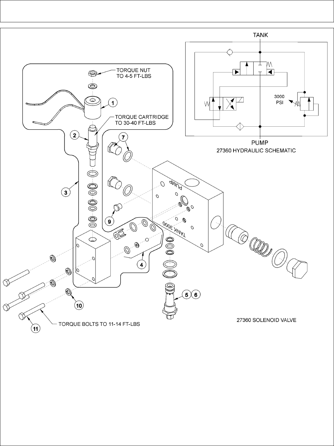
Side Rotary Common Section 6 - 54
ITEM PART NO. QTY. DESCRIPTION
06502007 AVAIL VALVE ASY HIGH PRESSURE
06502008 AVAIL VALVE ASY LOW PRESSUTE
1 34689 1 SOLENOID COIL
2 06505026 1 SOLENOID
3 06502009 1 SOLENOID VALVE KIT
4 6T3911 1 SOLENOID SEAL KIT
5 6T3908 1 RELIEF PILOT 2150 PSI LOW PRESSURE
6 6T3910 1 RELIEF PILOT 3400 PSI HIGH PRESSURE
7 6T4209 2 PLUG W/ O - RING
9 TF1228 1 PLUG 1/4” NPT HOLLOW HEX
10 21987 4 LOCKWASHER 5/16”
11 21586 4 CAPSCREW 5/16” X 2 1/2”
12-12-02
SOLENOID VALVE ASSEMBLY
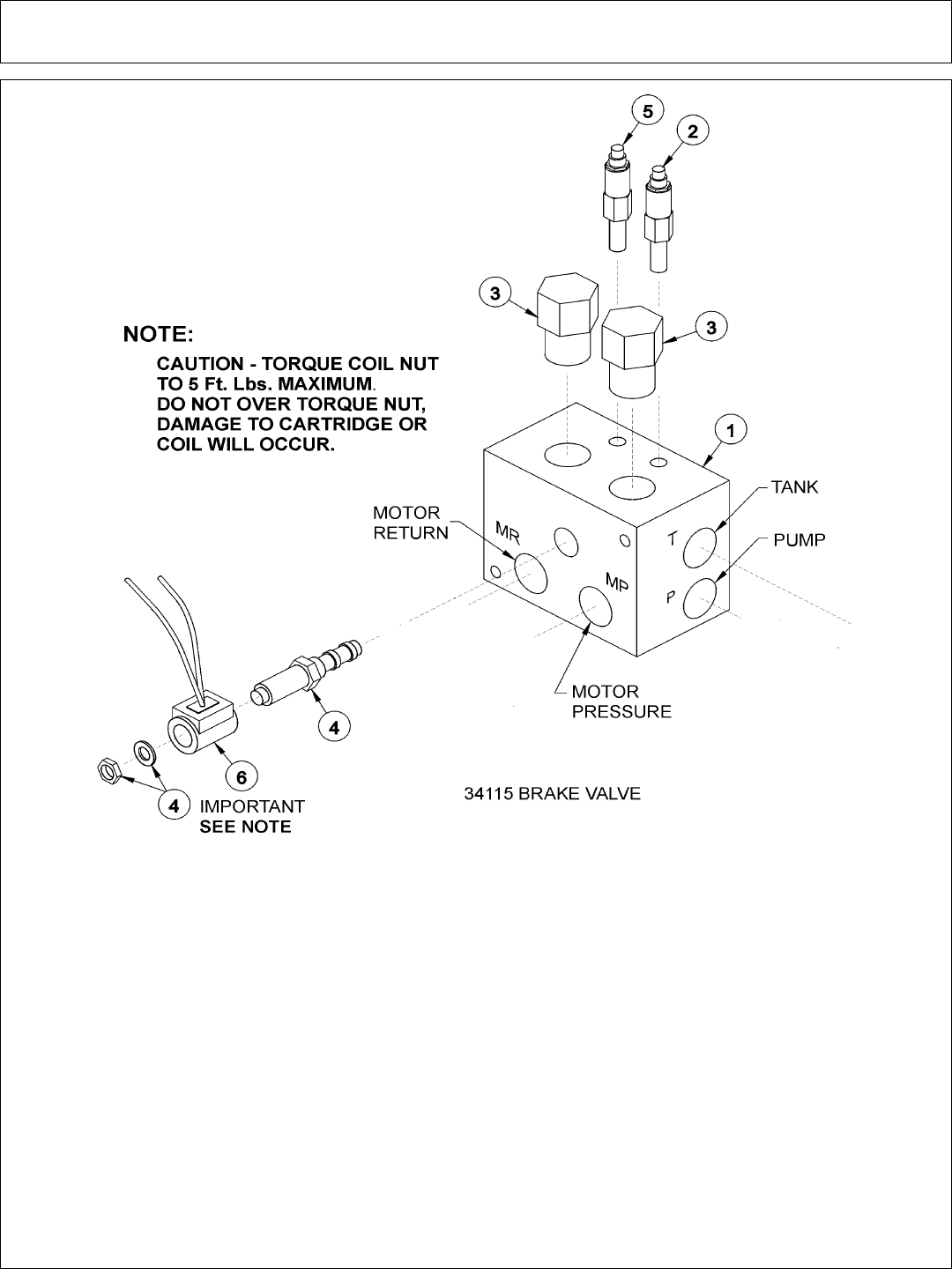
Side Rotary Common Section 6 - 55
SOLENOID BRAKE VALVE ASSEMBLY
ITEM PART NO. QTY. DESCRIPTION
* 34115 AVAIL SOLENOID BRAKE VALVE ASSEMBLY - HIGH PRESSURE
1 34092 1 BRAKE VALVE, BLANK
2 34095 1 RELIEF VALVE, 3000 PSI
3 34094 2 LOGIC ELEMENT
4 34093 1 CARTRIDGE, 2 POSITION, 3 WAY (WITH NUT & WASHER)
5 34091 1 RELIEF VALVE, 2600 PSI
6 34689 1 COIL, 12 VDC, BRAKE VALVE
** 34096 2 RELIEF SEAL KIT
** 34097 1 SOLENOID SEAL KIT
** 34098 2 ELEMENT SEAL KIT
12-17-02
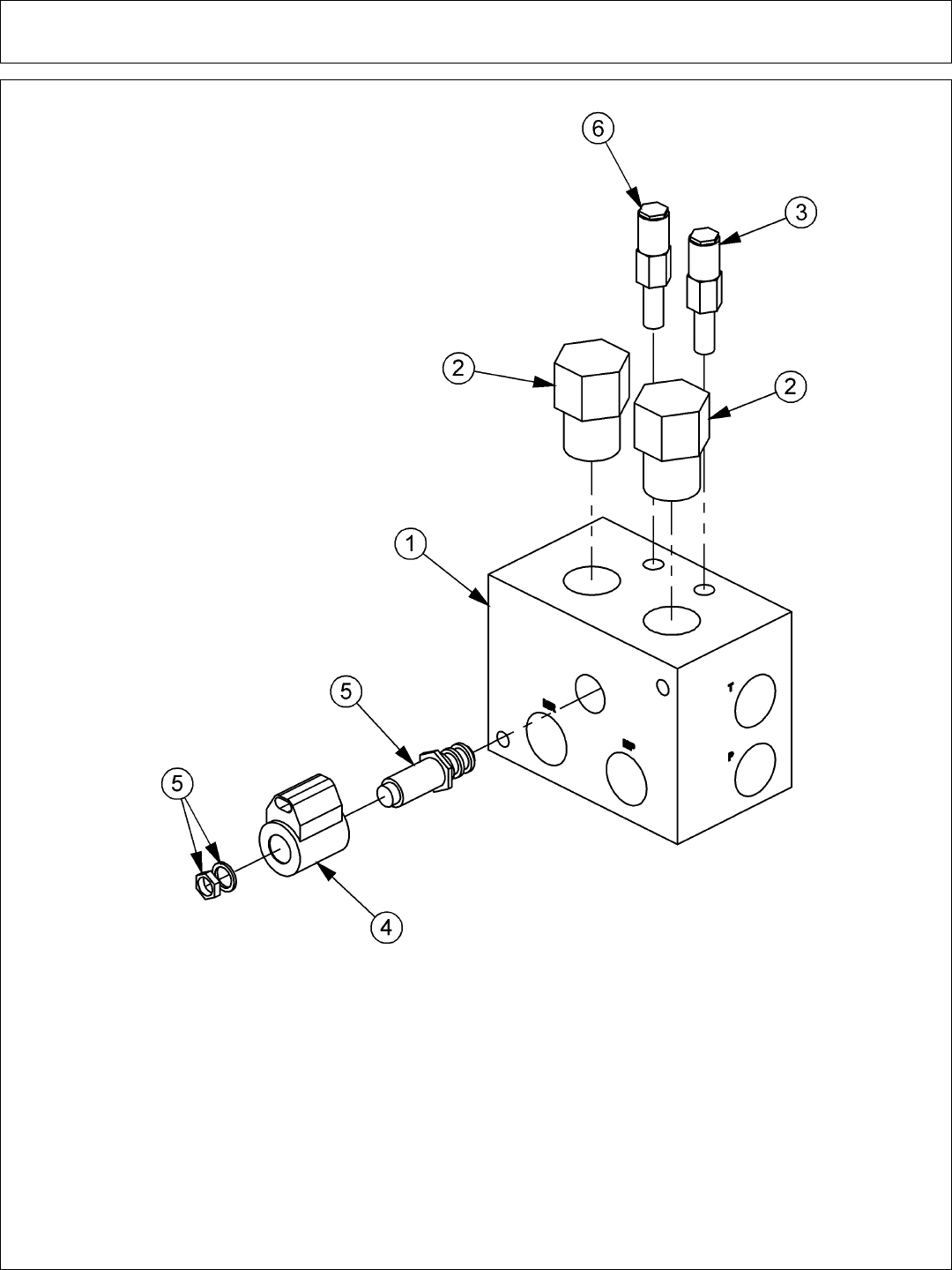
Side Rotary Common Section 6 - 56
BRAKE VALVE ASSEMBLY W/ METRI PAK
ITEM PART NO. QTY. DESCRIPTION
1 34092 1 BRAKE VALVE, BLANK
2 34094 2 LOGIC ELEMENT
3 34095 1 RELIEF VALVE, 3000 PSI
4 06510095 1 METRI PAK COIL
5 34093 1 CARTRIDGE, 2 POSITION, 3 WAY (WITH NUT & WASHER)
6 34091 1 RELIEF VALVE, 2600 PSI
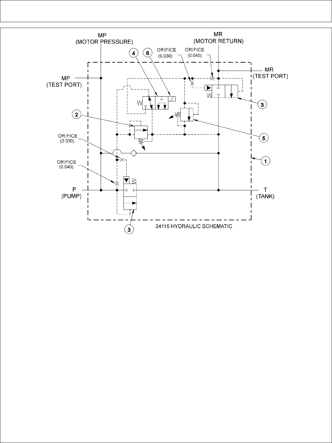
Side Rotary Common Section 6 - 57
SOLENOID BRAKE VALVE HYDRAULIC SCHEMATIC
BRAKE VALVE TROUBLESHOOTING
FAILURE MODE: CHECK STEPS
- MOWER WILL NOT START - system pressure is low
(engine not lugging). 1 thru 6
- MOWER WILL NOT START - system pressure is high
(engine lugging). “MR” port will be high pressure. 7
- MOWER WILL NOT ROTATE AT FULL SPEED - limited power. 3 thru 5
- MOWER BLADE WILL NOT STOP - blade will not stop in proper time. 7 thru 9
CORRECTIVE STEPS:
1. Check for voltage at solenoid (item 6), voltage must be between 10.2 volts and 13.8 volts.
2. Remove, inspect solenoid and cartridge (items 4, 6) for wear or contamination.
3. Remove, inspect logic elements near “P” port (item 3) for wear or contamination.
4. Remove, inspect 3000 psi relief valve (item 2) for wear or contamination.
5. Remove and inspect orifices near “P” port for contamination.
6. Remove “P” port hose and fitting, visually inspect for contamination, check ball for movement.
7. Remove and inspect orifices near “MR” port for contamination.
8. Remove, inspect 2600 psi relief valve (item 5) for wear of contamination.
9. Remove, inpect logic element near “MR” port (item 3) for wear or contamination.
7-25-02
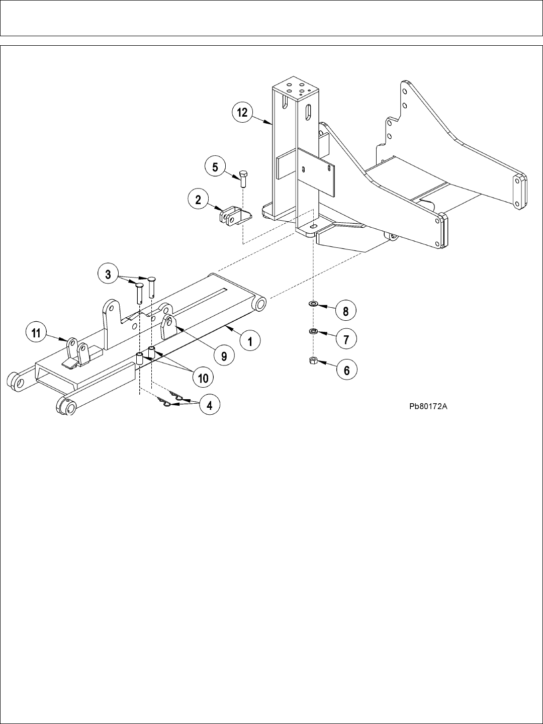
Side Rotary Common Section 6 - 58
TRAVEL LOCK LIFT BEAM
ITEM PART NO. QTY. DESCRIPTION
1 6T0105 1 DRAFT BEAM (STD WITH TRAVEL LOCKS)
2 6T0106 1 TRAVEL LOCK BRACKET
3 6T0107 2 TRAVEL LOCK PINS 3/4” X 3 1/4”
4 6T3020 2 R - CLIP 5/32”
5 21833 1 CAPSCREW 3/4” X 2 1/4”
6 21825 1 HEX NUT 3/4”
7 21993 1 LOCK WASHER 3/4”
8 22021 1 FLAT WASHER 3/4”
9 22600 1 TRAVEL LOCK EAR
10 22604 2 PIN HOLDER
11 22601C 1 TRAVEL LOCK ASY
12 * REF. MAIN FRAME REFER TO PARTS SECTION
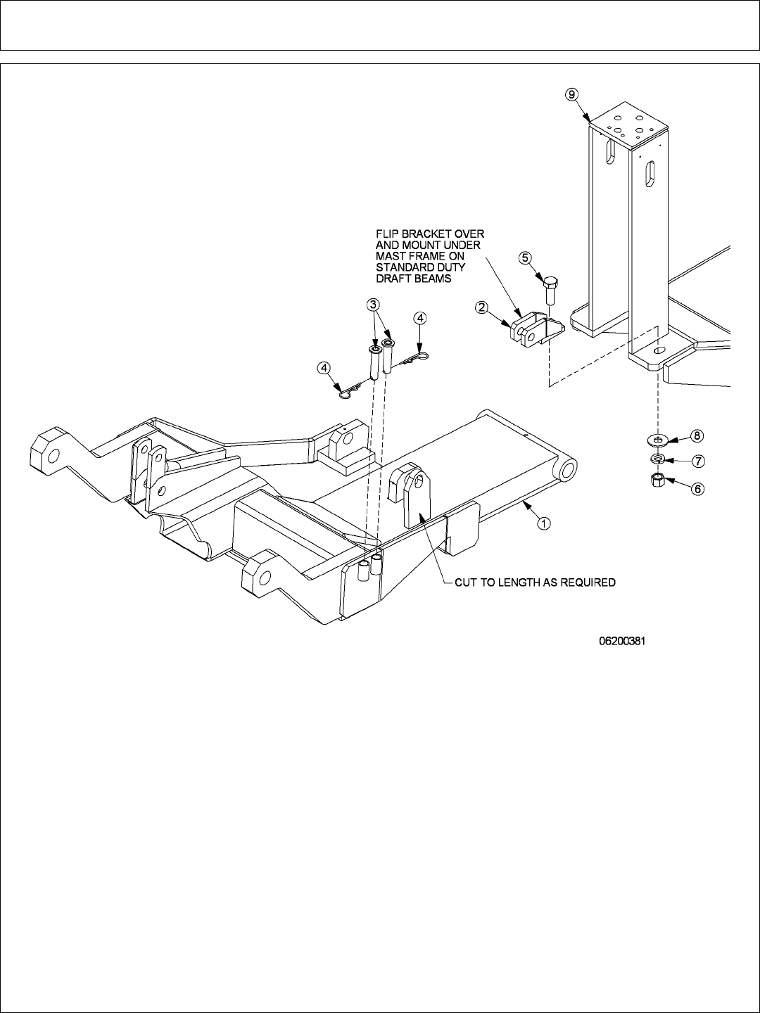
Side Rotary Common Section 6 - 59
SIDE MOWER TRAVEL LOCK (COMBO)
ITEM PART NO. QTY. DESCRIPTION
1 REF * COMBO DRAFT BEAM- REFER TO DRAFT BEAM PARTS
2 6T0106 1 TRAVEL LOCK BRAKCET
3 6T0107 2 TRAVEL LOCK PIN (3/4” x 3-1/4”CAPPED)
4 6T3020 2 R-CLIP, 5/32”
5 21833 1 CAPSCREW, 3/4” x 2-1/4” NC
6 21825 1 HEX NUT, 3/4” NC
7 21993 1 LOCKWASHER, 3/4”
8 22021 1 FLAT WASHER, 3/4”
9 REF. * MAIN FRAME - REFER TO MAIN FRAME PARTS
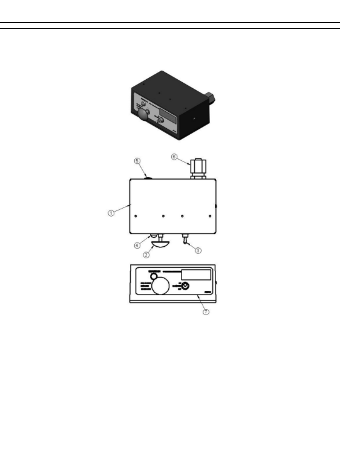
Side Rotary Common Section 6 - 60
SWITCHBOX SERVICE PARTS
ITEM P/N QTY. DESCRIPTION
1 06514013 1 SWBX,ALUM,BLK,06510102
2 35226 1 SWITCH,MOWER,COLEHERSEE
3 33811 1 SWITCH,MASTER/DECK FLOAT
4 6T3923 1 INDICTATOR LIGHT,ON,RED
5 06514014 1 BREAKER,10A,SWBX
6 34540 1 STRAIN RELIEF,3/4,BLACK,NYLON
7 06550018 1 DECAL,SWTCHBX,TM/TSF,CG
8 35227 1 RELAY,DP,DT,12V,LY2F,35226
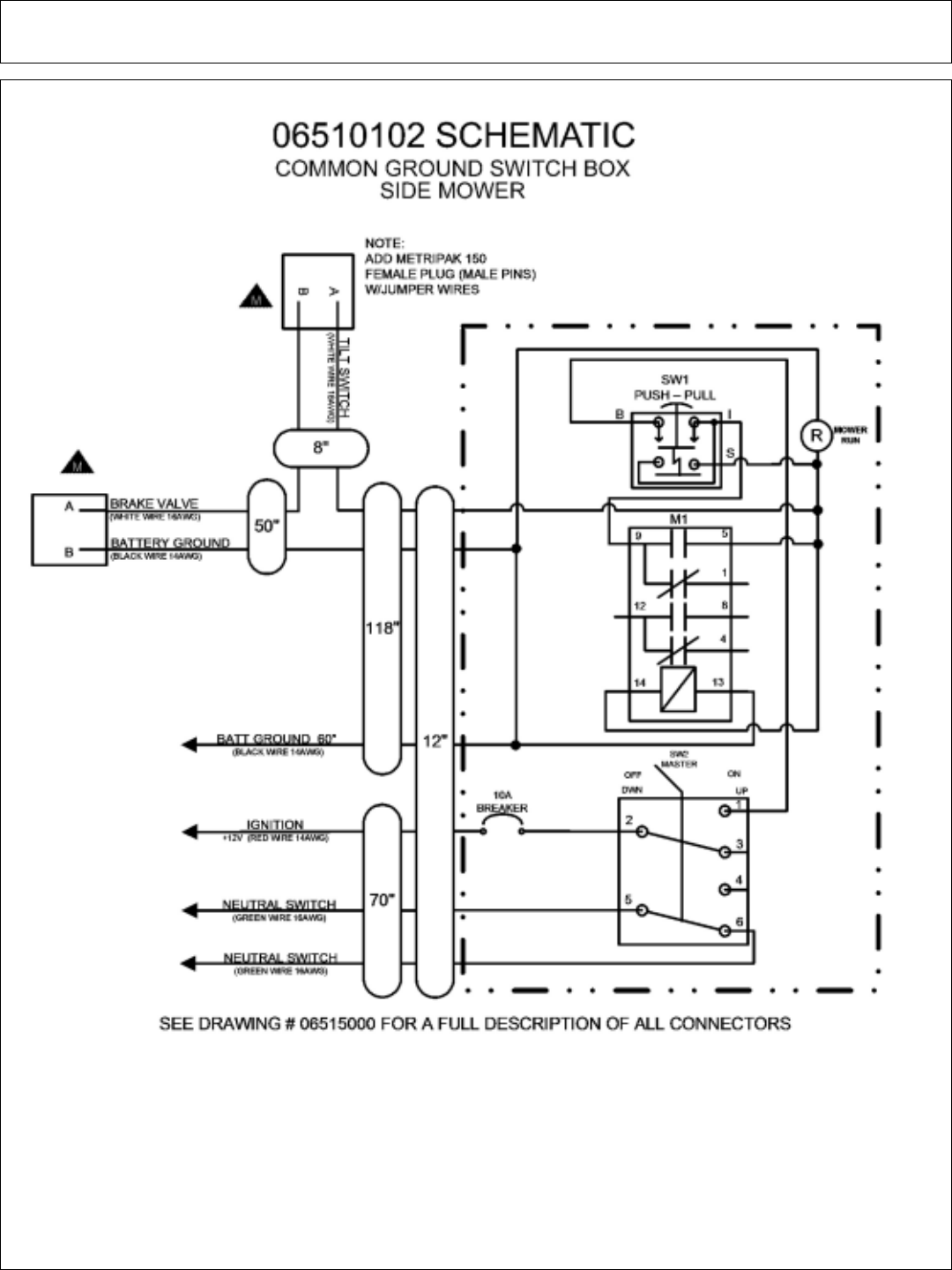
Side Rotary Common Section 6 - 61
SWITCHBOX SCHEMATIC

Side Rotary Common Section 6 - 62

WARRANTY
SECTION
Warranty Section 7-1
.

WARRANTY INFORMATION
Tiger Corporation, 3301 N. Louise, Sioux Falls, South Dakota, warrants to the
original Retail Customer, the new Tiger equipment is free of defects in material and
workmanship. Any part of equipment that in Tiger’s judgement, show evidence of
such defects will be repaired or replaced without charge, provided that the failure of
part(s) shall have occurred within twelve (12) months from the date of delivery of
said equipment to the Retail Customer. Expendable components such as knives,
oil, chain sprockets, skid shoes, knife mounting disks and the like are excluded but
not limited to this warranty.
The Retail Customer must pay the transportation cost to and from the Tiger
Dealer’s service shop for warranty service. Warranty service will be performed by
the Tiger Dealer from whom the equipment was purchased, during service shop
regularly scheduled days and hours of operation.
All Tiger obligation under this warranty shall be terminated if the equipment is
modified or altered in ways not approved in writing by Tiger, if repair parts other than
genuine Tiger repair parts have been used, or if the equipment has been subject to
misuse, neglect, accident, improper maintenance or improper operation.
Tiger Corporation reserves the right to make improvements in design or
changes in specification at any time without incurring any obligation to owners of
equipment previously sold.
No agent or person has authority to alter, add to or waive the above warranties
which are agreed to be in the only warranties, representations or promises,
expressed or implied, as to the quality or performance of the products covered and
which do not include any implied warranty of merchantability or fitness. In no event
will Tiger be liable for incidental or consequential damages or injuries, including, but
not limited to, loss of profits, rental or substitute equipment or other commercial
loss.
THERE ARE NO WARRANTIES WHICH EXTEND
BEYOND THOSE EXPRESSED HEREIN.
It is the Purchasers obligation to sign the warranty registration form AFTER he /
she has Read and Understands the Operation and Safety Instructions stated
within this manual.

ONE LAST WORD
This manual cannot possibly cover all of the
potentially hazardous situations you will
encounter. By being familiar with the
safety rules, operating and maintenance
instructions in this manual you can help prevent
accidents. The objective of this manual is to
help make you a better operator. Remember,
SAFETY IS YOU!
Your safety and the safety of those around you
depends on YOU. Common sense should
play a large role in the operation of this machine.
Since we at Tiger Corporation are constantly striving to improve out products, we
reserve the right to change specifications or design at any time.

TO THE OWNER / OPERATOR / DEALER
To keep your implement running efficiently and safely, read your manual thoroughly and follow
these directions and the Safety Messages in this manual and on the machine. The table of
contents clearly identifies each section where you can easily find the information you need.
The Occupational Safety and Health Act (OSHA 1928.51 subpart C) makes the following
minimum requirements for tractor operators.
OWNER REQUIREMENTS:
1. Provide a Roll-Over-Protective Structure that meets the requirements of this Standard; and
2. Provide Seatbelts that meet the requirements of this Standard and SAE J3C; and
3. Ensure that each employee uses such Seatbelt while the tractor is moving; and
4. Ensure that each employee tightens the Seatbelt sufficiently to confine the employee to the
protected area provided by the ROPS.
OPERATOR REQUIREMENTS:
1. Securely fasten seatbelt it the tractor has a ROPS.
2. Where possible, avoid operating the tractor near steep ditches, embankments, and holes.
3. Reduce speed when turning, crossing slopes, and on rough, slick, or muddy surfaces.
4. Stay off slopes too steep for safe operation.
5. Watch where you are going – especially at row ends, on roads, and around trees.
6. Do Not permit others to ride.
7. Operate the tractor smoothly – no jerky turns, starts, or stops.
8. Hitch only to the draw-bar and hitch points recommended by the tractor manufacturer.
9. When the tractor is stopped, set brakes securely and use park lock, if available

Printed in USA
© Tiger Corporation
