Tippmann C3 Users Manual READERSspreadForPDF
2015-09-01
: Tippmann Tippmann-C3-Users-Manual-804697 tippmann-c3-users-manual-804697 tippmann pdf
Open the PDF directly: View PDF ![]() .
.
Page Count: 14
PN# TP04700 Date: 9/05
Owner’s Manual
Le Manuel du Propriétaire
Manual del Usuario
C3TM
TIPPMANNTM
Back
Cover
Blank
WARNING
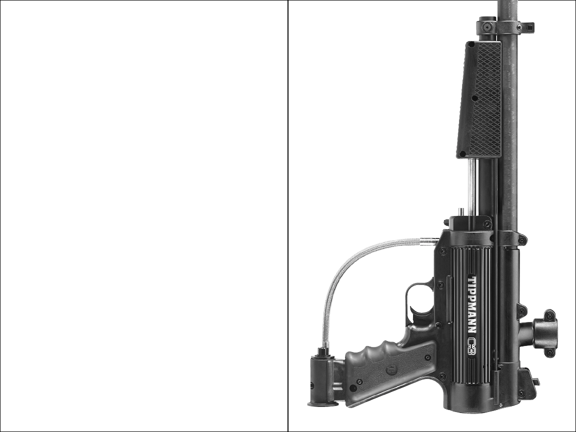
CONGRATULATIONS on your purchase of your TippmannTM
C3TM paintball marker. We believe it to be the most accurate
and durable paintball marker available, and proudly
manufactured in the USA. The TippmannTM C3TM will give many
years of dependable service if cared for properly.
Please take time to read through this manual thoroughly and
become familiar with the TippmannTM C3TM parts, operation, and
safety precautions before you attempt to load or fire this marker.
If you have a missing or broken part or need assistance, please
contact TippmannTM Consumer Relations at 1-800-533-4831
for fast friendly service.
TABLE OF CONTENTS
Warning/Caution ................................................................... 2
Warning/Caution Barrel Sleeve Installation ......................... 2
Warning/Liability Statement .................................................. 4
Safety is your Responsibility................................................. 4
Safe Mode = Turning The Safety On (PUSH SAFE)............. 4
Fire Mode = Turning The Safety Off (PUSH FIRE) ............... 4
Warning/Caution Propane Handling & Storage Instructions 7
Getting Started ...................................................................... 8
1. Installing the Battery ...................................................... 8
2. Propane Supply Cylinder Installation ........................... 8
3. Priming the Marker ........................................................ 8
4. Hopper Installation ........................................................ 9
5. Velocity Adjustment ....................................................... 9
6. To Fire The Marker ........................................................ 9
7. Rear Sight Adjustment................................................... 9
Schematic Parts List ........................................................... 10
Unloading Your Marker ...................................................... 12
Propane Supply Cylinder Removal.................................... 12
Marker / Propane Cylinder Storage.................................... 12
Cleaning & Maintenance .................................................... 12
Marker Disassembly ........................................................... 14
Troubleshooting.................................................................. 20
Specifications ..................................................................... 20
Frequently Asked Questions ............................................... 21
Warranty and Repair Policy ................................................ 23
Warranty or Repair Procedure............................................ 23
Warranty Registration ......................................................... 23
3
2955 Adams Center Road, Fort Wayne, IN 46803 USA
P) 260-749-6022 • F) 260-749-6619
www.tippmann.com
TIPPMANNTM
E
N
G
L
I
S
H
2
E
N
G
L
I
S
H
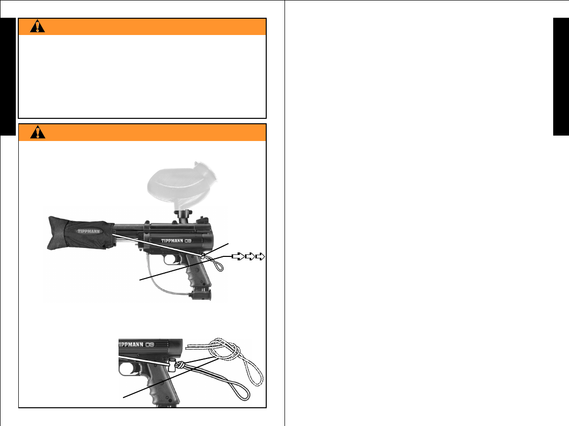
CORD
LENGTH
ADJUSTOR
BUTTON
2) PINCH CORD LENGTH
ADJUSTOR BUTTON AND
HOLD TO BACK OF GRIP AS
YOU PULL CORD THROUGH IT
UNTIL ADJUSTOR IS SNUG
AGAINST BACK OF GRIP,
THEN RELEASE BUTTON.
• EXCEPT WHEN YOUR MARKER IS IN USE, ALWAYS MAKE
SURE THAT THE TRIGGER SAFETY IS IN SAFE MODE (SEE
INSTRUCTIONS ON PAGE 4), AND THE BARREL SLEEVE IS
PROPERLY INSTALLED ON YOUR MARKER AS SHOWN BELOW.
1) SLIDE BARREL INTO SLEEVE AND LOOP CORD OVER TOP
OF RECEIVER AND POSITION AT BACK OF GRIP AS SHOWN
BELOW.
BARREL
SLEEVE
4) AFTER CORD LENGTH
IS ADJUSTED, LOCK
CORD LENGTH BY TYING
A KNOT IN THE CORD
AGAINST THE BACK OF
THE ADJUSTOR AS SHOWN.
BARREL SLEEVE INSTALLATION
WARNING
THIS IS NOT A TOY. MISUSE MAY CAUSE SERIOUS
INJURY OR DEATH. EYE, FACE AND EAR PROTECTION
DESIGNED FOR PAINTBALL MUST BE WORN BY THE
USER AND ANY PERSON WITHIN RANGE. WE
RECOMMEND AT LEAST 18 YEARS OLD TO PURCHASE.
PERSONS UNDER 18 MUST HAVE ADULT SUPERVISION
WHEN USING THIS PRODUCT. READ THE OWNER’S
MANUAL BEFORE USING THIS PRODUCT.
3) CHECK TO BE SURE YOU LEAVE ENOUGH CORD
ELASTICITY TO PULL CORD/ADJUSTOR UP OVER TOP OF
MARKER TO REMOVE BARREL SLEEVE FOR FIRING.
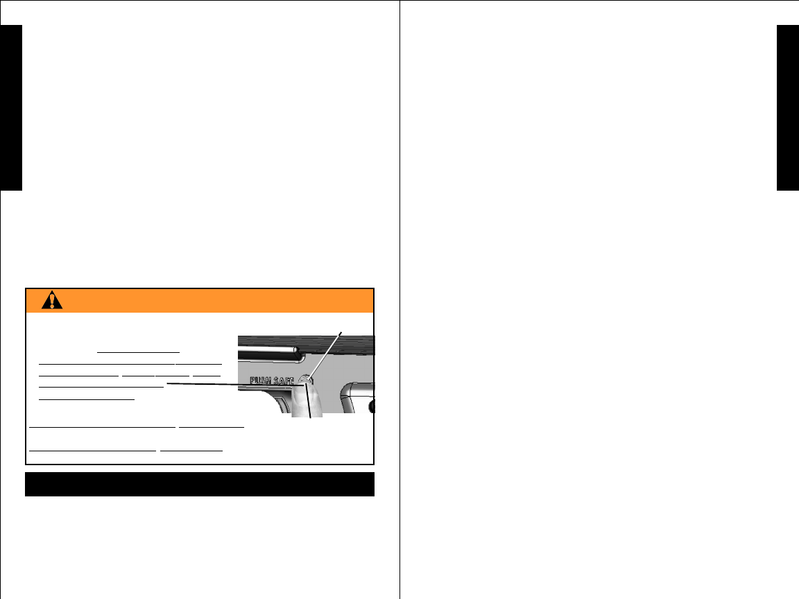
• EXCEPT WHEN YOUR MARKER
IS IN USE, ALWAYS MAKE
SURE THAT THE BARREL SLEEVE
IS INSTALLED (SEE PAGE 2) AND
THE TRIGGER SAFETY
IS IN SAFE MODE WHICH
DISABLES THE TRIGGER.
TO TURN ON THE SAFETY (SAFE MODE): PUSH THE SAFETY
IN AS SHOWN ABOVE.
TO TURN SAFETY OFF (FIRE MODE): PUSH SAME BUTTON
ON OPPOSITE SIDE OF RECEIVER.
safe and sportsmanlike conduct. Always remember that the game
of Paintball can only survive and grow if it remains SAFE!
• Do not load or fire this marker until you have completely read
this manual and are familiar with its safety features,
mechanical operation and handling characteristics.
• Handle this and any marker as if it were loaded at all times.
• Eye, face and ear protection designed specifically to stop
paintballs in the form of approved goggles and full face mask
should be worn by the user and any person within range.
• Never shoot at a person who is not protected by eye, face
and ear protection designed for paintball.
• Pressurize and load the marker only when the marker will be
immediately used.
• Keep your finger off the trigger until ready to shoot.
• Do not look down the barrel of a paintball marker. Accidental
discharge into the eyes may cause permanent injury or death.
• Keep the marker on safe until ready to shoot.
• Keep the barrel sleeve installed on marker when not shooting.
• Never point the marker at anything you do not intend to shoot.
• Never fire your marker at anything you do not intend to shoot
because there may be balls or foreign debris lodged in the
chamber, barrel and / or the marker valve.
• Do not fire at flammable objects as sparks coming from the
barrel could cause a fire.
• Use only in a well ventilated area.
• Do not install or remove cylinder near flames or other ignition
source.
• Keep exposed skin away from escaping gas when installing
or removing propane supply cylinder or if the marker or
propane supply is leaking. Compressed propane gas is very
cold and can cause frostbite under certain conditions.
• Do not inhale propane fumes.
• Other than briefly when attaching or detaching propane
cylinder, if you smell propane - remove the propane cylinder
and seek qualified repair from TippmannTM or your local paintball
dealer. Do not fire the marker if you smell propane.
• Do not shoot at fragile objects such as windows.
• Never fire your marker at personal property of others, the
paintball can stain the paint of automobiles and houses.
• Always keep the muzzle pointed down or in a safe direction,
even if you stumble or fall.
5
Safety Is Your Responsibility (continued from page 4)
Safety Is Your Responsibility
(continued on page 6)
E
N
G
L
I
S
H
Warning/Liability Statement
This marker is classified as a dangerous weapon and is
surrendered by Tippmann Sports, LLC with the understanding
that the purchaser assumes all liability resulting from unsafe
handling or any action that constitutes a violation of any
applicable laws or regulations. Tippmann Sports, LLC shall
not be liable for personal injury, loss of property or life resulting
from the use of this weapon under any circumstances, including
the intentional, reckless, negligent or accidental discharges.
All information contained in this manual is subject to change
without notice. Tippmann Sports, LLC reserves the right to
make changes and improvements to products without incurring
any obligation to incorporate such improvements in products
previously sold.
If you as a user do not accept liability, Tippmann Sports, LLC
requests you do not use a Tippmann Sports, LLC marker. By
using this paintball marker you release Tippmann Sports, LLC
of any and all liability associated with its use.
4
SAFETY IS YOUR RESPONSIBILITY!
The ownership of this weapon places upon you the total
responsibility for its safe and lawful use. You must observe
the same safety precautions as you would any firearm to assure
the safety of not only yourself but everyone around you. The
user should at all times use caution when using this marker.
The sport of Paintball will be viewed and judged upon your
Safety Is Your Responsibility
(continued on page 5)
E
N
G
L
I
S
H
FAMILIARIZE YOURSELF WITH SAFETY...
WARNING
PUSH SAFE
TRIGGER SAFETY ACTIVATION
7
E
N
G
L
I
S
H
Safety Is Your Responsibility (continued from page 6)
• Before storing or disassembling:
1) Remove paintballs from the marker. Completely empty
the hopper, point your marker in a safe direction, fire several
times to be sure there are no balls lodged in the chamber
and/or barrel.
2) Remove the propane supply then pump and fire in a safe
direction until there is no propane left in the marker.
3) Install the barrel sleeve (see page 2) and put safety into the
safe mode (see page 4).
• Store the marker unloaded and degassed in a secure place.
• Do not disassemble this marker while it is pressurized with
propane supply.
• Do not pressurize a partially assembled marker with propane
supply.
• Dress appropriately when playing the game of paintball. Avoid
exposing any skin when playing the game of paintball. Even
a light layer will absorb some of the impact and protect you
from the paintballs.
• Use only .68 caliber paintballs, never load or fire any foreign
objects.
• Avoid alcoholic beverages before and during the use of this
marker. Handling markers while under the influence of drugs
or alcohol is a criminal disregard for public safety.
• Avoid shooting an opponent at point blank, 6 feet or less.
• Always measure your marker’s velocity before playing
paintball and never shoot at velocities in excess of 300 feet
per second (see Velocity Adjustment on page 9).
• Keep barrel clean and dry at all times.
• Familiarize yourself with and follow safe propane cylinder
handling and storage procedures as outlined on the cylinder
label and as follows in the Propane Cylinder Handling and
Storage section on page 7.
6
Safety Is Your Responsibility (continued from page 5)
E
N
G
L
I
S
H
WARNING
FOLLOW HANDLING AND STORAGE INSTRUCTIONS ON
PROPANE CYLINDER IN ADDITION TO THE FOLLOWING.
CARBON MONOXIDE HAZARD:CARBON MONOXIDE HAZARD:
CARBON MONOXIDE HAZARD:CARBON MONOXIDE HAZARD:
CARBON MONOXIDE HAZARD:
BURNING PROPBURNING PROP
BURNING PROPBURNING PROP
BURNING PROPANE CAN MAKE CARBON MONOXIDE WHICH IS INVISIBLE,ANE CAN MAKE CARBON MONOXIDE WHICH IS INVISIBLE,
ANE CAN MAKE CARBON MONOXIDE WHICH IS INVISIBLE,ANE CAN MAKE CARBON MONOXIDE WHICH IS INVISIBLE,
ANE CAN MAKE CARBON MONOXIDE WHICH IS INVISIBLE,
HAS NO SMELLHAS NO SMELL
HAS NO SMELLHAS NO SMELL
HAS NO SMELL
AND CAN KILLAND CAN KILL
AND CAN KILLAND CAN KILL
AND CAN KILL
YOU. BURNING PROPYOU. BURNING PROP
YOU. BURNING PROPYOU. BURNING PROP
YOU. BURNING PROPANE IN ANE IN
ANE IN ANE IN
ANE IN AN ENCLOSEDAN ENCLOSED
AN ENCLOSEDAN ENCLOSED
AN ENCLOSED
AREAAREA
AREAAREA
AREA CAN BE DANGEROUS. USE ONL CAN BE DANGEROUS. USE ONL
CAN BE DANGEROUS. USE ONL CAN BE DANGEROUS. USE ONL
CAN BE DANGEROUS. USE ONLYY
YY
Y IN WELL-VENTILA IN WELL-VENTILA
IN WELL-VENTILA IN WELL-VENTILA
IN WELL-VENTILATED TED
TED TED
TED AREAS. IFAREAS. IF
AREAS. IFAREAS. IF
AREAS. IF
YOU EXPERIENCE HEADACHE, DROWSINESS, OR NAUSEA, STOP USINGYOU EXPERIENCE HEADACHE, DROWSINESS, OR NAUSEA, STOP USING
YOU EXPERIENCE HEADACHE, DROWSINESS, OR NAUSEA, STOP USINGYOU EXPERIENCE HEADACHE, DROWSINESS, OR NAUSEA, STOP USING
YOU EXPERIENCE HEADACHE, DROWSINESS, OR NAUSEA, STOP USING
THE MARKER THE MARKER
THE MARKER THE MARKER
THE MARKER AND GETAND GET
AND GETAND GET
AND GET FRESH FRESH
FRESH FRESH
FRESH AIR QUICKLAIR QUICKL
AIR QUICKLAIR QUICKL
AIR QUICKLYY
YY
Y..
..
.
PROPPROP
PROPPROP
PROPANE CYLINDER HANDLING ANE CYLINDER HANDLING
ANE CYLINDER HANDLING ANE CYLINDER HANDLING
ANE CYLINDER HANDLING AND STAND ST
AND STAND ST
AND STORAGE:ORAGE:
ORAGE:ORAGE:
ORAGE:
1.1.
1.1.
1. KEEP OUT OF REACH OF CHILDREN.KEEP OUT OF REACH OF CHILDREN.
KEEP OUT OF REACH OF CHILDREN.KEEP OUT OF REACH OF CHILDREN.
KEEP OUT OF REACH OF CHILDREN.
2.2.
2.2.
2. DO NOTDO NOT
DO NOTDO NOT
DO NOT EXPOSE EXPOSE
EXPOSE EXPOSE
EXPOSE TT
TT
TO HEAO HEA
O HEAO HEA
O HEATT
TT
T, SP, SP
, SP, SP
, SPARKS, OR FLAME.ARKS, OR FLAME.
ARKS, OR FLAME.ARKS, OR FLAME.
ARKS, OR FLAME.
DO NOTDO NOT
DO NOTDO NOT
DO NOT LEA LEA
LEA LEA
LEAVE IN DIRECTVE IN DIRECT
VE IN DIRECTVE IN DIRECT
VE IN DIRECT SUNLIGHT SUNLIGHT
SUNLIGHT SUNLIGHT
SUNLIGHT..
..
.
DO NOTDO NOT
DO NOTDO NOT
DO NOT ST ST
ST ST
STORE ORE
ORE ORE
ORE AA
AA
ATT
TT
T
TEMPERATEMPERA
TEMPERATEMPERA
TEMPERATURES TURES
TURES TURES
TURES ABOVE 120ABOVE 120
ABOVE 120ABOVE 120
ABOVE 120OO
OO
O F F
F F
F
..
..
.
3.3.
3.3.
3. NEVER STNEVER ST
NEVER STNEVER ST
NEVER STORE IN LIVING SPORE IN LIVING SP
ORE IN LIVING SPORE IN LIVING SP
ORE IN LIVING SPACES.ACES.
ACES.ACES.
ACES.
4.4.
4.4.
4. NEVER REFILLNEVER REFILL
NEVER REFILLNEVER REFILL
NEVER REFILL
AA
AA
A PROP PROP
PROP PROP
PROPANE CYLINDER. REFILLING MAANE CYLINDER. REFILLING MA
ANE CYLINDER. REFILLING MAANE CYLINDER. REFILLING MA
ANE CYLINDER. REFILLING MAYY
YY
Y CAUSE CAUSE
CAUSE CAUSE
CAUSE
EXPLOSION.EXPLOSION.
EXPLOSION.EXPLOSION.
EXPLOSION.
FEDERALFEDERAL
FEDERALFEDERAL
FEDERAL LA LA
LA LA
LAW FORBIDW FORBID
W FORBIDW FORBID
W FORBIDS S
S S
S TRTR
TRTR
TRANSPORANSPOR
ANSPORANSPOR
ANSPORTT
TT
TAA
AA
ATIONTION
TIONTION
TION IF REFILLED- IF REFILLED-
IF REFILLED- IF REFILLED-
IF REFILLED-
PENALPENAL
PENALPENAL
PENALTYTY
TYTY
TY UP UP
UP UP
UP
TT
TT
TO $500,000 O $500,000
O $500,000 O $500,000
O $500,000 AND 5 AND 5
AND 5 AND 5
AND 5 YEARS IMPRISONMENTYEARS IMPRISONMENT
YEARS IMPRISONMENTYEARS IMPRISONMENT
YEARS IMPRISONMENT. (49 U.S.C. 5124).. (49 U.S.C. 5124).
. (49 U.S.C. 5124).. (49 U.S.C. 5124).
. (49 U.S.C. 5124).
5.5.
5.5.
5. NEVER PUTNEVER PUT
NEVER PUTNEVER PUT
NEVER PUT IN LUGGAGE OR IN LUGGAGE OR
IN LUGGAGE OR IN LUGGAGE OR
IN LUGGAGE OR TT
TT
TAKE ON AKE ON
AKE ON AKE ON
AKE ON TRAINS OR TRAINS OR
TRAINS OR TRAINS OR
TRAINS OR AIRCRAFTAIRCRAFT
AIRCRAFTAIRCRAFT
AIRCRAFT..
..
.
6.6.
6.6.
6. TT
TT
TO DISCARD, CONTO DISCARD, CONT
O DISCARD, CONTO DISCARD, CONT
O DISCARD, CONTACTACT
ACTACT
ACT LOCAL LOCAL
LOCAL LOCAL
LOCAL REFUSE HAULER OR RECYCLE REFUSE HAULER OR RECYCLE
REFUSE HAULER OR RECYCLE REFUSE HAULER OR RECYCLE
REFUSE HAULER OR RECYCLE
CENTER. NEVER PUTCENTER. NEVER PUT
CENTER. NEVER PUTCENTER. NEVER PUT
CENTER. NEVER PUT IN FIRE OR INCINERA IN FIRE OR INCINERA
IN FIRE OR INCINERA IN FIRE OR INCINERA
IN FIRE OR INCINERATT
TT
TOR. DO NOTOR. DO NOT
OR. DO NOTOR. DO NOT
OR. DO NOT PUNCTURE. PUNCTURE.
PUNCTURE. PUNCTURE.
PUNCTURE.
FIRE / EXPLOSION HAZARD: EVEN SMALLFIRE / EXPLOSION HAZARD: EVEN SMALL
FIRE / EXPLOSION HAZARD: EVEN SMALLFIRE / EXPLOSION HAZARD: EVEN SMALL
FIRE / EXPLOSION HAZARD: EVEN SMALL PROP PROP
PROP PROP
PROPANE CYLINDERSANE CYLINDERS
ANE CYLINDERSANE CYLINDERS
ANE CYLINDERS
CONTCONT
CONTCONT
CONTAIN ENOUGH GAS AIN ENOUGH GAS
AIN ENOUGH GAS AIN ENOUGH GAS
AIN ENOUGH GAS TT
TT
TO CAUSE SERIOUS FIRE, EXPLOSION, O CAUSE SERIOUS FIRE, EXPLOSION,
O CAUSE SERIOUS FIRE, EXPLOSION, O CAUSE SERIOUS FIRE, EXPLOSION,
O CAUSE SERIOUS FIRE, EXPLOSION, ANDAND
ANDAND
AND
BURNS. TO REDUCE CHANCE OF LIQUID OR GAS LEAK, OR EXPLOSION:BURNS. TO REDUCE CHANCE OF LIQUID OR GAS LEAK, OR EXPLOSION:
BURNS. TO REDUCE CHANCE OF LIQUID OR GAS LEAK, OR EXPLOSION:BURNS. TO REDUCE CHANCE OF LIQUID OR GAS LEAK, OR EXPLOSION:
BURNS. TO REDUCE CHANCE OF LIQUID OR GAS LEAK, OR EXPLOSION:
BEFORE USE:BEFORE USE:
BEFORE USE:BEFORE USE:
BEFORE USE:
1.1.
1.1.
1. CHECK CYLINDER AND MARKER SEALS. NEVER USE WITH DAMAGEDCHECK CYLINDER AND MARKER SEALS. NEVER USE WITH DAMAGED
CHECK CYLINDER AND MARKER SEALS. NEVER USE WITH DAMAGEDCHECK CYLINDER AND MARKER SEALS. NEVER USE WITH DAMAGED
CHECK CYLINDER AND MARKER SEALS. NEVER USE WITH DAMAGED
OR MISSING SEALS. DISCARD CYLINDER IF DIROR MISSING SEALS. DISCARD CYLINDER IF DIR
OR MISSING SEALS. DISCARD CYLINDER IF DIROR MISSING SEALS. DISCARD CYLINDER IF DIR
OR MISSING SEALS. DISCARD CYLINDER IF DIRTT
TT
T OR RUST OR RUST
OR RUST OR RUST
OR RUST P P
P P
P
ARAR
ARAR
ARTICLESTICLES
TICLESTICLES
TICLES
ARE IN VARE IN V
ARE IN VARE IN V
ARE IN VALAL
ALAL
ALVE VE
VE VE
VE AREA.AREA.
AREA.AREA.
AREA.
2.2.
2.2.
2. HOLD CYLINDER UPRIGHTHOLD CYLINDER UPRIGHT
HOLD CYLINDER UPRIGHTHOLD CYLINDER UPRIGHT
HOLD CYLINDER UPRIGHT WHILE WHILE
WHILE WHILE
WHILE AA
AA
ATTTT
TTTT
TTACHING.ACHING.
ACHING.ACHING.
ACHING.
3.3.
3.3.
3. AA
AA
ATTTT
TTTT
TTACH OUTDOORS ACH OUTDOORS
ACH OUTDOORS ACH OUTDOORS
ACH OUTDOORS AA
AA
AWW
WW
WAA
AA
AYY
YY
Y FROM PILOT FROM PILOT
FROM PILOT FROM PILOT
FROM PILOT LIGHTS, FLAMES, SP LIGHTS, FLAMES, SP
LIGHTS, FLAMES, SP LIGHTS, FLAMES, SP
LIGHTS, FLAMES, SPARKS, ORARKS, OR
ARKS, ORARKS, OR
ARKS, OR
OTHER IGNITION SOURCES. THEY CAN IGNITE LEAKING GAS.OTHER IGNITION SOURCES. THEY CAN IGNITE LEAKING GAS.
OTHER IGNITION SOURCES. THEY CAN IGNITE LEAKING GAS.OTHER IGNITION SOURCES. THEY CAN IGNITE LEAKING GAS.
OTHER IGNITION SOURCES. THEY CAN IGNITE LEAKING GAS.
4.4.
4.4.
4. HAND HAND
HAND HAND
HAND TIGHTEN ONLTIGHTEN ONL
TIGHTEN ONLTIGHTEN ONL
TIGHTEN ONLYY
YY
Y. OVER. OVER
. OVER. OVER
. OVERTIGHTENING MATIGHTENING MA
TIGHTENING MATIGHTENING MA
TIGHTENING MAYY
YY
Y DAMAGE SEALS. NEVER DAMAGE SEALS. NEVER
DAMAGE SEALS. NEVER DAMAGE SEALS. NEVER
DAMAGE SEALS. NEVER
USE TOOLS TO TIGHTEN.USE TOOLS TO TIGHTEN.
USE TOOLS TO TIGHTEN.USE TOOLS TO TIGHTEN.
USE TOOLS TO TIGHTEN.
5.5.
5.5.
5. CHECK FOR LEAKS IN ONE OR MORE WCHECK FOR LEAKS IN ONE OR MORE W
CHECK FOR LEAKS IN ONE OR MORE WCHECK FOR LEAKS IN ONE OR MORE W
CHECK FOR LEAKS IN ONE OR MORE WAA
AA
AYS: YS:
YS: YS:
YS: APPLAPPL
APPLAPPL
APPLYY
YY
Y SOAPY SOAPY
SOAPY SOAPY
SOAPY W W
W W
WAA
AA
ATER TER
TER TER
TER TT
TT
TOO
OO
O
CONNECTIONS. LOOK FOR BUBBLES. LISTEN FOR HISS OF ESCAPINGCONNECTIONS. LOOK FOR BUBBLES. LISTEN FOR HISS OF ESCAPING
CONNECTIONS. LOOK FOR BUBBLES. LISTEN FOR HISS OF ESCAPINGCONNECTIONS. LOOK FOR BUBBLES. LISTEN FOR HISS OF ESCAPING
CONNECTIONS. LOOK FOR BUBBLES. LISTEN FOR HISS OF ESCAPING
GAS. FEEL FOR EXTREME COLD. SMELL FOR ROTTEN EGG ODOR.GAS. FEEL FOR EXTREME COLD. SMELL FOR ROTTEN EGG ODOR.
GAS. FEEL FOR EXTREME COLD. SMELL FOR ROTTEN EGG ODOR.GAS. FEEL FOR EXTREME COLD. SMELL FOR ROTTEN EGG ODOR.
GAS. FEEL FOR EXTREME COLD. SMELL FOR ROTTEN EGG ODOR.
DO NOT USE IF LEAKING.DO NOT USE IF LEAKING.
DO NOT USE IF LEAKING.DO NOT USE IF LEAKING.
DO NOT USE IF LEAKING.
AFTER USE:AFTER USE:
AFTER USE:AFTER USE:
AFTER USE:
1.1.
1.1.
1. LETLET
LETLET
LET MARKER COOL MARKER COOL
MARKER COOL MARKER COOL
MARKER COOL OFF OFF
OFF OFF
OFF..
..
.
2.2.
2.2.
2. DETDET
DETDET
DETACH CYLINDER WHEN NOTACH CYLINDER WHEN NOT
ACH CYLINDER WHEN NOTACH CYLINDER WHEN NOT
ACH CYLINDER WHEN NOT IN USE. IN USE.
IN USE. IN USE.
IN USE.
3.3.
3.3.
3. DETDET
DETDET
DETACH OUTDOORS ACH OUTDOORS
ACH OUTDOORS ACH OUTDOORS
ACH OUTDOORS AA
AA
AWW
WW
WAA
AA
AYY
YY
Y FROM PILOT FROM PILOT
FROM PILOT FROM PILOT
FROM PILOT LIGHTS, FLAMES, SP LIGHTS, FLAMES, SP
LIGHTS, FLAMES, SP LIGHTS, FLAMES, SP
LIGHTS, FLAMES, SPARKS, ORARKS, OR
ARKS, ORARKS, OR
ARKS, OR
OTHER IGNITION SOURCES. THEY CAN IGNITE LEAKING GAS.OTHER IGNITION SOURCES. THEY CAN IGNITE LEAKING GAS.
OTHER IGNITION SOURCES. THEY CAN IGNITE LEAKING GAS.OTHER IGNITION SOURCES. THEY CAN IGNITE LEAKING GAS.
OTHER IGNITION SOURCES. THEY CAN IGNITE LEAKING GAS.
4.4.
4.4.
4. REPLACE CYLINDER CAPREPLACE CYLINDER CAP
REPLACE CYLINDER CAPREPLACE CYLINDER CAP
REPLACE CYLINDER CAP
TT
TT
TO KEEPO KEEP
O KEEPO KEEP
O KEEP V V
V V
V
ALAL
ALAL
ALVE CLEAN.VE CLEAN.
VE CLEAN.VE CLEAN.
VE CLEAN.
IN CASE OF FIRE:IN CASE OF FIRE:
IN CASE OF FIRE:IN CASE OF FIRE:
IN CASE OF FIRE:
1.1.
1.1.
1.
LEALEA
LEALEA
LEAVE VE
VE VE
VE AREAAREA
AREAAREA
AREA QUICKL QUICKL
QUICKL QUICKL
QUICKLYY
YY
Y. 2. CALL. 2. CALL
. 2. CALL. 2. CALL
. 2. CALL FOR EMERGENCY FOR EMERGENCY
FOR EMERGENCY FOR EMERGENCY
FOR EMERGENCY HELP HELP
HELP HELP
HELP. 3. LET. 3. LET
. 3. LET. 3. LET
. 3. LET
CYLINDER BURN OUTCYLINDER BURN OUT
CYLINDER BURN OUTCYLINDER BURN OUT
CYLINDER BURN OUT..
..
.
Safety Is Your Responsibility
(continued on page 7)
Propane Cylinder Handling and Storage
STEP 4: Hopper Installation
Barrel Sleeve must be installed (see page 2) and safety in
Safe Mode (see page 4) before filling the hopper.
• Make sure that the feed elbow and hopper are clean and
free of any sharp edges to keep paintballs feeding into the
marker properly.
• Install the hopper neck into the feed elbow of your marker
and tighten the hopper down with a 1/8” allen wrench.
NOTE: Do not overtighten or the elbow may break. With the
barrel sleeve installed and safety in Safe Mode, you are now
ready to load your hopper with paintballs. Fill hopper and only
remove barrel sleeve and turn off the safety when ready to shoot.
89
E
N
G
L
I
S
H
E
N
G
L
I
S
H
STEP 1: Installing / Replacing the Battery
This marker needs a good battery to operate. If your battery is
low or dead install a new battery before installing the propane
supply cylinder in STEP 2. To install the AAA battery:
• Do not pressurize a partially assembled paintball marker.
• Make sure marker is unloaded (see page 12).
• Install barrel sleeve (see instructions on page 2).
• Put trigger safety in Safe Mode (see instructions on page 4).
• Remove the 2 screws holding the left grip in place.
• To remove the battery, pull up on the free end of the ribbon
positioned under the battery to lift it out.
• To install battery first lay ribbon across battery holder keeping
loose end free. Next insert new AAA battery on top of ribbon
and into the ignition module battery holder, keeping the
positive (+) end towards the top of the marker.
• Replace left grip and secure with 2 screws to complete
battery installation.
STEP 2: Propane Supply Cylinder Installation
• Do not pressurize a partially assembled paintball marker.
• First install barrel sleeve (see instructions on page 2).
• Next put trigger safety in Safe Mode (see instructions on page 4).
• Hold cylinder upright while attaching. Insert the cylinder valve
end into the regulator and twist cylinder clockwise until it stops.
• Listen and smell for propane leaks, do not fire if leaking.
STEP 3: Priming The Marker:
After any tank installation,
before loading the marker with
paintballs
, you must prime the marker. First remove the barrel
sleeve and turn the safety off. NOTE: Sliding the Forearm Grip
completely to the back position clears the exhaust from the
combustion chamber and allows a paintball to load if there are
paintballs in the hopper / sliding the forearm grip completely to
the forward position fills the combustion chamber with air for
next shot and chambers a paintball if there are paintballs in the
hopper. It is important to make complete pump strokes in order
for the marker to fire properly. Pump and fire the marker in a safe
direction several times until it starts shooting. Reinstall barrel
sleeve and put trigger safety in Safe Mode.
NOTE: Over time as the internal parts of the Regulator break-in
or if the unit has been disassembled for service, the marker
Do not proceed until you haveDo not proceed until you have
Do not proceed until you haveDo not proceed until you have
Do not proceed until you have
both familiarized yourself withboth familiarized yourself with
both familiarized yourself withboth familiarized yourself with
both familiarized yourself with
and are prepared to alwaysand are prepared to always
and are prepared to alwaysand are prepared to always
and are prepared to always
follow guidelines for properfollow guidelines for proper
follow guidelines for properfollow guidelines for proper
follow guidelines for proper
propane cylinder and markerpropane cylinder and marker
propane cylinder and markerpropane cylinder and marker
propane cylinder and marker
handling and storage.handling and storage.
handling and storage.handling and storage.
handling and storage.
GETTING STARTED
Priming The Marker (continued on page 9)
Priming The Marker (continued from page 8)
STEP 5: To Fire The Marker
It is important to make complete pump strokes in order for the
marker to fire properly. Sliding the Forearm Grip completely
back and then sliding it completely forward = 1 Pump. Pump 1
time and pull the trigger to fire 1 shot. Do not pump more than
1 time for each shot which would cause the marker to load
more than 1 paintball and could break a ball in the chamber.
NOTE: It is normal for the marker to become very warm when
shooting.
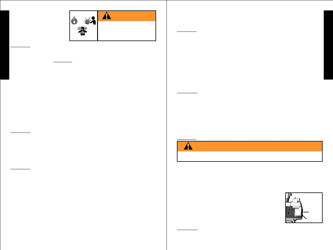
WARNING
STEP 6: Velocity Adjustment
DO NOT TURN THE VELOCITY ADJUSTMENT SCREW OUT
SO FAR THAT IT PUSHES AGAINST THE END CAP.
Velocity
Adjustment
Screw
Access
To adjust the velocity up, insert a large flat
head screwdriver through the end cap and into
the large velocity screw slot and turn it inward
or clockwise.
STEP 7: Rear Sight Adjustment
If your paintball is hitting low, slide the rear sight back towards
rear of marker. Do the opposite if paintball is hitting high.
•
EXTREMELEXTREMEL
EXTREMELEXTREMEL
EXTREMELYY
YY
Y FLAMMABLE FLAMMABLE
FLAMMABLE FLAMMABLE
FLAMMABLE
•
FIRE/EXPLOSION HAZARDFIRE/EXPLOSION HAZARD
FIRE/EXPLOSION HAZARDFIRE/EXPLOSION HAZARD
FIRE/EXPLOSION HAZARD
•
CONTENTS UNDER PRESSURECONTENTS UNDER PRESSURE
CONTENTS UNDER PRESSURECONTENTS UNDER PRESSURE
CONTENTS UNDER PRESSURE
•
CARBON MONOXIDE HAZZARDCARBON MONOXIDE HAZZARD
CARBON MONOXIDE HAZZARDCARBON MONOXIDE HAZZARD
CARBON MONOXIDE HAZZARD
DANGER
Each time you play paintball, the velocity of your paintball
marker should be checked with a chronograph, an instrument
for measuring velocity, prior to playing paintball to verify that
the marker’s velocity is set below 300 feet per second or less
if required by playing field.
To turn the velocity down, turn it out or
counterclockwise - do not turn it out far enough
that it pushes against the inside of the end cap.
End Cap
may cease to fire during the priming procedure because the
air/fuel mixture needs adjustment. To adjust the air/fuel mixture,
follow the Regulator Adjustment instructions on page 14.
11
E
N
G
L
I
S
H
10
E
N
G
L
I
S
H
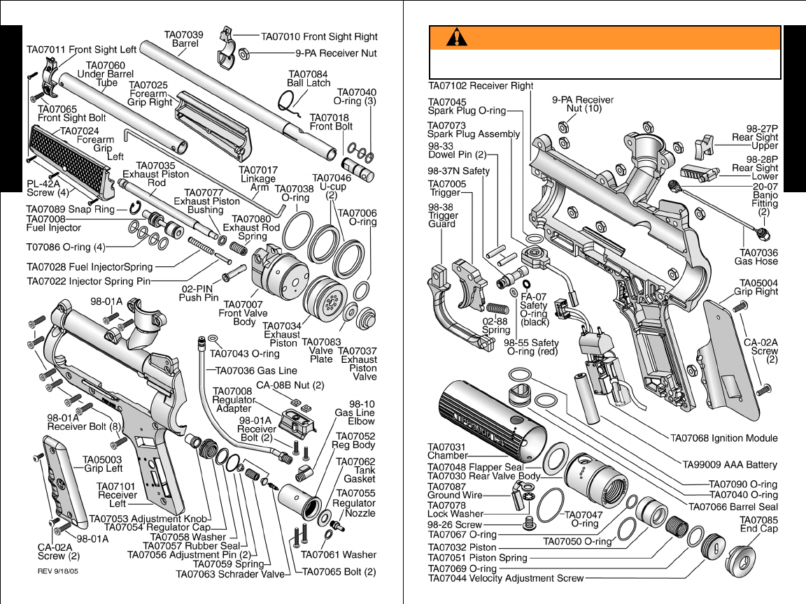
WARNING
DO NOT DISASSEMBLE THIS MARKER WHILE IT IS PRESSURIZED WITH
PROPANE. DO NOT PRESSURIZE A PARTIALLY ASSEMBLED MARKER.
C3TM Parts List
TIPPMANNTM
1-800-533-4831
www.tippmann.com

13
E
N
G
L
I
S
H
Rear Valve / Piston Cleaning
(continued on page 14)
Unloading Your Marker
Before storing or disassembling be sure to remove paintballs
and propane supply.
• To unload your marker: remove or completely empty the
hopper. Then, point your marker in a safe direction and fire
several times to be sure there are no balls lodged in the
chamber and / or barrel.
•Propane Supply Cylinder Removal: To remove a propane
supply cylinder, turn the cylinder counterclockwise or out.
This allows the propane supply pin valve to close so that no
propane will enter the marker. After the cylinder is removed,
point the marker in a safe direction then pump/fire several
times to make sure there is no propane left in the marker.
• Install barrel sleeve (see page 2) and put trigger safety in Safe
Mode (see instructions on page 4).
Marker / Propane Cylinder Storage
Before storage, unload paintballs and remove propane supply
(see above). Then install Barrel Sleeve (see page 2) and put
your marker in Safe Mode (see page 4). You should store your
marker in a dry area. Before storing your marker make sure
that the marker is cleaned and oiled (see cleaning and
maintenance below) to ensure optimum performance and long
life. Store propane cylinder as outlined in Propane Cylinder
Handling and Storage section on page 7.
When removing your marker out of storage, make sure Barrel
Sleeve is installed (see page 2) and safety is in Safe Mode
(see page 4).
Marker Cleaning and Maintenance
To reduce the chance of accidental discharge: First follow
unloading and propane supply removal instructions (above)
and never disassemble a marker that is under pressure.
• Do not pressurize a partially assembled paintball marker.
• Do not disassemble a marker until it has cooled to room
temperature as internal parts may be extremely hot.
• Follow warnings listed on the propane supply cylinder for
handling and storage.
• Familiarize yourself with instructions listed on propane supply
cylinder and review the Propane Cylinder Handling and
Storage instructions on page 7.
• To clean the exterior of your paintball marker use a damp
towel with water to wipe off paint, oil, and debris. We
recommend using TippmannTM marker oil or other premium
12
Cleaning and Maintenance (continued from page 12)
Cleaning and Maintenance
(continued on page 13)
E
N
G
L
I
S
H
gun oil to maintain your marker in good working condition.
Re-oil when necessary.
•Barrel Cleaning: It is important to clean the barrel whenever
you break a paintball. Residue in barrel can burn causing
smoke, more ball breakage and poor performance. It is
not necessary to remove the barrel from marker to clean it.
To clean the barrel: use the special cleaning squeegee that
came with your C3TM marker. Move forearm grip to the rear
position. Press squeegee button to tilt squeegee flat, then
while holding in flat position, insert squeegee completely into
barrel and release button. Pull squeegee out of barrel to
remove debris. Next insert opposite end of cleaning
squeegee to swab the barrel. Repeat as necessary.
•Spark Plug Cleaning: If the spark plug becomes dirty or oily
it may cause the marker to misfire and may cause the
electronics to short out. To clean the Spark Plug:
1) Follow the Unloading The Marker instructions on page 12.
2) Follow the Propane Supply Cylinder Removal instructions
on page 12.
3) Follow the Disassembling the Marker instructions
beginning on page 14.
4) After you remove the Spark Plug, use a cloth to wipe it clean.
Any time the receiver is disassembled clean the Spark Plug.
•Rear Valve / Piston Cleaning: It is important to periodically
clean the Rear Valve and Piston to maintain marker
performance. This cleaning can be performed without
extensive disassembly of the marker.
1) Complete the Unloading The Marker instructions on page 12.
2) Complete the Propane Supply Cylinder Removal instructions
on page 12.
3) With steps 1 and 2 completed proceed as follows:
a) Carefully pull the End Cap from the end of the receiver.
b) Remove the Velocity Adjustment Screw by turning it
counterclockwise with a large flat head screwdriver, then
remove the spring and buffer o-ring.
c) Pull the piston out the back of the marker.
d) Clean the piston with WD-40 and wipe clean. Inspect
the two piston o-rings for wear and replace if necessary.
e) Clean the Rear Valve internal surfaces with WD-40
and wipe clean.
f) Lubricate the Piston o-rings with TippmannTM Marker oil
or other premium marker oil and insert the Piston into
the Rear Valve (closed end of piston goes in first).
g) Insert the spring and buffer o-ring.
DISASSEMBLING YOUR MARKER:
Refer to schematic parts listing pages for additional part
identification as necessary.
1) Unload The Marker (see instructions page 12).
2) Remove Propane Supply Cylinder (see instructions page 12).
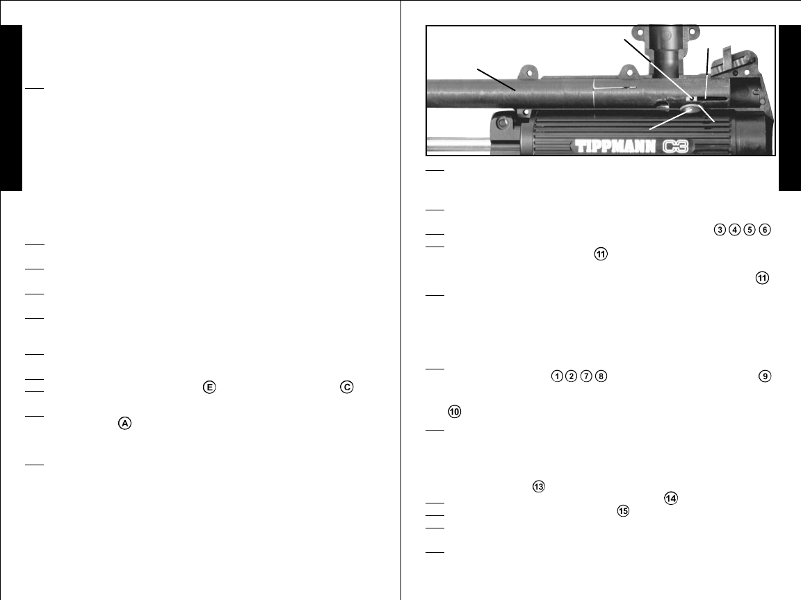
3) Barrel Removal: NOTE: When reinstalling the barrel you will
want to align it correctly with the feed elbow so the paintballs
will load properly from the feed elbow into the barrel. Before
removing the barrel and after completing Step 1) and 2) above,
you can check what a proper alignment feels like by pumping
the forearm grip back and then inserting your finger into the
feed elbow to feel where the barrel hole and feeder hole fit
together - when correctly aligned, this will be a smooth transition.
During installation this is how it should feel.
• Loosen receiver bolt , remove push pin , and then slide
front sight/under barrel tube as one piece out of the receiver. 15
E
N
G
L
I
S
H
Receiver Disassembly
(continued on page 16)
14
E
N
G
L
I
S
H
Rear Valve / Piston Cleaning (continued from page 13)
Barrel Removal (continued on page 15)
• Slide barrel forward a little bit , until you can remove the
Linkage Arm from the Rear Bolt in the back end of barrel .
Remove Linkage Arm from forearm grip. Pull the barrel out of
the receiver. Next remove the Front Bolt from the back of the
barrel and clean barrel and Front Bolt with water and wipe dry.
Inspect and oil front bolt o-rings (replace if necessary). Install
front bolt back into barrel being careful that bolt end with hole
for linkage arm goes in last and hole aligns with the slot on side
of the barrel (see Barrel Insertion page 19).
You may reassemble the barrel at this time in the reverse
order making sure that the ball hole lines up well with the
feed elbow or continue with receiver disassembly.
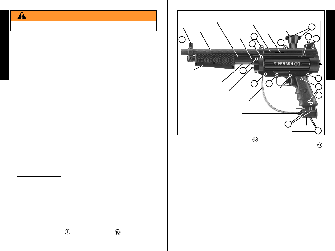
End Cap
Front
Sight
Barrel Under
Barrel
Tube
Left
Receiver
Half Ball
Latch Feed
Elbow
Linkage
Arm
Gas Line
Exhaust Piston Rod
Fuel Injector Left Grip
Regulator Bolts (2)
Regulator
Adapter
Left Forearm Grip
13
10
1
28
9
11
Regulator Adapter Bolts (2)
(not visible until regulator removed) Regulator
6
7
34
5
15
12
Velocity Adjustment Screw
14
Regulator Adjustment Knob
h) Carefully screw the Velocity Screw into the Rear Valve
until at least flush
with the end of the Rear Valve body and
then replace the End Cap. Cleaning is complete.
You will need to adjust velocity as outlined on page 9.
WARNING
FIRING YOUR MARKER WITHOUT THE VELOCITY SCREW INSTALLED CAN
CAUSE THE PISTON TO BE EJECTED FROM THE REAR OF THE MARKER.
Regulator Adjustment: Make sure there are no paintballs in
your marker and hopper when you adjust the regulator.
• The regulator controls the air/fuel mixture and the marker will
not fire if the mixture is too rich or too lean. It is set at the
factory for best performance. This setting may need to be
adjusted over time as the internal parts break-in or if the unit
has been disassembled for service.
• The regulator adjustment knob is located at the front of the
regulator body and is adjusted as follows:
1) Turn the adjustment knob clockwise all the way with a 3/16”
allen wrench to completely shut off the flow of gas.
2) Turn the adjustment knob 1/2 turn counterclockwise; pump
the marker several times and attempt to fire in a safe direction.
Repeat this process until the marker fires for the first time -
then go 1/2 turn further. This setting should offer the best
performance (The range between too rich and too lean is
approximately one full turn - the ideal setting is half way
between).
Receiver Disassembly:
•Fuel injector removal: Remove c-clip holding it inside of the
front of Front Valve Body, remove the fuel injector, spring and
spring pin and clean them. Clean, inspect and oil the 4 o-
rings (replace if necessary). Put spring on pin and insert into
fuel injector. Insert pin/spring end first into front valve body
and secure with c-clip (see schematic page 10).
Safety
Barrel Removal (continued from page 14)
Chamber Disassembly (continued from page 16)
Chamber Disassembly
(continued on page 18)
17
E
N
G
L
I
S
H
16
E
N
G
L
I
S
H
5) Battery Removal: Remove the 2 Left Grip screws , the Left
Grip and pull up loose end of ribbon under the Battery to pop it out.
6) Pull the end cap out of the receiver.
7) Remove the Regulator - 2 bolts at .
8) Remove the Regulator Adapter - 2 bolts at .
9) Remove the 2 Banjo Fittings and Gas Hose
as 1 piece from the right side of the marker.
Clean and inspect the o-ring on each Banjo Fitting for wear
and oil (replace if necessary).
10) Remove the 8 Receiver Bolts , and
the two Feeder Bolts , holding the receiver halves together.
11) Carefully lift the Left Receiver Half off of the marker. Trigger
pins and electronics should all remain in Right Receiver Half.
IMPORTANT: The top Barrel Seal O-ring fits onto top of barrel
seal/chamber (as shown on next page). You will need to be
sure the o-ring is positioned like this when you reinstall the
barrel during reassembly.
12) Lift the left end of the Chamber just enough to remove the
gas line and then lift the Spark Plug out of slot in the right
receiver and unplug it from the ignition module. Use a cloth
to wipe the Spark Plug clean. Any time you have the receiver
disassembled to this point, clean the Spark Plug.
NOTE: If you are disassembling marker just to clean the Spark
Plug, it is not necessary to disassemble marker any further;
install Spark Plug back into slot in right receiver half and plug
back into ignition module. Skip to Step 23 and follow marker
reassembly instructions.
Chamber Disassembly
(continued on page 17)
Receiver Disassembly (continued from page 15)
Chamber Removal And Disassembly
13) Carefully lift the Chamber assembly enough to unplug
the ground wire from the ignition module and then lift the
Forearm Grip/Chamber assembly out of right receiver half.
14) Remove the Ground Wire Connector from the Chamber
(1 bolt and lock washer).
15) Remove the barrel seal o-ring and then use a pair of pliers
to carefully pull the barrel seal out of the chamber. Clean the
barrel seal with WD-40 and wipe clean. Inspect o-rings for
wear and replace if necessary.
16) Slide the Rear Valve out of the back end of the Chamber.
• Inspect and clean Flapper Seal and o-ring located on the
front end of the Rear Valve and replace if necessary.
• Disassemble, clean and inspect the Rear Valve parts.
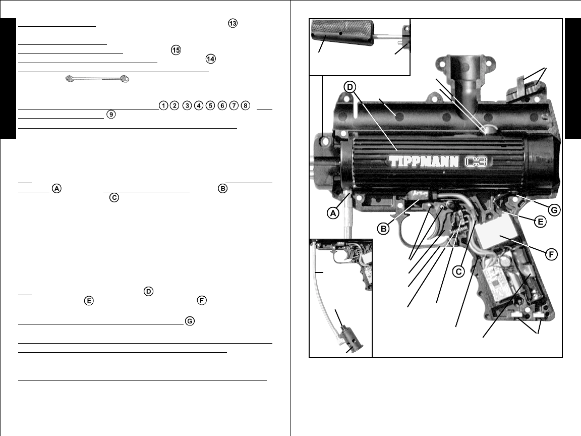
• Remove the Velocity Screw by turning it counterclockwise with
Forearm Grip / Front Valve /
Exhaust Valve (is not visible
until assembly removed)
Rear
Sight
Right
Receiver
Half
Trigger
Trigger
Guard
Trigger
Pins (2)
Trigger
Spring Trigger
Switch
Adapter
Nuts (2)
Barrel Seal
Barrel
Seal
O-ring
Ignition Module Wires
Shown Positioned
for left receiver half
reassembly.
Ribbon for
Battery removal
Gas Line
Regulator
Adjustment
Knob
Regulator
PARTS POSITIONED FOR
LEFT RECEIVER HALF
REASSEMBLY
a large flat screwdriver, then remove the spring and buffer o-ring.
• Push the piston out the back of the rear valve body.
• Clean the Rear Valve internal surfaces with WD-40 & wipe clean.
• Clean the piston with WD-40 and wipe clean. Inspect the two
piston o-rings for wear (replace if necessary) and lubricate
with TippmannTM marker oil.
HOLE IN BOLT
For Linkage Arm
Positioned In Barrel Slot
19
E
N
G
L
I
S
H
Receiver Assembly (continued from page 18)
18
E
N
G
L
I
S
H
LEFT RECEIVER HALF INSTALLATION:
28) Place left receiver half onto right half making sure that the
lip on the receiver engages the lower fin on the chamber.
29) Screw in bottom 4 receiver bolts to hold in place .
30) Carefully work barrel out until you can see the hole in the
Front Bolt for the linkage arm . Slide the linkage arm into the
forearm grip with end angled down and insert into slot inside the
left grip half and then insert other end into hole in Front bolt .
31) Carefully work the barrel completely in to the back of the
receiver. Check to be sure that the barrel is correctly aligned with
the feeder by sliding the forearm grip back and then inserting
your finger into the feed elbow and feeling where barrel hole
and feeder hole fit together. When correctly aligned, this will
be a smooth transition between the receiver and barrel.
32) With barrel/feeder holes correctly aligned, tighten the 4
remaining receiver bolts , and the 2 feed elbow bolts .
33) Insert the Front Sight/Under Barrel Tube assembly through
the front grip and into the receiver until you can insert the Push
Pin to attach it.
34) Reinstall battery: Lay the battery removal ribbon across the
module battery compartment keeping its loose end free (to pull
and lift battery out at next replacement). Next insert the battery
into module on top of ribbon, making sure to keep the
positive(+) end towards top of marker. Reattach left side grip
with 2 grip screws .
35) Attach Regulator Adapter with 2 bolts .
36) Attach Regulator with 2 bolts .
37) Turn marker over and attach the 2 banjo fittings of the gas
hose assembly into the right receiver half.
38) Insert End Cap into the back end of the receiver.
Marker is now reassembled. You will need to adjust the velocity
before using.
27) Make sure all parts are in place before installing the left
receiver half (see page 17).
• With Piston o-rings lubricated, insert piston into the Rear Valve
(closed end of piston goes in first).
• Insert the spring, buffer o-ring and carefully screw the Velocity
Adjustment Screw in until flush with end of the Rear Valve body.
17) Pull the Forearm Grip/Front Valve/Exhaust Valve Assembly
from the Chamber.
• Clean the back face of the Front Valve Body with WD-40 and
wipe clean. Clean and inspect the Big O-ring on back face of
the Front Valve Body – replace if necessary.
• Clean the exhaust piston and u-cups. Inspect u-cups for
wear (replace if necessary) and lubricate them first with a
very light coat of white lithium grease, then with a very light
coat of TippmannTM marker oil on top of the grease. NOTE:
Too much grease or oil can cause your spark plug to short out.
ASSEMBLING THE INSPECTED, CLEANED AND
LUBRICATED INTERNAL PARTS.
18) Slide the forearm grip/front valve body/exhaust valve
assembly into front end of the chamber.
19) Insert Rear Valve into back end of the chamber and be
sure to align hole in valve top with hole in chamber top.
20) Reconnect ground wire to chamber assembly with bolt and
lockwasher.
21) Insert Barrel Seal (flat end first with o-ring in place) into
chamber /rear valve– (make sure to turn barrel seal top so
barrel will fit down into it when barrel is installed.)
22) Insert Chamber Assembly (rear valve end first) – into right
receiver half.
23) Place Spark Plug back into slot in right receiver half.
24) Plug chamber ground wire and Spark Plug wire
onto the ignition module.
25) Lift the left end of the chamber enough to insert the gas
line into the slot below the front valve body, then lower the
chamber making sure that the lip on the receiver engages
the lower fin on the chamber.
26) It is easiest to insert the barrel and barrel seal o-ring into
the right receiver half at this time so that the barrel holds the
barrel seal o-ring properly in place. See illustration on next page.
a) Carefully position o-ring on top of the barrel seal.
b) Make sure front bolt is properly aligned in barrel with the hole
for the linkage arm visible in the slot on the side of the barrel.
c) Insert the barrel and then carefully work the barrel into the
receiver (by turning and sliding it) until the barrel bottom holds
the barrel seal o-ring in place. This may take a few tries and if
you damage the o-ring replace it.
BARREL
O-RING
PROPERLY
IN PLACE
BARREL SEAL
BARREL
INSERTION BARREL
SLOT
Receiver Assembly (continued on page 19)
Chamber Disassembly (continued from page 17)

20
Specifications
Model .............................................................. TippmannTM C3TM
Caliber ................................................................................. .68
Action ...........................................................Slide Action Pump
Power/Propane Supply.............. Disposable Propane Cylinder
Standard Barrel Length ....................................................... 13”
Overall Length (with standard barrel & no tank).............. 17.6”
Weight (without tank)...................................................3.75 lbs.
Effective Range ............................................................ 150+ ft.
Velocity ... Adjustable: always measure your marker’s velocity
before playing paintball and never shoot at velocities in excess
of 300 feet per second (see Velocity Adjustment page 9).
TROUBLESHOOTING
If your marker will not fire:
•Check to be sure the safety is in the FIRE position. See
safety instructions on page 4.
•Check to be sure your propane tank is not empty.
•Battery may be bad. See battery replacement on page 8.
•The Spark Plug may be dirty and need to be cleaned.
See Spark Plug Cleaning and Maintenance on page 13.
•Fuel Air Mixture may need adjustment.
See Regulator Adjustment on page 14.
•Internal wire(s) may be disconnected or damaged. Follow
Marker disassembly instructions beginning on page 14,
to disassemble and inspect internal wires and connections.
If your marker misfires:
• The Spark Plug may be dirty and need to be cleaned.
-See Spark Plug Cleaning and Maintenance on page 13.
If the electronics short out:
• The Spark Plug may be dirty and need to be cleaned.
-See Spark Plug Cleaning and Maintenance on page 13.
•Internal wire(s) may be disconnected or damaged.
-Follow Marker disassembly instructions beginning on page
14, to disassemble and inspect internal wires and connections.
If you smell propane when using your marker:
• Other than briefly when attaching or detaching the propane
cylinder, if you still smell propane, do not fire the marker -
remove the propane cylinder and seek qualified repair from
TippmannTM or your local paintball dealer.
TippmannTM C3TM - Frequently Asked Questions
1. Why should I buy the new C3TM Marker?
Convenience! With over 50,000 shots per 16 ounce tank and
the accessibility of propane cylinders at many retail locations,
paintball players can spend more time playing paintball and less
time trying to fill or find a place to fill their C02 or Nitrogen tank.
2. How does the performance compare to C02 or Nitrogen /
Compressed Air?
Propane has the same velocity range of C02, Nitrogen or
Compressed Air but it is not affected by temperature changes
and it maintains a consistent velocity for every shot.
3. Can I adjust the ball velocity with a C3TM Marker?
Yes. The C3TM Marker has a velocity range similar to any
standard marker. The velocity can be adjusted from
approximately 240 to 310 FPS at the back of the C3TM Marker
using a large flat head screwdriver.
4. Is there really much of a savings using Propane vs. C02
or Nitrogen?
Yes. It costs under $8 for a disposable 16.4-ounce propane
tank, versus $30 to $35 for a 20-ounce CO2 tank. Plus you
have to fill your CO2 tank after every 1,000 shots! To fill your
CO2 tank for 50,000 shots you would have to spend an
additional $250!
5. Is propane safe to use?
Yes, like any fuel source when handled according to the
appropriate safety instructions. Propane is actually a low
pressure gas that uses only a small amount of fuel in an internal
combustion chamber. The propane is never actually released
into the air by the marker and is very safe to use.
6. I noticed that as I was tightening the Propane to the
marker, I detected the smell of Propane. Is this normal?
Yes. As the tank is being threaded into the regulator, a small
amount of gas may escape. The Propane smell will go away
after a few seconds.
7. Where else is propane used?
Propane is used safely in dozens of consumer products like
nail guns, power tools, household appliances, outdoor lighting,
camping equipment and cars. When used in these types of
items or in an internal combustion chamber like the C3TM,
propane is a convenient and effective fuel.
8. What happens if there is a leak in a connection on the
marker?
Simply unhook the propane cylinder from the marker. Contact
Frequently Asked Questions
(continued on page 22)
21

WARRANTY AND REPAIR POLICY
WARRANTY OR REPAIR PROCEDURE
If you should encounter any problems with your marker and
you have aftermarket parts on your marker, please test it with
the original stock parts before sending it in.
Always unload and remove propane supply before shipping a
marker (see page 12). Do not ship your propane supply tank.
For warranty and non-warranty repair:
1. Ship or deliver your product(s) to:
Tippmann Sports, LLC
2955 Adams Center Road
Fort Wayne, IN 46803
2. Postage or delivery charges must be prepaid.
3. Include a brief statement regarding the requested repair,
your name, return address and telephone number where
you can be reached during normal business hours, if possible.
Our policy is to complete the necessary repair work within 24
hours and return it to you via regular ground UPS. If you wish to
have it returned using a faster service, you can request for NEXT
DAY AIR UPS OR SECOND DAY AIR UPS. You will be charged
for this service and must include your credit card number with
the expiration date. Your card will be charged the difference in
additional cost over regular ground shipping service.
Tippmann Sports, LLC warrants that this product is found free
from defects in materials and workmanship for a period of 1
year from the original date of purchase by the initial owner/
purchaser. This warranty does not apply to defects discovered
after purchase which were caused by the unauthorized
modifications and alterations of our product. Tippmann Sports,
LLC will repair or replace, without charge, any of its markers that
have failed through defect in material or workmanship. Tippmann
is dedicated to providing you with the ultimate paintball marker
and the quality support necessary for satisfactory play.
WARRANTY REGISTRATION
Register your marker either:
1. On line at www.tippmann.com.
2. Complete attached registration card and mail to the above
address.
your local dealer or TippmannTM Service and we can fix your
marker. Assuming there is no issue with the propane tank, the
leak is handled the same way as a standard C02 leak.
9. When using the marker I noticed the marker felt warm. Is
this normal?
It is normal for the marker to become very warm when shooting.
10. I see TippmannTM has its own propane fuel; can I use any
standard propane cylinder?
To make it easier for the paintball dealer and consumer, we
have our own TippmannTM branded propane cylinders that we
recommend for use with the C3TM Marker. However, any
standard disposable propane cylinder will fit on the C3TM.
11. Why did TippmannTM launch this as a pump action marker?
This is a very new technology and the pump-action system
worked much better with this type of fuel system. With a pump-
action system, this marker will open the game to new players
who want a quality marker and who do not want to shoot too
much paint at one time or to the serious scenario players who
want to use the C3TM as a stock marker to fine tune their strategies
in scenario style play.
12. What are the plans for a semi automatic?
We are planning many variations and upgrades to the C3TM
Marker but no final time schedule has been developed.
13. What accessories can I add to this marker?
At this time there are no accessories to add to this marker.
Simply add the propane fuel source and a standard ball hopper
and you are ready to go.
14. What happens if I pump the marker more than once, will
I get more power?
No. Extra pumps do not add any extra power but will add a
second ball in the barrel chamber. You want to only pump one
time to avoid getting two or more balls lodged in the barrel.
15. Is there any warranty and who does the repairs?
The C3TM is covered by the standard 1-year TippmannTM
warranty. Many of our Tech Centers will be trained to handle
the repairs of the C3TM or any other TippmannTM marker.
16. Do any fields offer pump-action only areas or
tournaments?
More fields are developing a pump-action or stock area at their
facilities. Many players are now developing groups to play
stock games to work on their scenario strategies or focus on
improving their aim and accuracy.
Frequently Asked Questions (continued from page 21)
22 23
Purchased from Date
Serial Number:
Your Name (print)
Phone #
Country
Address
Country
2955 ADAMS CENTER ROAD
FT. WAYNE, IN 46803 USA
Male
Age Female
TIPPMANNTM
E-mail
#
City State Zip
City State Zip
Warranty Registration online at www.tippmann.com
or complete this warranty card and mail to TippmannTM.
C3TM
THIS PAGE INTENTIONALLY LEFT BLANK
Acheté du Date
Nombre comprador Decha
Numéro Sérial:
Número de Serie:
Votre nom
Nombre (letra de molde)
No. de téléphone
Teléfono
Pays
País
Addresse
Dirección
Pays
País
2955 ADAMS CENTER ROAD
FT. WAYNE, IN 46803 USA
Mâle
Hombre
Âge
Edad Femelle
Mujer
TIPPMANN
TM
E-mail
#
Ville État Code Postale
Ciudad Estado Código Postal
Ville État Code Postale
Ciudad Estado Código Postal
L’Insription de Garantie sur l’internet à www.tippmann.com ou
complétez la carte de d’inscription et l’envoyez à Tippmann
TM
.
Registro de Garantia via On line a www.tippmann.com
o complete esta tarjeta de garantía y envandola por correo regular a Tippmann
TM
.
C3
TM
Inside
Back
Cover
Blank
