Tmc Et4000 Users Manual UG For PDF V8 062502
ET4000 to the manual eadc20be-b0d0-45b0-a7fe-903a92e152c9
2015-02-02
: Tmc Tmc-Et4000-Users-Manual-486208 tmc-et4000-users-manual-486208 tmc pdf
Open the PDF directly: View PDF ![]() .
.
Page Count: 92
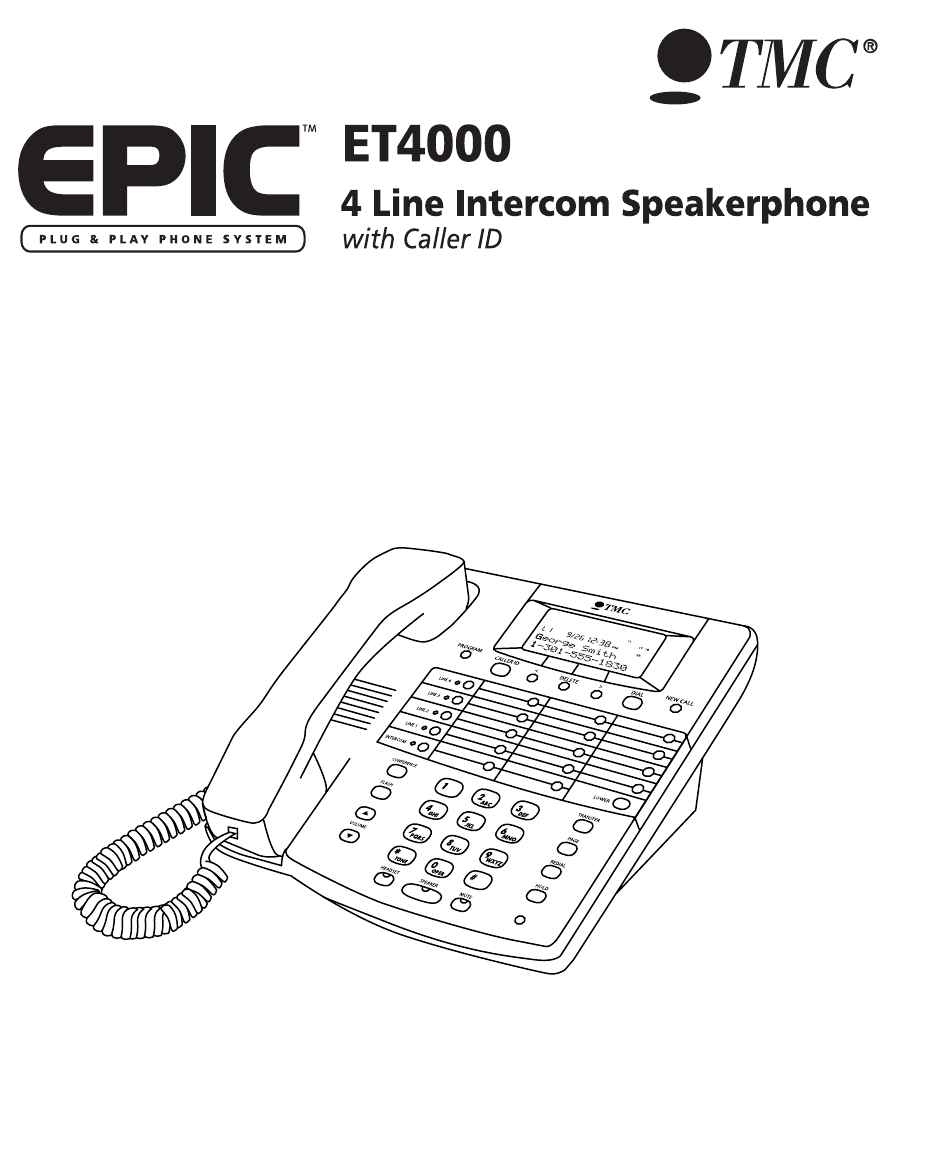
Please read before using telephone.
User’s Guide
ET4000 UG for PDF v8 062502.qxd 6/25/02 12:51 PM Page 1

Getting Started
Congratulations! You’ve purchased a TMC EPIC System Intercom
Speakerphone that meets the highest standards for quality and convenience in
the Small Office/Home Office environment. To get the most from your system,
please take time to read this guide thoroughly.
i
IMPORTANT SAFETY INSTRUCTIONS
When using your telephone equipment, basic safety precautions should always
be followed to reduce the risk of fire, electric shock and injury to persons, includ-
ing the following:
1.
2.
3.
4.
SAVE THESE INSTRUCTIONS
Do not use this product near water, for example, near a bath tub, wash bowl,
kitchen sink, or laundry tub, in a wet basement, or near a swimming pool.
Avoid using a telephone (other than a cordless type) during an electrical
storm. There may be a remote risk of electric shock from lightning.
Do not use the telephone to report a gas leak in the vicinity of the leak.
Use only the power cord and batteries indicated in this manual. Do not dis-
pose of batteries in a fire. They may explode. Check with local codes for pos-
sible special disposal instructions.
ET4000 UG for PDF v8 062502.qxd 6/25/02 12:51 PM Page 2
ii
The TMC EPIC System Intercom Speakerphone is designed for easy installation in your home
or office. However, it is important that you follow these few simple guidelines:
- Take a few minutes to read this manual so that you thoroughly understand the instructions to
be followed for proper installation of your EPIC System phones.
- This User’s Guide provides easy to understand directions for operation of your system. Please
retain these instructions for future reference when adding stations or making changes to your
system.
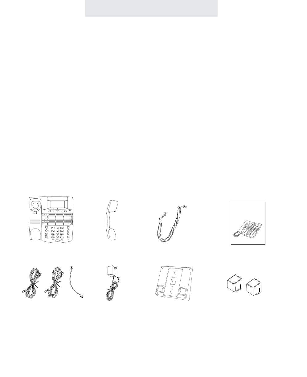
Packing List
Remove the unit from the package and check this list to be certain all parts are included:
To order any packing list items, call toll-free 1-800-TMC-1638.
Telephone Base Unit
Telephone Line Cords
(2 long and 1 short)
Wall Mount
Bracket/Desk Pedestal
Handset Coiled Handset Cord This User’s Guide
User’s Guide
Getting Started
Before you begin . . .
AC Adapter Two Desk Pedestal
Feet
ET4000 UG for PDF v8 062502.qxd 6/25/02 12:51 PM Page 3

Optional Accessories
To order an accessory or get the name of the TMC Dealer nearest you, call toll-free
1-800-TMC-1638.
iii
The External Feature Module is an exciting addition to
the EPIC System. It offers ONE of the following fea-
tures, which you decide by setting switches on the mod-
ule itself. If you ever need more than one feature, you
can add additional Feature Modules to your system.
External Feature Module (Model number 800-EFM)
Each External Feature Module offers ONE of the following features:
Music On Hold Adapter
Enables you to hook-up your radio or a continuous loop recorded message to the system to pro-
vide professional music or a recorded message to callers on hold.
External Paging Adapter
Allows the connection of an external amplifier and speaker to the system, for paging from any
EPIC telephone. Perfect for warehouses, outdoors, or for making announcements throughout an
entire office.
Door Intercom/Door Opener Adapter
Enables you to connect a door intercom speaker to the system. Also enables you to connect a
magnetic door strike, which can be opened from any station. Perfect for warehouses, front doors
or unattended entrances.
Other Optional Accessories:
25-foot handset cord headset25-foot line cord
ET4000 UG for PDF v8 062502.qxd 6/25/02 12:51 PM Page 4

Getting Started . . . . . . . . . . . . . . . . . . . . . . . . . . . . . . . . . . . . . . . . . . . .i
Location of Controls . . . . . . . . . . . . . . . . . . . . . . . . . . . . . . . . . . . . . . .vii
Installing Your System . . . . . . . . . . . . . . . . . . . . . . . . . . . . . . . . . . . . . .1-9
Step 1: Identify Your Existing Wiring System . . . . . . . . . . . . . . . . .1
Step 2: Plan Your Installation . . . . . . . . . . . . . . . . . . . . . . . . . . . . .2
Step 3: Install Desk/Table Top Phones . . . . . . . . . . . . . . . . . . . . . .4
Step 4: Install Wall Mounted Phones . . . . . . . . . . . . . . . . . . . . . . .6
Assigning Station Numbers . . . . . . . . . . . . . . . . . . . . . . . . . . . . . .8
Verifying Proper Installation . . . . . . . . . . . . . . . . . . . . . . . . . . . . . .9
Setting Up Your System . . . . . . . . . . . . . . . . . . . . . . . . . . . . . . . . . . . . .10-19
Setting Up Your System at a Glance . . . . . . . . . . . . . . . . . . . . . . .10
Setting Automatic Line Selection . . . . . . . . . . . . . . . . . . . . . . . . . .12
Setting Distinctive Ringing . . . . . . . . . . . . . . . . . . . . . . . . . . . . . . .13
Setting Up Toll Restriction . . . . . . . . . . . . . . . . . . . . . . . . . . . . . . .14
Setting System Call Privacy On/Off . . . . . . . . . . . . . . . . . . . . . . . .18
Setting Up Private, Auxiliary and Unconnected Lines . . . . . . . . . . .19
Operating Your System . . . . . . . . . . . . . . . . . . . . . . . . . . . . . . . . . . . . .20-43
Using the Desk Pedestal/Wall Mount Bracket . . . . . . . . . . . . . . . . .20
Indicator Light Description . . . . . . . . . . . . . . . . . . . . . . . . . . . . . . .21
Setting Ringers On/Delayed/Off . . . . . . . . . . . . . . . . . . . . . . . . . . .22
Adjusting Volume Levels . . . . . . . . . . . . . . . . . . . . . . . . . . . . . . . .23
Making a Tone/Pulse Selection . . . . . . . . . . . . . . . . . . . . . . . . . . .24
Making and Answering a Call . . . . . . . . . . . . . . . . . . . . . . . . . . . . .25
Using Redial . . . . . . . . . . . . . . . . . . . . . . . . . . . . . . . . . . . . . . . . .26
Using Hold . . . . . . . . . . . . . . . . . . . . . . . . . . . . . . . . . . . . . . . . . .27
Using Another Line During a Conversation . . . . . . . . . . . . . . . . . . .28
iv
Table of Contents
ET4000 UG for PDF v8 062502.qxd 6/25/02 12:51 PM Page 5

v
Table of Contents
Operating Your System (Continued)
Conferencing Calls . . . . . . . . . . . . . . . . . . . . . . . . . . . . . . . . . . . .29
Transferring Calls . . . . . . . . . . . . . . . . . . . . . . . . . . . . . . . . . . . . .30
Using Caller ID . . . . . . . . . . . . . . . . . . . . . . . . . . . . . . . . . . . . . . .32
Using Telephone Company Voice Mail . . . . . . . . . . . . . . . . . . . . . .34
Using Flash . . . . . . . . . . . . . . . . . . . . . . . . . . . . . . . . . . . . . . . . . .35
Using Mute . . . . . . . . . . . . . . . . . . . . . . . . . . . . . . . . . . . . . . . . . .36
Using Do Not Disturb . . . . . . . . . . . . . . . . . . . . . . . . . . . . . . . . . . .37
Using Line Reserve . . . . . . . . . . . . . . . . . . . . . . . . . . . . . . . . . . . .38
Releasing Call Privacy . . . . . . . . . . . . . . . . . . . . . . . . . . . . . . . . . .39
Using Toll Restriction . . . . . . . . . . . . . . . . . . . . . . . . . . . . . . . . . . .40
Using the Call Timer . . . . . . . . . . . . . . . . . . . . . . . . . . . . . . . . . . .41
Using a Headset with Your Epic Telephone . . . . . . . . . . . . . . . . . .42
Adjusting Your Telephone’s Time and Date . . . . . . . . . . . . . . . . . .43
Memory Dialing . . . . . . . . . . . . . . . . . . . . . . . . . . . . . . . . . . . . . . . . . . .44-49
Memory Features . . . . . . . . . . . . . . . . . . . . . . . . . . . . . . . . . . . . .44
Using Memory Dial . . . . . . . . . . . . . . . . . . . . . . . . . . . . . . . . . . . .45
Using Personal Directory Dial . . . . . . . . . . . . . . . . . . . . . . . . . . . .46
Using Shared Directory Dial . . . . . . . . . . . . . . . . . . . . . . . . . . . . . .47
Special Memory Features . . . . . . . . . . . . . . . . . . . . . . . . . . . . . . .48
Intercom Operation . . . . . . . . . . . . . . . . . . . . . . . . . . . . . . . . . . . . . . . .50-57
Making Intercom Calls . . . . . . . . . . . . . . . . . . . . . . . . . . . . . . . . . .50
Answering Intercom Calls . . . . . . . . . . . . . . . . . . . . . . . . . . . . . . .51
Making Pages . . . . . . . . . . . . . . . . . . . . . . . . . . . . . . . . . . . . . . . .52
Answering Pages . . . . . . . . . . . . . . . . . . . . . . . . . . . . . . . . . . . . . .53
Selecting Intercom Ring, Intercom Voice, or Handsfree . . . . . . . . .54
Using Off Hook Voice Announce . . . . . . . . . . . . . . . . . . . . . . . . . .55
Monitoring a Room Using the Intercom . . . . . . . . . . . . . . . . . . . . .56
Naming Stations . . . . . . . . . . . . . . . . . . . . . . . . . . . . . . . . . . . . . .57
ET4000 UG for PDF v8 062502.qxd 6/25/02 12:51 PM Page 6

Table of Contents
Expanding the Epic System . . . . . . . . . . . . . . . . . . . . . . . . . . . . . . . . .58-59
Standard Configuration . . . . . . . . . . . . . . . . . . . . . . . . . . . . . . . . .58
Private Lines . . . . . . . . . . . . . . . . . . . . . . . . . . . . . . . . . . . . . . . .58
Auxiliary Lines . . . . . . . . . . . . . . . . . . . . . . . . . . . . . . . . . . . . . . .59
Centrex Operation . . . . . . . . . . . . . . . . . . . . . . . . . . . . . . . . . . . . . . . . .60-63
Using Centrex with your EPIC Telephone . . . . . . . . . . . . . . . . . . . .60
Storing the Centrex Prefix . . . . . . . . . . . . . . . . . . . . . . . . . . . . . . .61
Setting up a Telephone as a Centrex Console . . . . . . . . . . . . . . . .62
Setting a Telephone to Ring a Centrex Console . . . . . . . . . . . . . . .63
Additional Information . . . . . . . . . . . . . . . . . . . . . . . . . . . . . . . . . . . . . .64-78
Using Other Telephones with your EPIC Telephone . . . . . . . . . . . .64
Using the Data/Fax Jack . . . . . . . . . . . . . . . . . . . . . . . . . . . . . . . .65
Using Optional External Feature Module . . . . . . . . . . . . . . . . . . . .66
Replacing Your Battery . . . . . . . . . . . . . . . . . . . . . . . . . . . . . . . . .68
Adjusting Held Call Reminder . . . . . . . . . . . . . . . . . . . . . . . . . . . .69
Adjusting Auto Hold Drop Time . . . . . . . . . . . . . . . . . . . . . . . . . . .70
Adjusting Flash Length . . . . . . . . . . . . . . . . . . . . . . . . . . . . . . . . .71
Erasing All Feature Settings . . . . . . . . . . . . . . . . . . . . . . . . . . . . . .72
Setting the Loop Voltage Detector . . . . . . . . . . . . . . . . . . . . . . . . .73
Troubleshooting Guide . . . . . . . . . . . . . . . . . . . . . . . . . . . . . . . . . .74
FCC Information . . . . . . . . . . . . . . . . . . . . . . . . . . . . . . . . . . . . . .76
Warranty Information . . . . . . . . . . . . . . . . . . . . . . . . . . . . . . . . . . .78
Index . . . . . . . . . . . . . . . . . . . . . . . . . . . . . . . . . . . . . . . . . . . . . . . . . . . .80-81
vi
ET4000 UG for PDF v8 062502.qxd 6/25/02 12:51 PM Page 7
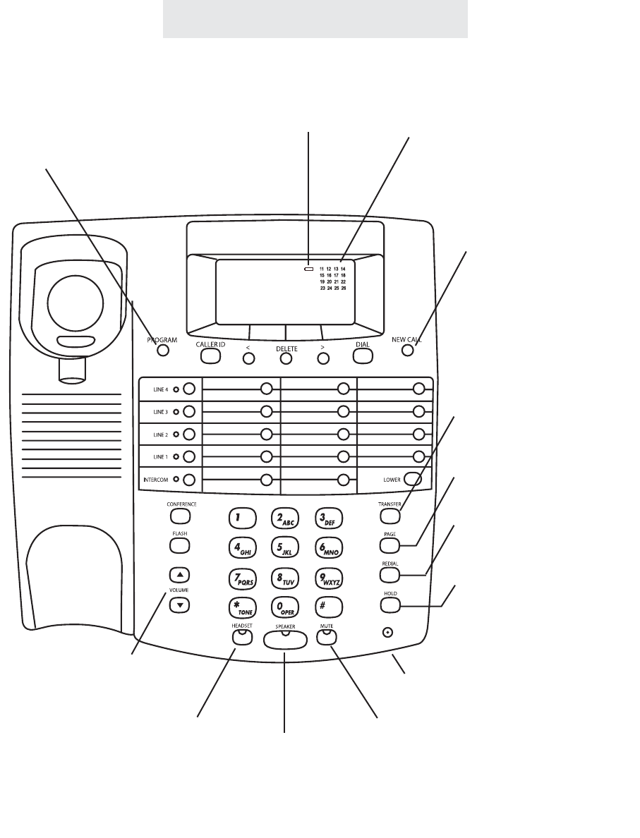
Location of Controls
vii
SPEAKER Button and
Indicator (pp. 25, 50-56)
Microphone (pp. 25, 50-56)
LOW BATTERY
Indicator (p. 68)
VOLUME Control
Buttons (p. 23)
Station In-Use Indicators (p. 21)
MUTE Button and
Indicator (p. 36)
HEADSET Button and
Indicator (p. 42)
HOLD Button (p. 27)
REDIAL Button (p. 26)
PAGE Button (pp. 52-53)
TRANSFER Button
(pp. 30-31)
NEW CALL Lamp (pp. 32, 34)
PROGRAM Button (pp. 10-19, 44-57)
ET4000 UG for PDF v8 062502.qxd 6/25/02 12:51 PM Page 8
viii
Location of Controls
LEFT ARROW Button (pp. 32-33, 46-47)
DELETE Button (pp. 25, 32-33)
RIGHT ARROW Button (pp. 32-33, 46-47)
DIAL Button (pp. 32-33, 46-47)
CALLER ID Button (pp. 32-33)
LOWER Button (p. 45)
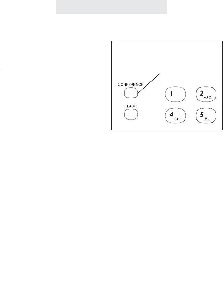
CONFERENCE Button (p. 29)
FLASH Button
(pp. 35, 48)
Battery Compartment (p. 68)
Line Jacks (pp. 4, 6)
AC Adapter Jack (pp. 5-6)
MEMORY Buttons (p. 45)
LINE Buttons and
Indicators (pp. 21, 25, 38)
INTERCOM Button and
Indicator (pp. 21, 50-53)
ET4000 UG for PDF v8 062502.qxd 6/25/02 12:51 PM Page 9
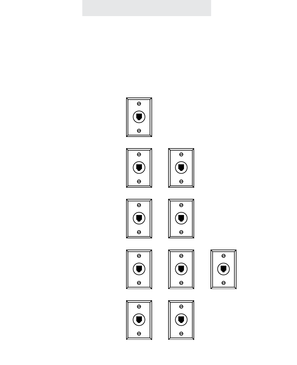
Step 1: Identify Your Existing Wiring System
In order for you to properly connect your EPIC System to an existing wiring sys-
tem, it is important that you understand its configuration. The following are the
most common multiple line situations. They consist of either one or both types of
standard telephone jacks: The RJ11 Single Line Jack and the RJ14 Double Line
Jack. Your system should match one of them.
Line 1-2
ix
Installing Your System
2 incoming lines with
2 wall jacks
3 incoming lines with
2 wall jacks
3 incoming lines with
3 wall jacks
4 incoming lines with
2 wall jacks
2 incoming lines with
1 wall jack
Line 1 Line 2
Line 3
Line 2 Line 3
Line 3-4
Line 1-2
Line 1
Line 1-2
ET4000 UG for PDF v8 062502.qxd 6/25/02 12:51 PM Page 10
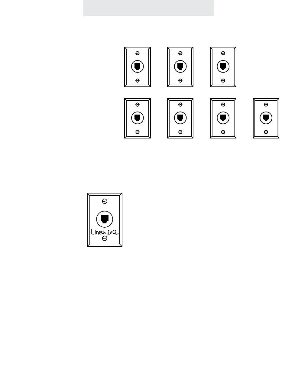
Step 1: Identify Your Existing Wiring System (Continued)
Label the jacks at each location.
Identify and label the jacks at each location to avoid the possibility of improperly connecting any
of the lines to the telephones. To do so, write the line number(s) directly on each jack plate with
a felt-tip pen.
If you have difficulty in identifying wall jacks.
Call the vendor who installed the inside wiring and ask for assistance in identifying your existing
wiring system and jacks.
If you are installing new wiring and jacks.
If any new telephone wiring and modular jacks need to be installed, and four lines are to be used,
install two-line RJ14 jacks at each telephone location. Each RJ14 jack accommodates two tele-
phone lines.
Installing Your System
4 incoming lines with
3 wall jacks
4 incoming lines with
4 wall jacks
Line 1-2
Line 1 Line 2 Line 3 Line 4
Line 3 Line 4
For example:
1
ET4000 UG for PDF v8 062502.qxd 6/25/02 12:51 PM Page 11

Installing Your System
Step 2: Plan Your Installation
Up to 16 Epic System telephones may be connected to form your office/home
configuration. Each phone must be assigned a different station number, from 11
to 26.
IMPORTANT: Each Epic System telephone must be connected to the same Line
1 telephone number for proper operation. The remaining lines may or not be con-
nected to each station as you desire.
Standard Installation:
Your Epic telephones come factory-set for a standard “Shared” installation, which
is also called “square” in telephone terminology. This means that Line 1 is to be
connected to the same Line 1 telephone number at all the stations, Line 2 is to be
connected to the same Line 2 telephone number at all the stations, and so on for
Lines 3 and 4.
This is the desired setup for most installations, and if this is how you will be con-
necting your Epic System, you do not need to change any of the line connection
settings in the telephones. You need only connect the phones to the telephone
lines, and then follow the instructions on page 9 to be sure that you have con-
nected the telephone numbers in the same order to each station.
Installations with Private Lines, Auxiliary Lines, and Unconnected Lines:
You may wish to connect private lines to Lines 2, 3 or 4 at some or all of your tele-
phones. A private line is a telephone number that is connected to only one of the
Epic telephones, and is not shared with any other station. You may also wish to
connect auxiliary lines to Lines 2, 3 or 4 at some of your telephones. An auxiliary
line is a telephone number that is shared by two or more stations, but which is a
different telephone number than the corresponding line at the other stations.
These sort of installation requirements are common in Centrex environments, or
in companies where clusters of telephones share common lines. In addition you
may wish to leave some lines unconnected at some stations.
If your installation has any of these requirements, carefully fill out the worksheet
on the following page and use it as a guide as you connect the telephone lines
to your Epic telephones, then follow the instructions on page 19 to properly set
each line at each station.
ET4000 UG for PDF v8 062502.qxd 6/25/02 12:51 PM Page 12

Shared Private
L2Aux1
Unconnected
Shared Private
L2Aux1
Unconnected
Shared Private
L2Aux1
Unconnected
Shared Private
L2Aux1
Unconnected
Shared Private
L2Aux1
Unconnected
Shared Private
L2Aux1
Unconnected
Shared Private
L2Aux1
Unconnected
Shared Private
L2Aux1
Unconnected
Shared Private
L2Aux1
Unconnected
Shared Private
L2Aux1
Unconnected
Shared Private
L2Aux1
Unconnected
Shared Private
L2Aux1
Unconnected
Shared Private
L2Aux1
Unconnected
Shared Private
L2Aux1
Unconnected
Shared Private
L2Aux1
Unconnected
Shared Private
L2Aux1
Unconnected
Shared Private
L3Aux1
Unconnected
Shared Private
L3Aux1
Unconnected
Shared Private
L3Aux1
Unconnected
Shared Private
L3Aux1
Unconnected
Shared Private
L3Aux1
Unconnected
Shared Private
L3Aux1
Unconnected
Shared Private
L3Aux1
Unconnected
Shared Private
L3Aux1
Unconnected
Shared Private
L3Aux1
Unconnected
Shared Private
L3Aux1
Unconnected
Shared Private
L3Aux1
Unconnected
Shared Private
L3Aux1
Unconnected
Shared Private
L3Aux1
Unconnected
Shared Private
L3Aux1
Unconnected
Shared Private
L3Aux1
Unconnected
Shared Private
L3Aux1
Unconnected
Shared Private
L4Aux1 L4Aux2
Unconnected
Shared Private
L4Aux1 L4Aux2
Unconnected
Shared Private
L4Aux1 L4Aux2
Unconnected
Shared Private
L4Aux1 L4Aux2
Unconnected
Shared Private
L4Aux1 L4Aux2
Unconnected
Shared Private
L4Aux1 L4Aux2
Unconnected
Shared Private
L4Aux1 L4Aux2
Unconnected
Shared Private
L4Aux1 L4Aux2
Unconnected
Shared Private
L4Aux1 L4Aux2
Unconnected
Shared Private
L4Aux1 L4Aux2
Unconnected
Shared Private
L4Aux1 L4Aux2
Unconnected
Shared Private
L4Aux1 L4Aux2
Unconnected
Shared Private
L4Aux1 L4Aux2
Unconnected
Shared Private
L4Aux1 L4Aux2
Unconnected
Shared Private
L4Aux1 L4Aux2
Unconnected
Shared Private
L4Aux1 L4Aux2
Unconnected
Stn. 11
Stn. 12
Stn. 13
Stn. 14
Stn. 15
Stn. 16
Stn. 17
Stn. 18
Stn. 19
Stn. 20
Stn. 21
Stn. 22
Stn. 23
Stn. 24
Stn. 25
Stn. 26
Station
Number
User’s Name
or Telephone
Location
Mark each line at each station as either Shared, Private, Aux, or
Unconnected. Refer to page 19 if you are not sure of the meaning of
these terms. Note that Line 1 must be “Shared” at all the stations,
meaning that Line 1 must be connected to the same telephone num-
ber at all the stations.
IMPORTANT: If you have circled anything other than “Shared” on this
worksheet, then after installing your phones according to this work-
sheet you must follow the instructions on page 19 to set each phone
as you have marked on this worksheet.
Line 2
Tel #___________
Line 1
Tel #____
Line 3
Tel #___________
Line 4
Tel #___________
Installation
Worksheet
Shared
Shared
Shared
Shared
Shared
Shared
Shared
Shared
Shared
Shared
Shared
Shared
Shared
Shared
Shared
Shared
ET4000 UG for PDF v8 062502.qxd 6/25/02 12:51 PM Page 13
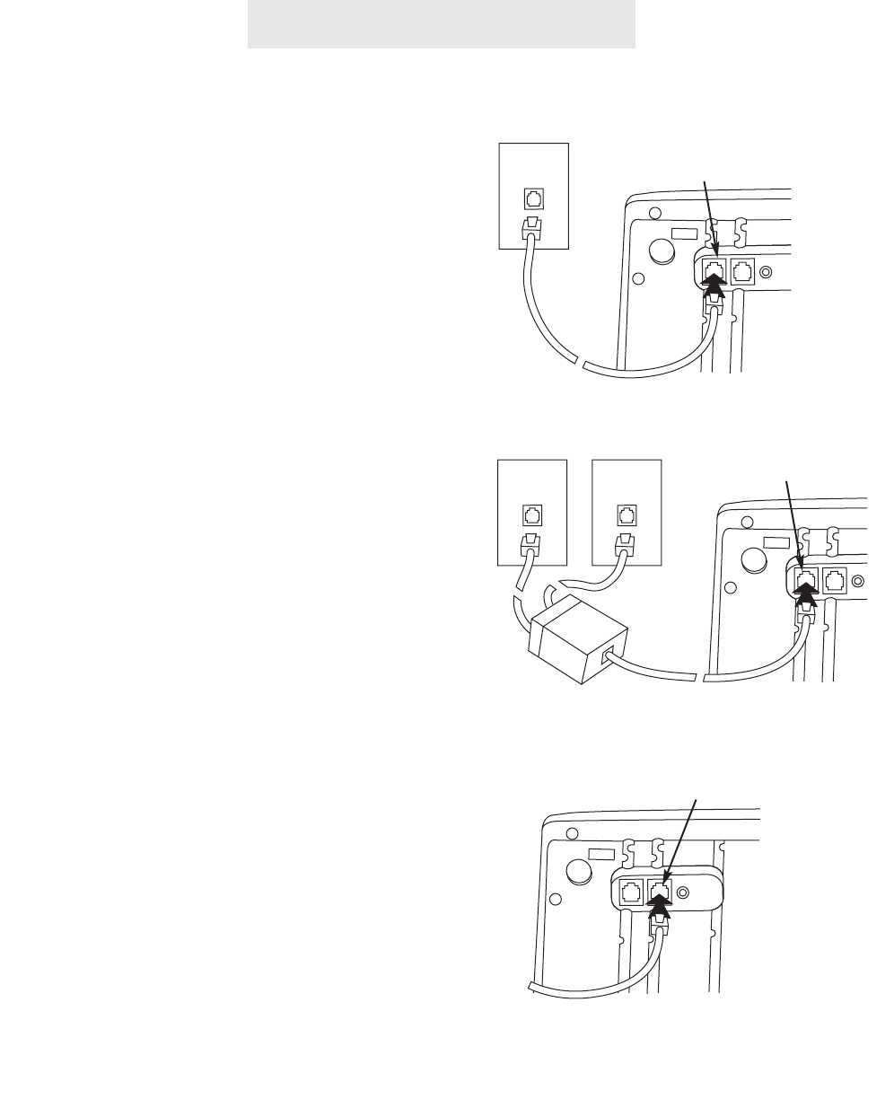
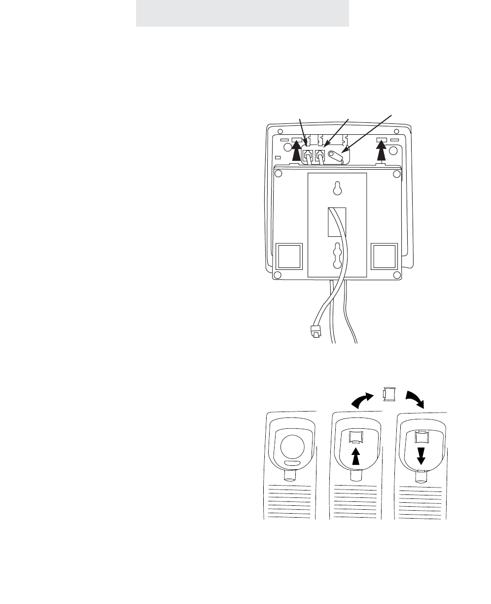
Step 3: Install Desk/Table Top Phones
Installing Your System
1 Connect First Line Cord
Connect one end of a long telephone line cord
to the jack on the bottom of the telephone
labeled L1/L2. Connect the other end to the
jack(s) labeled Lines 1 & 2 either:
directly to the wall jack if it is a two-line RJ14
jack
OR
to a two-line coupler (not provided) if you have
two single-line RJ11 jacks for lines 1 and 2.
Then connect the two cords of the coupler to
the corresponding wall jacks. Two-line cou-
plers are available many places, for example
Radio Shack (part #279-401).
2 Connect Second Line Cord
Connect one end of a long telephone line cord
to the jack on the back of the telephone labeled
L3/L4. Connect the other end to the wall
jack(s) labeled Lines 3 & 4 in the same manner
as described in the previous step.
Note: If you are installing a 3-line EPIC tele-
phone, or are connecting a 4-line telephone to
only 3 lines, connect the other end of the line
cord directly to the wall jack labeled Line 3.
1&2
Line 1
L1/L2
L1/L2
L3/L4
Line 2
Lines
4
ET4000 UG for PDF v8 062502.qxd 6/25/02 12:51 PM Page 14
Step 3: Install Desk/Table Top Phones (Continued)
5
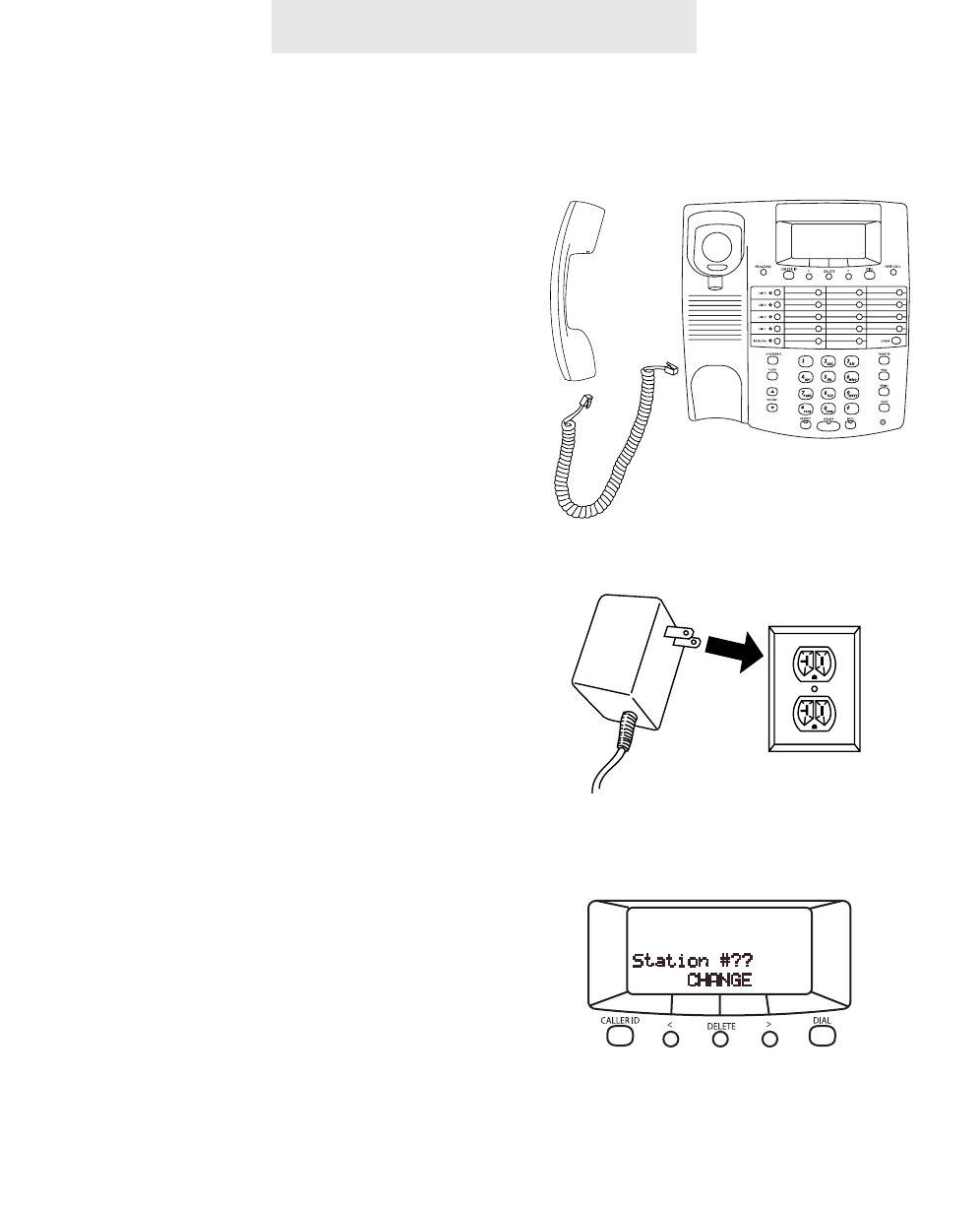
3 Connect Handset
Plug either end of the coiled handset cord into
the handset and the other end into the jack on
the side of the telephone. Place the handset in
the cradle.
4 Connect Power Cord
Plug the AC power cord into the adapter jack
on the bottom of the telephone. Thread the
power cord into the recessed groove. Plug the
AC adapter into an electrical outlet not con-
trolled by a wall switch.
5 Assign a Station Number
Refer to page 8 for detailed instructions on
assigning a station number.
6 Install a 9-Volt Battery (Optional)
It is not necessary for you to install a battery in
your Epic telephone for it to function normally.
In fact, a battery is not even needed to pre-
serve your memory dial numbers in the event
of a power failure. This is because all memory
dial numbers are stored in a static memory
which retains its contents even with no electri-
cal power. The only purpose of having a bat-
tery installed is so that the telephone itself can
function for up to two hours in the event of a
power failure. You may wish to install a battery
in at least one Epic phone for emergency oper-
ation, or have another standard phone avail-
able. If you wish to install a battery, refer to
page 68 for detailed instructions.
7 Verify Proper Installation
IMPORTANT: Please remember to perform the
procedure on page 9, after you assign each
station number, to verify that each telephone is
properly installed.
Installing Your System
ET4000 UG for PDF v8 062502.qxd 6/25/02 12:51 PM Page 15
Step 4: Install Wall Mounted Phones
6
1 Connect Cords to Telephone
If the wall jack is labeled Lines 1 & 2, connect
the short telephone line cord to the jack on the
telephone labeled L1/L2. If the wall jack is
labeled Lines 3 & 4, connect the short cord to
the jack on the telephone labeled L3/L4.
Connect the long telephone line cord to the
other line jack on the telephone and thread it
through its long groove on the bottom of the
phone, then plug the AC power cord into the
adapter jack on the bottom of the telephone,
threading the power cord through its long
groove on the bottom of the phone.
Thread the short telephone cord through the
square hole in the center of the wall mount
bracket, and then attach the wall mount brack-
et to the base of the telephone.
2 Connect Cords to Wall
Connect the long telephone line cord to the
jack by the baseboard, and plug the AC
adapter into the nearest electrical outlet not
controlled by a wall switch.
3 Reverse Handset Hook
Slide the telephone hook out of the cradle,
rotate it 180 degrees so that its tab faces
upward, and then slide it back into the cradle.
4 Connect Handset
Plug either end of the coiled handset cord into
the handset and the other end into the jack on
the side of the telephone. Place the handset in
the cradle.
Installing Your System
L1/L2 L3/L4 AC power cord
ET4000 UG for PDF v8 062502.qxd 6/25/02 12:51 PM Page 16
Step 4: Install Wall Mounted Phones (Continued)
7
5 Assign a Station Number
Refer to page 8 for detailed instructions on
assigning a station number.
6 Install a 9-Volt Battery (Optional)
It is not necessary for you to install a battery in
your Epic telephone for it to function normally.
In fact, a battery is not even needed to pre-
serve your memory dial numbers in the event
of a power failure. This is because all memory
dial numbers are stored in a static memory
which retains its contents even with no electri-
cal power. The only purpose of having a bat-
tery installed is so that the telephone itself can
function for up to two hours in the event of a
power failure. You may wish to install a battery
in at least one Epic phone for emergency oper-
ation, or have another standard phone avail-
able. If you wish to install a battery, refer to
page 68 for detailed instructions.
7 Attach Telephone to Wall
Hold the telephone close to the wall and con-
nect the short telephone line cord to the jack.
Then mount the telephone to the wall plate,
sliding it down firmly so that it locks securely in
place.
8 Verify Proper Installation
IMPORTANT: Please remember to perform the
procedure on page 9, after you assign each
station number, to verify that each telephone is
properly installed.
Installing Your System
ET4000 UG for PDF v8 062502.qxd 6/25/02 12:51 PM Page 17
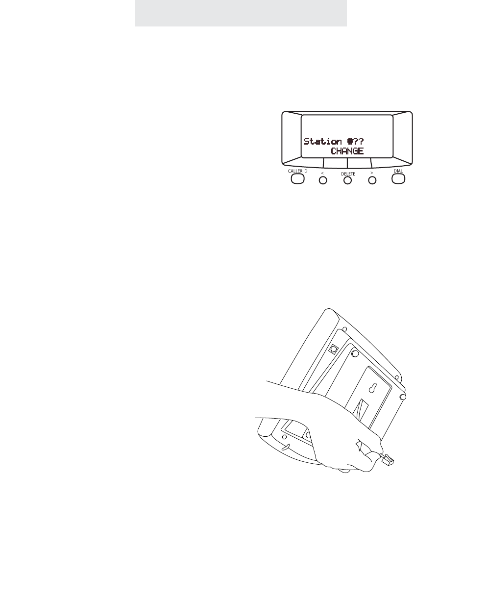
8
Until a telephone is assigned a station number,
the telephone will not operate, and the display
will read “Station #??”. To assign this telephone
a station number, simply press the soft key under
CHANGE repeatedly until the desired station
number is displayed.
It is important to connect the telephone to the
telephone lines before pressing CHANGE, so
that the phone can check other existing sta-
tions in the system, and avoid offering you a
duplicate station assignment.
Note: One phone in the system must be set as
Station #11 in order for all the system features,
such as shared directory dial, to function.
Using Station Names
If you wish, you may also assign your station a
name (See page 57). Then, people will see your
station’s name when you call them on the inter-
com.
Assigning Station Numbers
Each station must be assigned a different station number.
Installing Your System
To assign a station a number:
1 Press PROGRAM.
- The display will read “Program...”
2 Press the soft key under NEXT.
- The display will show the currently
assigned station number.
3Press the soft key under CHANGE
repeatedly, until the desired station
number is displayed.
The choices are Station #11 through
Station #26.
4 Press PROGRAM to exit.
You may follow the above steps at any
time if you wish to change a telephone’s
station number.
Note: If you are connecting your tele-
phone for the first time, the telephone
automatically starts at the station
assignment screen, so you begin with
step #3.
ET4000 UG for PDF v8 062502.qxd 6/25/02 12:51 PM Page 18

Verifying Proper Installation
The following procedure should be used at each telephone to verify proper instal-
lation. Also use this procedure any time you are experiencing difficulty, to test
system configuration and identify possible system connection errors. The phone
must be connected to the AC power supply, line 1 must be connected to the line
1 jack, and the phone must have been assigned an intercom station number.
IMPORTANT: If you ever have a problem with the installation or use of your EPIC
System, please check the following procedure before calling our toll-free cus-
tomer support number for assistance - 1-800-TMC-1638.
First, verify that line 1 is connected to the same telephone number at all the tele-
phones. Do do this, press the line 1 button at one of the telephones. The line 1
LED should be green, the speakerphone LED should be red, and dial tone should
be heard from the speaker. Now go to each of the other stations and make sure
that each line 1 LED is red.
Next, make sure that lines 2, 3 and 4 are connected the same at all the phones
by following the following steps at each telephone:
1. Press the line 1 button. The line 1 LED should be green, the speakerphone
LED should be red, and dial tone should be heard from the speaker.
2. Dial the telephone number for line 2. The line 2 LED should flash slowly. If
the line 2 LED does not flash, then line 2 is improperly connected to this tele-
phone.
3. If this telephone utilizes line 3 and/or line 4, repeat steps 1 and 2, substituting
the respective phone number(s) in step 2.
9
Installing Your System
ET4000 UG for PDF v8 062502.qxd 6/25/02 12:51 PM Page 19

Setting Up Your System
Setting Up Your System At A Glance
The following must be done at each station:
Program
Station Number
Assignment
Automatic Line Selection
Set Distinctive Ringing
Toll Restriction
Set up and Private,
Auxiliary, and
Unconnected Lines
Set Ringers
On/Delayed/Off
Select Intercom Ring,
Voice or Handsfree
Factory Setting
Not assigned
Line 1
None Set
No Restrictions
None Set
All Ringers On
Handsfree
Page
8
12
13
14-17
19
22
54
10
Note: You must program a feature only if you wish to change its setting from the
Factory Setting.
ET4000 UG for PDF v8 062502.qxd 6/25/02 12:51 PM Page 20

11
Setting Up Your System
Setting Up Your System At A Glance (Continued)
The following must be done at Station #11:
Program
Set Toll Restriction
Access Code
Set System Call Privacy
On/Off
Tone or Pulse Dialing
Store Shared Directory
Dial Numbers
Name Stations
Factory Setting
“1234”
On
Tone
None Stored
None Named
Page
14
18
24
47
57
Note: You must program a feature only if you wish to change its setting from the
Factory Setting.
ET4000 UG for PDF v8 062502.qxd 6/25/02 12:51 PM Page 21
12
Setting Up Your System
Setting Automatic Line Selection
To choose which line will be
automatically selected:
1 Press PROGRAM.
- The display will read “Program...”
2 Press the soft key under NEXT
repeatedly, until ”Auto Seize”
appears in the display.
The display will show the current
auto seize setting.
3 Press the soft key under CHANGE
repeatedly, until the desired auto
seize setting is displayed.
The choices are:
Auto Seize:L1 (factory setting)
Auto Seize:L2
Auto Seize:L3
Auto Seize:L4
Auto Seize:INTCM
4 Press PROGRAM to exit.
This feature allows you to choose which line will
be selected automatically when you lift the hand-
set or press the SPEAKER button.
You may choose any of the outside lines or the
Intercom line. If your chosen line is in-use, the
telephone will automatically select the next avail-
able line.
Note: An incoming call that is ringing at your
telephone will be selected automatically when
you lift the handset or press the SPEAKER or
HEADSET button, regardless of the choices you
have made for automatic line selection.
If you wish to select a different line while your
phone is ringing, you must press the desired
LINE button before lifting the handset.
You may choose
any of the outside
lines or the Intercom
line to be selected
automatically when
you lift the handset
or press the SPEAK-
ER button
ET4000 UG for PDF v8 062502.qxd 6/25/02 12:51 PM Page 22

Setting Distinctive Ringing
Setting Up Your System
To assign distinctive rings to
one or more lines:
1 Press PROGRAM.
- The display will read “Program...”
2Press the soft key under NEXT
repeatedly, until ”Distinctive Ring”
appears in the display, and then
press ENTER
The display will show the distinctive
ring setting for Line 1.
3Press the soft key under CHANGE
repeatedly, until the desired distinc-
tive ring setting for Line 1is dis-
played.
The choices are:
L1:RING SOUND #1 (factory set-
ting) through RING SOUND #8
4Press the soft key under NEXT to
see the current setting for Line 2,
and repeat steps 3 and 4 to change
the settings for Lines 2-4.
5Press PROGRAM to exit.
Note: At any time when you have a
particular distinctive ring setting dis-
played, you may press the soft key
under HEAR to hear an example of
that distinctive ring.
All lines are initially set to ring with Ring Sound
#1. If you prefer, you may assign each outside
line one of seven other distinctive ringer tones.
This feature is usually used in one of four ways:
1You may want to assign one of your lines its
own ring tone and leave the other lines set at the
default ring. For example, if line 3 were a private
line at your telephone, you may assign it a dis-
tinctive ring so you could easily recognize calls
ringing on your private line.
2Or, you may want to assign a particular line
the same distinctive ring at all of the stations.
For example, if line 3 were the customer service
line, you may assign line 3 the same distinctive
tone at all the telephones so everybody could
easily tell when this line was ringing.
3Another use of this feature would be to give all
of the lines at your telephone the same distinc-
tive ring so that you could easily tell when your
particular phone was ringing and differentiate it
from the ringing of other nearby telephones.
4Or, you might give all of your lines the same
distinctive ring simply because you prefer that
particular ringing tone.
13
ET4000 UG for PDF v8 062502.qxd 6/25/02 12:51 PM Page 23

Setting Up Your System
To set the system’s toll restric-
tion access code:
At Station #11:
1 Press PROGRAM.
- The display will read “Program...”
2 Press the soft key under NEXT
repeatedly, until “Toll Restriction”
appears in the display, and then
press ENTER.
- The display will read “Access
Code:****.”
3Press the soft key under CHANGE if
you wish to store a new access
code.
4 Enter a 4 digit number.
5 Press PROGRAM to exit.
The Toll Restriction feature enables you to con-
trol outgoing calls and helps you prevent unau-
thorized long distance calls.
The toll restriction access code is set at station
#11. This code is needed when you wish to
change any toll restriction settings or when you
wish to turn toll restriction on or off at a particu-
lar phone. (See page 40).
If you ever forget the access code, simply set a
new code at Station #11. Until you set the
access code, the code will be the one set at the
factory, which is “1234”.
Setting the restricted numbers and
the allowed exceptions at a particu-
lar telephone:
Follow the instructions on the following three
pages for setting toll restrictions at particular
phones. After you set a phone’s toll restrictions,
the settings will not be erased, even in the event
of a power failure. So you do not need to worry
about ever having to re-enter the toll restriction
settings at any of the stations. If you ever do
wish to erase all the toll restriction settings
stored at a particular phone, follow the instruc-
tions on page 49.
Turning toll restriction on/off at a
particular telephone:
Follow the instructions on page 40 for turning
toll restriction on and off at a particular phone.
Note: After setting a station’s restrictions, its toll
restriction is automatically ON. In the future, you
may temporarily override its toll restriction or turn
its toll restriction off for a longer period without
affecting the settings stored in the telephone.
Setting Up Toll Restriction
14
ET4000 UG for PDF v8 062502.qxd 6/25/02 12:51 PM Page 24

Setting Up Your System
To set the restricted numbers
at a particular telephone:
1 Press PROGRAM.
- The display will read “Program...”
2 Press the soft key under NEXT
repeatedly, until “Toll Restriction”
appears in the display, and then
press ENTER.
- The display will read “Enter Code:”
3 Enter the 4 digit toll restriction
access code which was set at
Station #11 (See preceding page).
- You will hear a confirmation beep
and the display will read “Set
Restricted #”
4 Press ENTER
- The display will show the currently
stored Restriction #1, or indicate
“1:” if there is no
Restriction #1 yet stored.
5Press the soft key under CHANGE if
you wish to store a new Restriction
#1, then dial desired restricted num-
ber, up to 6 digits.
6Press the soft key under SAVE.
7 Press the soft key under NEXT and
repeat steps 5-6 if you wish to store
any additional restrictions at this
phone.
15
Setting Up Toll Restriction (Continued)
Toll restriction numbers are set individually at
each station, so the restrictions can vary from
phone to phone.
Some examples of popular restrictions:
“1” ... to restrict all numbers starting with “1”.
“01” ... to restrict all international calls.
“0” ... to restrict all operator-assisted calls.
“#976” ... to restrict all “0976” and “1976” calls.
(When you enter restricted numbers, “#” is a
wildcard that stands for the number “0” or “1”.)
Note: Restrictions are usually just a few digits,
since they prevent the dialing of all numbers
starting with those digits.
Use the Worksheet below to plan your choice of
restricted numbers. If you plan to set any sta-
tions with a different set of restrictions, then use
additional copies of this worksheet.
You can set as
many as five
restricted numbers
at each telephone.
Enter the restricted numbers
exactly as you would dial them
out. Each restriction can be up
to 6 digits long.
1st Restriction
2nd Restriction
3rd Restriction
4th Restriction
5th Restriction
Worksheet
ET4000 UG for PDF v8 062502.qxd 6/25/02 12:51 PM Page 25

16
Setting Up Toll Restriction (Continued)
Setting Up Your System
To completely restrict specific
lines at a telephone:
1 Press PROGRAM.
- The display will read “Program...”
2 Press the soft key under NEXT
repeatedly, until “Toll Restriction”
appears in the display, and then
press ENTER.
- The display will read “Enter Code:”
3 Enter the 4 digit toll restriction access
code which was set at Station #11
(See page 14).
- You will hear a confirmation beep
and the display will read “Set
Restricted #”
4 Press the soft key under NEXT
repeatedly, until “Line Restriction”
appears in the display, and then
press ENTER.
5Press the soft key under CHANGE
repeatedly, until the desired Line 1
Restriction setting is displayed.
The choices are:
L1: NORMAL (factory setting)
L1: RESTRICTED
6Press the soft key under NEXT to
see the current setting for Line 2,
and repeat steps 5 and 6 to change
the settings for Lines 2-4.
7 Press PROGRAM to exit.
In addition to setting specific restrictions at a par-
ticular phone (See preceding page), you may
completely restrict any or all of the lines at a par-
ticular station.
People will not be able to make any outgoing
calls on any lines that are completely restricted
at a station, with the exception of the allowed
numbers at that station and calls to “911”.
However, they will still be able to receive incom-
ing calls on these lines, take calls off hold, and
have full use of the intercom.
The ability to completely restrict lines is useful in
an office where you only want people to make
calls on certain lines at particular stations. You
may also wish to put one station in a public area,
such as a lobby, and completely restrict all or
most of its lines.
ET4000 UG for PDF v8 062502.qxd 6/25/02 12:51 PM Page 26

Setting Up Your System
To set the allowed numbers
at a particular telephone:
1 Press PROGRAM.
- The display will read “Program...”
2 Press the soft key under NEXT
repeatedly, until “Toll Restriction”
appears in the display, and then press
ENTER.
- The display will read “Enter Code:”
3 Enter the 4 digit toll restriction access
code which was set at Station #11
(See page 14).
- You will hear a confirmation beep
and the display will read “Set
Restricted #”
4 Press the soft key under NEXT.
- The display will read “Set Allowed #”
5 Press ENTER
- The display will show the currently
stored Allowed #1, or indicate
“1:” if there is no
Allowed #1 yet stored.
6Press the soft key under CHANGE if
you wish to store a new Allowed #1,
then dial desired allowed number, up
to 10 digits.
7Press the soft key under SAVE.
8 Press the soft key under NEXT and
repeat steps 6-7 if you wish to store
any additional allowed numbers at this
phone.
If you set restrictions at a particular phone, you
will most likely also want to store some allowed
exceptions at that telephone.
For example, if you restrict long-distance calls,
you will probably want to store some allowed
area codes, such as “1301”. Or, for example,
you may wish to store “1800”, to allow all “1800”
calls. Or “1*******” to allow all “1+7 digit”
calls.
(When you enter allowed numbers, “*” is a
wildcard that stands for any number from 0-9.)
You may also want to store some specific
allowed numbers, for example other company
offices.
Use the Worksheet below to plan your choice of
allowed numbers. If you plan to set any stations
with a different set of allowed numbers, then use
additional copies of this worksheet.
Setting Up Toll Restriction (Continued)
You can set as
many as five
allowed numbers
at each telephone.
Enter the allowed numbers
exactly as you would dial them
out. Each allowed number can
be up to 10 digits long.
1st Allowed
2nd Allowed
3rd Allowed
4th Allowed
5th Allowed
Worksheet
17
ET4000 UG for PDF v8 062502.qxd 6/25/02 12:51 PM Page 27
Setting Up Your System
To set system call privacy
on/off:
At Station #11:
1 Press PROGRAM.
- The display will read “Program...”
2Press the soft key under NEXT
repeatedly, until “Advanced Setting”
appears in the display, and then
press ENTER.
3 Press the soft key under NEXT until
“Call Privacy” appears in the display,
and then press ENTER.
The display will show the current
Call Privacy setting
4 Press the soft key under CHANGE
repeatedly, until the desired call pri-
vacy setting is displayed.
The choices are:
Call Privacy:ON (factory setting)
Call Privacy:OFF
5Press PROGRAM to exit.
Note: Even if you set Call Privacy on,
people will still be able to turn Call
Privacy off during a call if they wish by
pressing the CONFERENCE button.
(See page 39)
Setting System Call Privacy On/Off
The Call Privacy feature is set at Station #11,
and this setting governs the entire system.
There are two possible settings:
CALL PRIVACY ON: This is the initial factory
setting and when this is set nobody can pick up
their station and join or listen to your conversa-
tion unless you first release the call privacy by
pressing the CONFERENCE button. This fea-
ture helps prevent eavesdropping and the distur-
bance of people accidentally interrupting your
telephone conversations.
CALL PRIVACY OFF: This setting is useful for
people who find the call privacy feature unnec-
essary or inconvenient. In some businesses,
people prefer to be able to pick up other stations
without the privacy having to be released first or
having to be conferenced to the line.
Note: There is always call privacy on intercom
calls regardless of your system call privacy
selection. People at other stations cannot listen
in to your intercom conversations.
18
If you set your system call privacy ON,
you may still press the CONFERENCE
button at any time during a call to
release Call Privacy
ET4000 UG for PDF v8 062502.qxd 6/25/02 12:51 PM Page 28

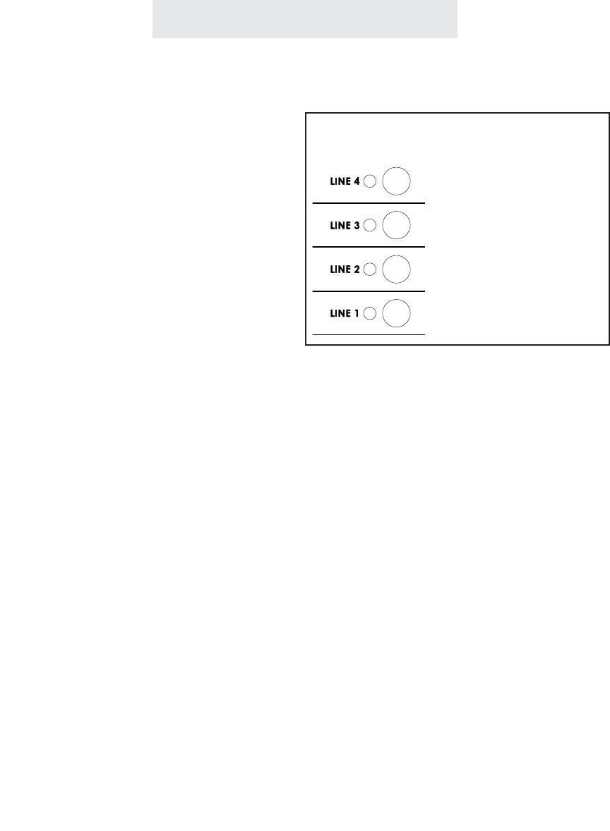
To program:
1 Press PROGRAM.
- The display will read “Program...”
2Press the soft key under NEXT
repeatedly, until ”Line Connections”
appears in the display, and then
press ENTER.
The display will show the current
line connection setting for Line 2.
3Press the soft key under CHANGE
repeatedly, until the desired line
connection setting for Line 2 is dis-
played.
The choices are:
L2: SHARED (factory setting)
L2: PRIVATE
L2: L2 AUX1
L2: UNCONNECTED
4Press the soft key under NEXT to
see the current setting for Line 3,
and repeat steps 3 and 4 to change
the settings for Lines 3-4.
5Press PROGRAM to exit.
Setting Up Private, Auxiliary and Unconnected Lines
While you must share the same Line 1 telephone
number at all the stations, you may choose to
leave some lines unconnected at particular sta-
tions or to connect private or auxiliary lines to
Lines 2, 3 or 4 at particular stations.
SHARED: This is the factory setting for all lines,
and is the setting you use if the particular line is
connected at this station to the same telephone
number as the corresponding line at the other
stations.
PRIVATE: Use this setting at any telephone that
is connected to a different telephone number
than the corresponding line at the other stations.
For example, you may connect your private tele-
phone number to Line 3 at your station instead of
connecting your station to the shared Line 3. In
this example, you would set Line 3 at your sta-
tion as PRIVATE.
AUX: Use this setting if two or more stations are
connected to a different telephone number than
the corresponding line at the other stations, but
they share the same number among them-
selves. For example, you may connect a group
of stations to a separate Line 3 telephone num-
ber than the rest of the system, yet they share
that same Line 3 telephone number among
themselves. In this example, you would set Line
3 at these stations to “L3 AUX1.”
Note that you can have up to one auxiliary Line
2, one auxiliary Line 3, and up to two auxiliary
Line 4’s.
UNCONNECTED: Use this feature at any tele-
phone that is not physically connected to all of its
lines. For example, you may install an EPIC 4-
line telephone in a room that is currently wired
for only lines 1, 2 and 3. In this example, you
would set Line 4 at this station as UNCON-
NECTED.
Setting Up Your System
ET4000 UG for PDF v8 062502.qxd 6/25/02 12:51 PM Page 29
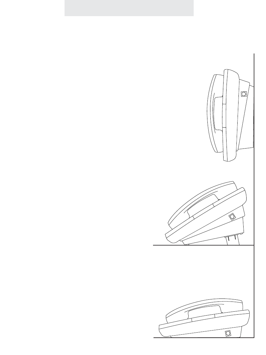
Operating Your System
Your EPIC telephone can be
placed on a desk or mounted
on a wall.
If you would like to wall mount your tele-
phone, please refer to the instructions
on page 6.
The wall mount bracket can also be
used as a desk pedestal. Simply attach
the bracket in the opposite direction that
you would for wall mounting, pressing
firmly upward to snap it in place, and
clip in the two supplied desk pedestal
feet.
Many people prefer the extra tilt provid-
ed by the pedestal, especially when the
phone is placed on a large desk.
You may choose to place your EPIC
telephone on a desk without the desk
pedestal. If you do so, set the desk
pedestal/wall mount bracket aside in
case you want to use it in the future.
20
Using the Desk Pedestal/Wall Mount Bracket
ET4000 UG for PDF v8 062502.qxd 6/25/02 12:51 PM Page 30
Operating Your System
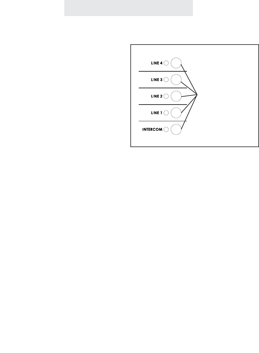
Indicator Light Description
Off Line is free
On steady (red) Line is in use at another station
On steady (green) Line is in use at your station
On steady (orange) Line is reserved at your station
Flashing slowly (orange) An outside call is ringing at your telephone
Flashing slowly (red) An outside call is ringing, but your ringer is Off,
Delayed, DND, or another call is already ringing
On (red) plus wink Call is on hold at another station
On (green) plus wink Call is on hold at your station
On (red) plus orange wink Call is on hold past reminder time at another ext.
On (green) plus orange wink Call is on hold past reminder time at your station
Note that the orange wink alerts everybody to a call that is still on hold past the reminder time.
Flashing quickly (red) Call is being transferred to all stations
Flashing quickly (green) Call is being transferred to your station
21
Line indicators
Intercom Indicator
Off Intercom is free
On steady (red) Intercom is in use at another station
On steady (green) Intercom is in use at your station
Flashing quickly (red) Someone is paging all stations
Flashing quickly (green) Someone is intercoming or paging your station
LCD Station In-Use Indicators
Off That station is free
On That station is in-use
ET4000 UG for PDF v8 062502.qxd 6/25/02 12:52 PM Page 31
Operating Your System
To choose how each line will ring:
1 Press PROGRAM.
- The display will read “Program...”
2 Press the soft key under NEXT repeat-
edly, until “Ringer Settings” appears in
the display, and then press ENTER.
3 The display will show the current ringer
setting for Line 1.
4Press the soft key under CHANGE
repeatedly, until the desired ringer set-
ting for Line 1 is displayed.
The choices are:
L1 Ringer: ON (factory setting)
L1 Ringer: DELAY
L1 Ringer: OFF
5 Press the soft key under NEXT to see
the current ringer setting for Line 2, and
repeat steps 4 and 5 to change the
ringer settings for Lines 2-4.
6 Press PROGRAM to exit.
Setting Ringers On/Delayed/Off
The ringers for each outside line are controlled
individually at each telephone. There are three
possible settings for each line ringer:
RINGER ON: The line will ring normally.
DELAYED RING: The line will start ringing after
the first 20 seconds. This is useful for an office
where a secretary usually answers the phone.
RINGER OFF: The line will not ring.
In all these cases, the line indicators will flash
normally to signal an incoming call, and you can
always answer that line, whether or not it is ring-
ing at your telephone, by pressing the corre-
sponding flashing line button.
Note: If you set a ringer ON or DELAYED, and a call comes in on that line while you are having
a conversation on another outside line, a double ring will sound every 15 seconds to alert you of
the incoming call. This feature, called “off-hook ringing”, can be turned off if you prefer. To do this,
press PROGRAM, then press the soft key under NEXT repeatedly until “Off Hook Ring” appears
in the display, along with the current setting. Press the soft key under CHANGE if you wish to
change the setting, and press PROGRAM to exit. Note that if a call comes in on one of the out-
side lines while you are engaged in an intercom call, there will never be any off hook ringing.
However the line lamps will flash normally to indicate an incoming call.
Each line ringer can be set individually.
An incoming call will flash
ORANGE at your tele-
phone...
...or RED if that line ringer
is off, delayed, your Do
Not Disturb is activated, or
another call has already
started ringing
ET4000 UG for PDF v8 062502.qxd 6/25/02 12:52 PM Page 32

To adjust the ringer volume:
While the phone is on-hook and idle:
1Press the up and down VOLUME
buttons to set desired ringer volume.
With each press, the phone will ring
once at the new volume.
To adjust the handset volume:
While using the handset:
1 Listen to dial tone or voice.
2 Press the up and down VOLUME
buttons to set desired handset
volume.
To adjust the speakerphone
volume:
While the speakerphone is activated:
1Listen to dial tone or voice.
2Press the up and down VOLUME
buttons to set desired speakerphone
volume.
To adjust the intercom speaker
volume:
While using the intercom or receiving a
page:
1Listen to the voice coming through
your speaker.
2Press the up and down VOLUME
buttons to set desired intercom
speaker volume.
Operating Your System
Adjusting Volume Levels
The Ringer, Handset, Speakerphone, Intercom
Speaker and Discrete Alert Volumes can all be
set independently by using the VOLUME but-
tons. To increase the volume, press the UP but-
ton. To decrease the volume, press the DOWN
button. Eight ringer, four handset, eight speak-
erphone, eight intercom speaker, and eight dis-
crete alert volumes are available.
The speaker volume levels for the intercom and
for outside calls are separate and independent of
one another. You may, for example, set your
speakerphone so that a caller’s voice will be at a
normal level, yet intercom pages will come
through at a louder volume.
To adjust the discrete alert volume:
While the phone is on-hook and idle:
1Press HOLD.
2Press the up and down arrows of the VOL-
UME button to set desired discrete alert vol-
ume. With each press, the phone will ring
once at the new discrete alert volume.
The discrete alert volume setting governs the
volume of off-hook ringing, off-hook intercom
ringing, the held call reminder, and the line
reserve alert.
23
Press to raise volume
Press to lower volume
ET4000 UG for PDF v8 062502.qxd 6/25/02 12:52 PM Page 33
Operating Your System
24
To set your system to Tone
or Pulse Dialing:
At Station #11:
1 Press PROGRAM.
- The display will read “Program...”
2 Press the soft key under NEXT
repeatedly, until “Advanced Setting”
appears in the display, and then
press ENTER.
3 Press the soft key under NEXT until
“Tone/Pulse” appears in the display,
and then press ENTER.
The display will show the current
tone/pulse setting
4 Press the soft key under CHANGE
repeatedly, until the desired
tone/pulse setting is displayed.
The choices are:
Dial: TONE (factory setting)
Dial: PULSE
5 Press PROGRAM to exit.
The Tone or Pulse dialing selection is made at
Station #11, and this setting governs the entire
system.
If any of your telephone lines have Pulse serv-
ice, you must select Pulse Dialing.
If all your lines have Tone Service, leave the set-
ting at Tone Dialing.
If your system is set to Pulse Dialing, you may
press the *button to change the dialing mode
temporarily to tone during a call.
This feature is useful if you have to send tone
signals for access to telephone banking, long
distance or other special services. Dialing mode
will revert to pulse when you hang up.
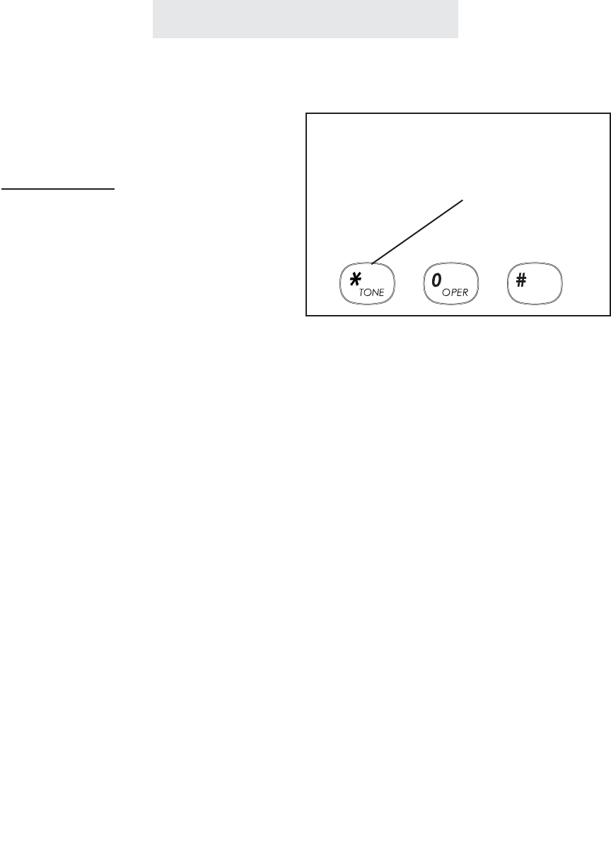
Making a Tone/Pulse Selection
Press the *button to send
tone signals if your system is
set to Pulse Dialing
ET4000 UG for PDF v8 062502.qxd 6/25/02 12:52 PM Page 34

To make and answer calls
using the handset:
1Lift the handset.
If you wish to override automatic line
selection, press desired LINE button
before lifting the handset.
2Replace the handset in the cradle to
hang up.
To make and answer calls
using the speakerphone:
1 Press the SPEAKER button to acti-
vate the speakerphone.
If you wish to override automatic line
selection, press the desired LINE
button instead of pressing the
SPEAKER button, and you will be
connected to that line on speaker-
phone.
2 Press SPEAKER again to hang up.
Operating Your System
25
Making and Answering a Call
When you lift the handset to make a call, the
phone selects a line according to its automatic
line selection setting. (See page 12.) If you lift
the handset while your phone is ringing, your
phone will automatically select the ringing line. If
you wish to override automatic line selection,
press the desired LINE button before lifting the
handset.
You can use the speakerphone to make or
answer an outside call, an intercom call or a
page. Simply press the SPEAKER button
instead of lifting the handset.
When you press the SPEAKER button to make a
call, the phone selects a line according to its
automatic line selection setting. (See page 12.)
If you press the SPEAKER button while your
phone is ringing, you will automatically answer
the ringing line. If you wish to override automat-
ic line selection, press the desired LINE button
instead of pressing the SPEAKER button, and
you will be connected to that line on the speak-
erphone.
During a call, you may switch back and forth
between handset and speakerphone as much as
you like. Simply press the SPEAKER button
while using the handset to activate the speaker-
phone and then hang up your handset. To
switch back to a handset call, lift the handset.
Note that whenever the SPEAKER indicator is
on, you may hang up the handset without dis-
connecting your call.
Note: You may make calls on either
handset or speakerphone using the
“predialing” feature. Many people find
this a convenient and relaxing method
of placing calls. See page 49 for details
on using the predialing feature.
ET4000 UG for PDF v8 062502.qxd 6/25/02 12:52 PM Page 35
Operating Your System
26
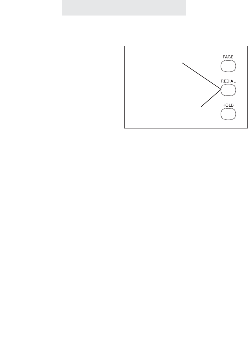
To redial the last phone num-
ber you dialed:
1 Go off-hook, either by lifting the
handset, pressing SPEAKER, press-
ing HEADSET, or by pressing the
desired LINE button.
2 Press REDIAL.
To redial any of the last five
phone numbers you dialed:
1 While the phone is on-hook and idle,
press REDIAL.
- The display will show the last num-
ber dialed, along with the time and
date of the call, and its duration.
2 Press the right arrow button under
the display to scroll through a list of
the last five numbers dialed, along
with the date, time and duration of
each call.
3 Go off-hook at any time to dial the
displayed number.
The Redial feature enables you to redial or sim-
ply view any of the last five telephone numbers
you dialed, along with the time, date and dura-
tion of each call.
Note that the redial feature is useful if you sim-
ply wish to review your recent calls, or if you
wish to know the duration of a particular call.
There is no need to actually dial the number.
Using Redial
Press REDIAL to
redial the last num-
ber you called
Press REDIAL and then
the right arrow button to
redial any of the last five
numbers you dialed
ET4000 UG for PDF v8 062502.qxd 6/25/02 12:52 PM Page 36

Operating Your System
27
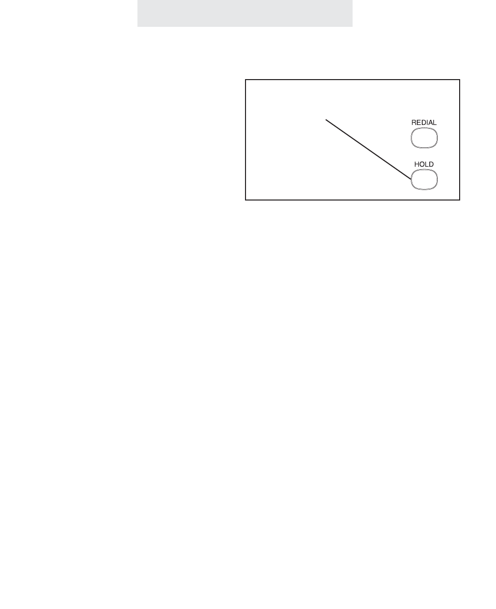
To put an outside call on hold:
1 Press HOLD.
2 To take the call off hold, press the
line button of the line on hold.
Note: Once a call is on hold,
it can be taken off hold by
any EPIC telephone.
While a caller is on hold, you can replace the
handset without disconnecting the call. Press
the LINE button at any time to return to your call.
Note: You cannot put an intercom call on hold.
If the call is still on hold at your telephone after
one minute, a triple ring will sound, and will
sound every minute thereafter to alert you that
the caller is still on hold.
Note: If you wish, you may change the first held
call reminder from two minutes to a different
time. (See Page 69.)
You can also take a call off from hold at a non-
EPIC telephone, by simply seizing the line at that
telephone.
Using Hold
Press HOLD to place an outside
call on hold
ET4000 UG for PDF v8 062502.qxd 6/25/02 12:52 PM Page 37
Operating Your System
28
To make a call on another line:
1 Press HOLD to place the first call on
hold.
2 Press another LINE button to make
a call on that line.
3 Press the LINE button of the first
call at any time to return to the first
call.
To answer a call ringing on
another line:
1 Press HOLD to place the first call on
hold.
2 Press the flashing LINE button to
answer the incoming call.
To switch between lines:
1Press HOLD to place your current
call on hold.
2Press another LINE button to make
or answer another call.
Using Another Line During a Conversation
While having a conversation on one line, you
may make a call on another line. Press HOLD to
place your first call on hold and then press
another LINE button to make a second call.
Press the first LINE button at any time to return
to your original call and disconnect the second
call. If you wish to keep the second call, you
must remember to place it on hold before return-
ing to the original call.
While having a conversation on one line, if a call
comes in on another line, its line lamp will begin
flashing and a double ring will sound every 15
seconds to alert you of that incoming call. If an
incoming call is ringing on a line that is set to
“ringer off” at your telephone, the alerting ring will
not sound.
You may answer the call by pressing the flashing
LINE button. Remember to put the first call on
hold before answering the incoming call, or the
first call will be disconnected.
You can switch between lines as much as you
want during the course of a call. Always remem-
ber to place your current call on hold before seiz-
ing another line, or you will disconnect your cur-
rent call.
Remember to put your current call
on hold before seizing another line
ET4000 UG for PDF v8 062502.qxd 6/25/02 12:52 PM Page 38
Operating Your System
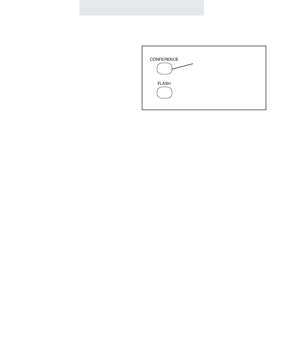
To conference two outside
calls:
1 Make or answer a call.
2 Press HOLD.
3Make or answer a call on another
line.
4When the second call is connected,
press the CONFERENCE button.
The lines are immediately confer-
enced.
5To end a conference call, hang up.
Both parties will be disconnected.
OR You may press a LINE button if
you wish to continue with the call on
that line. The party on the other line
will be disconnected.
To conference another station
while on an outside call:
1Place an intercom call to the desired
station. The outside call is automat-
ically placed on hold.
2 After the person at the other station
answers, press the CONFERENCE
button to create a conference call.
3 To end the conference call, hang up.
The person at the other station may
remain connected to the outside
call.
While having a conversation on one line, you
can make or answer a second call on another
line, then connect both lines together to create a
conference call.
If you wish to talk privately with one party during
a conference call, press HOLD to place both
lines on hold, and then press a LINE button to
talk privately with the person on that line. Press
CONFERENCE to resume the conference call.
You may also use the conference feature to join
another station to a call on an outside line. The
person at either EPIC telephone can leave the
conference call by hanging up, and the remain-
ing station will stay connected to the outside call.
Another way to conference another station to an
outside call is to tell the person at the other sta-
tion to press the appropriate LINE button at their
telephone. Note that if System Call Privacy is
ON, you must first turn Call Privacy OFF by
pressing the CONFERENCE button, or the per-
son at the other station will not be able join the
call by pressing their LINE button.
Conferencing Calls
29
The Conference button
allows you to join two
outside calls, or another
station to an outside call
ET4000 UG for PDF v8 062502.qxd 6/25/02 12:52 PM Page 39
Operating Your System
To transfer a call after first
announcing it to the other sta-
tion:
1Place an intercom call to the desired
station. The outside call is automat-
ically placed on hold.
2Wait for an answer. Announce that
you are transferring the call.
3Press the TRANSFER button.
To transfer a call directly,
without first announcing it to
the other station:
1 Press the TRANSFER button.
2 Dial the desired two-digit station
number to transfer the call to that
station.
30
You may transfer a call to another station after
first placing an intercom call to the desired sta-
tion to announce the call. If the person at the
other station wishes to talk to the caller, simply
press the TRANSFER button and hang up your
telephone. This feature is especially useful for
screening calls.
Note: If the other EPIC station does not wish to
be transferred the call, press the LINE button to
return to the outside call.
You may also transfer a call directly, without
announcing it to the other station. While the
desired station is ringing, the call will stay on
hold at all the other stations, including yours. If
the person at the desired station does not
answer, you can re-engage the call by pressing
the flashing LINE button. Likewise, if you hear
your telephone ringing the transfer ring and you
are nearer to another telephone, you can take
the call at this telephone simply by pressing the
flashing LINE button.
Note: If the desired station does not answer, it
will stop ringing after one minute.
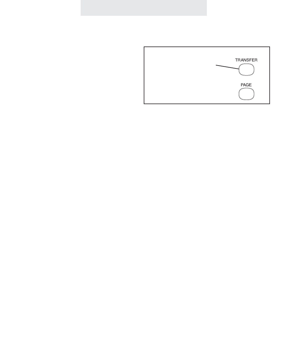
Transferring an Outside Call to Another Station
Press TRANSFER
to send a call to
another station
ET4000 UG for PDF v8 062502.qxd 6/25/02 12:52 PM Page 40

Operating Your System
To use the transfer ring:
1 Press TRANSFER twice.
All the other phones will now ring
with the transfer ring.
To use one of eight personal
rings:
1Press TRANSFER and then the
desired dial pad number buttons
(from 31-38).
All the other phones will now ring
with the personal ring represented
by that number.
31
Transferring an Outside Call to All Stations
You may transfer an outside call to all stations by
using the transfer ring or one of eight personal
rings. If you answer a call that is not for you, and
you do not know where to direct it, just press
TRANSFER twice. All of the other phones will
ring in the transfer ring and the call will be trans-
ferred to whoever answers next. The call will
remain on hold at your station until another sta-
tion picks up the call.
Your EPIC telephone also features eight unique
personal transfer rings which you may use to
transfer a call to all of the other stations. This
feature is helpful if you wish to transfer a call to
a particular person who may not always be by a
particular phone. Many people find this method
of transferring a call more professional and
unobtrusive than the traditional method of using
voice pages to call people to the phone. You
may assign each person their own personal ring,
and each time a call comes in for them, you can
transfer the call to all stations with their personal
ring.
Press TRANSFER twice
to transfer a call to all stations
Or use the dialpad num-
bers 31-38 to transfer a
call to all stations with a
personal ring
ET4000 UG for PDF v8 062502.qxd 6/25/02 12:52 PM Page 41
Operating Your System
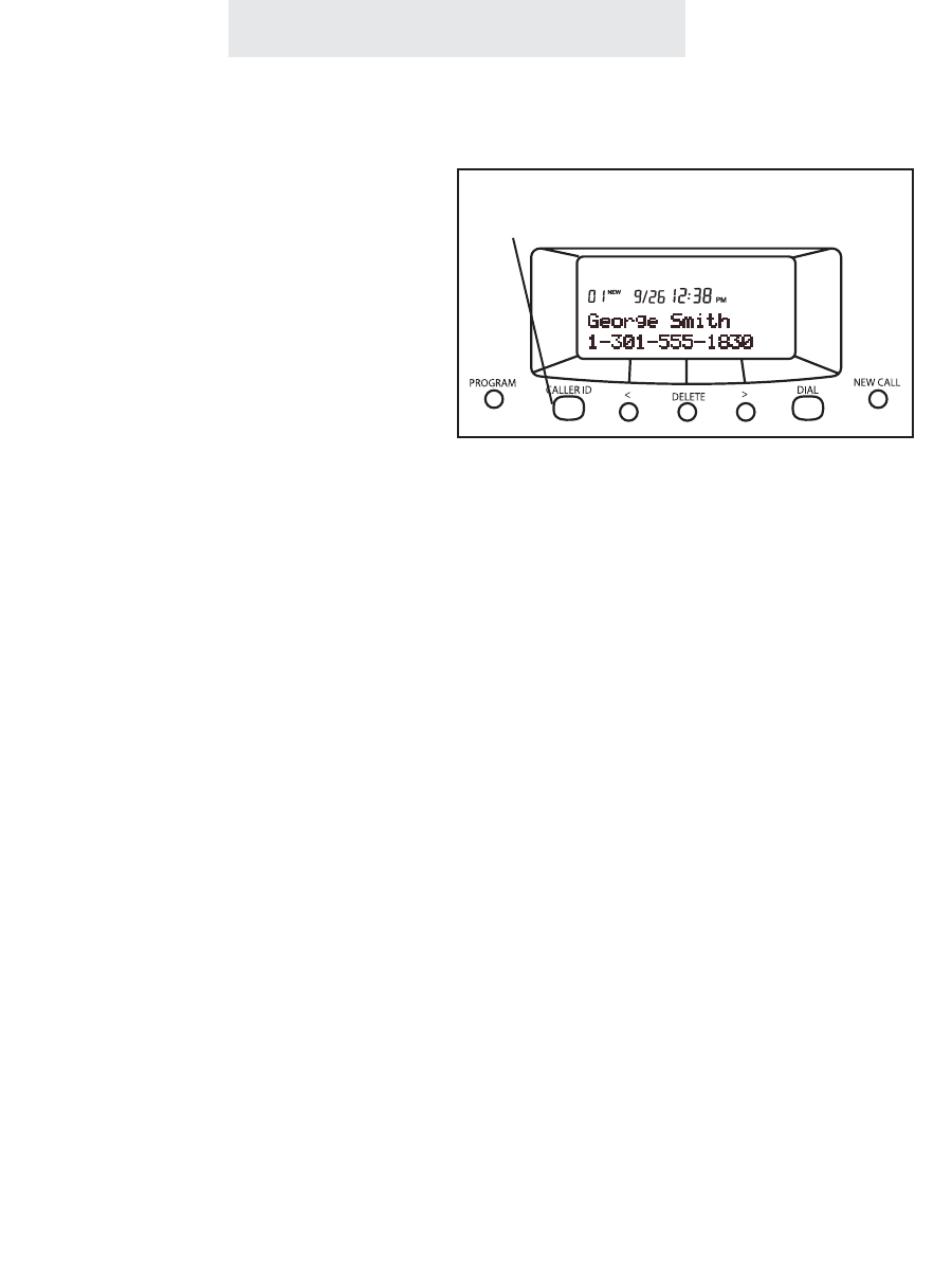
Using Caller ID
To see the caller ID informa-
tion of an incoming call:
The caller ID information will be dis-
played automatically, with no need to
press the CALLER ID button.
To use call waiting caller ID:
When you are on the line and another
call comes in, the display will automati-
cally display the caller ID information.
If you wish to answer that call, use the
FLASH button to toggle between the
calls.
To use the NEW CALL Lamp:
When the NEW CALL lamp is lit solid,
this means that at least one new call
has been added to the caller list since
the Caller ID button was last pressed.
Note that the NEW CALL lamp will
turn off as soon as you press the
Caller ID button, regardless of
whether you view the new calls or
not. Note also that if you answer a call
at your phone, it will not light the NEW
CALL lamp.
To view numbers in the caller
list:
1Press the CALLER ID button.
2 Use the right and left arrow buttons
under the display to view the caller
list.
The Caller ID feature works in conjunction with
Caller ID service, which may be offered by your
local telephone company, is name and number
and call waiting caller ID compatible, and can
store up to 50 of your most recent calls.
In order for this feature to work, you must sub-
scribe to the Caller ID service from your local
telephone company. Name and number caller
ID and call waiting caller ID may not be available
in all areas that offer caller ID service, and may
cost more than basic number caller ID service.
Note that you must order Caller ID service sepa-
rately for each line on which you want the serv-
ice.
If you subscribe to Call Waiting Caller ID com-
bined service, your telephone will let you see
who is calling while you are on another call.
Note that your telephone company must provide
this service in order for this feature to work.
When you press the CALLER ID button to view
the caller list, the display will indicate the number
of new calls in the caller list, as well as the total
number of calls in the caller list. A “new” call is
one that has not yet been viewed. You can then
use the right arrow button to view the list from
most recent to oldest, or the left arrow button to
go from the oldest to the most recent calls.
Press CALLER ID and the arrow buttons
to view the caller list
ET4000 UG for PDF v8 062502.qxd 6/25/02 12:52 PM Page 42

Operating Your System
Using Caller ID (Continued)
To dial a number in the caller list:
1Follow the instructions on the previous
page for viewing the caller list.
2 Lift your handset, or press DIAL, or
SPEAKER, or HEADSET, or a LINE but-
ton when the desired number is dis-
played.
Note that before performing step 2, you
may press the “#” button repeatedly to
scroll through different choices for dialing
that number, either with our without the
area code or a “1” in front.
To delete numbers from the caller
list:
1While viewing the caller list, press the
DELETE button twice when the desired
number is displayed,
OR
press the DELETE button and keep it
depressed for 5 seconds to delete all
the numbers in the caller list.
Note: In addition to being able to delete
any and all records from your caller list, you
can decide whether calls are stored in the
first place. You may choose separately for
each line at your phone. To do this, press
PROGRAM, then NEXT until you see
“Caller ID Store”, then press ENTER. Press
CHANGE if you wish to change the setting
for Line 1, and then press NEXT and
CHANGE to view and change the settings
for Lines 2-4.
When you dial a number from the caller list, the
telephone will dial it as it is shown in the display,
with a “1” and the area code. If you need to dial
it in a different way, press the “#” button to scroll
through different choices for dialing the number
before going off-hook or pressing DIAL.
Entering Area Codes into your Epic
telephone
You may also enter area codes into your EPIC
telephone so that telephone numbers are dis-
played properly, enabling you to dial numbers in
the caller list without having to press the “#” but-
ton first.
You may enter one HOME area code. Use this
feature if you only need to dial the seven digits of
the telephone numbers for calls in your own area
code. After you program your home area code,
when you receive a call from within this area
code, the screen will display only the seven dig-
its, and only those seven digits will be dialed out.
You may also enter up to six LOCAL area codes.
Use this feature if there are certain area codes
that require you to dial the area code plus the
seven digits, but without the “1” in front.
In addition, you may enter up to six “1 PLUS 7”
area codes. Use this feature if there are certain
area codes that require you to dial a “1” plus the
seven digits, but without the area code.
To enter your HOME, LOCAL, and “1 PLUS 7”
area codes, press PROGRAM, then press NEXT
until you see “Area Codes” in the display, then
press ENTER. You will see the HOME area code
setting. Press CHANGE if you wish to change
this setting, or press NEXT to view the LOCAL
and “1 PLUS 7” area code settings. Press
CHANGE whenever you wish to enter a new
code or change a currently stored code.
ET4000 UG for PDF v8 062502.qxd 6/25/02 12:52 PM Page 43

Operating Your System
Using Telephone Company Voice Mail
To use your NEW CALL lamp to
indicate voice mail messages:
1Subscribe to voice mail service from
your local Telephone Company.
2Follow the instructions at right to set
your voice mail detector to the proper
line.
- The NEW CALL lamp will now flash
whenever you have new messages.
To access your voice mail mes-
sages:
1Dial the number for your Telephone
Company voice mail service. You
may wish to store this number in one
of your phone’s memory locations for
easy access (see page 45).
To turn off the NEW CALL lamp:
If your NEW CALL lamp ever remains
flashing even after you have retrieved
your messages, you may turn it off manu-
ally by following the following instructions:
1 Press PROGRAM.
- The display will read “Program...”
2 Press the soft key under NEXT until
“New Call Lamp and VMWI Message”
appears in the display.
3 Press the soft key under RESET.
If you subscribe to Telephone Company voice
mail, the NEW CALL lamp will flash when you
have unretrieved messages.
Your telephone comes factory-set to detect mes-
sages on Line 1. If your voice mail service is on
one of the other lines, you may change this set-
ting to the proper line. You may also turn the
feature off if you prefer.
To do this, press PROGRAM, then NEXT repeat-
edly until you see “Phone Co VMWI” in the dis-
play, then press ENTER. The display will read
“VMWI: LINE 1.” Press CHANGE if you wish to
select LINE 2, LINE 3, LINE 4, or OFF.
Message signals are sent by the Telephone
Company in one of two ways: FSK or stutter dial
tone. Your telephone comes factory-set to FSK,
which means that only its FSK detector is active.
If your NEW CALL lamp functions properly, then
do not change this setting. However, if your NEW
CALL lamp does not flash when you have unre-
trieved messages, and yet you hear the stutter
dial tone when you pick up your handset, first
make sure you have followed the above steps to
make sure you have set the detector to the line
that your voice mail service is on.
If your NEW CALL lamp still does not function
properly, then set your detector to STUTTER.
To do this, follow the above steps to set the prop-
er line, then press NEXT. The display will read
“VMWI: FSK.” Press CHANGE if you wish to
select STUTTER. This will activate the stutter
dial tone detector.
34
ET4000 UG for PDF v8 062502.qxd 6/25/02 12:52 PM Page 44
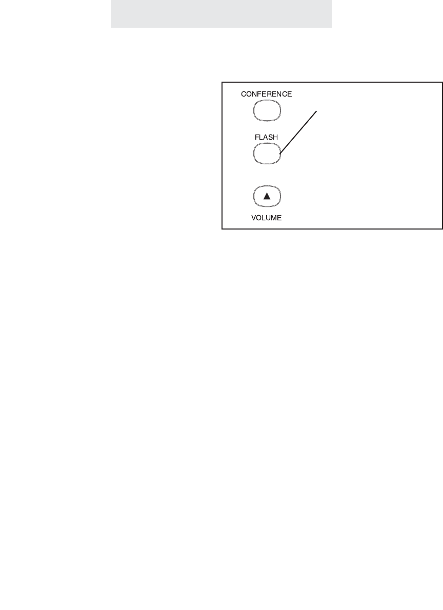
Using Flash
Operating Your System
1 Press FLASH instead of the switch-
hook when using custom calling
services or when activating certain
Centrex or PBX features.
Press the FLASH button instead of pressing the
switchhook to activate services such as Call
Waiting or 3-Way Calling, or to activate certain
PBX or Centrex features. You may be required
to press other buttons before or after you press
FLASH. Refer to the custom calling instructions
provided by your local telephone company or to
the operating instructions provided with your
PBX.
You can store a switchhook flash into a memory
location. When you store a flash, it is represent-
ed in the display by a small “f”. (See page 48.)
Note: The initial factory-set flash length is 700
milliseconds, which is appropriate for most
installations. However, you can adjust the flash
length to make it longer or shorter. (See page
71.)
35
Press FLASH to access
custom calling services
such as Call Waiting
ET4000 UG for PDF v8 062502.qxd 6/25/02 12:52 PM Page 45
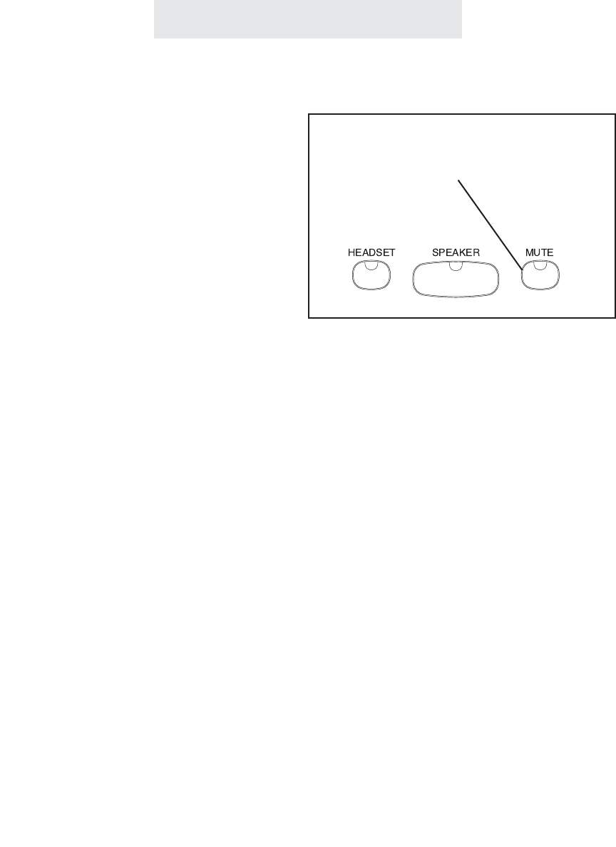
Using Mute
Operating Your System
To turn mute on/off during a
call:
1Press MUTE.
- The MUTE indicator turns ON.
2Press MUTE again to cancel MUTE.
- The MUTE indicator turns OFF.
The Mute feature allows you to turn off your tele-
phone’s microphone so that the other party can-
not hear you.
The Mute feature works whether you are using
the handset or the speakerphone. It silences
only your voice; you will still be able to hear the
other party.
The Mute feature automatically cancels when
you hang up, switch between lines or switch from
speakerphone to handset during a call.
36
Press MUTE to turn off your microphone
so you cannot be heard
ET4000 UG for PDF v8 062502.qxd 6/25/02 12:52 PM Page 46
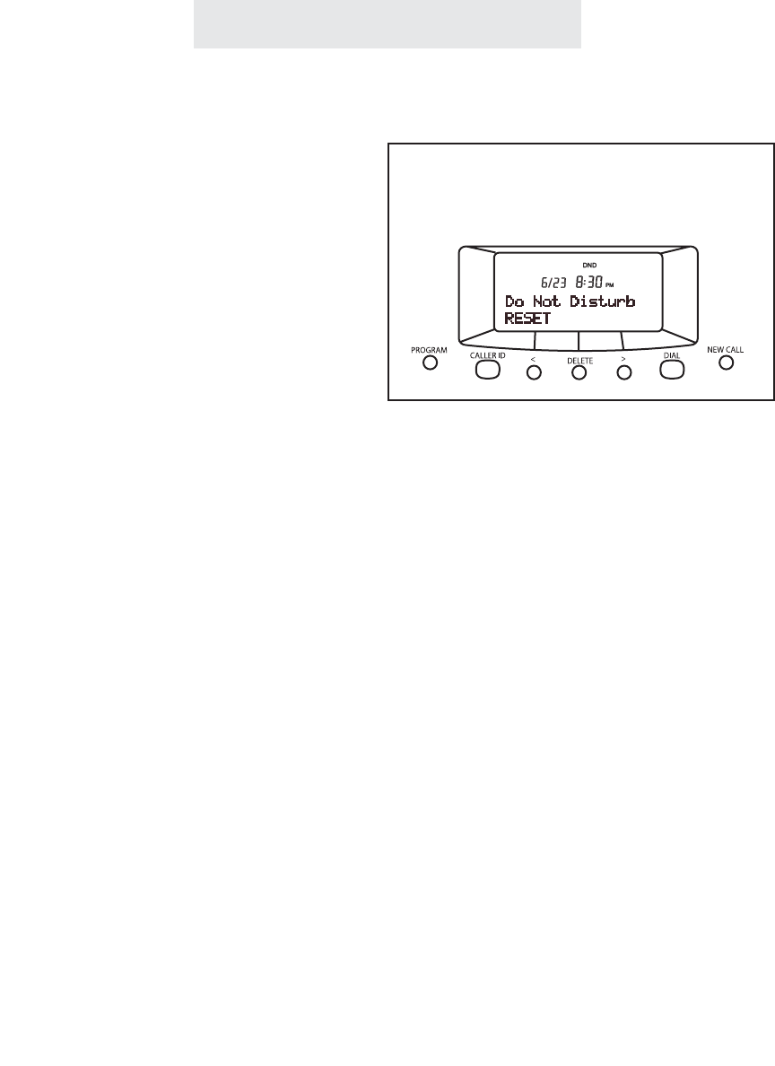
Operating Your System
Using Do Not Disturb (DND)
To activate Do Not Disturb:
1 Press PROGRAM.
- The display will read “Program...”
2 Press the soft key under NEXT
repeatedly, until “Don’t Dsturb:OFF”
appears in the display.
3 Press the soft key under CHANGE.
The display will now read “Don’t
Dsturb:ON”.
4 Press PROGRAM to exit.
You will notice that your phone’s DND
indicator in the display is now on, and
your telephone’s display will read “Do
Not Disturb.”
To cancel Do Not Disturb:
Press the soft key under RESET at any
time to cancel Do Not Disturb.
The Do Not Disturb feature is useful to prevent
interruptions during meetings or whenever you
do not want to be disturbed.
While the Do Not Disturb feature is activated,
your telephone will not ring. Incoming calls will
be signaled only by the LINE indicators flashing.
Pages will not be heard through your telephone,
and other stations will be unable to make inter-
com calls to you or transfer calls to your tele-
phone.
You may still answer any outside call by pressing
the desired flashing LINE button. You may also
place outside calls and intercom calls while your
Do Not Disturb is activated.
37
Activate Do Not Disturb to silence your
ringer and prevent intercom calls and pages
ET4000 UG for PDF v8 062502.qxd 6/25/02 12:52 PM Page 47
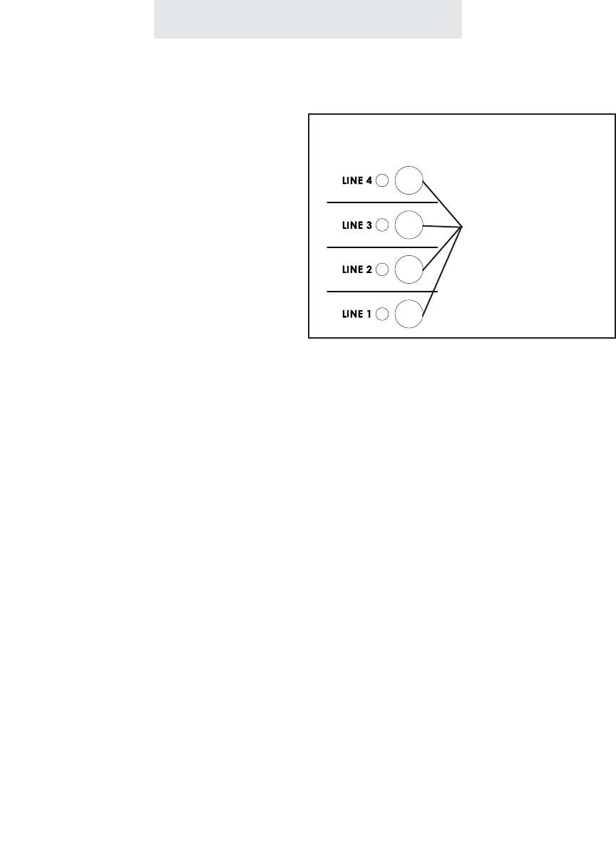
Operating Your System
Using Line Reserve
To reserve a line that is cur-
rently being used:
While the phone is on-hook and idle:
1Press HOLD.
2Press the desired LINE button.
- The line indicator will turn from red
to orange.
To cancel Line Reserve:
1Press the LINE button again.
- The line indicator will turn from
orange back to red.
The Line Reserve feature enables you to reserve
a line that is currently in use. This feature is
especially useful in offices where the phones are
in heavy use. You are spared the trouble of con-
stantly monitoring your telephone while waiting
for a free line.
To reserve a line that someone is using, press
HOLD then the desired LINE button. As soon as
that line becomes free, your phone will alert you
with a triple ring and that line will be reserved for
your station.
If you do not go off-hook within 15 seconds after
you are alerted, the line will become free again
for others to use, and your Line Reserve will also
cancel automatically if you make or answer a call
on another line.
38
press the desired
LINE button to
reserve a line
currently in use
Press HOLD then...
ET4000 UG for PDF v8 062502.qxd 6/25/02 12:52 PM Page 48
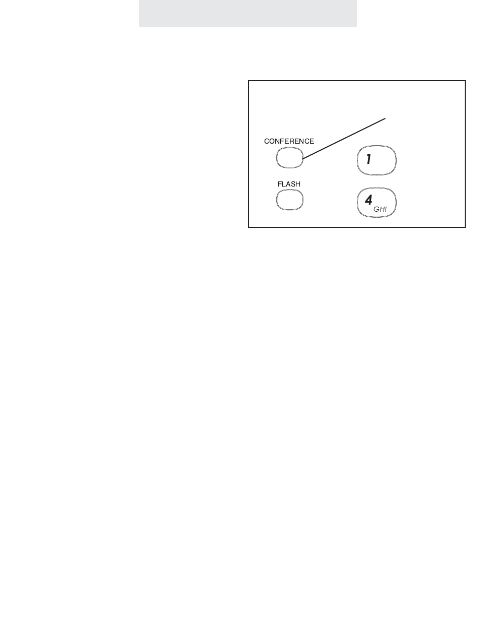
Operating Your System
39
The Call Privacy feature prevents people at
other stations from joining or listening to your
conversation unless you conference them to the
line or release the call privacy during the call.
When you use a telephone line, Call Privacy will
automatically be on or off, depending on the sys-
tem setting which was set at Station #11. (See
page 18.)
If you release Call Privacy during a call, this new
setting will remain for the length of the call, and
the setting will automatically return to the system
setting when you hang up.
Note: Call Privacy is always on for intercom
calls.
Releasing Call Privacy
To release call privacy during
a call:
If your system is set to have call priva-
cy normally ON, it will automatically be
on during each call.
1Press the CONFERENCE button
any time you wish to turn the call
privacy OFF during a particular call.
“Privacy Released” will appear in
the display to indicate that call priva-
cy is temporarily off.
The CONFERENCE button is also used
to release Call Privacy off during a call
ET4000 UG for PDF v8 062502.qxd 6/25/02 12:52 PM Page 49
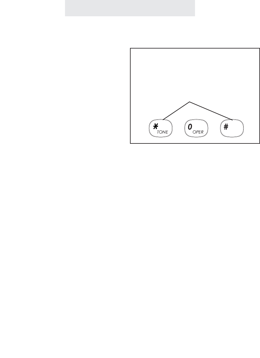
To temporarily turn off toll
restriction at a restricted
telephone:
1Press HOLD.
2Enter the 4 digit toll restriction access
code which was set at Station #11. If
no code was set, the access code is
the initial number set at the factory,
which is “1234”.
The SPEAKER light will flash indicat-
ing that toll restriction is temporarily
off, and you may make your call.
To turn toll restriction on/off at
a particular telephone for a
longer period:
1Press HOLD.
2Enter “*” or “#”.
*... to turn Toll Restriction ON.
# ... to turn Toll Restriction OFF (fac-
tory setting).
3Enter the 4 digit toll restriction access
code which was set at Station #11. If
no code was set, the access code is
the initial number set at the factory,
which is “1234”.
Operating Your System
Using Toll Restriction
You may sometimes wish to make an unrestrict-
ed call from a restricted telephone. When you
use this feature, Toll Restriction will turn back on
automatically 10 seconds after you hang up and
will be signaled by a flash of the SPEAKER light.
You may continue making unrestricted calls with-
out the need of re-entering the access code, as
long as you go off-hook again within 10 seconds
of hanging up your previous call.
You may turn Toll Restriction ON and OFF at a
telephone without affecting the Toll Restriction
settings stored in that telephone. For instance,
you may wish to turn Toll Restriction off for some
guests, or you may want Toll Restriction to be on
only during certain periods. When you turn off
Toll Restriction at a telephone using this feature,
it will stay off until you turn it back on.
Note: Turning Toll Restriction ON at a telephone
will have no effect unless restrictions have been
stored at that telephone. (See pages 14-17.)
40
Press HOLD then the four-digit
access code to temporarily turn
off Toll Restriction at a telephone
Use the *and # buttons if you wish to turn
Toll Restriction on or off at a telephone for
a longer period
ET4000 UG for PDF v8 062502.qxd 6/25/02 12:52 PM Page 50
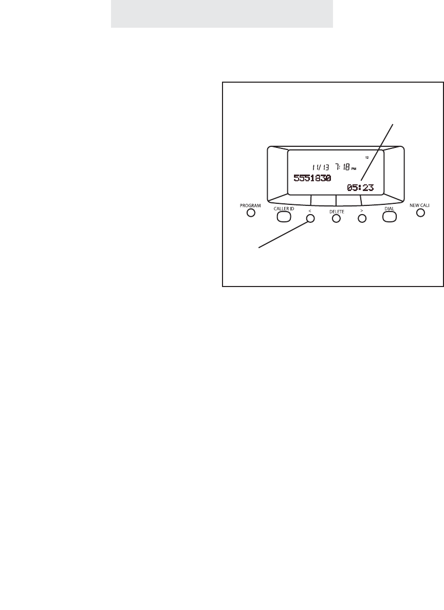
Using the Call Timer
Operating Your System
To view the elapsed time dur-
ing your call:
Simply view the display, which will auto-
matically display the elapsed time dur-
ing a call.
To restart the timer from zero:
Press the left arrow (<)button, which is
found directly below the display.
To view the length of your pre-
vious five calls:
While the phone is on-hook and idle,
press REDIAL. The display will show
the elapsed time of the previous call,
along with its time and date.
Note that you can use the right arrow
button under the display to view the
lengths of the previous five calls, along
with their times and dates.
Every call is automatically timed in minutes and
seconds. This feature is great for account billing
and controlling long distance usage.
The minutes and seconds display appears auto-
matically, showing the elapsed time of the call. If
you wish to begin counting the time from that
instant, press the left arrow button to restart the
timer from zero.
41
The call timer automatically displays
the elapsed time during your call
Press the left arrow button at any time
to restart the timer from zero
ET4000 UG for PDF v8 062502.qxd 6/25/02 12:52 PM Page 51
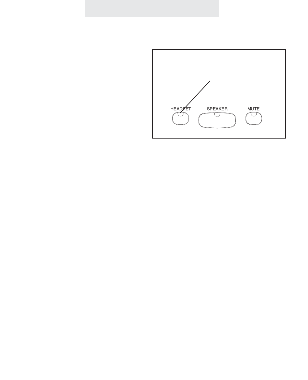
Using a Headset With Your EPIC Telephone
To make and answer a call
using the headset:
1Press the HEADSET button to acti-
vate the headset.
If you wish to override automatic line
selection, press the desired LINE
button instead of pressing the
HEADSET button, and you will be
connected to that line on the speak-
erphone. Then press the HEADSET
button to toggle to the headset.
2Press HEADSET again to hang up.
Note: We recommend that you use
only the headset that TMC offers as an
accessory for the Epic System, model
number HS-8200, which has been test-
ed to function properly with your tele-
phone. You may purchase this headset
from wherever you purchased your
telephones, or by calling TMC directly
at 1-800-TMC-1638.
Your EPIC telephone is headset-ready. It comes
equipped with a 2.5mm headset jack, and a
built-in headset amplifier, along with a dedicated
HEADSET button
Simply plug the accessory telephone headset
with a 2.5 millimeter plug into the headset jack,
and you are all set. There is no need to buy a
headset with a separate amplifier.
You can use your headset to make or answer an
outside call, an intercom call or a page. Simply
press the HEADSET button instead of lifting the
handset.
During a call, you may switch back and forth
between handset and headset and speaker-
phone as much as you like.
Note that whenever the HEADSET indicator is
on, you may hang up the handset without dis-
connecting your call.
Use the HEADSET button to toggle
the headset on and off.
Operating Your System
42
ET4000 UG for PDF v8 062502.qxd 6/25/02 12:52 PM Page 52
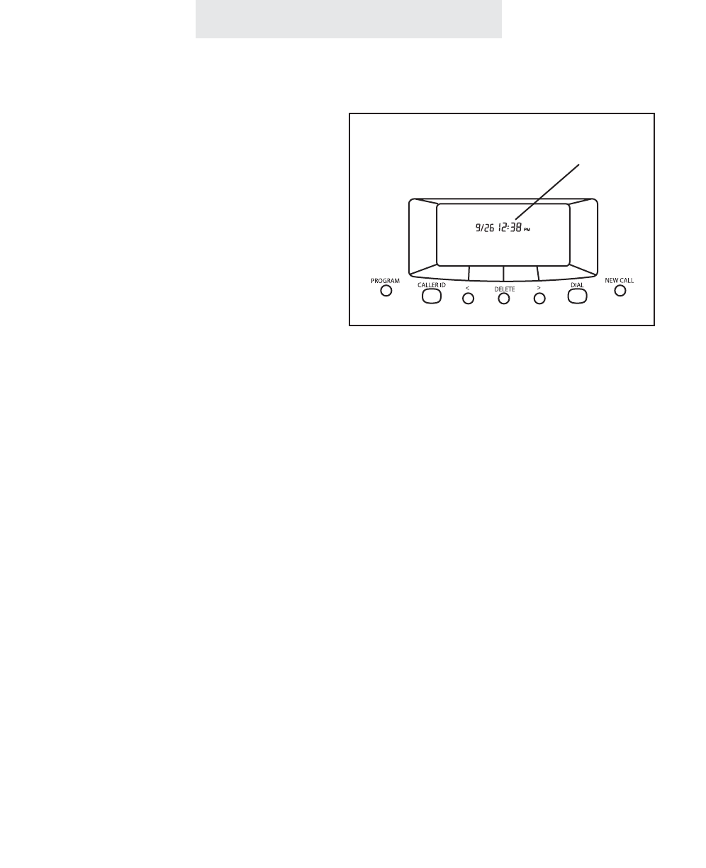
Operating Your System
1 Press PROGRAM.
- The display will read “Program...”
2 Press the soft key under NEXT
repeatedly, until “Time/Date Set”
appears in the display, and then
press ENTER.
The display will show the currently
set time.
3 Press the soft key under CHANGE,
then enter the time as instructed in
the display.
4 Press the soft key under NEXT, then
press CHANGE to choose between
AM or PM, then press NEXT again.
The display will show the currently
set date.
5 Press the soft key under CHANGE,
then enter the date as instructed in
the display.
6 Press PROGRAM to exit.
Follow these same steps whenever you wish to
adjust your system’s clock.
Note: If you subscribe to caller ID service
from your local telephone company, then
there is no need to set the time and date for
your telephone. This will be set automatical-
ly by the caller ID information, and will be
updated as new calls come in.
Adjusting Your Telephone's Time and Date
43
If you subscribe to Caller ID service, then
the Date and Time is set automatically
ET4000 UG for PDF v8 062502.qxd 6/25/02 12:52 PM Page 53
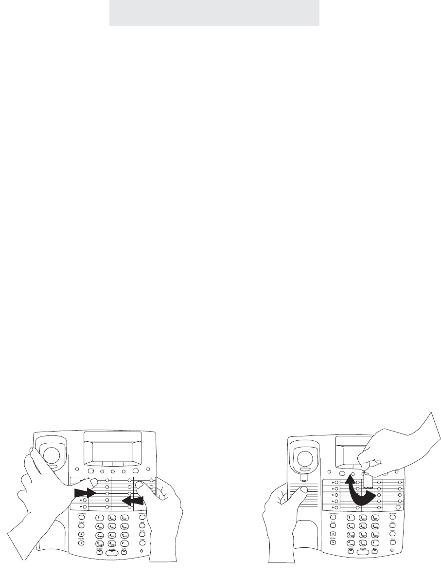
Memory Dialing
Memory Features
Your EPIC telephone can store up to 78 of your most often dialed numbers in its
memory.
- 14 numbers into Upper Memory locations, which you can dial at the touch of a
memory button;
- 14 numbers into Lower Memory locations, which you can dial by pressing
LOWER plus the desired memory button;
- 10 numbers into Personal Directory locations, which you can dial by press-
ing”#” followed by the arrow buttons and the DIAL button;
- 40 numbers into Shared Directory locations, which you store at Station #11 and
which you can dial from any phone in the system by pressing “*” followed by
the arrow buttons and the DIAL button.
Directory Card
Remove the directory card and write down the names or telephone numbers
associated with the memory locations where you are storing numbers.
To remove the directory card, press inward with both thumbs and lift the bowed
plastic as shown below, or simply touch the directory card with a piece of scotch
tape and lift upward, as illustrated below right.
PROGRAM CALLER ID <
LINE 4
LINE 3
LINE 2
LINE 1
INTERCOM LOWER
>DIAL
DELETE NEW CALL
PROGRAM CALLER ID <
LINE 4
LINE 3
LINE 2
LINE 1
INTERCOM LOWER
>DIAL
DELETE NEW CALL
44
ET4000 UG for PDF v8 062502.qxd 6/25/02 12:52 PM Page 54
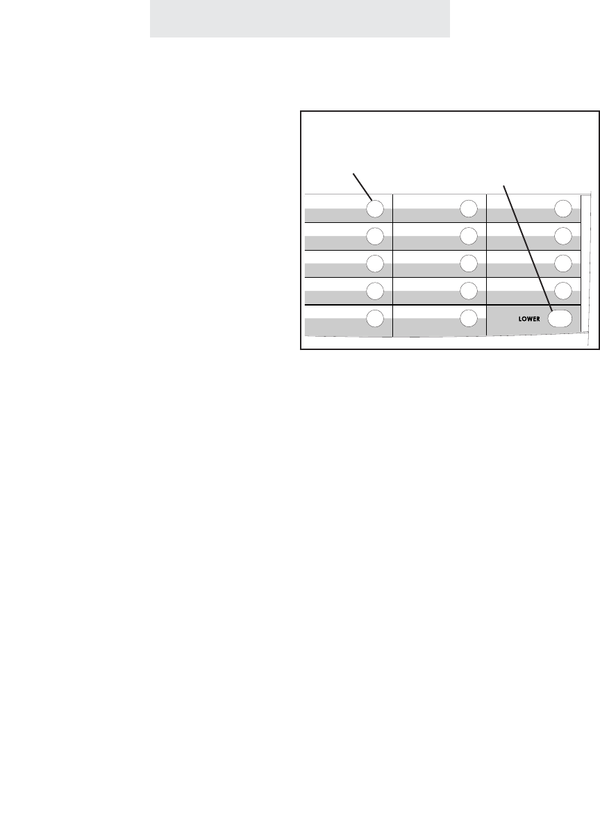
Memory Dialing
Using Memory Dial
To store a memory dial num-
ber:
1 Press PROGRAM.
- The display will read “Program...”
2 Press the soft key under MEM.
- The display will read “Select
Location”
3 Press the Memory button where you
wish to store the number, or press
LOWER followed by the desired
memory button if you wish to store
the number in a lower memory loca-
tion.
- The display will show the currently
stored number, or indicate “Empty
Location.”
4Press the soft key under CHANGE if
you wish to store a new number.
5 Dial desired telephone number, up
to 32 digits.
6 Press the soft key under SAVE.
You may store up to 28 telephone numbers at
your telephone which you can dial automatically
with the press of a memory button.
Note that you can enter hyphens in your num-
bers for easy reading, as well as flashes and
pauses (see page 48).
To dial a memory dial number:
1 Press the memory button where the desired
telephone number is stored.
OR
Press LOWER followed by the desired
memory button if you wish to dial a number
stored in a lower memory location.
When you press a memory button, the speaker-
phone turns on automatically, and the number is
dialed out. You may lift the handset or press
HEADSET to switch to a handset or headset call
at any time.
Press Memory
button to dial
numbers in white
spaces
Press LOWER,
then Memory button
to dial numbers in
gray spaces
45
Note: If you ever wish to erase the
memory dial numbers stored in your
phone, please follow the instructions
found on page 49.
ET4000 UG for PDF v8 062502.qxd 6/25/02 12:52 PM Page 55

Memory Dialing
To store a personal directory
dial number:
1 Press PROGRAM.
- The display will read “Program...”
2 Press the soft key under MEM.
- The display will read “Select
Location”
3Press the “#” button.
- The display will read “ Empty
Location,” or indicate that your
personal directory is full.
4Press the soft key under CHANGE if
you wish to store a new number, or
press NEXT repeatedly until you
see the previously stored entry you
would like to change, and then
press CHANGE.
5Dial desired telephone number, and
then press NEXT.
- The display will show the currently
stored name, or indicate “No
Name.”
6Press the soft key under CHANGE if
you wish to store a new name, and
then use the dialpad numbers and
the soft keys to enter the name to
go along with the telephone number.
7 Press the soft key under SAVE.
You may store up to 10 personal directory dial
telephone numbers at your telephone.
Note that you can enter hyphens in your num-
bers for easy reading, as well as flashes and
pauses (see page 48).
For a guide on using the dialpad to enter names,
please see page 57.
If you would like to erase the personal directory
numbers stored in your phone, please follow the
instructions found on page 49.
To dial a personal directory number:
1 While the phone is on-hook and idle, press
the “#” button.
- The display will read “Personal Dir.”
2 Use the right and left arrow buttons below
the display to view the personal directory
entries.
Note: The directory is organized alphabeti-
cally, and you may jump to your desired
entry, or one close to it, by pressing the cor-
responding dialpad number. For example,
press the “5” dialpad button three times to
jump to the first entry starting with “L”. You
can then use the right and left arrow buttons
if needed to view the entries starting at that
point.
3 When the desired entry is displayed, you
may dial it simply by lifting your handset, or
by pressing DIAL, or SPEAKER, or HEAD-
SET, or by pressing a desired LINE button.
Using Personal Directory Dial
46
ET4000 UG for PDF v8 062502.qxd 6/25/02 12:52 PM Page 56

Memory Dialing
Using Shared Directory Dial
To store a shared directory
dial number:
At Station #11:
1 Press PROGRAM.
- The display will read “Program...”
2 Press the soft key under MEM.
- The display will read “Select
Location”
3Press the “*” button.
- The display will read “ Empty
Location,” or indicate that the
shared directory is full.
4Press the soft key under CHANGE if
you wish to store a new number, or
press NEXT repeatedly until you
see the previously stored entry you
would like to edit, and then press
CHANGE.
5Dial desired telephone number, and
then press NEXT.
- The display will show the currently
stored name, or indicate “No
Name.”
6Press the soft key under CHANGE if
you wish to store a new name, and
then use the dialpad numbers and
the soft keys to enter the name to
go along with the telephone number.
7 Press the soft key under SAVE.
Note: After you store a shared directory dial number at station #11, please
allow 24 hours for it to be shared with the other stations in the system.
47
The Shared Directory Dial feature allows you to
store an additional 40 telephone numbers into
memory at Station #11 and dial them from any
phone in the system.
Note that you can enter hyphens in your num-
bers for easy reading, as well as flashes and
pauses (see page 48).
For a guide on using the dialpad to enter names,
please see page 57.
If you would like to erase the shared directory
numbers, please follow the instructions found on
page 49.
To dial a shared directory number:
1 While the phone is on-hook and idle, press
the “*” button.
- The display will read “Shared Directory”
2 Use the right and left arrow buttons below
the display to view the shared directory
entries.
Note: The directory is organized alphabeti-
cally, and you may jump to your desired
entry, or one close to it, by pressing the cor-
responding dialpad number. You can then
use the right and left arrow buttons if need-
ed to view the entries starting at that point.
3 When the desired entry is displayed, you
may dial it simply by lifting your handset, or
by pressing DIAL, or SPEAKER, or HEAD-
SET, or by pressing a desired LINE button.
ET4000 UG for PDF v8 062502.qxd 6/25/02 12:52 PM Page 57

Memory Dialing
Storing a hyphen into memory:
You can store hyphens in your memory dial numbers for easy reading. To insert a hyphen into a
number you are storing, press PAGE. Each press of PAGE will insert a hyphen.
Storing a dialing pause into memory:
You can store a pause in a memory location for use with certain banking and long distance serv-
ices. You may also need to insert a pause between the access number and the telephone num-
ber if your telephone is connected to a PBX or Centrex system. To insert a dialing pause into a
number you are storing, press HOLD. Each press of HOLD will insert a 1.5 second pause, rep-
resented by a “p” in the display.
Storing a switchhook flash into memory:
You can store a switchhook flash into a memory location for use with certain custom calling serv-
ices, such as Call Waiting. You may also need to insert a switchhook flash as part of a feature
activation code if your telephone is connected to a PBX or Centrex system. To insert a switch-
hook flash into a number you are storing, press FLASH. Each press of FLASH will insert a 700
millisecond switchhook flash, represented by an “f” in the display. Note: if 700 ms is not an appro-
priate length for your installation, you may set a different value. (See page 71.)
Storing temporary tone dialing into memory:
If your system is set to pulse dialing mode, you can store a temporary switch to tone dialing as
part of a number you are storing in a memory location. You may, for example, wish to dial a num-
ber in pulse followed by an access code in tone dialing. To insert a “switch to tone” into a
sequence you are storing, press the *(TONE) button. All the following numbers in the sequence
will automatically be dialed in tone mode.
48
Special Memory Features
ET4000 UG for PDF v8 062502.qxd 6/25/02 12:52 PM Page 58

Storing one of the last five numbers dialed into memory:
To store a redial number into memory, follow the instructions for entering a number into memory,
except simply press REDIAL instead of manually dialing a number. You may then press the soft
key under SCROLL to scroll through the last five numbers dialed. Press SAVE when the desired
number is displayed.
Storing a Caller ID number into memory:
To store a caller ID number into memory, follow the instructions for entering a number into mem-
ory, except simply press CALLER ID instead of manually dialing a number. You may then press
the soft key under SCROLL to scroll through the caller ID list. Press SAVE when the desired num-
ber is displayed. Note that you can store caller ID names and numbers into private and shared
directories as well into memory button locations.
Predialing:
You may predial a call, which allows you to casually enter a telephone number and check it in the
display before it is dialed out. To make a predialed call, enter the number using the dialpad while
the telephone is on-hook, then lift the handset or press the SPEAKER or HEADSET button or
press the desired LINE button. If you make a mistake while dialing the number, you can use the
DELETE button to erase digits one at a time.
Erasing numbers stored in memory:
To erase all memory dial numbers and personal directory numbers stored in your tele-
phone, press PROGRAM, then press the soft key under NEXT repeatedly, until “Advanced
Setting” appears in the display, and then press ENTER. “Erase Memory” will appear in the dis-
play. Press ENTER. “Memory Dials” will appear in the display. Press the soft key under ERASE.
After a brief pause, the display will read “Erasing Done!” To erase the shared directory num-
bers, at station #11 follow the above steps until you see “Memory Dials” in the display. Press
NEXT, and you will see “Shared Directory” in the display. Press the soft key under ERASE. After
a brief pause, the display will read “Erasing Done!” To erase the toll restrictions stored in your
telephone follow the above steps until you see “Erase Memory” in the display. Press NEXT
repeatedly, until you see “Erase Toll Restr” in the display, and then press ENTER. If you are not
at station #11, you will be prompted to enter the toll restriction access code. Do this, then press
the soft key under ERASE. After a brief pause, the display will read “Erasing Done!”
Memory Dialing
Special Memory Features (Continued)
49
ET4000 UG for PDF v8 062502.qxd 6/25/02 12:52 PM Page 59
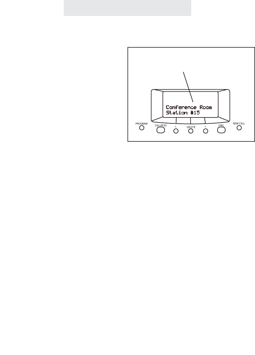
To intercom another station:
1Press the INTERCOM button, then
dial the two-digit station number of
the station you wish to intercom.
2To end the conversation, hang up or
press the SPEAKER button.
To intercom another station while
you are on an outside call:
1Press the INTERCOM button. The
outside call is automatically placed
on hold.
2Place your intercom call the same
way as described above.
3Press the LINE button of your out-
side call at any time to return to that
call.
Intercom Operation
50
Making Intercom Calls
You may place an intercom call by dialing the
two-digit station number of the desired station.
When you place an intercom call, your speaker-
phone turns on automatically.
If the called station is set to INTERCOM RING,
you may speak to the station as soon as they
answer.
If the called station is set to INTERCOM VOICE
or INTERCOM HANDSFREE, you may speak to
the station after you hear the confirming tone.
Note: If the intercom line is busy or the called
station is set to DO NOT DISTURB, you will hear
a no action tone.
Use the INTERCOM button and
the dialpad to make intercom
calls to other stations
ET4000 UG for PDF v8 062502.qxd 6/25/02 12:52 PM Page 60

Intercom Operation
51
To answer an intercom call:
AIf your phone is set to INTERCOM
RING:
Press the SPEAKER button or lift
the handset and begin talking.
BIf your phone is set to INTERCOM
VOICE:
You will hear one ring, then an alert
tone followed by the caller’s voice.
To answer the voice call at any time,
press the SPEAKER button or lift
the handset and begin talking.
CIf your phone is set to INTERCOM
HANDSFREE:
You will hear one ring, then a triple
alert tone to let you know that your
phone has automatically answered
an intercom call on speakerphone.
At any time you may respond to the
call by speaking towards your tele-
phone.
To answer an intercom call if you
are currently on an outside call:
1Press the flashing INTERCOM but-
ton. The outside call is automatical-
ly placed on hold.
2Press the LINE button of your out-
side call at any time to return to that
call.
When you hear the intercom ring or the alert
tone followed by the caller’s voice, you may lift
the handset or press the SPEAKER button to
answer the call.
If you set your telephone to INTERCOM
HANDSFREE, your telephone automatically
answers the call on speakerphone and you may
respond to the call by speaking towards your
telephone. (See page 54 for instructions on
Selecting INTERCOM RING, VOICE or HANDS-
FREE.)
Answering Intercom Calls
ET4000 UG for PDF v8 062502.qxd 6/25/02 12:52 PM Page 61
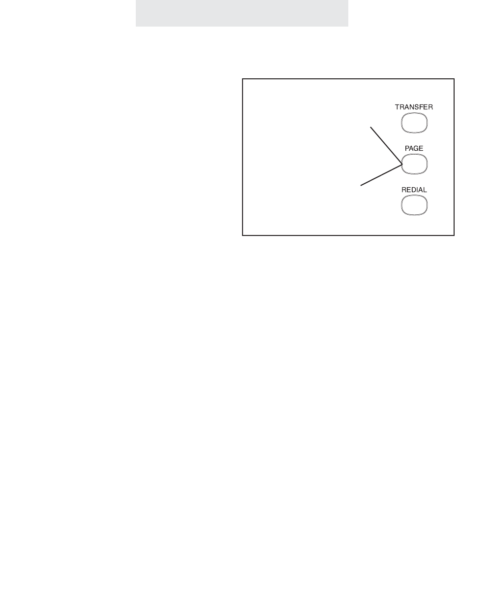
52
Intercom Operation
To page another station:
1Press PAGE.
2 Dial the two-digit station number of
the station you wish to page.
3After you hear the paging tone,
speak towards the telephone or lift
the handset and make your
announcement.
To make an All Page:
1 Press the PAGE button twice.
2After you hear the paging tone,
speak towards the telephone or lift
the handset and make your
announcement.
3 Replace the handset in the cradle or
press the SPEAKER button to hang
up.
Making Pages
The Paging feature allows you to make
announcements to other EPIC stations in the
system. When you make a Page, your speaker-
phone is automatically activated; you can talk
immediately using the speakerphone, or lift the
handset and talk.
Note: You may Page another station only if it is
not in use, does not have DO NOT DISTURB
activated, and is not set to Block Pages. If the
station is in any of these conditions, you will hear
a no action tone.
The All Page feature enables you to make
announcements through all of the other EPIC
stations.
When you make an All Page, your announce-
ment, preceded by a double paging alert tone,
will be heard at all the phones that are not in use
and do not have their DO NOT DISTURB or
Page Block activated.
Press PAGE followed
by a station button to
make a page to that
station
Press PAGE twice
to make an
All Page
ET4000 UG for PDF v8 062502.qxd 6/25/02 12:52 PM Page 62

Intercom Operation
53
To answer a page directed to
your station or an All Page:
1 Lift the handset or press the
SPEAKER or HEADSET button, or
press the flashing INTERCOM but-
ton.
2 Replace the handset in the cradle or
press the SPEAKER or HEADSET
button to hang up.
Answering Pages
Blocking Pages at your telephone:
If you wish, you may block pages at your telephone. If you do so, when a person at another sta-
tion makes an All Page, it will not be heard through your telephone. Also, when anyone tries to
page your station, they will hear a no action tone and will not be able to make their announcement
through your speaker.
To block pages at your telephone, press PROGRAM, then press the soft key under NEXT repeat-
edly until “Intercom Prefs” appears int he display, and then press ENTER. Press the soft key
under NEXT until “Pages” appears in the display, along with the current setting. Press the soft key
under CHANGE if you wish to change the setting. The choices are Pages: ALLOWED (factory
setting), and Pages: BLOCKED. Press PROGRAM to exit.
Once you hear the announcement, you may
answer a page directed to your station by lifting
the handset, pressing the SPEAKER button or
pressing the flashing INTERCOM button. You
may answer an All Page by pressing the flashing
INTERCOM button. In either case you will then
be connected to the caller in a private intercom
conversation.
A page directed to a particular station may be
answered only at that station. However, you
may answer an All Page from any phone in the
system, even one that is busy on an outside line,
has DO NOT DISTURB set or has blocked
pages.
ET4000 UG for PDF v8 062502.qxd 6/25/02 12:52 PM Page 63

54
To choose how your phone
will respond to intercom calls:
1 Press PROGRAM.
- The display will read “Program...”
2 Press the soft key under NEXT
repeatedly, until “Intercom Prefs”
appears in the display, and then
press ENTER.
The display will show the current
intercom setting.
3 Press the soft key under CHANGE
repeatedly, until the desired inter-
com setting is displayed.
The choices are:
Intcm:HANDSFREE (factory setting)
Intcm:RING
Intcm:VOICE
4 Press PROGRAM to exit.
Selecting Intercom Ring, Intercom Voice, or Handsfree
Intercom Operation
You may set your telephone to respond to inter-
com calls in one of three ways:
INTERCOM HANDSFREE: When someone
makes an intercom call to you, your telephone
will ring once, then give you a triple alert tone
which lets you know that your phone has auto-
matically answered the intercom call on speak-
erphone. You may respond to the call simply by
speaking towards your telephone.
INTERCOM RING: When someone makes an
intercom call to you, your telephone will ring
repeatedly with the intercom ring. You may
respond to the call by lifting the handset or
pressing the SPEAKER button.
INTERCOM VOICE: When someone makes an
intercom call to you, your telephone will ring
once, then give you an alert tone, followed by the
caller’s voice. You may respond to the call by
lifting the handset or pressing the SPEAKER
button.
Note: When someone makes an intercom call to
you while you are on an outside line, you will
hear a single intercom ring regardless of your
intercom ringer setting. (See Using Off Hook
Voice Announce, page 55.)
ET4000 UG for PDF v8 062502.qxd 6/25/02 12:52 PM Page 64

To make an off hook voice
announcement:
1Make an intercom call to another
ext. that is busy on an outside call.
2After you hear the confirming tone,
you may make your announcement
and your voice will be heard through
the speaker at the called station.
To respond to an off hook
voice announcement:
1Press the flashing INTERCOM but-
ton. The outside call is automatical-
ly placed on hold.
2Press the LINE button of your out-
side call at any time to return to that
call.
Intercom Operation
55
Using Off Hook Voice Announce
Your EPIC telephone will allow you to make an
intercom call to another station, even if that sta-
tion is busy on an outside call. Your voice will be
heard through the speaker of the called station
without interrupting their call in progress.
Note: If the station you are calling is busy on the
speakerphone or has blocked Off Hook Voice
Announcements, you will still be able to alert the
station with a single ring, but you will not be able
to make your voice announcement.
You may respond to an Off Hook Voice
Announcement by pressing the flashing INTER-
COM button. You will be connected to the other
station on the intercom, and the outside call will
automatically be placed on hold. When you wish
to return to the outside call, press its LINE but-
ton, and the intercom call will be disconnected.
Blocking off hook voice announcements at your telephone:
If you wish, you may block Off Hook Voice Announcements at your telephone.
To do so, press PROGRAM, then press the soft key under NEXT repeatedly until “Intercom Prefs”
appears in the display, and then press ENTER. Press the soft key under NEXT until “OHVA”
appears in the display, along with the current setting. Press the soft key under CHANGE if you
wish to change the setting. The choices are OHVA: ALLOWED (factory setting), and OHVA:
BLOCKED. Press PROGRAM to exit.
ET4000 UG for PDF v8 062502.qxd 6/25/02 12:52 PM Page 65
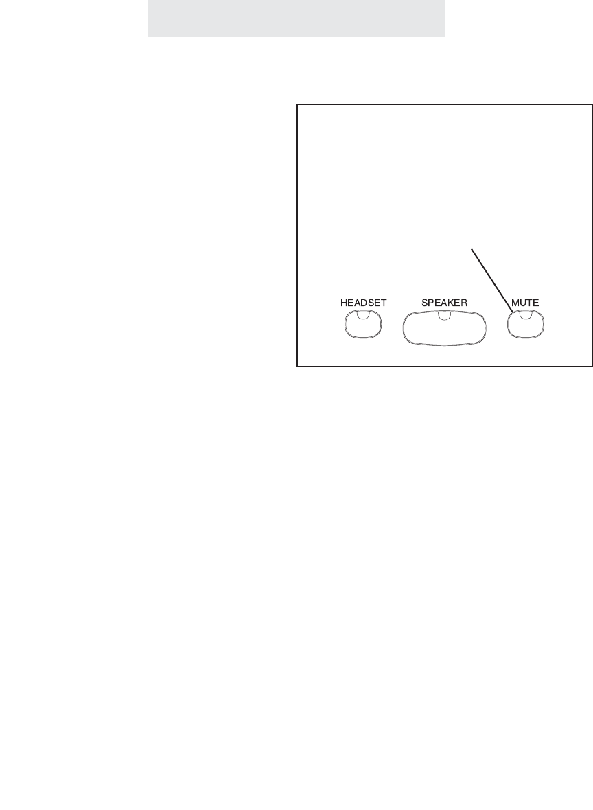
Intercom Operation
56
To monitor a room through the
speakerphone of another sta-
tion:
1 Place an intercom call to telephone
you wish to monitor.
2 Press MUTE if you want to prevent
sounds in your room from being
heard at the monitored phone.
3 To end monitoring, hang up the
handset or press SPEAKER. The
remote station will disconnect imme-
diately.
Note: The remote phone must be
set to Intercom HANDSFREE. (See
page 54.)
The Room Monitoring feature allows you to acti-
vate the speakerphone of another station to
monitor sounds in that room. This feature is
especially useful in a nursery room or home
office where there are children present.
The remote station must be set to INTERCOM
HANDSFREE. When you call this phone on the
intercom, its speakerphone activates and
remains on, allowing you to hear sounds in that
room until you hang up.
To prevent sounds in your room from being
transmitted to the room you are monitoring, you
must press MUTE on your phone.
Monitoring a Room Using the Intercom
Press MUTE at your telephone to prevent
sounds in your room from being transmitted
to the room you are monitoring
To monitor sounds in another room,
place an intercom call to a station that
has been set to HANDSFREE
ET4000 UG for PDF v8 062502.qxd 6/25/02 12:52 PM Page 66

Intercom Operation
Naming Stations
To Name a Station in Your
Epic System:
At Station #11:
1 Press PROGRAM.
- The display will read “Program...”
2Press the soft key under NEXT
repeatedly, until “Station Naming”
appears in the display, and then
press ENTER.
- The display will show the currently
stored name for station #11, or
indicate “No Name” if no name has
yet been given to station #11.
3Press the soft key under CHANGE if
you wish to store a new name for
station #11, or press NEXT repeat-
edly until you see the station num-
ber that you want to name, and then
press CHANGE.
4 Use the dialpad numbers to enter
the name for the desired station.
5 Press the soft key under SAVE.
Repeat steps 1-5 for any additional sta-
tions you wish to name. 1
2
3
4
5
6
7
8
9
,
A
D
G
J
M
P
T
W
-
B
E
H
K
N
Q
U
X
‘
C
F
I
L
O
R
V
Y
&
a
d
g
j
m
S
t
Z
.
b
e
h
k
n
p
u
w
(
c
f
i
l
o
q
v
x
)
2
3
4
5
6
r
8
y
1
s
z
7
9
Guide for Entering Names
If you wish, you may give a name to each of your
Epic telephones, so that people can see the
names along with the station numbers when they
place intercom calls. For example, you might
name station #12 “Mary” and station #15
“Conference Room.”
The table below shows which dialpad numbers
to press for all the different letters and special
characters. Note that you can press the 0, *, and
# buttons if you want those characters, and you
can press the right arrow button below the dis-
play to leave an empty space, and the DELETE
button any time to make corrections.
ET4000 UG for PDF v8 062502.qxd 6/25/02 12:52 PM Page 67

Expanding the Epic System
58
Station
Number
Stn. 11
Stn. 12
Stn. 13
Stn. 14
Line 1
Shared
Shared
Shared
Shared
Line 2
Shared
Shared
Shared
Shared
Line 3
Shared
Shared
Shared
Shared
Line 4
Shared
Shared
Shared
Shared
User’s
Name
Michael
Helen
Sarah
Adam
Station
Number
Stn. 11
Stn. 12
Stn. 13
Line 1
Shared
Shared
Shared
Line 2
Shared
Shared
Shared
Line 3
Shared
Shared
Shared
Line 4User’s
Name
Michael
Helen
Sarah
Private Lines
You may connect private lines to Lines 2, 3 or 4 at each station. A private line is a telephone num-
ber that is connected to just one station. You can have up to three private lines at each telephone.
The Chart below shows a few phones, with each one having its own private Line 4. This is a com-
mon configuration in Centrex environments.
Your Epic system can accomodate up to 16 stations. The maximum number of lines will depend
on how you choose to install the system.
Standard Configuration
This is the most common setup, and is the desired setup for most installations. This installation
is also called “square” in telephone terminology. This means that each telephone in the system is
connected to the same Line 1 telephone number, the same Line 2 telephone number, and so on
for Lines 3 and 4.
The chart below shows a simple square configuration. Note that since all lines are shared by all
the telephones, calls on any line can be transferred to any station. Also, calls put on hold at one
station can be taken off of hold at any other station.
Private
(555-2380)
Private
(555-7516)
Private
(555-7783)
Tel #555-1883 Tel #555-2870 Tel #555-3847 Tel #555-8698
Tel #555-1883 Tel #555-2870 Tel #555-3847 Tel #555-8698
ET4000 UG for PDF v8 062502.qxd 6/25/02 12:52 PM Page 68

Expanding the Epic System
59
IMPORTANT NOTE
If you plan to connect any private or auxiliary lines to your system, please refer to the worksheet
on page 3, and use it as a guide as you connect the telephone lines to your Epic telephones.
Then you must set each line at each station, so the system can know how the lines are con-
nected, and function properly. To do this, go to each station, and follow the instructions found
on page 19.
Auxiliary Lines
You may connect auxiliary lines to Lines 2, 3 or 4 at each station. An auxiliary line is a telephone
number that is shared by two or more stations, but which is a different telephone number than the
corresponding line at the other stations. You can have up to one auxiliary Line 2, one auxiliary Line
3, and up to two auxiliary Line 4’s.
The Chart below shows an installation where a group of stations shares an auxiliary Line 3. This
configuration is useful for workgroups within a company, such as a sales department. Note that in
this example, calls coming in on Lines 1, 2, and 4 could be transferred to any station, but calls
coming in on Line 3 could only be transferred or taken off of hold by stations within their own
group. If this company would like to be able to transfer calls on the L3 AUX telephone number to
a station with the Shared Line 3 telephone number, they would need to subscribe to a service such
as Centrex from their local telephone company.
Station
Number
Stn. 11
Stn. 12
Stn. 13
Stn. 14
Stn. 15
Stn. 16
Line 1
Shared
Shared
Shared
Shared
Shared
Shared
Line 2
Shared
Shared
Shared
Shared
Shared
Shared
Line 3 Line 4
Shared
Shared
Shared
Shared
Shared
Shared
User’s
Name
Michael
Helen
Sarah
Adam
Kate
Lunch Room
L3 AUX 1
(555-6381)
L3 AUX 1
(555-6381)
L3 AUX 1
(555-6381)
Shared
Shared
Shared
Tel #555-1883 Tel #555-2870 Tel #555-3847 Tel #555-8698
ET4000 UG for PDF v8 062502.qxd 6/25/02 12:52 PM Page 69

Using Centrex With Your EPIC Telephone
Centrex Operation
To set up a private Centrex line
at your telephone:
1 Connect the desired private Centrex
line to your telephone.
2 Follow the instructions on page 19
for setting up private lines.
To assign a distinctive ring to
your Centrex line:
1 Follow the instructions for assigning
distinctive rings, which are found on
page 13.
To store a Centrex code into a
memory location:
1 Follow the instructions starting on
page 45 for storing numbers into
memory dial locations.
To pick up another station’s
ringing line:
1 Dial the Centrex pickup code, or
press the memory button where you
have stored the Centrex pickup code.
2 Dial the Centrex phone number of
the ringing station.
Your EPIC telephone is ideal for use in a Centrex
environment.
You can easily connect a private Centrex tele-
phone number to Line 2, 3 or 4 at your phone.
The only telephone line that must be connected
to the same telephone number on all phones in
the system is Line 1.
If you wish, you may assign your Centrex line its
own distinctive ringing tone, so that you can eas-
ily differentiate calls ringing on your Centrex line
from calls ringing on the other lines, or on other
nearby phones.
You may store your Centrex codes into memory
locations and access them at the touch of a but-
ton. This is much more convenient than dialing
the appropriate Centrex feature code every time
you wish to use a Centrex feature.
You can pick up another station’s ringing line
from any other telephone.
If you have set your phone as a Centrex console,
and you are being alerted by another station that
its Centrex line is ringing, you may pick up that
line by dialing the Centrex pickup code, followed
by the Centrex telephone number of the station
sending the ring.
60
ET4000 UG for PDF v8 062502.qxd 6/25/02 12:52 PM Page 70

Centrex Operation
Storing the Centrex Prefix
To store the Centrex prefix:
1 Press PROGRAM.
- The display will read “Program...”
2 Press the soft key under NEXT
repeatedly, until “Centrex Prefix”
appears in the display, then press
ENTER.
The display will show the currently
stored Centrex prefix, or indicate
“XXXXXXX” if none has been
stored.
3 Press the soft key under CHANGE,
then enter the desired Centrex pre-
fix, up to seven digits.
4 Press the soft key under SAVE.
5 Press PROGRAM to exit.
If you wish, you may store the Centrex prefix at
your telephone.
The Centrex prefix is the part of the telephone
that you DO NOT dial when you wish to reach
another Centrex number in your system. For
example, if your Centrex telephone number is
609-555-1380, and people in your office can
reach you by dialing “1380”, then your Centrex
prefix is “609555.”
Entering your Centrex prefix is useful if you sub-
scribe to Caller ID service, and would like the
convenience of dialing other Centrex stations
from your caller list. When you dial a number
from the caller list, the telephone will dial it as it
is shown in the display. If you have entered the
Centrex prefix, the number will be displayed
properly, so that you can dial it simply by press-
ing DIAL or going off-hook.
61
ET4000 UG for PDF v8 062502.qxd 6/25/02 12:52 PM Page 71

Centrex Operation
Setting up a Telephone as a Centrex Console
62
To set up a telephone as a
Centrex console:
1 Press PROGRAM.
- The display will read “Program...”
2 Press the soft key under NEXT
repeatedly, until “Centrex Console”
appears in the display, and then
press ENTER.
The display will show the current
console setting.
3 Press the soft key under CHANGE
until the desired console setting is
displayed.
The choices are:
Centrex CSL: OFF (factory setting)
Centrex CSL: ON
4 If you have chosen to set the con-
sole ON, then press the soft key
under NEXT repeatedly and the
softkey under CHANGE whenever
you wish, to choose which of the
stations you wish this telephone to
act as a console for.
Note that you may set up multiple
Centrex consoles, and have each of
them be alerted only when the
Centrex lines of particular stations
are ringing
5 Press PROGRAM to exit.
You may choose to set one or more of your Epic
telephones as a Centrex console. Any phone
that you set as a Centrex console will be alerted
by a short ring when another station’s Centrex
line is ringing, and the display will indicate which
phone is ringing by flashing the corresponding
station indicator.
When you set up a Centrex console, you can
decide which stations you wish to act as a con-
sole for. A secretary, for instance, may only wish
to act as a Centrex console for the phone of his
or her boss.
The Centrex console will be alerted that the
other phone is ringing after a certain delay, which
is set at that other phone. Once you get this
alert, you may answer that other station’s ringing
line by dialing the Centrex pickup code, followed
by the Centrex telephone number of the line you
want to pick up.
Note that if the other station’s ring console set-
ting is set to “NO,” the Centrex console will get
no alert.
ET4000 UG for PDF v8 062502.qxd 6/25/02 12:52 PM Page 72

Centrex Operation
Setting a Telephone to Ring a Centrex Console
63
To set up a telephone to ring a
Centrex console:
1 Press PROGRAM.
- The display will read “Program...”
2 Press the soft key under NEXT
repeatedly, until “Ring Console”
appears in the display, and then
press ENTER.
The display will show the current
ring console setting.
3 Press the softkey under CHANGE
until the desired ring console setting
is displayed.
The choices are:
Ring Console: NO (factory setting)
Ring Console: YES
4 If you have chosen “YES,” then you
must decide how many seconds you
want this station to delay before
ringing the Centrex console. Press
CHANGE repeatedly to choose a
delay of between 2 and 30 seconds.
Note that one ring cycle is approxi-
mately 6 seconds.
Then you must press the soft key
under CHANGE until the desired
Centrex Line is displayed.
The choices are:
Centrex Line: L2
Centrex Line: L3
Centrex Line: L4 (factory setting)
5 Press PROGRAM to exit.
If you wish your telephone to notify any Centrex
consoles that may have been set up that your
Centrex line is ringing, you must choose how
long you want your phone to delay before alert-
ing the Centrex console.
Note that if you wish your telephone to alert a
Centrex Console, you must set your ring con-
sole setting to “YES.”
Then you must decide how many seconds you
want your station to delay before alerting the
Centrex Console. You may choose a delay
between 2 and 30 seconds.
In addition, you must specify which one of your
lines is your private Centrex line. This is impor-
tant, because only when this line rings will the
Centrex console be alerted. Calls ringing on the
other lines will have no effect on the console.
Note that once you set up your telephone to
ring a Centrex console, you are simply broad-
casting an alert whenever your Centrex line is
ringing. The alerts that you broadcast will be
received by any other station that has been set
up as a Centrex console for your station.
ET4000 UG for PDF v8 062502.qxd 6/25/02 12:52 PM Page 73

Using Other Telephones With Your EPIC Telephone
Additional Information
Using other EPIC intercom telephones
Your EPIC telephone is fully compatible with other EPIC intercom phones from TMC. You may
mix and match basic, voice mail, and cordless versions as well as mixing and matching EPIC tele-
phones with different numbers of lines. The EPIC system boasts flexibility as well as expandabil-
ity.
Using standard telephones
You may also use standard (non-EPIC) telephones in conjunction with your EPIC telephones. All
features of the non-EPIC telephones will operate normally. However, they will not be able to share
the features of the EPIC telephones.
Line Status and Calls on Hold
The line status indicators of the EPIC phones will recognize the standard telephones, and when
you place a call on hold at a EPIC telephone, you will be able to take the call off hold at a stan-
dard telephone.
Note: If the line status indicators of your EPIC telephones do not function properly, either failing
to light up when a standard telephone uses a line, or staying lit even though no telephone is using
a line, then please see page 73 and follow the instructions for setting the loop voltage detector.
Call Privacy
Call privacy is not observed by non-EPIC telephones. A non-EPIC telephone on any line has
access to that line at any time, whether or not it is being used by a EPIC telephone.
Intercom
Non-EPIC telephones cannot use the intercom feature to communicate with EPIC telephones.
Using fax machines and computer modems
You may connect computer modems or fax machines to any of your lines, and the line indicators
of the Epic telephones will light when these devices are using a line.
You may also connect fax machines and computer modems to Line 2 by connecting them to the
data/fax jacks. Use of the data/fax jack is discussed on the following page.
64
ET4000 UG for PDF v8 062502.qxd 6/25/02 12:52 PM Page 74
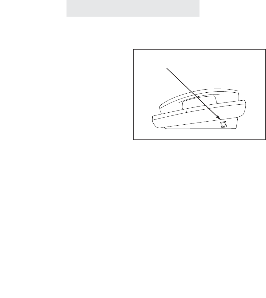
Using the Data/Fax Jack
Additional Information
65
To connect a modem or a fax
machine to your Epic phone:
1 Simply plug your modem or fax
machine into the data/fax jack on
the side of the telephone.
For added convenience, you may connect
modems or fax machines to the telephone line
by plugging them into the data/fax jacks, which
are found on the right side of the Epic tele-
phones.
Note that the data/fax jack is connected to Line
2.
The data/fax jack is found on the
right side of your Epic phone
ET4000 UG for PDF v8 062502.qxd 6/25/02 12:52 PM Page 75

External Feature Module set
as a Music On Hold Adapter
1Install External Feature Module.
2Follow the instructions to set it as a
Music on Hold Adapter.
3Connect a radio or continuous loop
recording to the Adapter.
External Feature Module set
as an External Paging Adapter
1Install External Feature Module.
2Follow the instructions to set it as a
External Paging Adapter.
3Connect an amplifier and speaker to
the Adapter.
Additional Information
The Music on Hold Adapter enables you to eas-
ily provide music or a recorded message to
callers on hold.
The External Paging Adapter allows you to con-
nect an amplifier and speaker to your EPIC sys-
tem. This accessory is perfect for making
announcements in warehouses, outdoor loca-
tions or throughout an entire office.
Using Optional External Feature Module
66
ET4000 UG for PDF v8 062502.qxd 6/25/02 12:52 PM Page 76

Additional Information
You may connect up to four Door Intercom
Adapters to your EPIC system. Connect each
one to a separate door intercom speaker and
assign each a different station number from 23 to
26 (Follow the instructions supplied with the
adapter).
When someone rings a door speaker, its corre-
sponding station indicator will flash at all the
phones. You may answer the door, via the inter-
com, from any station by placing an intercom call
to that station.
You may set the door intercom bell volume at
each phone separately. The lowest volume set-
ting at each telephone is “OFF”, so you can eas-
ily turn off the doorbell at particular telephones.
If you choose to connect a magnetic door strike
to the system, you may unlock this door from any
station by pressing the memory button which has
been made into a “key” for this door.
To make a memory button into a “key”, press
PROGRAM, then MEM, then the memory button
where you wish to store the door “key”. Press
CHANGE, then press FLASH, then HOLD, fol-
lowed by the number of the desired door box
(from “23” to “26”), then press SAVE.
Note: You may press the memory button to
unlock the door at any time. There is no need
to be connected to the door speaker over the
intercom.
External Feature Module set as a
Door Intercom/Door Opener Adapter
1Install External Feature Module.
2Follow the instructions to set it as a
Door Intercom Adapter.
3Connect a door intercom speaker to
the Adapter.
4If you wish, you may connect a mag-
netic door strike to the Adapter.
To answer a door speaker over the
intercom:
1Place an intercom call to the number
that is flashing in your display.
To adjust the door intercom bell
volume at your telephone:
While the phone is on-hook and idle:
1Press HOLD.
2Press PAGE.
3Press the up and down VOLUME
buttons to set desired door intercom
bell volume.
To unlock a magnetic door lock:
1Press the memory button that has
been made into a “key” for this door.
Using Optional External Feature Module (Continued)
67
ET4000 UG for PDF v8 062502.qxd 6/25/02 12:52 PM Page 77
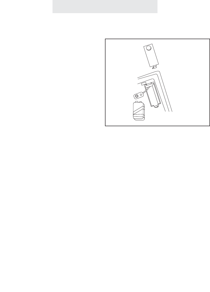
1Make sure the AC cord remains
attached to the telephone and to an
electrical outlet.
2 Turn the telephone over.
3Remove desk pedestal/wall mount
bracket if attached.
4Remove battery door cover by using
the tip of a ball-point pen, or paper
clip, or similar object to release the
battery door tab.
5Remove the old battery.
6Insert a new 9-volt battery.
7Close the battery cover.
Additional Information
Replacing Your Battery
Operation During a Power Failure
Your EPIC telephone uses AC power from a
standard wall outlet. As long as the tele-
phone is connected to a wall outlet, it will
operate using the AC power. Please remem-
ber to plug your telephone into a wall out-
let that is not controlled by a wall switch.
If AC power is disconnected or there is a
power failure, the telephone automatically
switches to battery operation for approxi-
mately two hours. When the power is
restored, the telephone automatically switch-
es back to AC power and resumes normal
operation. If the battery is missing or low on
power when AC power is lost, the telephone
will not function. However, all feature settings
and memory numbers will be maintained,
since they are stored in a static memory that
retains its contents without electricity.
Please note that it is not necessary for you to
install a battery in your Epic telephone for it to
function normally. In fact, a battery is not even
needed to preserve your memory dial numbers
in the event of a power failure. This is because
all memory dial numbers are stored in a static
memory which retains its contents even with no
electrical power. The only purpose of having a
battery installed is so that the telephone itself
can function for up to two hours in the event of a
power failure. You may wish to install a battery
in at least one Epic phone for emergency opera-
tion, or have another standard phone available.
If you do choose to install a battery in your Epic
telephone, we recommend only the use of an
alkaline battery. Also, please make sure to
install the battery after the telephone has
already been plugged into the AC electrical out-
let.
Note: It is recommended that you have at
least one standard telephone connected, that
does not require battery power, so that you
are always sure to have use of a telephone
during a power failure.
ET4000 UG for PDF v8 062502.qxd 6/25/02 12:52 PM Page 78

Adjusting Held Call Reminder
Additional Information
1 Press PROGRAM.
- The display will read “Program...”
2 Press the soft key under NEXT
repeatedly, until “Hold Remind”
appears in the display. The display
will show the currently set held call
reminder time.
3Press the soft key under CHANGE
repeatedly, until the desired held call
reminder time is displayed.
The choices are:
Hold Remind:2min (factory setting)
Hold Remind:1min
Hold Remind:30s
Hold Remind:OFF
4Press PROGRAM to exit.
Your EPIC telephone is factory-set to automati-
cally alert you at 2 minutes, and then every 2
minutes thereafter, if a caller is still on hold. This
feature is designed to prevent calls from acci-
dentally being left on hold for long periods. If you
would prefer a different first reminder time, you
may change the setting to 30 seconds or 1
minute, or you may set the Held Call Reminder
OFF if you prefer.
69
ET4000 UG for PDF v8 062502.qxd 6/25/02 12:52 PM Page 79

Adjusting Auto Hold Drop Time
Additional Information
1 Press PROGRAM.
- The display will read “Program...”
2Press the soft key under NEXT
repeatedly, until ”Advanced Setting”
appears in the display, and then
press ENTER.
3 Press the soft key under NEXT
repeatedly, until “Hold Drop Time”
appears in the display, and then
press ENTER.
The display will show the currently
set hold drop time.
4Press the soft key under CHANGE
repeatedly, until the desired hold
drop time is displayed.
The choices are:
Hold Drop: 5 MIN (5 Minutes)
Hold Drop:15 MIN
Hold Drop:30 MIN (factory setting)
5Press PROGRAM to exit.
Your EPIC telephone is factory-set to automati-
cally drop a call if it is on hold for more than 30
minutes. This feature is designed to prevent
calls from accidentally being placed on hold
indefinitely. If you would prefer a different length
of time, you may change the setting 5 minutes or
15 minutes instead.
70
ET4000 UG for PDF v8 062502.qxd 6/25/02 12:52 PM Page 80

Adjusting Flash Length
Additional Information
71
Your EPIC telephone is factory-set to have a
flash length of 700 milliseconds, which is appro-
priate for most environments. However, if your
installation requires a longer or shorter flash
length, you may change the length to 100 mil-
liseconds, 300 milliseconds, or 1 second.
1 Press PROGRAM.
- The display will read “Program...”
2Press the soft key under NEXT
repeatedly, until “Advanced Setting”
appears in the display, and then press
ENTER.
3Press the soft key under NEXT
repeatedly, until “Flash Length”
appears in the display, and then press
ENTER.
The display will show the currently set
flash length.
4Press the soft key under CHANGE
repeatedly, until the desired flash
length is displayed.
The choices are:
Length:100ms (100 milliseconds)
Length:300ms
Length:700ms (factory setting)
Length:1 second
5Press PROGRAM to exit.
ET4000 UG for PDF v8 062502.qxd 6/25/02 12:52 PM Page 81

72
To erase all the feature settings stored at a par-
ticular station and return that telephone to its
original factory settings, follow these steps.
Note that when you erase all feature settings at
a particular station, you do not erase the memo-
ry dial or the shared directory dial numbers that
may be stored in this station. If you ever wish to
erase stored memory numbers, follow the
instructions on page 49.
Erasing All Feature Settings
To erase all feature settings at
a particular telephone:
1 Press PROGRAM.
- The display will read “Program...”
2Press the soft key under NEXT
repeatedly, until “Advanced Setting”
appears in the display, and then
press ENTER.
3 Press the soft key under NEXT until
“Erase Settings” appears in the dis-
play, and then press ENTER.
- The display will read “Feature
Settings.”
4 Press the soft key under ERASE.
- The display will read “Erasing
Done!”
Additional Information
ET4000 UG for PDF v8 062502.qxd 6/25/02 12:52 PM Page 82

Setting the Loop Voltage Detector
To set your telephone’s loop
voltage detector:
1 Press PROGRAM.
- The display will read “Program...”
2Press the soft key under NEXT
repeatedly, until “Advanced Setting”
appears in the display, and then
press ENTER.
3Press the soft key under NEXT
repeatedly, until “Loop Detect”
appears in the display, along with
the current setting.
4Press the soft key under CHANGE
repeatedly, until the desired loop
detect setting is displayed.
The choices are:
Loop Detect: 48V (factory setting)
Loop Detect: 24V (24 volts)
Loop Detect: 12V
Loop Detect: OFF
5Press PROGRAM to exit.
Additional Information
Your Epic telephone will light up its line status
indicators when a non-EPIC telephone such as a
fax machine, modem, or standard telephone is
using a line.
Note: If the line status indicators of your EPIC
telephones do not function properly, either failing
to light up when a standard telephone uses a
line, or staying lit even though no telephone is
using a line, then the loop voltage detector set-
ting needs to be adjusted.
The factory setting of 48 volts is appropriate for
most installations. If this is not suitable, try set-
ting your phone to 24 volts, and if that does not
work, then set it to 12 volts. You can also turn
this feature OFF if you prefer.
If a line indicator at your EPIC telephone stays lit
because there is no telephone line connected,
and you wish to turn it off, do not use this feature.
Instead refer to page 19 and set this unconnect-
ed line at this station to UNCONNECTED.
73
ET4000 UG for PDF v8 062502.qxd 6/25/02 12:52 PM Page 83

Additional Information
Troubleshooting Guide
74
If you are having difficulty with your EPIC telephone, DO NOT RETURN IT!
You may find your problem and solution listed below. If not, call TMC’s toll-free customer support
line at 1-800-TMC-1638, and an expert will walk you through your problem. You may also use this
toll-free line if you ever have a question that is not answered in your User’s Guide.
The telephone does not work,
and you do not get dial tone.
The display reads “Station
#??”
The intercom does not work
OR
The telephone does not indi-
cate the status of the other
EPIC phones in the system
OR
There is a delay in getting dial
tone.
Check all connections and make sure that they are secure-
ly in place (See pages 4-7).
Make sure that the AC adapter is plugged into a jack not
controlled by a wall switch.
If possible, check your jack wiring by testing a non-system
phone at the jack in question. If this standard telephone
does not work, then local telephone company lines or your
own wiring may be causing the problem.
Press the soft key under CHANGE to assign this telephone
a station number (See page 8).
The problem may be with your installation:
Make sure that the telephone lines are properly installed
(See page 9).
The problem may be with one telephone:
Disconnect one telephone at a time to determine if a partic-
ular phone is causing the problem.
The problem may be caused by interference:
Disconnect all possible sources of interference one at a time
to determine if one of these is causing the problem.
Possible sources are such things as other phones, fax
machines, modems, or such things as radios or computers
in extremely close proximity.
The problem could be caused by outside interference:
Disconnect Line 1 from dial tone at the network interface. If
this solves the problem, then the interference is coming from
outside over Line 1. If this is the case, call TMC to request
an RF line filter, which will be sent to you free of charge.
ET4000 UG for PDF v8 062502.qxd 6/25/02 12:52 PM Page 84

Solution
Problem
Additional Information
Troubleshooting Guide (Continued)
75
The line LED flashes when a
call comes in, but the tele-
phone does not ring.
Some telephones do not ring.
The telephone does not oper-
ate during a power outage.
The battery icon stays lit in the
display.
You cannot hear the other
party.
You cannot join a telephone
call in progress.
The telephone line status indi-
cators stay lit, even though the
line is not in use.
Other problems.
Make sure that the ringer is on (See page 22).
Adjust the ringer volume control (See page 23).
Make sure that Do Not Disturb is not on (See page 37).
If there are several non-system telephones on the line that
does not ring disconnect some of them.
Make sure that a fresh 9-volt battery is installed in the tele-
phone (See page 68).
Make sure that a fresh 9-volt battery is installed in the tele-
phone (See page 68).
Adjust the volume control (See page 23).
The Call Privacy feature prevents another EPIC telephone
from interrupting a call in progress. The person already on
the call may release the call privacy or conference you into
the call (See pages 29 and 39).
If you don’t want Call Privacy in your system, you can turn it
off (See page 18).
If this line is not connected to a telephone line, you must set
it as UNCONNECTED (See page 19).
If this line is connected to a telephone line, yet still stays lit,
then adjust the loop voltage detector setting (See page 73).
Make sure that you have followed all of the instructions in
this User’s Guide. If you continue to have problems, call
TMC’s toll-free customer support line at 1-800-TMC-1638. If
you cannot correct the problem, disconnect the telephone
and refer to the TMC limited warranty information on page
78.
ET4000 UG for PDF v8 062502.qxd 6/25/02 12:52 PM Page 85

Additional Information
This equipment complies with Part 68 of the FCC rules. On the base of this equipment is a label
that contains, among other information, the FCC registration number and ringer equivalence num-
ber (REN) for this equipment. If requested, this information must be provided to the telephone
company.
The FCC requires that you connect your telephone to the telephone network through a modular
telephone outlet or jack, which must comply with FCC part 68 rules.The modular telephone outlet
or jack to which your EPIC telephone must be connected is a USOC RJ11C or RJ14C.
The Facility Interface Codes (FIC) for your EPIC telephone is 02LS2 which is a 2-wire, Local
Switched Access, Loop-start.
The REN is used to determine the quantity of devices which may be connected to the telephone
line. The REN for your EPIC telephone is 0.2. Excessive RENs on the telephone line may result
in the devices not ringing in response to an incoming call. In most, but not all areas, the sum of
the RENs should not exceed five (5). To be certain of the number of devices that may be con-
nected to the line, as determined by the total RENs, contact the telephone company to determine
the maximum REN for the calling area.
If the terminal equipment EPIC telephone causes harm to the telephone network, the telephone
company will notify you in advance that temporary discontinuance of service may be required. But
if advance notice isn’t practical, the telephone company will notify you as soon as possible. Also,
you will be advised of your right to file a complaint with the FCC if you believe it is necessary.
The telephone company may make changes in its facilities, equipment, operations or procedures
that could affect the operation of the equipment. If this happens, the telephone company will pro-
vide advance notice in order for you to make the necessary modifications in order to maintain unin-
terrupted service.
If trouble is experienced with your EPIC telephone, please contact TMC Corporation at 1-800-
TMC-1638 for repair and/or warranty information. If the trouble is causing harm to the telephone
network, the telephone company may request you remove the equipment from the network until
the problem is resolved. Do not attempt to repair or modify this equipment. Please contact TMC
Corporation for information on obtaining service for this product.
This equipment cannot be used on public coin service provided by the telephone company.
Connection to Party Line Service is subject to state tariffs. (Contact the state public utility com-
mission, public service commission or corporation commission for information.)
This equipment is hearing-aid compatible.
76
FCC Information
ET4000 UG for PDF v8 062502.qxd 6/25/02 12:52 PM Page 86

This equipment is capable of providing users access to interstate providers of operator services
through the use of access codes. Modification of this equipment by call aggregators to block
access dialing codes is a violation of the Telephone Operator Consumers Act of 1990.
Warning: Changes or modifications to this unit not expressly approved by the party responsible
for compliance could void the user’s authority to operate the equipment.
NOTE: This equipment has been tested and found to comply with the limits for a Class B digital
device, pursuant to Part 15 of the FCC Rules. These limits are designed to provide reasonable
protection against harmful interference in a residential installation. This equipment generates,
uses, and can radiate radio frequency energy and, if not installed and used in accordance with the
instructions, may cause harmful interference to radio communications. However, there is no guar-
antee that interference will not occur in a particular installation. If this equipment does cause
harmful interference to radio or television reception which can be determined by turning the equip-
ment off and on, the user is encouraged to try to correct the interference by one or more of the fol-
lowing measures:
- Reorient or relocate the receiving antenna.
- Increase the separation between the equipment and receiver.
- Connect the equipment into an outlet on a circuit different from that to
which the receiver is connected.
- Consult the dealer or an experienced radio TV technician for help.
This Class B digital apparatus complies with Canadian ICES-003.
Cet appareil numérique de la classe B est conforme à la norme NMB-003 du Canada.
Automatic Dialers
When programming emergency numbers and/or making test calls to emergency numbers:
- Remain on the line and briefly explain to the dispatcher the reason for the
call before hanging up.
- Perform such activities in the off-peak hours, such as early morning hours
or late evenings.
Additional Information
77
FCC Information (Continued)
ET4000 UG for PDF v8 062502.qxd 6/25/02 12:52 PM Page 87

TWO-YEAR LIMITED WARRANTY
We urge you to complete the Warranty Registration Form enclosed with your product and send
it in. This will enable you receive future updates and product information from TMC.
What does your warranty cover?
Any defect in material or workmanship.
For how long after the original purchase?
Two years.
What will TMC do?
We will repair or, at our option, replace your TMC product at no charge to you. If we repair
your product, we may use reconditioned replacement parts. If we choose to replace your prod-
uct, we may replace it with a reconditioned one of the same or of a similar design. The
exchange unit will be warranted for the remainder of your product’s original warranty period.
How do you make a warranty claim?
Call TMC to receive a Return Authorization Number. Properly pack your unit, and write the
Return Authorization Number on the outside of the box. Do not include the cords etc. which
were originally provided with the product unless specifically requested to do so by the TMC
representative. Include in the package a copy of the sales receipt or other proof of the date of
original purchase. Also print your name, address, phone number, and a detailed description of
the defect or operating problem. Ship the product standard UPS or registered mail (you must
prepay all shipping costs) to:
TMC Corporation, Product Service Center, 2540 Route 130, Unit 117, Cranbury, NJ 08512
After repairing or replacing your TMC product, we will ship it back to you at no cost to you.
What does this warranty not cover?
- Customer instruction. Your User’s Guide provides information regarding operating
instructions and user controls. For additional information, ask your dealer.
- Installation and set-up adjustments. Your User’s Guide provides information regarding instal-
lation instructions. Please see your dealer for additional information.
- Batteries, defects resulting from accidents, alterations, unauthorized repair, failure to follow
instructions, misuse, neglect, fire, floods, lightning, and acts of God.
- Product which has been modified or incorporated into other products.
Additional Information
78
Warranty Information
ET4000 UG for PDF v8 062502.qxd 6/25/02 12:52 PM Page 88

79
Additional Information
- Product purchased or serviced outside the U.S.
We do not warrant your TMC products to be compatible with any particular telephone equip-
ment or party line, key telephone systems, or more sophisticated customer premises switching
systems.
Neither do we warrant your TMC products to function properly in all user environments, since
wiring and other factors can affect performance.
Limitations and Exclusions
This warranty is the only one we offer for your TMC product, and it sets forth all our responsi-
bilities regarding your TMC product. There are no other express warranties.
TMC CORPORATION SHALL NOT BE LIABLE FOR INCIDENTAL OR CONSEQUENTIAL
DAMAGES RESULTING FROM THE USE OF THIS PRODUCT, OR ARISING OUT OF ANY
BREACH OF THIS WARRANTY. ALL EXPRESS AND IMPLIED WARRANTIES, INCLUDING
THE WARRANTIES OF MERCHANTABILITY AND FITNESS FOR A PARTICULAR PUR-
POSE, ARE LIMITED TO THE APPLICABLE WARRANTY PERIOD SET FORTH ABOVE.
Some states do not allow the exclusion or limitation of incidental or consequential damages, or
limitations on how long an implied warranty lasts, so the above exclusions or limitations may
not apply to you. This warranty gives you specific legal rights and you may also have other
rights which vary from state to state.
Warranty Information (Continued)
ET4000 UG for PDF v8 062502.qxd 6/25/02 12:52 PM Page 89

Index
80
Access Code, 14
Accessories, iii, 66-67
Automatic Line Selection, 12
Auxiliary Lines, 2-3, 19, 59
Battery Operation, 68
Caller ID, 32-33, 49
Call Privacy, 18, 39
Call Timer, 41
Centrex Console, 62-63
Centrex Operation, 60-63
Clock & Calendar Setting, 43
Conference Calling, 29
Data/Fax Jack, 65
Delete, 25, 32-33
Desk Pedestal, 20
Desk/Table Installation, 4-5
Dial, 32-33, 46-47
Distinctive Ringing, 13
Do Not Disturb, 37
Door Intercom Adapter, iii, 67
Erasing Numbers
- erasing all memory dial numbers, 49
- erasing all shared directory numbers, 49
- erasing toll restrictions, 49
Erasing Settings
- erasing all feature settings, 72
External Feature Module, iii, 66-67
External Paging Adapter, iii, 66
FCC Information, 76-77
Flash, 35, 48
- adjusting flash length, 71
Handsfree Answer on Intercom, 51, 54
Headset Operation, 42
Hold Feature, 27
- adjusting held call reminder, 69
- adjusting auto hold drop time, 70
Indicator Light Description, 21
Intercom
- making intercom calls, 50
- answering intercom calls, 51
- making pages, 52
- making All Pages, 52
- answering pages, 53
- blocking pages at your telephone, 53
- using Off Hook Voice Announce, 55
- monitoring a room, 56
- intercom ring selection, 54
Installation
- identifying existing wiring, 1
- planning your installation, 2-3
- installing desk/table phones, 4-5
- installing wall mounted phones, 6-7
- assigning station numbers, 8
- verifying proper installation, 9
Line Preference, 12
Line Reserve, 38
Line Selection, 12
Location of Controls, vii-viii
Loop Voltage Detection, 73
Making and Answering a Call, 25, 28
- using speakerphone, 25
- using redial, 26, 49
Memory Dialing
- features, 44
- storing numbers & dialing, 45
- personal directory dials, 46
- shared directory dials, 47
- special memory features, 48-49
Music On Hold Adapter, iii, 66
Mute, 36
ET4000 UG for PDF v8 062502.qxd 6/25/02 12:52 PM Page 90

81
Naming Stations, 57
New Call Lamp, 34
Non-System Phones, 64
Off Hook Ringing, 22, 28
Off Hook Voice Announce
- making off hook voice announcement, 55
- responding to an off hook voice
announcement, 55
- blocking off hook voice announcements at
your telephone, 55
Optional Accessories
- music on hold adapter, iii, 66
- external paging adapter, iii, 66
- door intercom adapter, iii, 67
- 25 foot line cord, iii
- 25 foot handset cord, iii
- headset, iii
Packing List, ii
Paging
- paging another station, 52
- paging all phones, 52
- answering pages, 53
- blocking pages, 53
Pause, 48
Power Failure Operation, 68
Predialing, 25, 49
Private Lines, 2-3, 19, 58
Problems and Solutions, 74-75
Redial, 26, 49
Resetting Your Phone, 72
Restricting Your Phone, 14-17
Ring Centrex Console, 63
Ringer Control, 22
Room Monitoring, 56
Safety Information, i
Setting Up Your System, 10-19
- erasing all feature settings, 72
Shared Directory Dials, 44, 47
Speed Dials, 45
Standard Configuration, 2, 58
Station Number Assignment, 8
Station Programming
- at each station, 10
- at station #11, 11
Switching Between Lines, 28
Telephone Company Voice Mail, 34
Time and Date Adjustment, 43
Toll Restriction
- turning on and off, 40
- setting up, 14-17
Toll Restriction Access Code, 14
Tone/Pulse Selection, 24
- temporary tone dialing, 24, 48
Transferring Calls, 30-31
Troubleshooting Guide, 74-75
Unconnected Lines, 2-3, 19
Voice Mail, 34
Volume Level Adjustments, 23
Wall Mounting Bracket, 20
Wall Mounting Instructions, 6-7
Warranty Information, 78-79
Index
ET4000 UG for PDF v8 062502.qxd 6/25/02 12:52 PM Page 91

TMC Corporation
2540 Route 130, Unit 117
Cranbury, NJ 08512
(609) 860-1830
Toll-free 1-800-TMC-1638
Fax (609) 860-8980
©2002 TMC Corporation
Printed in China
LIB702YY
Rev 1.1
ET4000 UG for PDF v8 062502.qxd 6/25/02 12:52 PM Page 92
