Tokyo Hy Power Labs HL-25KFX High Power Amplifier User Manual users manual
Tokyo Hy-Power Labs, Inc. High Power Amplifier users manual
UserManual.wiki
>
Tokyo Hy Power Labs
>
HL 25KFX User Manual
users manual
Navigation menu
Upload a User Manual
Namespaces
Wiki Guide
HTML
PDF
Info
Views
User Manual
Discussion / Help
Navigation
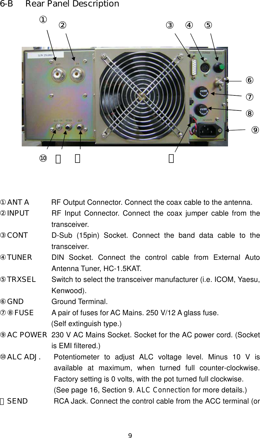
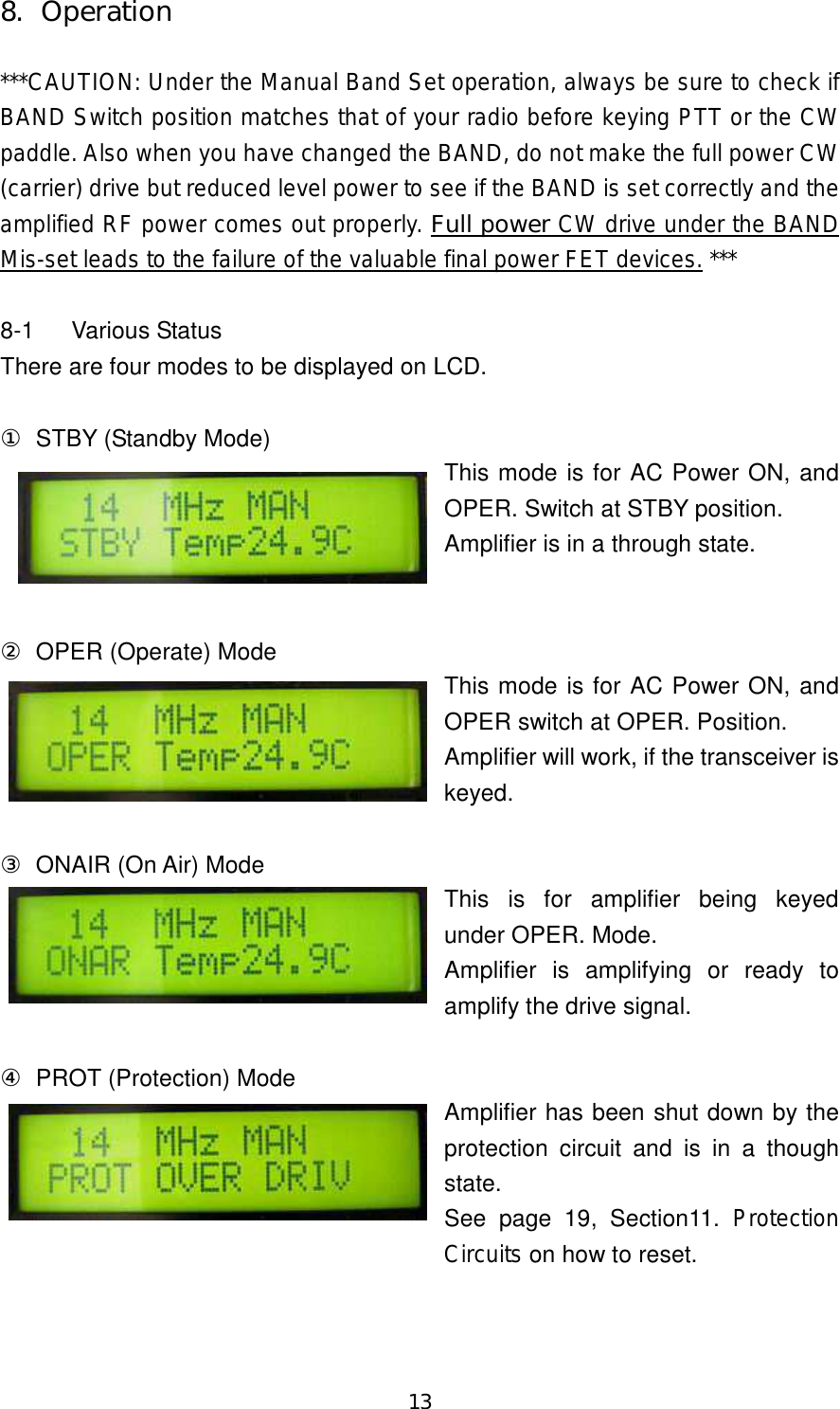
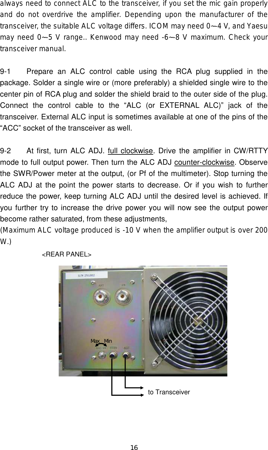
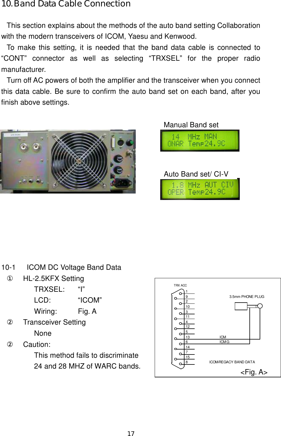
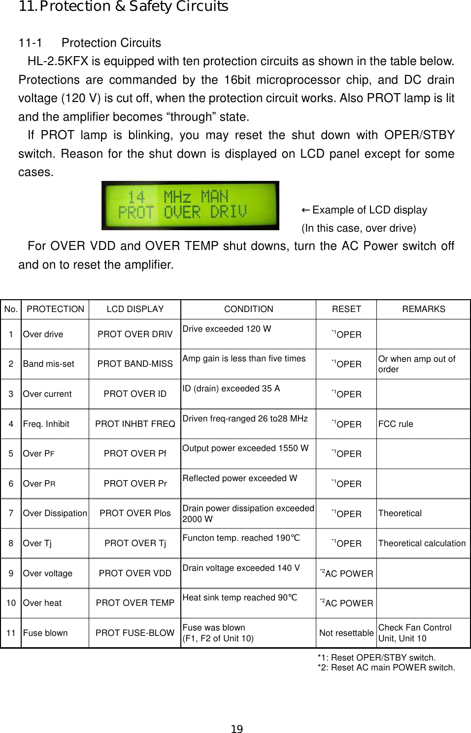
![18 10-2 ICOM CI-V ① HL-2.5KFX Setting TRXSEL: “C” LCD: “CIV” Wiring: Fig. B ② Transceiver Setting CI-V BAUD RATE: 9600 [bps] CI-V ADDRESS: 5 Ch CI-V Transceiver: ON CI-V with IC-731: OFF (See ICOM radio manual for the details.) 10-3 Yaesu Band Data ① HL-2.5KFX Setting TRXSEL: “Y” LCD: “YSU” Wiring: Fig. C ② Transceiver Setting None 10-4 Kenwood RS-232C ① HL-2.5KFX Setting TRXSEL: “K” LCD: “KEN” Wiring: Fig. D ② Transceiver Setting Speed: 9600 [bps] Stop bit: 1 bit (See Kenwood radio manual for the details.) 3.5mm PHONE PLUGICOM CI-V DATA WIRINGTRX ACC815714613512411310291<Fig. B> <Fig. D> BAND-ABAND-BBAND-CBAND-DGNDYAESU BAND-DATATRX ACC815714613512411310291<Fig. C>](https://usermanual.wiki/Tokyo-Hy-Power-Labs/HL-25KFX/User-Guide-811181-Page-19.png)