Tokyo Hy Power Labs HL-550FX 550W HF LINEAR AMPLIFIER User Manual
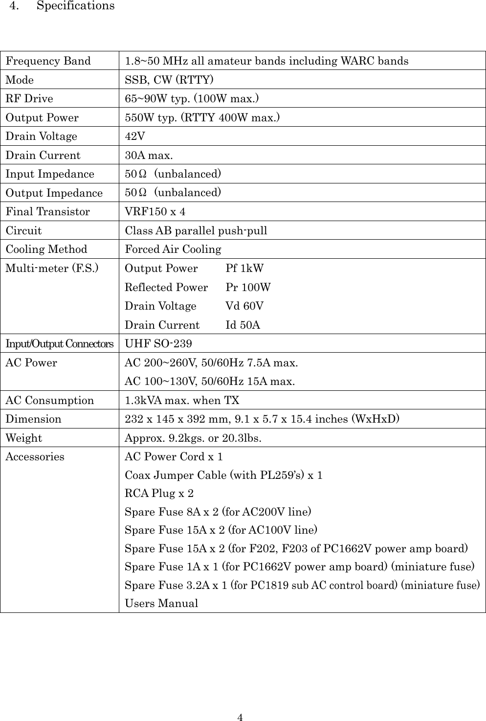
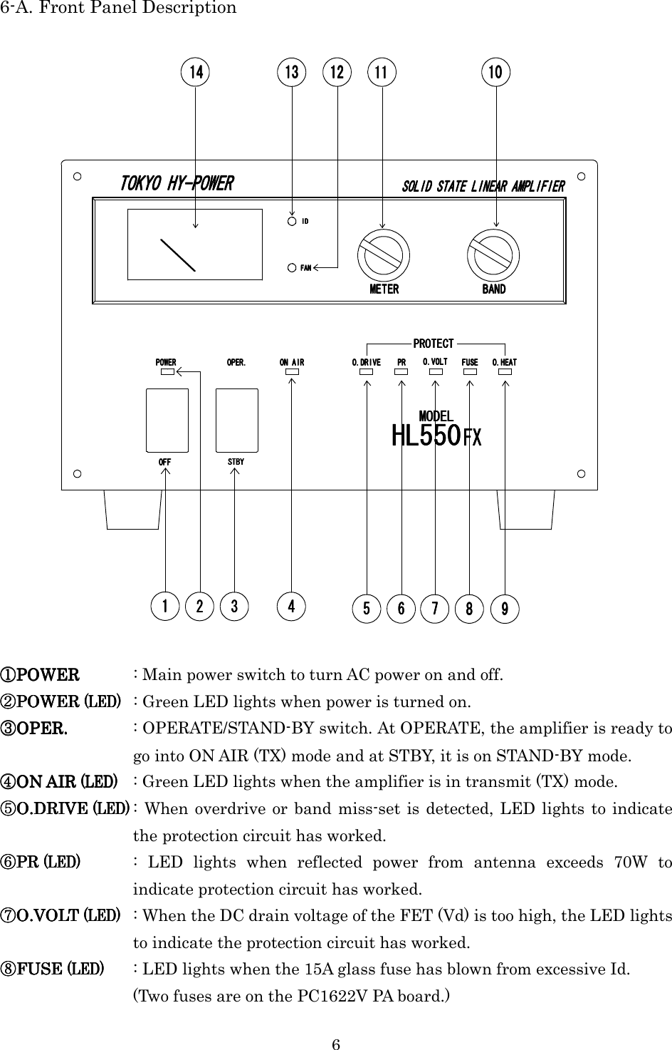
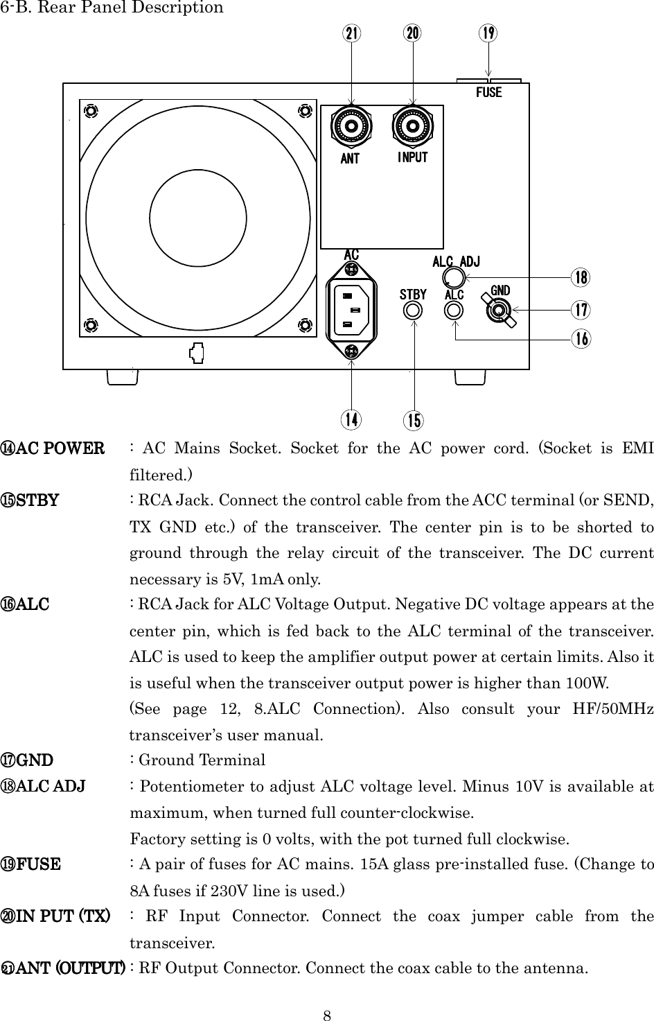
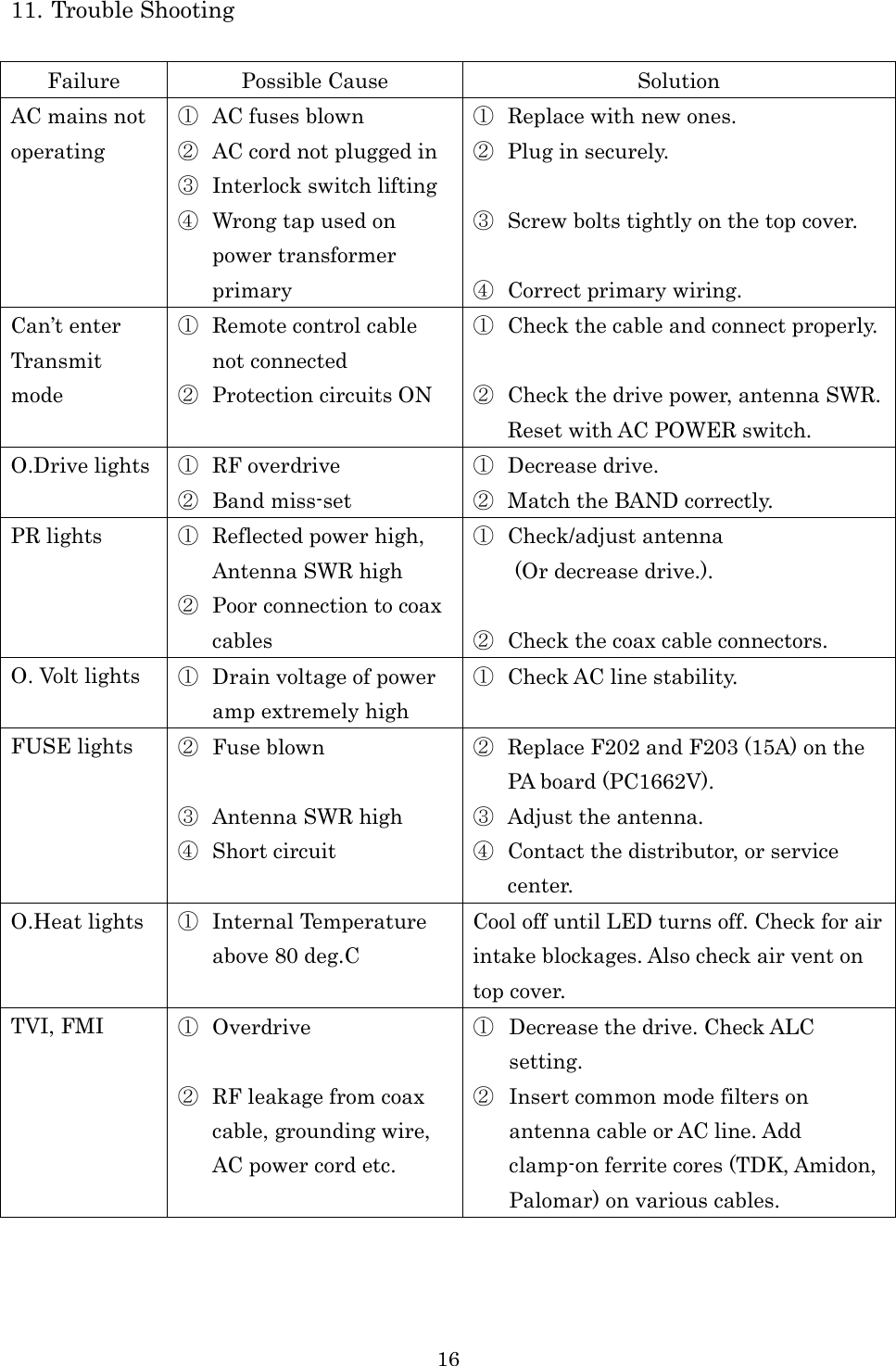
Tokyo Hy-Power Labs, Inc. 550W HF LINEAR AMPLIFIER Users Manual
UserManual.wiki
>
Tokyo Hy Power Labs
>
HL 550FX User Manual
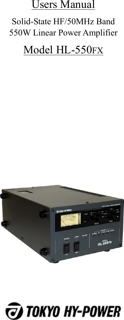
Users Manual
Navigation menu
Upload a User Manual
Namespaces
Wiki Guide
HTML
PDF
Info
Views
User Manual
Discussion / Help
Navigation