User Manual

Doc No:
Topic: User Manual of TomTom HD
Traffic Receiver Module Ver: 1.1 Page: 1 / 40
User Manual
of
TomTom HD Traffic Receiver Module

Doc No:
Topic: User Manual of TomTom HD
Traffic Receiver Module Ver: 1.1 Page: 2 / 40
Page 2 of 40
Document History
Version Date Brief Description
1.0 Feb. 25, 2008 New established
1.1 Apr. 7, 2008 Warning phrases added

Doc No:
Topic: User Manual of TomTom HD
Traffic Receiver Module Ver: 1.1 Page: 3 / 40
Page 3 of 40
FCC Regulations:
z This device complies with part 15 of the FCC Rules. Operation is subject to the following two
conditions: (1) This device may not cause harmful interference, and (2) this device must accept
any interference received, including interference that may cause undesired operation.
z This device has been tested and found to comply with the limits for a Class B digital device,
pursuant to Part 15 of the FCC Rules. These limits are designed to provide reasonable
protection against harmful interference in a residential installation. This equipment generates,
uses and can radiated radio frequency energy and, if not installed and used in accordance with
the instructions, may cause harmful interference to radio communications. However, there is no
guarantee that interference will not occur in a particular installation If this equipment does cause
harmful interference to radio or television reception, which can be determined by turning the
equipment off and on, the user is encouraged to try to correct the interference by one or more of
the following measures:
Reorient or relocate the receiving antenna.
Increase the separation between the equipment and receiver.
Connect the equipment into an outlet on a circuit different from that to which the receiver is
connected.
Consult the dealer or an experienced radio/TV technician for help.
Changes or modifications not expressly approved by the party responsible for compliance could void
the user‘s authority to operate the equipment.
z This device complies with FCC radiation exposure limits set forth for an uncontrolled
environment. In order to avoid the possibility of exceeding the FCC radio frequency exposure
limits, human proximity to the antenna shall not be less than 20cm (8 inches) during normal
operation.

Doc No:
Topic: User Manual of TomTom HD
Traffic Receiver Module Ver: 1.1 Page: 4 / 40
Page 4 of 40
Warning:
The maximum antenna gain allowed for use with this device is -0.81 dBi.
When the module is installed in the host device, the FCC ID label must be visible through a
window on the final device or it must be visible when an access panel, door or cover is easily
removed. If not, a second label must be placed on the outside of the final device that
contains the following text: “Contains FCC ID: S4L-HDTM"

Doc No:
Topic: User Manual of TomTom HD
Traffic Receiver Module Ver: 1.1 Page: 5 / 40
Page 5 of 40
Table of Contents
1. INTRODUCTION............................................................................................................................. 6
2. GENERAL PRODUCT DESCRIPTION .......................................................................................... 7
2.1 SIM Card Holder Support................................................................................................................ 7
2.2 Supply voltage................................................................................................................................. 7
2.3 Power consumption......................................................................................................................... 7
2.4 SIM reader....................................................................................................................................... 8
2.5 Data transmission............................................................................................................................ 8
2.6 Logic level specifications................................................................................................................. 8
2.7 Reset signal..................................................................................................................................... 9
2.8 2.75V_out power output .................................................................................................................. 9
2.9 Connector interface ....................................................................................................................... 10
2.9.1 Board-to-board connector interface......................................................................................... 10
2.9.2 FPC connector interface.......................................................................................................... 10
2.9.3 Interface description ................................................................................................................ 11
2.10 Operating Frequency.................................................................................................................... 11
2.11 GPRS mode ................................................................................................................................. 12
2.12 Transmitter output power ............................................................................................................. 12
2.12.1 GSM–850/900........................................................................................................................ 12
2.12.2 DCS–1800/PCS –1900.......................................................................................................... 12
2.13 Reference sensitivity .................................................................................................................... 13
2.13.1 GSM–850/900........................................................................................................................ 13
2.13.2 DCS–1800/PCS–1900........................................................................................................... 13
2.14 Antenna connector ....................................................................................................................... 13
2.15 Power up / down scenarios .......................................................................................................... 13
2.15.1 Turn on the module................................................................................................................ 13
2.15.3 Turn off the module................................................................................................................ 13
2.15.4 Turn off The module using AT command .............................................................................. 14
2.15.5 Inserted and removal action direction.................................................................................... 14
3. GETTING STARTED..................................................................................................................... 15
3.1 System requirement ....................................................................................................................... 15
3.2 Driver installation............................................................................................................................ 15
3.3 Modem setting................................................................................................................................ 15
3.4 Network setting............................................................................................................................... 26
3.5 Dial-up network by HD Traffic Receiver......................................................................................... 33
3.6 How to setup Hyper Terminal for AT commands ........................................................................... 35
ANNEX A - AT COMMAND SET FOR HD TRAFFIC RECEIVER MODULE ...................................... 37

Doc No:
Topic: User Manual of TomTom HD
Traffic Receiver Module Ver: 1.1 Page: 6 / 40
Page 6 of 40
1. Introduction
HD Traffic Receiver Module is a GPRS modem module. It is a small, lightweight, low power
consumption and RoHS compliant device that allow digital communication services wherever a GSM
850, 900, DCS 1800 or PCS 1900 network is present.
The module is provided with a 20-pin board-to-board connector or 12 pins FPC connector. Power
input connector is necessary when link the modem PCB with 12 pins FPC connector. It also
provides a 50 Ohm Murata RF test port and antenna contact pads.
From the interface point of view, the module provides the following:
z RS232 UART interface
z Two wires RS232 interface
z 2.75V output power source
z 1.8V/3.0V SIM card holder
z System reset
z Power ON/OFF function
z System power interface
Doc No:
Topic: User Manual of TomTom HD
Traffic Receiver Module Ver: 1.1 Page: 7 / 40
Page 7 of 40
2. General Product Description
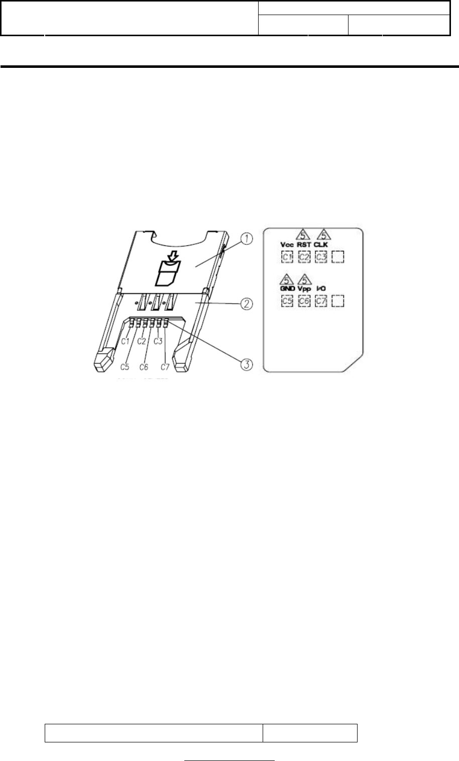
2.1 SIM Card Holder Support
The HD Traffic Receiver Module has on the backside of the PCB, the necessary pads to
manually solder a SIM card holder. The type of the SIM card holder to be used is
UNCR2103D006-0 of JESS-LINK.
2.2 Supply voltage
The external power supply must be connected to Vpower signal and must fulfill the
following requirements:
Nominal operating voltage 3.8 V•
Operating voltage range 3.•4 V - 4.2 V
NOTE: 1. Operating voltage range must never be exceeded; care must be taken in order to fulfill
min/max voltage requirements.
2. The minimum transmission burst voltage in worst network conduction should be kept 3.1V
above.
2.3 Power consumption
The typical current consumption of HD Traffic Receiver Module is:
Power off current (Typical) <= 60 uA

Doc No:
Topic: User Manual of TomTom HD
Traffic Receiver Module Ver: 1.1 Page: 8 / 40
Page 8 of 40
Stand-by current (GSM idle) <= 4 mA
Operating current in GSM channel <= 300 mA
Operating current in GPRS class 10 <= 500 mA
2.4 SIM reader
The HD Traffic Receiver Module support phase 2 GSM11.14 - SIM 1.8V/3V volts.
2.5 Data transmission
The HD Traffic Receiver Module supports GPRS Class 10, MS Class B.
2.6 Logic level specifications
Where not specifically stated, all the interface circuits work at 2.8V CMOS logic levels.
The following table shows the logic level specifications used in the module interface circuits:
Absolute Maximum Ratings –Not Functional
Parameter Min Max
Input level on any digital pin when on - 0.3 V + 3.75 V
Input voltage on any analog pins when on - 0.3 V + 3.0 V
Operating Range –Interface level (2.8V CMOS)
Level Min Max
Input high level 2.1 V 3.3 V
Input low level 0 V 0.5 V
Output high level 2.2 V 3.0 V
Output low level 0 V 0.35 V
Operating Range –Interface level (2.0V CMOS)
Level Min Max
Input high level 1.6 V 3.3 V

Doc No:
Topic: User Manual of TomTom HD
Traffic Receiver Module Ver: 1.1 Page: 9 / 40
Page 9 of 40
Input low level 0 V 0.4 V
Output high level 1.65 V 2.2 V
Output low level 0 V 0.35 V
2.7 Reset signal
RESET signal is used to reset the HD Traffic Receiver Module. Whenever this signal is pulled
low, the module is reset. When the device is reset it stops any operation and after the release
of the reset it is unconditionally rebooted, without doing any detach operation from the network
where it is registered. This behavior is not like a proper shut down because any GSM device is
requested to issue a detach request on turn off. For this reason the Reset signal must not be
used to normally shutting down the device, but only as an emergency exit in the rare case the
device remains stuck waiting for some network response.
The RESET is internally controlled on start-up to achieve always a proper power-on reset
sequence, so there's no need to control this pin on start-up. It may only be used to reset a
device already on that is not responding to any command.
Reset Signal Operating levels:
Signal Min Max
RESET Input high 2.2 V* 3.3 V
RESET Input low 0 V 0.2 V
* This signal is internally pulled up so the pin can be left floating if not used
If unused, this signal may be left unconnected. If used, then it must always be connected
with an open collector transistor, to allow the internal circuitry the power on reset and under
voltage lockout functions.
2.8 2.75V_out power output
A regulated power supply output is provided in order to supply small devices from module. This
output is active when the module is ON and goes off when module is shut down. The operating
range characteristics of the supply are:
Operating Range –2.75V_out power supply
Min Typical Max
Output voltage 2.75 V 2.85 V 2.95 V

Doc No:
Topic: User Manual of TomTom HD
Traffic Receiver Module Ver: 1.1 Page: 10 / 40
Page 10 of 40
Output current 50 mA
Output bypass capacitor 2.2 uF
2.9 Connector interface
2.9.1 Board-to-board connector interface
PIN Definition
GND 1 2 GND
Vpower 3 4 Vpower
Vpower 5 6 Vpower
GND 7 8 GND
SYS_EN 9 10 VINT
GND 11 12 GND
EXT_RST 13 14 CTS_0
GND 15 16 RTS_0
RXD_1 17 18 RXD_0
TXD_1 19 20 TXD_0
2.9.2 FPC connector interface
PIN Define
1 GND
2 VINT
3 GND
4 EXT_RST
5 SYS_EN
6 GND
7 CTS_0
8 RTS_0
9 TXD_0
10 TXD_1
11 RXD_0
12 RXD_1

Doc No:
Topic: User Manual of TomTom HD
Traffic Receiver Module Ver: 1.1 Page: 11 / 40
Page 11 of 40
2.9.3 Interface description
PIN Name I/O Function I/O type Description
1 GND PWR GSM Power Supply Ground Power GND
2 GND PWR GSM Power Supply Ground Power GND
3 Vpower PWR GSM Power Supply From 3.4 to 4.2 V
(Typical: 3.8 V) Input power for System
4 Vpower PWR GSM Power Supply From 3.4 to 4.2 V
(Typical: 3.8 V) Input power for System
5 Vpower PWR GSM Power Supply From 3.4 to 4.2 V
(Typical: 3.8 V) Input power for System
6 Vpower PWR GSM Power Supply From 3.4 to 4.2 V
(Typical: 3.8 V) Input power for System
7 GND PWR GSM Power Supply Ground Power GND
8 GND PWR GSM Power Supply Ground Power GND
9 SYS_EN I Power on/off system CMOS 3.3V
compatible
When SYS_EN is high,
the system will power
on
10 2.75V_out O 2.75V Output 2.75V Output
The range of
2.75V_out is between
2.62V and 2.82V
11 GND PWR GSM Power Supply Ground Power GND
12 GND PWR GSM Power Supply Ground Power GND
13 EXT_RST I External reset CMOS 3.3V
compatible External HW reset
14 CTS_0 I Asynchronous Serial
Interface 0 CMOS 3.3V
compatible RTS (DCE)
15 GND PWR GSM Power Supply Ground Power GND
16 RTS_0 O Asynchronous Serial
Interface 0 CMOS 3.3V
compatible CTS (DCE)
17 RXD_1 I Asynchronous Serial
Interface 1 CMOS 3.3V
compatible RX (DCE)
18 RXD_0 I Asynchronous Serial
Interface 0 CMOS 3.3V
compatible RX (DCE)
19 TXD_1 O Asynchronous Serial
Interface 1 CMOS 3.3V
compatible TX (DCE)
20 TXD_0 O Asynchronous Serial
Interface 0 CMOS 3.3V
compatible TX (DCE)
2.10 Operating Frequency

Doc No:
Topic: User Manual of TomTom HD
Traffic Receiver Module Ver: 1.1 Page: 12 / 40
Page 12 of 40
The Module supports GSM 850/900/1800/1900 Quad Band.
Mode Freq. TX (MHz) RX (MHz)
GSM-850 TX: 824.2 - 848.8MHz RX: 869.2 - 893.8MHz
GSM-900 TX: 880.2 - 914.8MHz RX: 925.2 - 959.8MHz
DCS-1800 TX: 1710.2 - 1784.8MHz RX: 1805.2 - 1879.8MHz
PCS-1900 TX: 1850.2 - 1909.8MHz RX: 1930.2 - 1989.8MHz
2.11 GPRS mode
The Module compliant with GMS/GPRS protocol stack R.99
• GPRS multi-slot class 10
• MS class B
• Coding scheme 1-4
2.12 Transmitter output power
2.12.1 GSM–850/900
The Module in GSM–850/900 operating mode are class 4 in accordance with the specifications
that determine the nominal 2W peak RF power (+33dBm) on 50-Ohm load.
2.12.2 DCS–1800/PCS –1900
The module in DCS–1800/PCS–1900 operating mode are class 1 in accordance with the
specifications that determine the nominal 1W peak RF power (+30dBm) on 50-Ohm load.

Doc No:
Topic: User Manual of TomTom HD
Traffic Receiver Module Ver: 1.1 Page: 13 / 40
Page 13 of 40
2.13 Reference sensitivity
2.13.1 GSM–850/900
The sensitivity of the GSM-850/GSM-900 according to the specifications for the class 4 is -
109dBm typical in normal operating conditions.
2.13.2 DCS–1800/PCS–1900
The sensitivity of the DCS–1800/PCS–1900 according to the specifications for the class 1 is -
108dBm typical in normal operating conditions.
2.14 Antenna connector
The Module is equipped with a 50 Ohm RF connector from Murata P/N MM9329-2700B.
Moreover, it has the antenna pads on the PCB to accept spring clips for antenna contact.
2.15 Power up / down scenarios
In general, be sure not to turn on the module while it is out of the operating range of voltage in
Chapter 2.2.
2.15.1 Turn on the module
The module can be activated via SYS_EN signal. When switch on the Module the SYS_EN signal
needs to be driven to high level for at least 150ms
2.15.3 Turn off the module
To switching the module off the following procedures may be used:
* Normal shutdown:

Doc No:
Topic: User Manual of TomTom HD
Traffic Receiver Module Ver: 1.1 Page: 14 / 40
Page 14 of 40
Software controlled by sending the AT command over the serial application interface.
* Automatic shutdown:
Takes effect if under voltage is detected.
2.15.4 Turn off The module using AT command
The best and safest approach to powering down the module is to issue the AT command. This
procedure let the module log off from network and allows the software to enter into a secure
state and safe data before disconnecting the power supply. The mode is referred to as POWER
OFF mode. In this mode, only the RTC stays active.
Command syntax: AT+CPWROFF
Command Possible responses
AT+CPWROFF
Note: switch off the module
OK
Or
CME ERROR: <error>
Test command
AT+CPWROFF=?
OK
After sending AT+CPWROFF do not enter any other AT command. There are two ways to verify
when the module turns off.
* Wait for the “OK”. It indicates that data have been stored in the non-volatile memory and
the module turn off in less than 1 second.
* Also, you can monitor the 2.75V_out pin. The low state of 2.75V_out definitely that the
module is switched off.
When the module is in POWER OFF mode the application interface is switched off and must not
be fed from any other source. Therefore, your application must be designed to avoid any current
flow into any digital pins of the application interface.
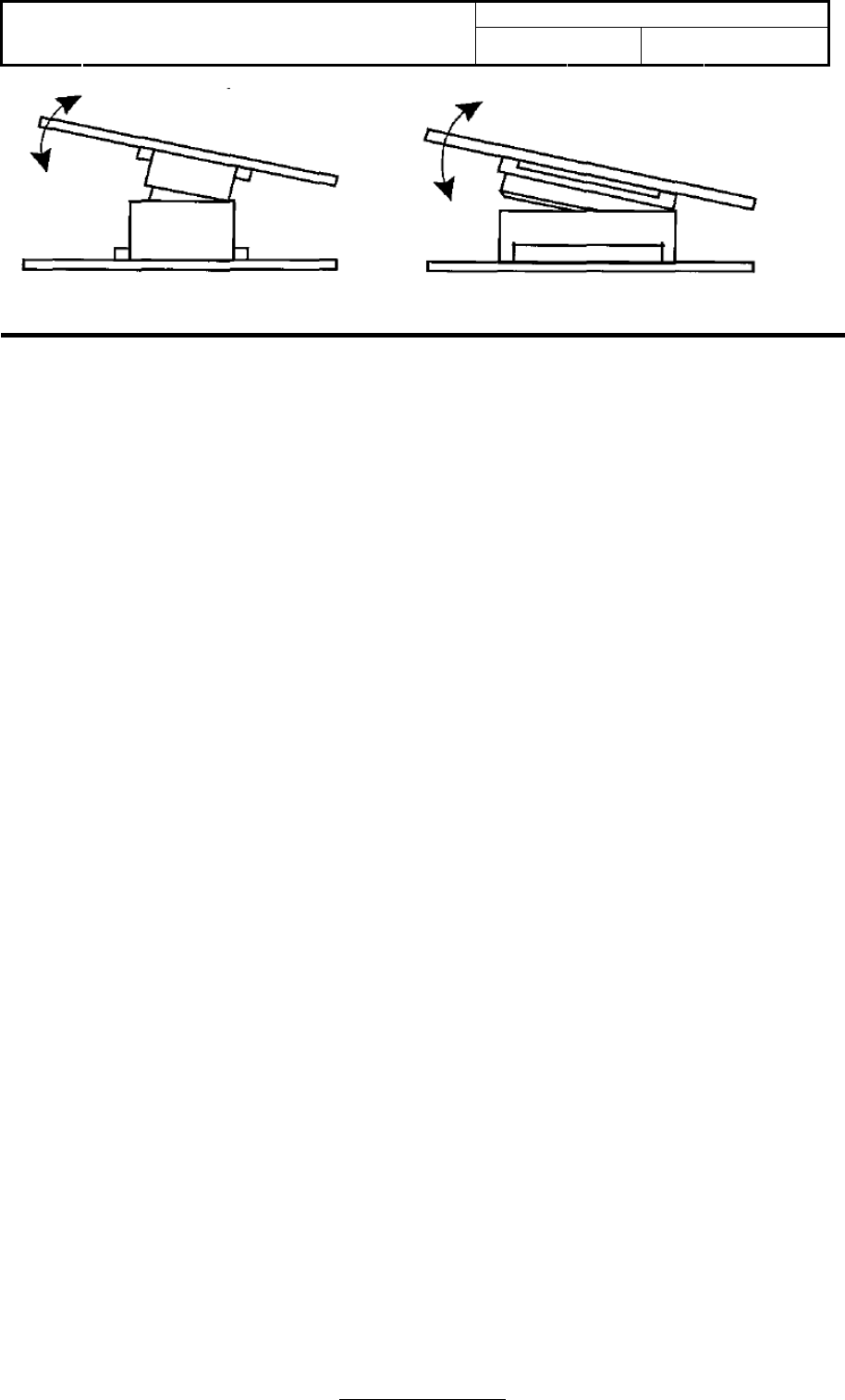
2.15.5 Inserted and removal action direction
These models are made very thin so that they may be smaller in size and light in weight than
before. Take care not to give then excessive force and insert by sliding when mating them
together or un-mating them. Otherwise, breakage may result. To prevent damage from incorrect
insertions please confirm the correct position before mating connection.
Doc No:
Topic: User Manual of TomTom HD
Traffic Receiver Module Ver: 1.1 Page: 15 / 40
Page 15 of 40
3. Getting Started
3.1 System requirement
The following shows the operation by PC with Microsoft Window 2000, XP or Vista. The screen
display for each procedure may be a little different for different operating system.
3.2 Driver installation
Please install “CP210x_VCP_Win2K_XP_S2K” driver on your PC before doing your Modem setting.
The driver is for Silicon Laboratories’ CP210X USB to UART Bridge chip in the device.
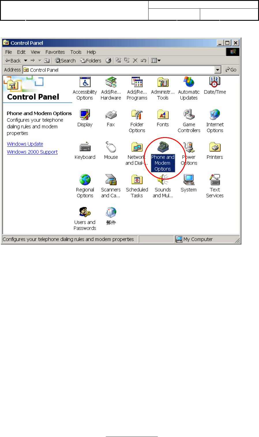
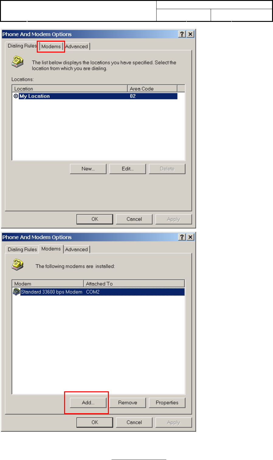
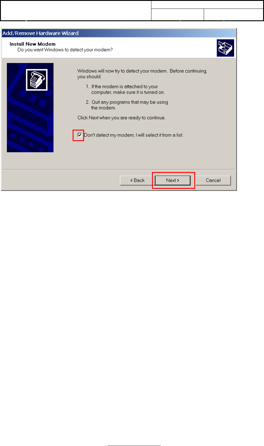
3.3 Modem setting
Please use “Control Panel” to install new modem.
Doc No:
Topic: User Manual of TomTom HD
Traffic Receiver Module Ver: 1.1 Page: 16 / 40
Page 16 of 40
Doc No:
Topic: User Manual of TomTom HD
Traffic Receiver Module Ver: 1.1 Page: 17 / 40
Page 17 of 40
Doc No:
Topic: User Manual of TomTom HD
Traffic Receiver Module Ver: 1.1 Page: 18 / 40
Page 18 of 40
1
2
Doc No:
Topic: User Manual of TomTom HD
Traffic Receiver Module Ver: 1.1 Page: 19 / 40
Page 19 of 40
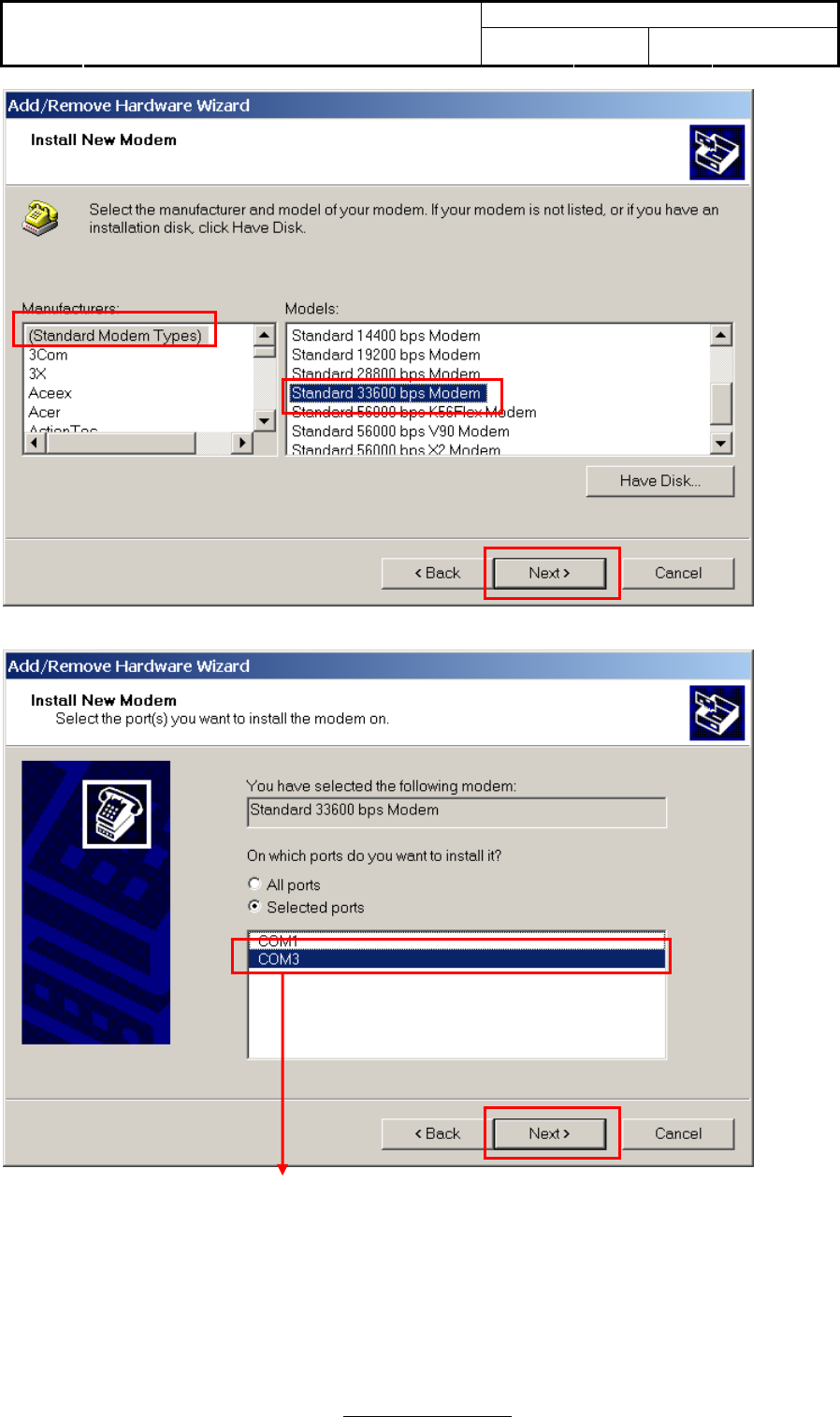
Select the COM port that you have installed “CP210x_VCP_Win2K_XP_S2K3” driver. For example:
COM3 in the installation demo.
2
3
1
1
2
Doc No:
Topic: User Manual of TomTom HD
Traffic Receiver Module Ver: 1.1 Page: 20 / 40
Page 20 of 40
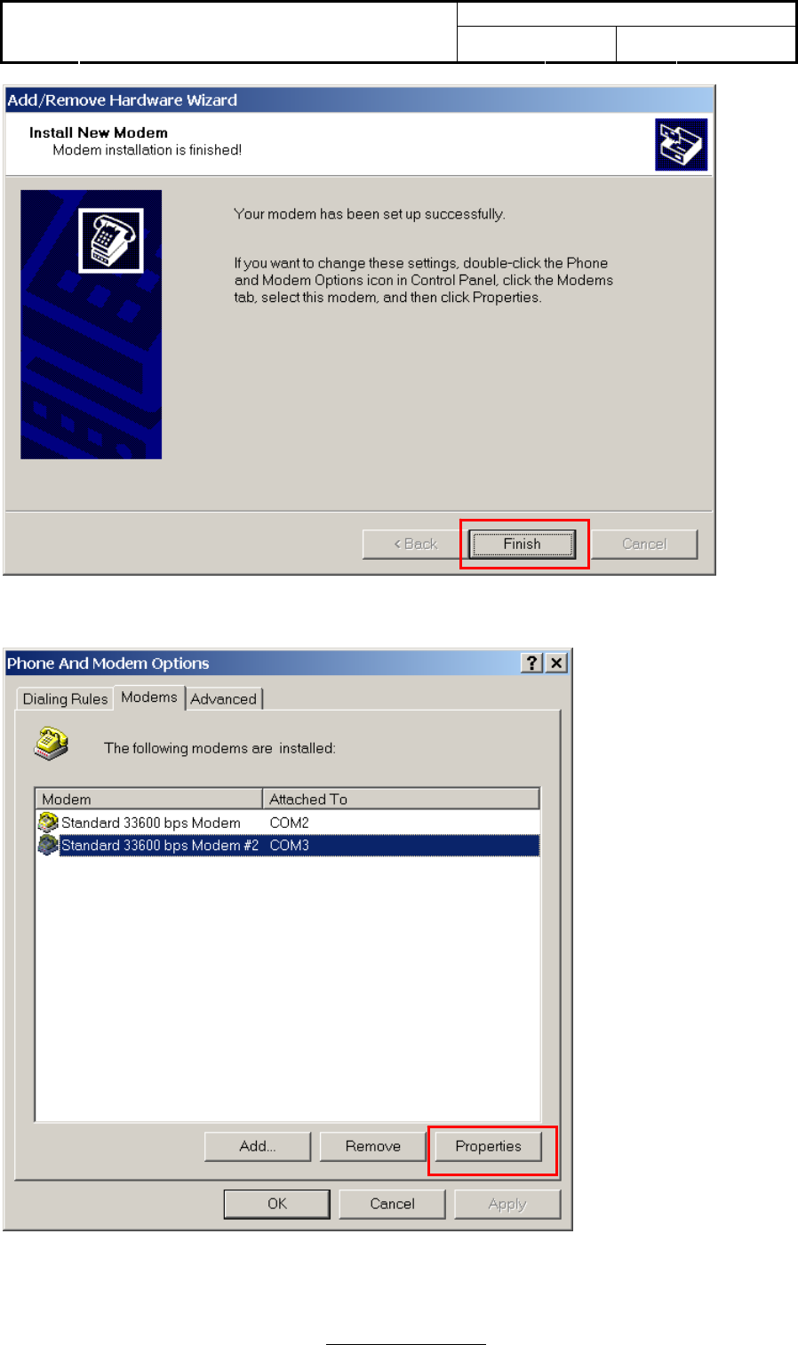
Your modem has been set up for the first step.
Next step, we will run advanced setting of modem.

Doc No:
Topic: User Manual of TomTom HD
Traffic Receiver Module Ver: 1.1 Page: 21 / 40
Page 21 of 40
Doc No:
Topic: User Manual of TomTom HD
Traffic Receiver Module Ver: 1.1 Page: 22 / 40
Page 22 of 40
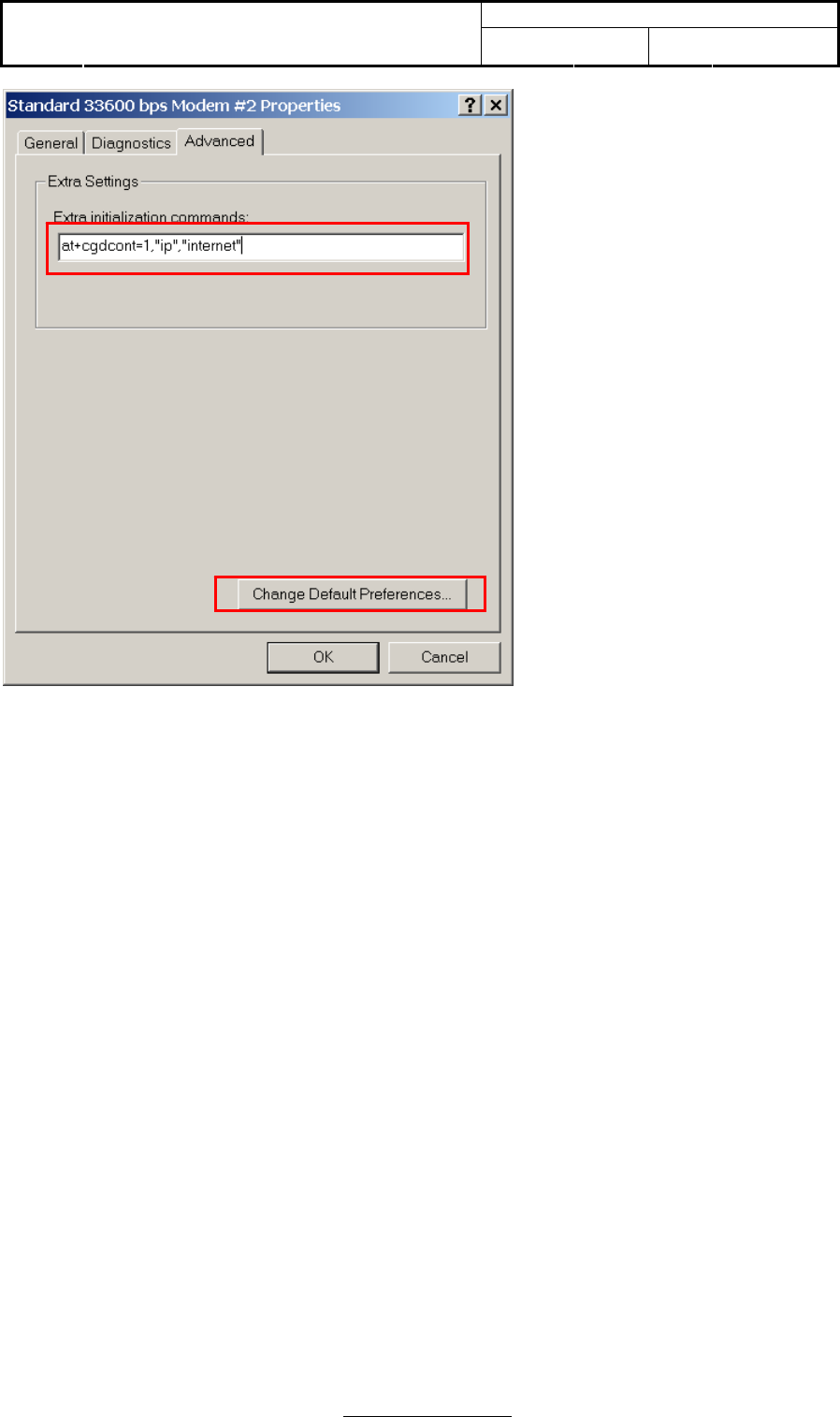
Typing into “at+cgdcont=1, “ip”, “internet” for extra initialization commands.
This command allows to specify specific PDP context parameter values for a PDP context.
1
2
Doc No:
Topic: User Manual of TomTom HD
Traffic Receiver Module Ver: 1.1 Page: 23 / 40
Page 23 of 40
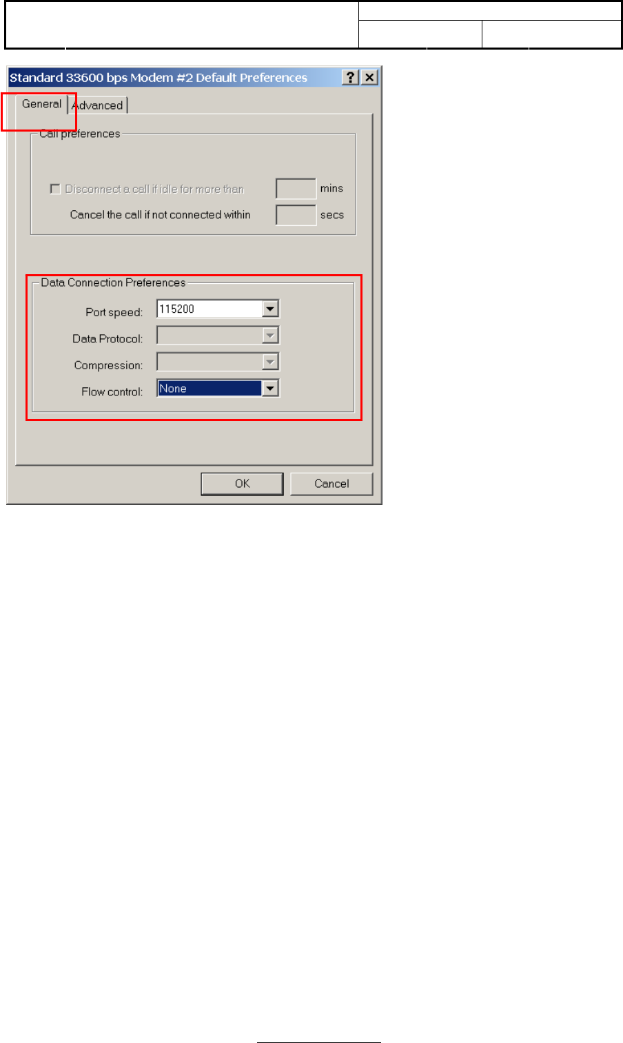
Please make sure that the flow control is “None”.
2
1
Doc No:
Topic: User Manual of TomTom HD
Traffic Receiver Module Ver: 1.1 Page: 24 / 40
Page 24 of 40
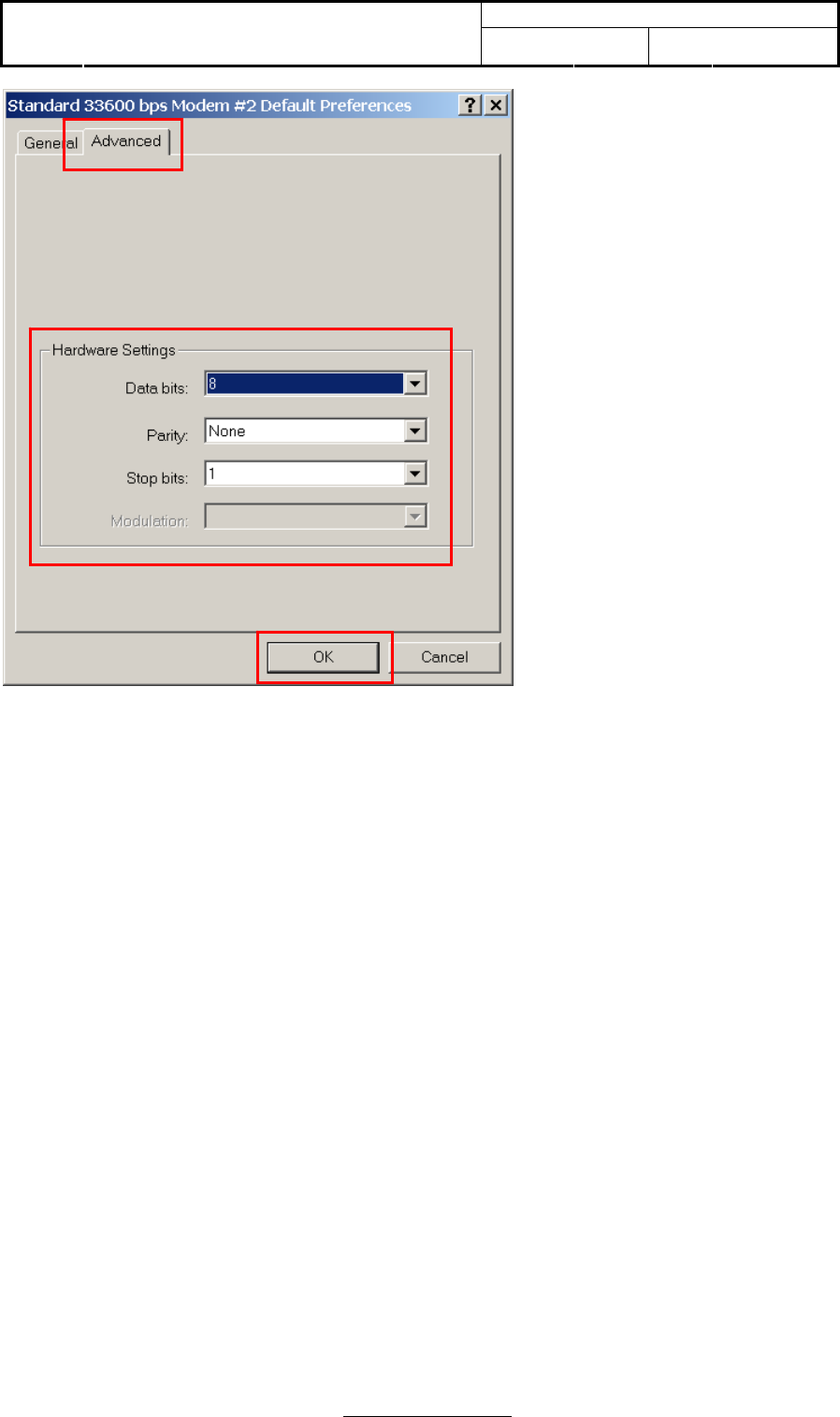
Please make sure that hardware settings are the same as above.
1
2
Doc No:
Topic: User Manual of TomTom HD
Traffic Receiver Module Ver: 1.1 Page: 25 / 40
Page 25 of 40
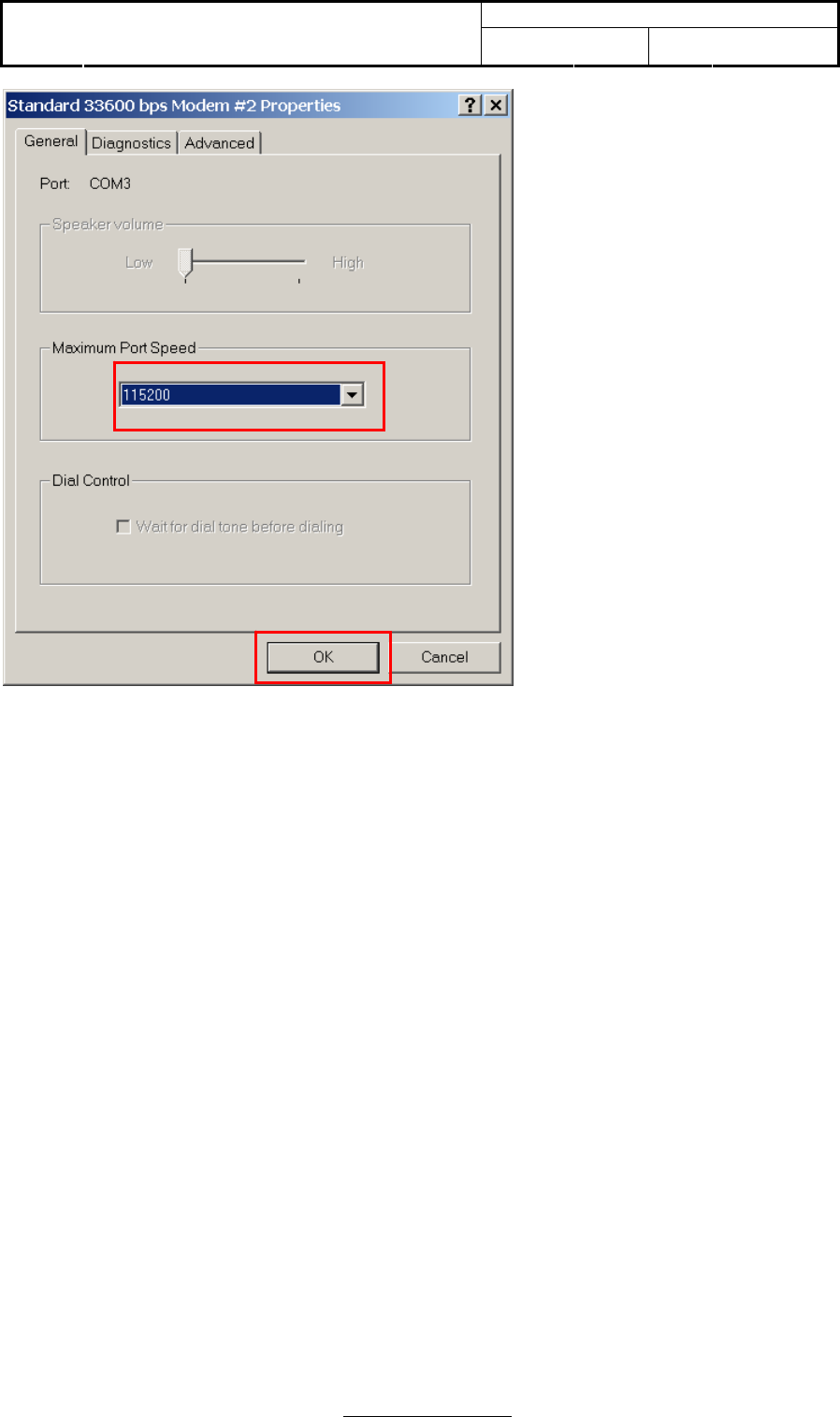
Please make sure maxmun port speed to be 115200.
Doc No:
Topic: User Manual of TomTom HD
Traffic Receiver Module Ver: 1.1 Page: 26 / 40
Page 26 of 40
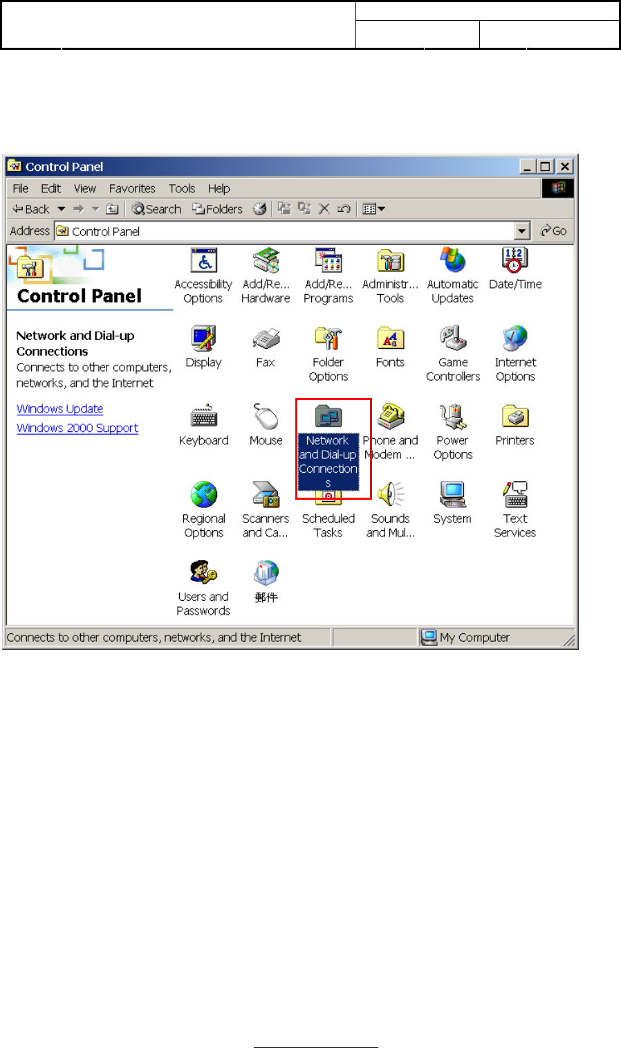
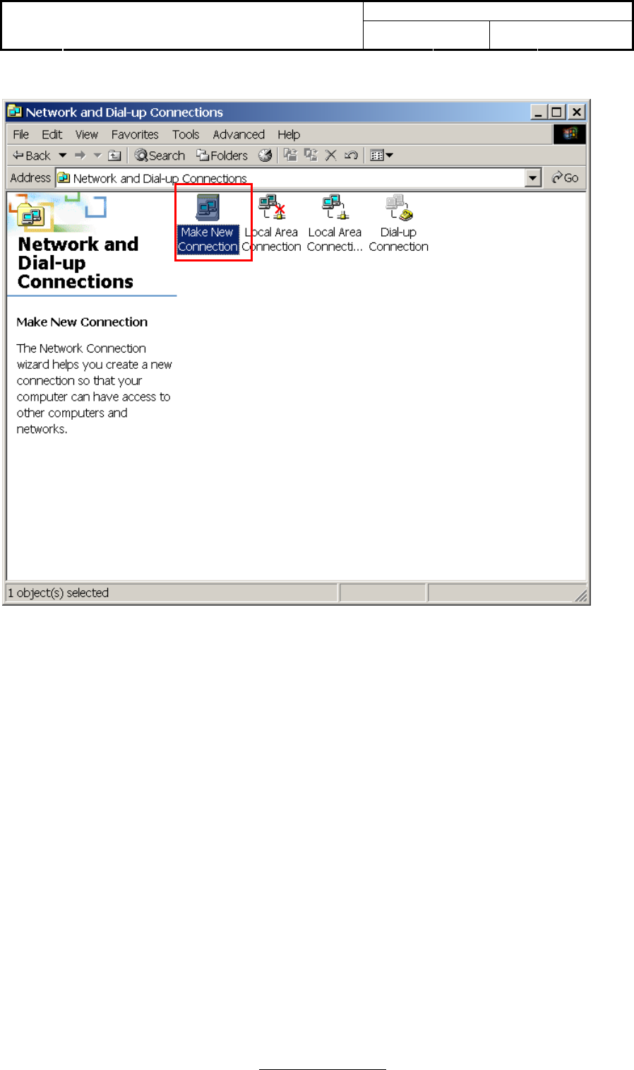
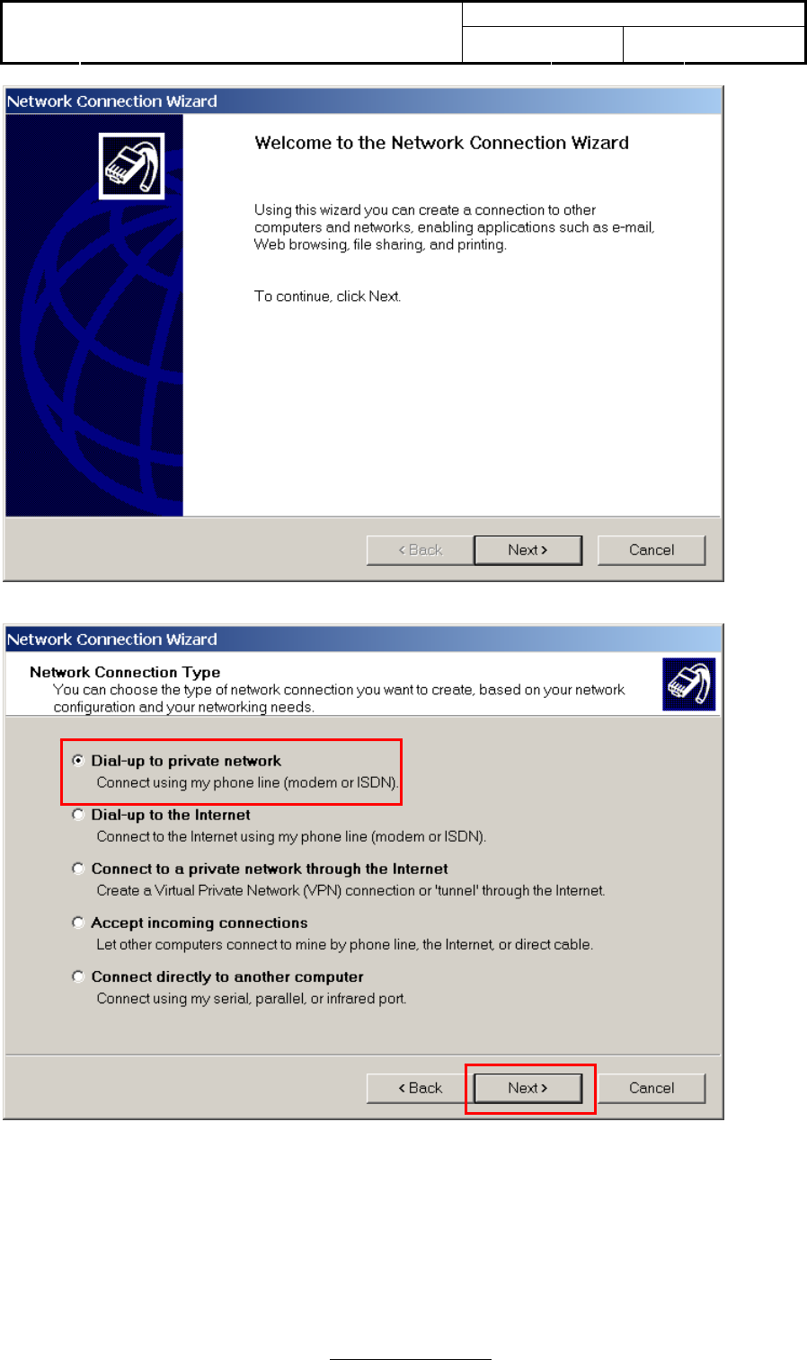
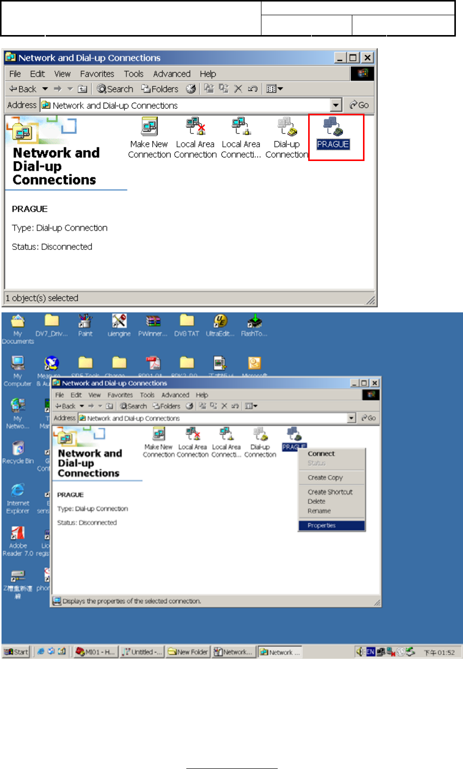
3.4 Network setting
Double click “Network and Dial-up Connections” icon to run network setting.
Doc No:
Topic: User Manual of TomTom HD
Traffic Receiver Module Ver: 1.1 Page: 27 / 40
Page 27 of 40
Doc No:
Topic: User Manual of TomTom HD
Traffic Receiver Module Ver: 1.1 Page: 28 / 40
Page 28 of 40
Doc No:
Topic: User Manual of TomTom HD
Traffic Receiver Module Ver: 1.1 Page: 29 / 40
Page 29 of 40
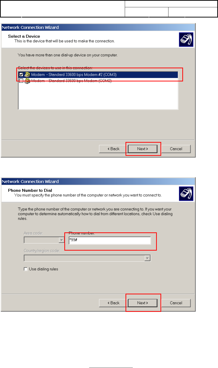
Please type “*99#” into phonebook number.
1
2
3
4
Doc No:
Topic: User Manual of TomTom HD
Traffic Receiver Module Ver: 1.1 Page: 30 / 40
Page 30 of 40
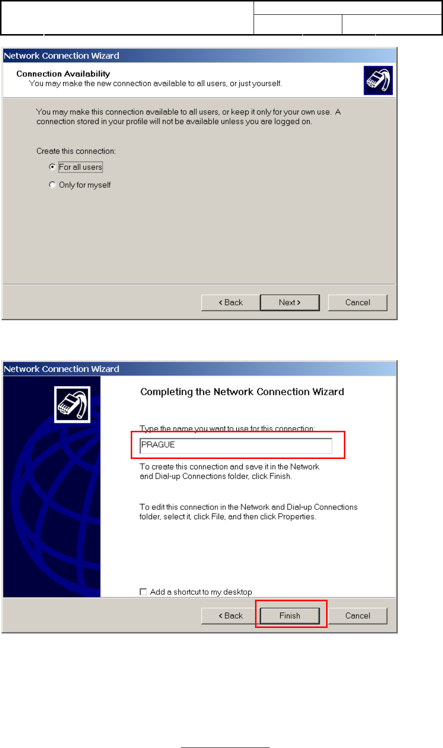
Type the name you want to use for this connection. For example: Prague
Doc No:
Topic: User Manual of TomTom HD
Traffic Receiver Module Ver: 1.1 Page: 31 / 40
Page 31 of 40
Pressing the right button of mouse on “Prague” connection icon, you need to change the properties.
Doc No:
Topic: User Manual of TomTom HD
Traffic Receiver Module Ver: 1.1 Page: 32 / 40
Page 32 of 40
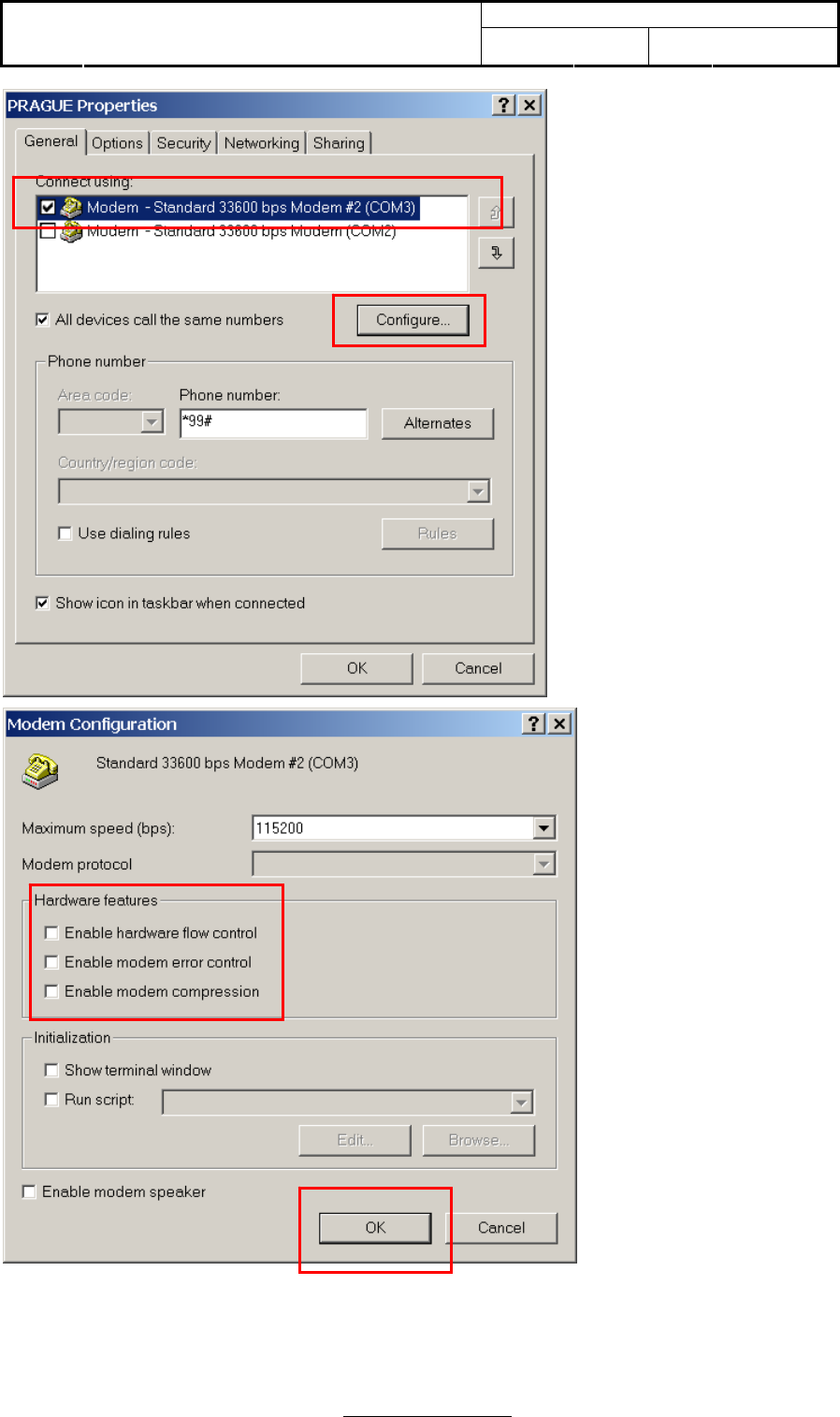
All hardware features of modem protocol should be disabled. Now, you have completed all modem
and network setting. You can use Section 2.3 to dial up network directly in the future.
1
2
3
4
Doc No:
Topic: User Manual of TomTom HD
Traffic Receiver Module Ver: 1.1 Page: 33 / 40
Page 33 of 40
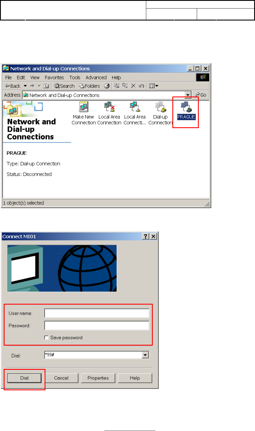
3.5 Dial-up network by HD Traffic Receiver
Pressing “Prague” icon to dial up network.
Keep empty for user name and password.
Doc No:
Topic: User Manual of TomTom HD
Traffic Receiver Module Ver: 1.1 Page: 34 / 40
Page 34 of 40
Doc No:
Topic: User Manual of TomTom HD
Traffic Receiver Module Ver: 1.1 Page: 35 / 40
Page 35 of 40
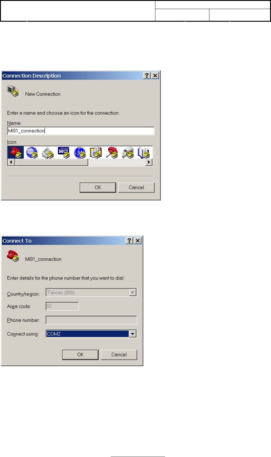
3.6 How to setup Hyper Terminal for AT commands
Run Hyper Terminal from Windows XP Start->Programs->Accessories->Communications->Hyper
Terminal
Set the name for connection (e.g. “MI01_connection”), then press OK
Select the PC serial port (for example COM2) , then press OK
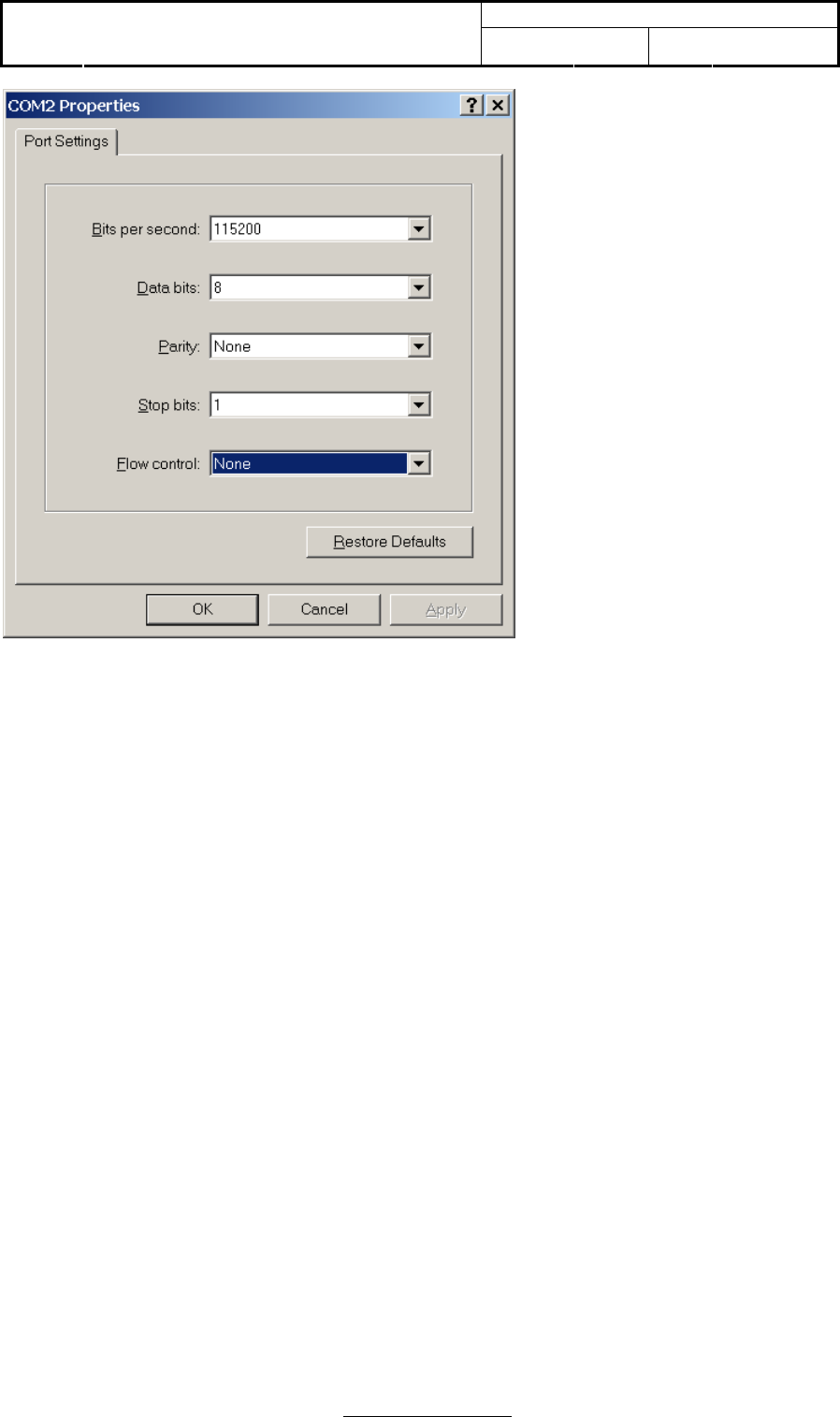
Select the appropriate setting for MI01 data modem serial port setting; then select APPLY/OK.
Doc No:
Topic: User Manual of TomTom HD
Traffic Receiver Module Ver: 1.1 Page: 36 / 40
Page 36 of 40
If the HD Traffic Receiver module is power up, you type AT then the response must be OK.

Doc No:
Topic: User Manual of TomTom HD
Traffic Receiver Module Ver: 1.1 Page: 37 / 40
Page 37 of 40
Annex A - AT command set for HD Traffic Receiver Module
1. General commands
Manufacturer identification +CGMI
Request model identification +CGMM
Request revision identification +CGMR
Request product serial number identification +CGSN
Set TE character set +CSCS
Request international mobile subscriber identification +CIMI
Card identification +CCID
Request complete capabilities list +GCAP
Repeat last command A/
2. Call control commands
Select type of address +CSTA
Dial command D
Select tone dialing T
Select pulse dialing P
Call answer A
Hook control H
Monitor speaker loudness L
Monitor speaker mode M
Call mode +CMOD
Hangup call +CHUP
Extended error report +CEER
Tone duration +VTD
DTMF and tone generation +VTS
Redial last telephone number ATDL
Automatic answer S0
3. Network service commands
Subscriber number +CNUM
Signal quality +CSQ
Operator selection +COPS
Network registration +CREG
Preferred operator list +CPOL
Read operator names +COPN
4. Security commands
Enter PIN +CPIN
Facility lock +CLCK
Change password +CPWD
5. Mobile equipment control and status commands
Phone activity status +CPAS
Switch off MS +CPWROFF
Set phone functionality +CFUN
Battery charge +CBC
Indicator control +CIND
Mobile termination event reporting +CMER
Clock +CCLK
Alarm +CALA
Delete alarm +CALD
Restricted SIM access +CRSM
Alert sound mode +CALM
Ringer sound level +CRSL
Speech volume level +CLVL
Mute control +CMUT

Doc No:
Topic: User Manual of TomTom HD
Traffic Receiver Module Ver: 1.1 Page: 38 / 40
Page 38 of 40
Call meter maximum event +CCWE
Set greeting text +CSGT
Automatic Time Zone Update +CTZU
Time Zone Reporting +CTZR
Report mobile termination error +CMEE
List all available AT commands +CLAC
6. Phonebook commands
Select phonebook memory storage +CPBS
Read phonebook entries +CPBR
Find phonebook entries +CPBF
Write phonebook entry +CPBW
7. Short messages commands
Select message service +CSMS
Preferred message storage +CPMS
Preferred message format +CMGF
Save settings +CSAS
Restore Settings +CRES
Show text mode parameters +CSDH
New message indication +CNMI
Read message +CMGR
New Message Acknowledgement to ME/TA +CNMA
List message +CMGL
Send message +CMGS
Write message to memory +CMGW
Send message from storage +CMSS
Set text mode parameters +CSMP
Delete SMS +CMGD
Service center address +CSCA
Select cell broadcast message types +CSCB
8. Supplementary services commands
Call forwarding +CCFC
Call waiting +CCWA
Calling line identification restriction +CLIR
Calling line identification presentation +CLIP
Connected line identification presentation +COLP
Connected line identification restriction +COLR
Advise of charge +CAOC
Accumulated call meter +CACM
Accumulated call meter maximum +CAMM
Price per unit and currency table +CPUC
Call related supplementary services +CHLD
Call deflection +CTFR
List current calls +CLCC
Supplementary service notifications +CSSN
Unstructured supplementary service data +CUSD
Closed user group +CCUG
Calling name presentation +CNAP
9. Data commands
Select bearer service type +CBST
Service class selection and identification +FCLASS
Service reporting control +CR
Cellular result codes +CRC
Radio link protocol +CRLP
10. V24 control and V25ter commands

Doc No:
Topic: User Manual of TomTom HD
Traffic Receiver Module Ver: 1.1 Page: 39 / 40
Page 39 of 40
Reset to default configuration Z
Set to factory defined configuration &F
Circuit 109 behavior &C
Circuit 108/2 behavior &D
DSR override &S
Flow control &K
Store current configuration &W
Display current configuration &V
Designate a default reset profile &Y
Request identification information I
Request manufacturer Identification +GMI
Request model identification +GMM
Request revision identification +GMR
Request product serial number identification +GSN
DTE-DCE character framing +ICF
DTE-DCE local flow control +IFC
Set flow control \Q
Fixed DTE rate +IPR
Return to on-line data state O
Escape character S2
Command line termination character S3
Response formatting character S4
Command line editing character S5
Pause before blind dialing S6
Connection completion timeout S7
Command dial modifier time S8
Automatic disconnect delay S10
Escape prompt delay (EPD) S12
Command echo E
Result code suppression Q
DCE response format V
Result code selection and call progress monitoring control X
11 Specific AT commands
Production test command #
GPRS cell environment description +CGED
Switch trace ON/OFF +TRACE
Select Band +XBANDSEL
Set reporting call status +XCALLSTAT
Display generation and SW version +XGENDATA
Read counters of sent or received GPRS data +XGCNTSET
Set/reset counter of sent or received GPRS data +XGCNTSET
Set hands free mode +XHANDSFREE
Call the L1-specific function +XL1SET
Configuration trace and modem (AT) interfaces +XSIO
ADC read command +NADC
GPIO select configuration command +NGPIOC
GPIO read command +NGPIOR
GPIO set command +NGPIOW
Ringer select command +NRNG
Tone generator +NTGN (Tone GeNerator)
Alert sound mode +NMSM (Message Sound Muting)
Power saving control +NPSV (Power SaVing)
12. GPRS commands
Define PDP context +CGDCONT
GPRS event reporting +CGEREP
Quality of service profile (requested) +CGQREQ
Quality of service profile (minimum acceptable) +CGQMIN
GPRS attach or detach +CGATT

Doc No:
Topic: User Manual of TomTom HD
Traffic Receiver Module Ver: 1.1 Page: 40 / 40
Page 40 of 40
PDP context activate or deactivate +CGACT
Enter data state +CGDATA
Automatic response to a network request for PDP context activation +CGAUTO
Show PDP address +CGPADDR
GPRS mobile station class +CGCLASS
GPRS network registration status +CGREG
Select service for MO SMS messages +CGSMS
13. TCP/IP AT Commands
Packet Switched Data +NPSD
Packet Switched Data Action +NPSDA
Packet Switched Network Assigned Data +NPSND
Circuit Switched Data +NCSD
Circuit Switched Data Action +NCSDA
Circuit Switched Network Assigned Data +NCSND
Create Socket +NSOCR
Set Socket Option +NSOSO
Get Socket Option +NSOGO
Close Socket +NSOCL
Get Socket Error +NSOER
Set Listening Socket +NSOLI
Connect Socket +NSOCO
Write Socket Data +NSOWR
Read Socket Data +NSORD
14. Reference
3GPP TS27.007 Technical Specification Terminals; AT command set for User Equipment (UE);
V3.11.0