TomTom LINK500 Telematic Device User Manual IG EN
TomTom International BV Telematic Device IG EN
TomTom >
UserMan

TomTom LINK 510
Installation Guide
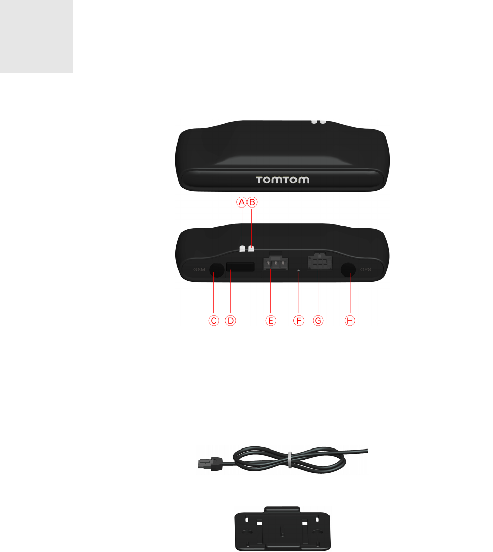
What’s in the box2.
2
What’s
in the
box aTomTom LINK 510
AYellow LED for indication of the connection status
BGreen LED for indication of the system status
CGSM antenna connector (SMB) for optional use of an external GSM antenna
DService/Update Mini-USB-cable connector
EPower cable connector
FReset button
GIO-Cable connector
HGPS antenna connector (SMB) for optional use of an external GPS antenna
bPower cable
cHolder
dFixatives - 2 cable ties, 2 adhesive strips, 2 self-tapping screws and a cleaning tissue

Before the Installation3.
3
Before
the In-
stalla-
tion Congratulations
You have chosen the TomTom LINK 510, a core hardware component of TomTom
WORKsmart fleet management solutions. With WORKsmart from TomTom Business
Solutions you are always connected to your people on the road in a smart and easy way.
TomTom LINK 510 is a GPS receiver and GSM/GPRS module in one unit, always providing
the vehicle’s current position.
When used with a compatible TomTom navigation device*, you will be able to easily
handle orders, as well as text and status messages. You will receive traffic information,
you will be warned when you are driving or cornering too fast and get information about
how much fuel you have used.
What you need for the installation
Before starting the installation of your TomTom LINK 510, read the safety notices and
warnings carefully and make sure you have the following things:
•The TomTom WEBFLEET Contract Confirmation letter including the Activation Code.
• All parts mentioned in the chapter What’s in the box on page 2.
• A connection to the vehicle’s power supply that is fused with max. 10 A.
•A place with clear view of the sky where you can move your vehicle to check GPS
reception.
•A TomTom navigation device that is compatible to TomTom LINK 510* - optional.
*Compatible devices to the LINK 510: All TomTom PRO devices except the PRO 9xxx
series.

Safety first4.
4
Safety
first Important safety notices and warnings
Important: Read the following safety instructions carefully
TomTom Business Solutions accept no liability for damage that results from disregard for
the safety instructions.
This document is part of the product. Keep it in a safe place. If you pass the unit on to a
new user, make sure you give them this document as well.
•Important - damage caused through improper installation
The installation and initial operation of the unit must be performed by authorised
personnel only, e.g. a qualified radio dealer or an automotive electronics workshop.
Consider the quality standards of the motor vehicle trade.
•Caution - risk of injury in case of accidents
Do not mount the unit or accessories in the inflation area of airbags or in the impact area
of the head or knees. Search carefully for an installation location that will avoid
interference with displays, safety equipment and controls.
•Caution - damage to the chassis
Make sure you do not drill into parts of the chassis that have structural or security-
related functions. You cannot be certain that they will function properly after
modification.
•Caution - risk of fire
Make sure you do not drill into covered wiring harnesses, fuel lines or similar
components. Drilling into these can cause fire.
•Caution - use of this product is restricted in some areas
The GSM module of the TomTom LINK 510 is likely to interfere with electric devices
such as cardiac pacemakers, hearing aids, electric devices used in intensive medicine,
and aviation equipment. The interference with these devices can endanger the health
or life of the users. Do not use near unprotected electrical units nor in areas where the
use of mobile telephones is prohibited, such as hospitals and airplanes! Switch off the
unit if there is a danger of interference with such equipment.
•Caution - danger of explosion
Parts of TomTom LINK 510 can cause sparks, which can lead to explosions. This may
endanger human health and life. Do not use the unit in areas with high risk of explosion.
When using TomTom LINK 510 in a vehicle fueled by liquefied gas, follow the safety
regulations of the country in which the vehicle is operated.
•Warning - repair and replacement
5
Repairs must be carried out by authorised and qualified personnel only. Never replace
damaged parts of the unit yourself. Give the defective unit to TomTom Business
Solutions. Only the qualified staff of TomTom Business Solutions are authorised to
repair or replace parts.
•Warning - damage to the device
Short-circuits inside the unit can be caused by contact with water or other liquids. The
unit may be damaged by contact with water. Use and store the unit in an area protected
from water.
•Caution - risk of accidents
Using the unit while driving is distracting and can cause accidents. To ensure road
safety, only enter information in the unit when the vehicle is not being driven.
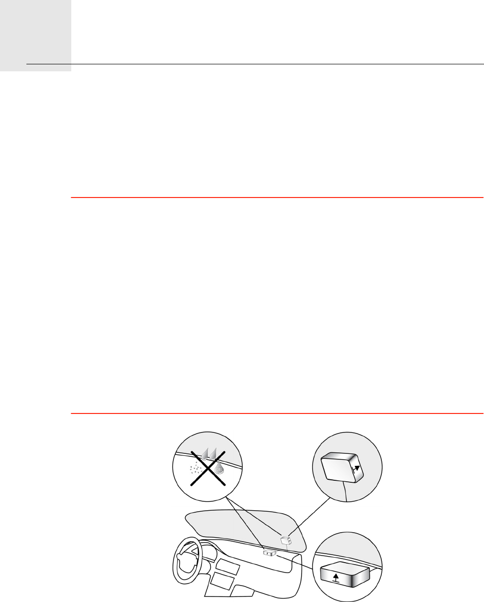
Find the right Place5.
6
Find
the
right
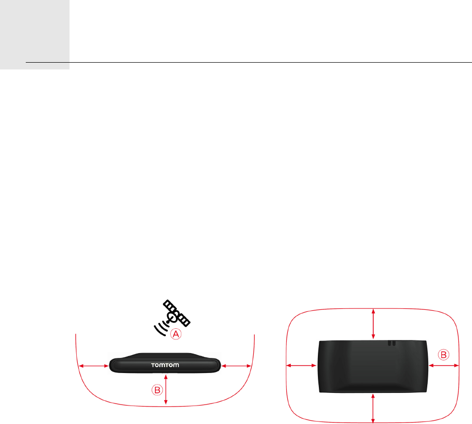
Place First you need to find the right place to install your LINK 510.
To find the right place take the following into consideration:
• Do not expose the LINK 510 to direct sunlight and/or high temperature for longer
periods to ensure proper operation.
• The top side of the device must not be obstructed by metal items to ensure GPS
reception using the integrated GPS receiver. For more felxibility with regards to
installation we recommend to use the external GPS antenna from TomTom Business
Solutions. For using the external GPS antenna, read Appendix: Using external
antennas on page 22.
• To ensure GSM/GPRS reception using the integrated GSM/GPRS antenna, the LINK 510
must not be placed on or surrounded by metal items such as the vehicle’s coachwork
closer than 5 cm and the top side must not be obstructed by metal items. For more
felxibility with regards to installation we recommend to use the external GSM antenna
from TomTom Business Solutions. For using the external GSM antenna, read
Appendix: Using external antennas on page 22.
ATop side of the LINK 510 must not be obstructed by metal items.
BKeep minimum distance of 5 cm to metal items.
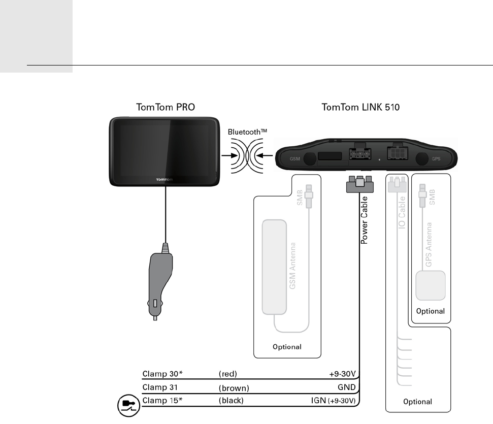
Connection overview6.
7
Con-
nec-
tion
over-
view
* Make sure this wire is fused with max. 10 A.
Connecting to power7.
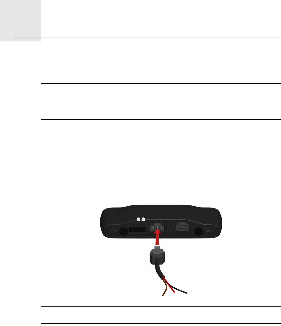
8
Con-
nect-
ing to
power Connect the LINK 510 to the vehicle power supply with the standard vehicle voltage (12 V
/ 24 V). Do not connect to a voltage converter. The three wires GND, IGN and PWR+
(supply voltage) must be connected.
Important: Follow the order of connecting the wires as described below. First connect the
wires then insert the plug into the LINK 510.
If you have inserted the plug into the LINK 510 first, you must connect the GND wire before
you connect the PWR+ wire and the IGN wire as described below.
1. Connect the GND wire (brown) to ground (clamp 31).
2. Connect the PWR+ wire (red) to the carry current (clamp 30).
The connection must be fused with max. 10 A. If not, fuse the the PWR+ wire with one
2 A fast blow fuse.
3. Connect the IGN wire (black) to ignition (clamp 15).
The connection must be fused with max. 10 A. If not, fuse the the IGN wire with one 2
A fast blow fuse.
4. Insert the 3-pin plug into the power cable connector.
If you need to disconnect the wires while the 3-pin plug is plugged in the LINK 510 make
sure you disconnect the GND wire at last.
9
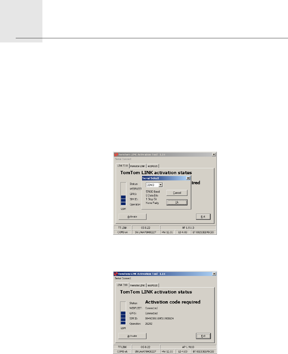
Activating LINK 5108.
10
Activat-
ing
LINK
510 After you have installed your LINK 510 in the vehicle activate the LINK 510 using the
TomTom LINK Activation Tool. You can also activate your LINK 510 using a TomTom PRO
navigation device, see Connecting to PRO and WEBFLEET on page 15.
1. Install the latest version of the TomTom LINK Activation Tool.
You can download the Activation Tool from the Partner Portal on our website https://
business.tomtom.com/10001/areas/reseller/index.xml. Go to Techinical Support and
select Activation and Diagnostics.
2. Connect your LINK 510 to your computer using the Mini USB cable.
3. Start the TomTom LINK Activation Tool by double clicking the icon.
4. Click Serial Connect and select the COM port to which you have connected your LINK
510.
5. Monitor the yellow connection LED on your LINK 510 until it indates the device has
established a connection to WEBFLEET, see Diagnostics on page 17.
When the connection to WEBFLEET is established the Activation Tool asks you to enter
your activation code.
6. Click Activate.
11
7. Enter the Activation Code, which you find in your WEBFLEET contract confirmation.
8. Click OK.
The progress of the activation and a successful activation are shown.
Mounting LINK 5109.
12
Mount-
ing
LINK
510 Your LINK 510 comes with an integrated GSM antenna and an integrated GPS antenna.
Depending on the place you choose for the installation, you can install your LINK 510
without external antennas.
To learn how to use external antennas with the LINK 510, see Appendix: Using external
antennas on page 22.
• The LINK 510 must be placed unobstructed by metal objects.
• The device must not interfere with clear vision for the driver.
• Tinted metallised windscreens or those with integrated filament heating may obstruct
GPS reception.
• Place the unit with min. 5 cm distance to the coachwork or other metal items, so that
optimal GSM transmission and GPS reception is ensured.
• The unit must be placed on an oil free, dry and clean surface, when using the adhesive
strips. Extreme temperature changes/differences can affect the adhesive property of
the strips.
• To find the right place read Safety first on page 4 and Find the right Place on page 6.
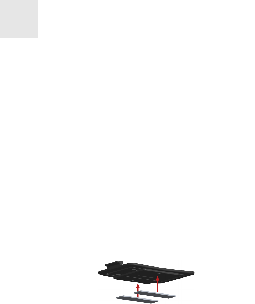
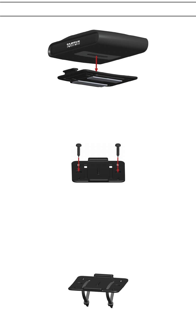
The LINK 510 can be affixed with the two adhesive strips, the two tapping screws or the
cable ties.
Attaching the holder using the adhesive strips
You can use the two adhesive strips to affix LINK 510 in the vehicle. Follow the safety
instructions in this document.
1. Choose a flat surface for accurate positioning of the unit.
Remember, when the LINK 510 is in the holder, it must not be obstructed by metal
objects.
2. Clean the surface with the provided cleaning tissue, so that the surface is oil free, dry
and clean.
3. Remove the protective film from one side of the strips.
4. Stick the strips to the bottom side of the holder.
5. Remove the protective films from the other side of both strips.
6. Place the holder with the adhesive strips on the prepared surface. Press it gently for a
few seconds until it sticks.
13
Note: The full strength of the strips will be reached after approx. 72 hours depending on
the temperature.
7. Insert the LINK 510 into the holder. Press gently until it clicks into place.
Attaching the holder using the self-tapping screws
You can use the two self-tapping screws to affix the holder in the vehicle.
1. Choose a flat surface for the LINK 510.
Remember, when the LINK 510 is in the holder, it must not be obstructed by metal
objects.
2. Insert the two screws into the corresponding holes in the holder.
3. Tighten the screws.
4. Carefully place the LINK 510 in the holder until it clicks into place.
Attaching the holder using the cable ties
You can use the two cable ties to affix the holder in the vehicle. Using cable ties might have
an impact on the accuracy of the driving event reporting if the device is not fixed properly.
1. Choose a place where the LINK 510 is obstructed by metal objects when it is in the
holder.
2. Insert the cable ties into the corresponding holes in the holder.
3. Wrap the cable ties around the object where you want to place the holder.
4. Pull the cable ties through the corresponding holes of the holder and insert them in the
in the noose at the other end of the cable ties.
5. Pull the cable ties tight so the holder cannot move.
6. Insert the LINK 510 into the holder. Press gently until it clicks into place.

Testing operation10.
14
Test-
ing op-
eration Apart from the tests described below you can test the operation of your LINK 510 using
the TomTom Business Solutions Diagnostic Tool via Bluetooth.
Power/Ignition test
Before testing the connection to power and to ignition make sure you have carried out the
steps described in the previous chapters.
1. Please check all connections to the LINK 510 (wires, fuses etc.).
2. Turn off the ignition. The green LED must be off and shortly on every 3 seconds.
3. Turn on the ignition. The green LED must be on and shortly off every 3 seconds.
If the LED does not perform accordingly see Diagnostics on page 17.
GPRS reception test
For this test, you may need to move the vehicle to a location with a clear view of the sky,
to make sure that you have adequate GPS and GPRS reception.
For this test put the LINK 510 into the place where you want to affix it (see Mounting LINK
510 on page 12).
1. Turn on the ignition.
2. Monitor the yellow LED. It must be on and shortly off every 3 seconds.
As soon as the device has established a connection to WEBFLEET the yellow LED stays
solid on.
If the LED keeps flashing longer than 10 min see Diagnostics on page 17.
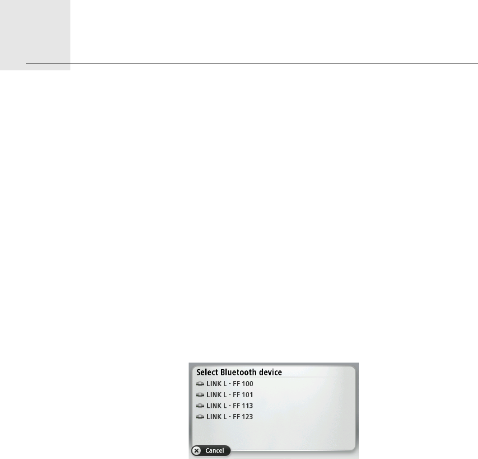
Connecting to PRO and WEBFLEET11.
15
Con-
nect-
ing to
PRO
and
WEB-
FLEET
Connect your navigation device to your LINK 510 to fully enjoy the benefits of your
WORKsmart solution.
To use a TomTom PRO navigation device in combination with the LINK 510 a
corresponding WEBFLEET subscription is required.
When you first switch on your navigation device, you are asked to connect it with the LINK
510 installed in your vehicle. You can do this immediately or at any time later.
1. Make sure that the LINK 510 is connected to power and has a GPRS connection.
2. Switch on your navigation device.
3. Tap the screen to bring up the Main Menu.
4. Tap WORK.
You are asked to start the activation process. After you have started the activation
process your navigation device starts searching for Bluetooth devices.
If your navigation device finds more than one Bluetooth device, it shows a list of the
available devices. Continue with step 5.
If your navigation device finds only one LINK 510, continue with step 6.
5. Select your LINK 510 from the list.
The name starts with LINK followed by the serial number of your LINK 510 or the license
plate number of your vehicle. You can find the serial number on the outside of your
LINK 510.
6. Enter the Activation Code, which you find in your WEBFLEET contract confirmation.
Select the appropriate subscription from the list, if there are several subscriptions to
choose from. Enter a name for your LINK 510 if you are asked to do so.
7. Enter the licence plate number of the vehicle.
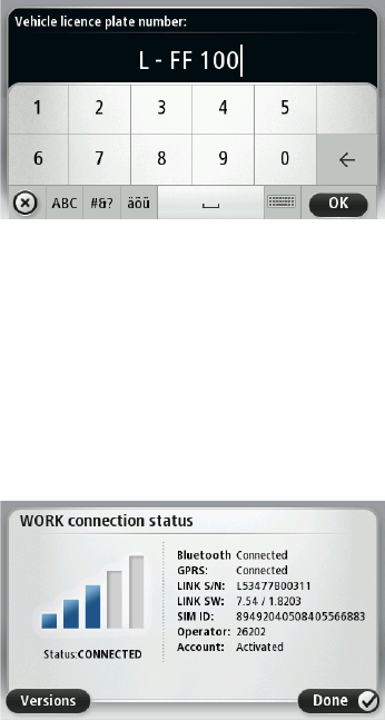
16
8. Select the appropriate vehicle type.
If you select Truck or Bus, you have to enter your vehicle dimensions
If you have properly connected the two devices, you will receive a welcome message from
WEBFLEET confirming the activation. In future the connection is established
automatically.
To check the connection status between the two devices, tap WORK in the main menu on
your navigation device, then tap Connection status.

Diagnostics12.
17
Diag-
nostics Monitoring operation
Monitor the system operation of LINK 510 through the green system LED according to the
table below.
For detailed diagnostics use the TomTom Business Solutions Diagnostic Tool. You can
download the Diagnostic Tool from the Partner Portal on our website https://
business.tomtom.com/10001/areas/reseller/index.xml. Go to Techinical Support and
select Activation and Diagnostics.
GREEN LED mode
OFF Unit is in standby mode or is not connected to
power.
• Switch on ignition.
• Check if the device is properly connected to
power, see Connecting to power on page 8.
OFF and shortly ON every 3sec Ignition off.
Rapidly flashing No operating system and/or no application
available or application failed.
• Install latest firmware application using the
TomTom Business Solutions Update Tool.
ON and shortly OFF every 3sec Ignition on. Application is running, device is not
activated.
• Activate device, see Activating LINK 510 on
page 10.
ON Application is running, device is activated.

18
Monitor the connection of the LINK 510 to the GSM network and to TomTom WEBFLEET
through the yellow connection LED according to the table below. For detailed diagnostics
always use the TomTom Business Solutions Diagnostics Tool.
Support
If you cannot find the answer to your question with the help of the tables above, please
contact the TomTom Business Solutions support team under https://
business.tomtom.com/support.
YELLOW LED mode
OFF Not connected - No GSM coverage.
• Check if device is connected to power, see
Connecting to power on page 8. Switch on
ignition.
•Leave dead spot.
OFF and shortly ON every 3sec Not connected - Correct GSM operator not
avaialable.
• Check WEBFLEET subscription for GSM
network roaming support.
•Leave dead spot.
Rapidly flashing SIM not in place; SIM defective; Modem
problem.
• Use TomTom Business Solutions Diagnostics
Tool for detailed diagnostics and contact
TomTom Business Solutions Customer
support under https://business.tomtom.com/
support. Enclose the log file provided by the
Diagnostics Tool.
ON and shortly OFF every 3sec Connecting. No GPRS available.
•Leave dead spot.
ON Connected.

Reset LINK 51013.
19
Reset
LINK
510 If the LINK 510 does not operate properly or signals a system error (see Diagnostics on
page 17) you may need to restart or reset the unit. Only restart or reset the LINK 510 after
you have made sure you have carried out all previously described steps without success.
Restarting your LINK
To restart your LINK 510 press the reset button with a thin pointed object until it clicks and
keep it pressed for 1 to 2 seconds. The LINK 510 restarts immediately after releasing the
button.
If restarting the device does not succeed remove the Power cable from the LINK 510. Then
plug it into the Power cable connector again.
Resetting your LINK to factory settings
To reset the LINK 510 to factory settings press the reset button with a thin pointed object
until it clicks and keep it pressed for 4 to 8 seconds. The LINK 510 reboots immediately
after releasing the reset button.
All information stored on the LINK 510 will be deleted.
If resetting the device does not succeed, do the following:
1. Remove the Power cable from the device.
2. Press the reset button with a thin pointed object until it clicks and keep it pressed.
3. Insert the Power cable while keeping the reset button pressed for 4 to 8 seconds.
You can count the seconds with the help of the flashing of the green LED, that flashes
once per second.
The LINK 510 reboots immediately after releasing the reset button.

Technical data14.
20
Techni-
cal data
Dimensions Body: 121 x 56.5 x 21.5 mm
Body with Holder: 121 x 68 x 25.5 mm
Weight Body: 88 g
Holder: 12 g
Material Body and holder: Injection moulded plastic PC/ABS
Protection class IP 20
Supply voltage 12 V / 24 V (min. 9 V to max. 30 V)
Current
consumption
(average values)
At 14 V: typically < 50 mA
At 28 V: typically < 30 mA
Standby: typically < 1 mA
During data transmission
14V < 180 mA
28V < 100 mA
Fuse protection Operating voltage* 9 - 30 V to be fused with max. 10 A
Ignition to be fused with max. 10 A
* Internally fused with 2 A, fuse is not resetable or replacable, fuse
must be replaced by TomTom Business Solutions only
Temperature Operation: -30 °C to +70 °C
Storage: -40 °C to +80 °C
GSM Integrated GSM antenna and GSM module
Dualband GSM 900/1800
GPS Integrated GPS antenna and GPS receiver
BluetoothTM Integrated BluetoothTM (class 2) for connection to navigation
device
Ignition input To be connected to the ignition clamp to switch on/off device
together with ignition
Digital inputs 2 inputs switchable to supply voltage
Digital output 1 input switchable to ground (open drain)
CANbus CAN H, CAN L
21
GPS antenna
connector for
external GPS
antenna
(optional
accessory)
SMB (male) - (antenna - female)
Supply voltage range 3.3 V
Minimum antenna gain at 3 V: 20 dB
Maximum antenna gain: 40 dB
Maximum noise rating: 1.5 dB
GSM antenna
connector for
external GSM
antenna
(optional
accessory)
SMB (male) - (antenna - female), for use with GSM antenna from
TomTom Business Solutions only
Appendix: Using external antennas15.
22
Appen
dix: Us-
ing ex-
ternal
anten-
nas Mounting external GPS antenna
If you install the LINK 510 in a place where it has poor GPS reception, you need to use the
external GPS antenna accessory from TomTom Business Solutions, Art. no 9UKE.001.00,
which comes with an integrated magnet and an adhesive pad. The external GPS antenna
from TomTom Business Solutions is not part of the standard LINK 510 product package.
To check if your LINK 510 has GPS reception see Diagnostics on page 17.
Important!
• Only use the GPS antenna from TomTom Business Solutions, else GPS performance
will be bad or not work at all.
• Tinted metallised windscreens or those with integrated filament heating may prevent
good GPS reception. In this case, place the GPS antenna in the rear window or on the
outside of the vehicle.
• The magnet of the antenna will remain attached to the outside of the car at speeds of
up to 180 km/h.
• Install the GPS antenna in a place where it has a clear view of the sky and is
unobstructed by metal objects.
• The GPS antenna must be placed with the adhesive pad on an oil free, dry and clean
surface.
• Extreme temperature changes / differences can affect the adhesive property of the pad.
1. Remove the rubber cap from the GPS antenna connector.
2. Insert the plug of the GPS antenna into the GPS antenna connector on the LINK 510.
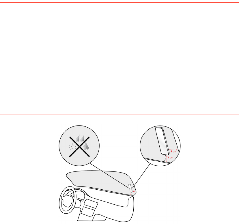
23
3. Prepare a smooth, clean, oil free and dry surface in the windscreen.
4. Attach the antenna to the prepared surface so that the top side has clear view of the sky.
Either locate a smooth metal surface or use the extra adhesive pad.
Mounting external GSM/GPRS antenna
If you install the LINK 510 in a place where it has poor GSM/GPRS reception, you need to
use the external GSM/GPRS antenna accessory from TomTom Business Solutions, Art.
no. 9KLE.001.03, which comes with an adhesive pad. The external GSM/GPRS antenna
from TomTom Business Solutions is not part of the standard LINK 510 product package.
To check if your LINK 510 has GSM/GPRS reception see Diagnostics on page 17.
Important!
• Only use the GSM/GPRS antenna from TomTom Business Solutions, else GSM/GPRS
performance will be bad or not work at all.
• Tinted metallised windscreens or those with integrated filament heating may prevent
good GSM/GPRS reception. In this case, place the GSM/GPRS antenna in the rear
window or on the outside of the vehicle.
• Install the GSM/GPRS antenna in a place where it is unobstructed by metal objects. The
GSM/GPRS antenna must be placed with minimum 5 cm distance to metal objects. The
top side of the GSM/GPRS antenna must not be obstructed by metal items.
• The GSM/GPRS antenna must be placed with the adhesive pad on an oil free, dry and
clean surface.
• Extreme temperature changes / differences can affect the adhesive property of the pad.
1. Remove the rubber cap from the GSM/GPRS antenna connector.
2. Insert the plug of the GSM/GPRS antenna into the GSM antenna connector on the LINK
510.
3. Prepare a smooth, clean, oil free and dry surface in the windscreen.
4. Attach the antenna to the prepared surface so that the top side has clear view of the sky.
Either locate a smooth metal surface or use the extra adhesive pad.
Appendix - Using the IO cable16.
24
Appen
dix -
Using
the IO
cable You can connect the IO cable from TomTom Business Solutions, Art. no. 9KLE.001.02, to
the IO cable connector of the TomTom LINK 510. With it you can read information from a
digital tachograph, record inputs e.g. for keeping digital logbook with the help of a switch,
reporting times the vehicle is idling, retrieving FMS/CANbus data etc.
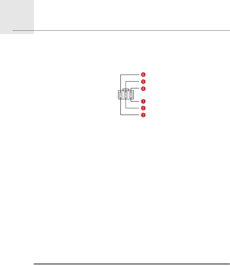
aCAN High (Orange/Black)
For FMS data retrieval.
bCAN Low (Orange/Brown)
For FMS data retrieval.
cGND (Brown)
dIN 1 (Blue/Green)
Digital input.
eIN 2 (Violet)
Digital input can be connected to digital tachograph or can be used for idling reporting
and logbook keeping.
fOUT (Green/White)
Digital output.
Connecting a digital tachograph
You can collect the time spent driving, resting and working from a digital tachograph by
connecting it to your LINK 510 via the digital input IN 2. Connect the input IN 2 to PIN D 8
of the digital tachograph.
Important!
Only authorised resellers are allowed to connect the LINK 510 to the digital tachograph.
Make sure that the ground potential of the LINK 510 is identical to the gound potential of
the digital tachograph.
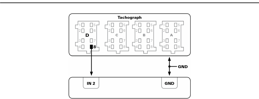
25
If the tachograph with the covered connectors is sealed, the seal must only be removed
by an authorised tachograph installer.
Using the input IN 2 for idle time reporting
LINK 510 can report idle times to WEBFLEET when the engine is running for longer than
five minutes and the vehicle is not moving. This requires configuration in TomTom
WEBFLEET.
The input IN 2 must be connected to a signal indicating the activity of the engine, e.g.
alternator, engine, etc. The input IN 1 must be active when the engine is running. For
detailed information on how to connect the relevant signal to IN 2, see Wiring digital
inputs on page 25.
Using the input IN 2 for changing the logbook mode
LINK 510 can report logbook relevant information to WEBFLEET. Using the input IN 2 you
can change the logbook mode between private and business trips. This requires
configuration in TomTom WEBFLEET.
The input IN 2 must be connected to a switch indicating the trip mode. If the input IN 2 is
active the logbook mode is set to Private trip. If no or a low voltage applies to the input IN
2 the logbook mode is set to Business trip. For detailed information on how to connect IN
2, see Wiring digital inputs on page 25.
Wiring digital inputs
The digital inputs of the LINK 510 operate according to the principle of a voltage detector.
Voltages below 2 Volts are definitively interpreted as being low and voltages higher than
3 Volts are definitively interpreted as being high. The maximum permissible input voltage
is 30 Volts. Low/high switching (increasing input voltage) typically occurs at 2.8 Volts.
High/low switching (decreasing input voltage) typically occurs at 2.1 Volts. The hysteresis
of 0.7 Volts is to avoid rapid switching.
Interference voltages at the digital inputs must remain below 2 Volts. In order to guarantee
this, the input wire of the connecting cable should never remain unconnected. If a digital
input is not being used, the input wire must be connected to ground (GND). To evaluate a
switch, this switch needs to be designed as a change-over switch, switching the digital
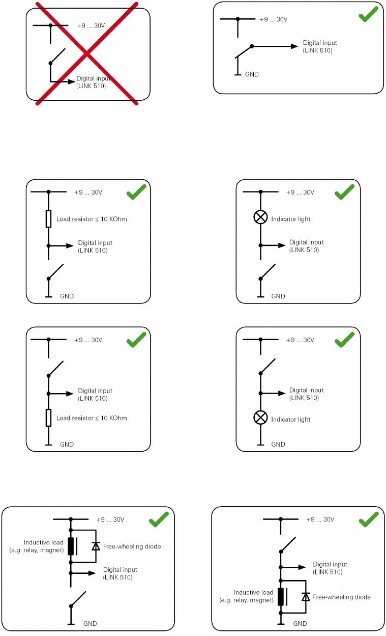
26
input between plus and minus (ground GND) of the vehicle electrical system voltage (+9
... 30V).
If no change-over switch is available, an electric load (e.g. indicator light, resistor) between
the digital input and ground (GND) or between the digital input and the vehicle voltage (+9
... 30V) can offer defined levels.
When using inductive loads, a free-wheeling diode must be used in parallel with the load.
27
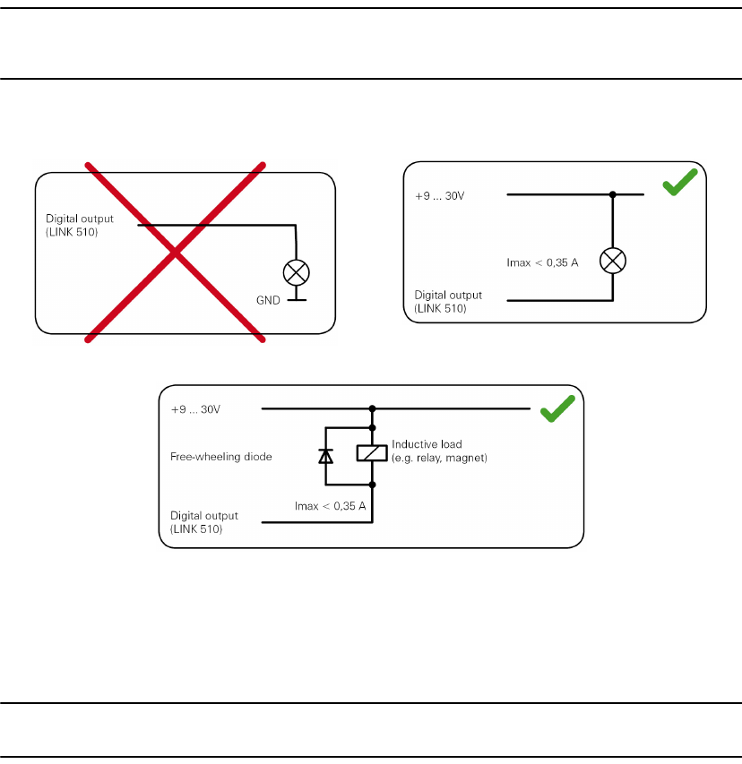
Wiring the digital output
The digital output OUT of the LINK 510 is an open drain output linking to ground. The
connected load must be connected between vehicle voltage and OUT. Loads requiring
more than 0.35 A must be controlled with relays. If the load requires more than the
maximum output voltage use a 12 V/24 V relay, depending on the operating voltage.
Caution
Do not switch safety relevant vehicle functions.
Accessing FMS data
With the TomTom LINK 510 and the IO cable from TomTom Business Solutions you
access the FMS interface of your vehicle. Connect the CAN H and the CAN L wires of the
IO cable to the CAN H and the CAN L pins of the FMS connector in your vehicle.
Make sure you have linked the GND wire of the IO cable from TomTom Business Solutions
to ground.
Addendum17.
28
Adden-
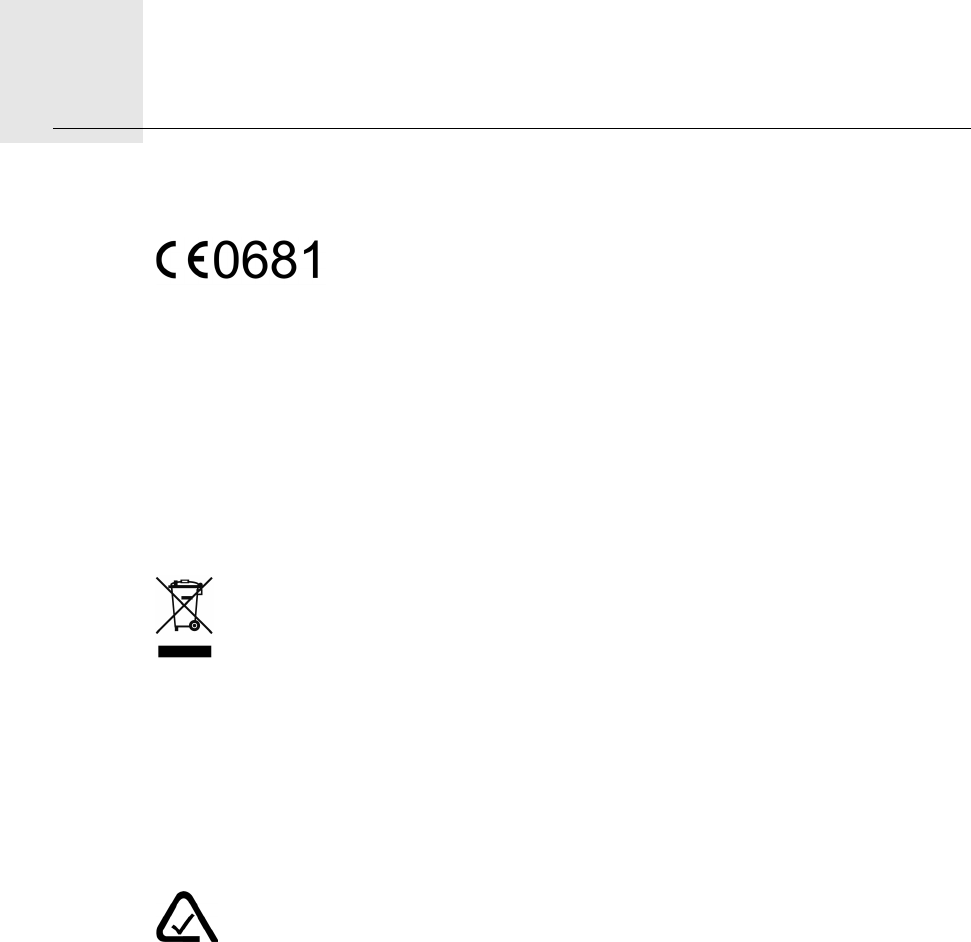
dum CE-Declaration of Conformity
The unit described in this document is in accordance with the official
European directives. A copy of the declaration of conformity can be
provided on request. This equipment complies with the essential
requirements of EU Directive 99/5/EC. The GPRS-modem integrated in this product has
been pre-certified separately and is marked with CE0681.
FCC-ID:S4LLINK500
This device complies with Part 15 of the FCC Rules. Operation is subject to the following
two conditions: (1) this device may not cause harmful interference, and (2) this device
must accept any interference received, including interference that may cause undesired
operation.
WEEE Directive
In line with EU Directive 2002/96/EC for waste electrical and electronic equipment
(WEEE), this electrical product must not be disposed of as unsorted municipal
waste. Please dispose of this product by returning it to the point of sale or to your
local municipal collection point for recycling.
Exposure limits
This device complies with radiation exposure limits set forth for an uncontrolled
environment. In order to avoid the possibility of exceeding the radio frequency exposure
limits, human proximity to the antenna shall not be less than 20cm (8 inches) during
normal operation.
A-tick
N14644
The TomTom LINK 510 product displays the A-tick to show it complies with
relevant Australian regulations.
Warning for Australia
The user needs to switch off the device when exposed to areas with potentially explosive
atmospheres such as petrol stations, chemical storage depots and blasting operations.
Customer Support contact
Australia: 1300135 604
Legal Information
©2011 TomTom N.V., The Netherlands. TomTom®, The “two hands”® logo, among
others, are Trademarks owsened by TomTom N.V. or one of its subsidiaries. Our End User
29
License Agreement and limited warranty apply to this product. You can review it at
www.tomtom.com/legal