Tong Lung Metal Industry PL2-ZW TOUCHPAD ELECTRONIC DEADBOLT LOCK User Manual Manual
Tong Lung Metal Industry Co.,Ltd. TOUCHPAD ELECTRONIC DEADBOLT LOCK Manual
Manual
123
456
789
0
USER MANUAL
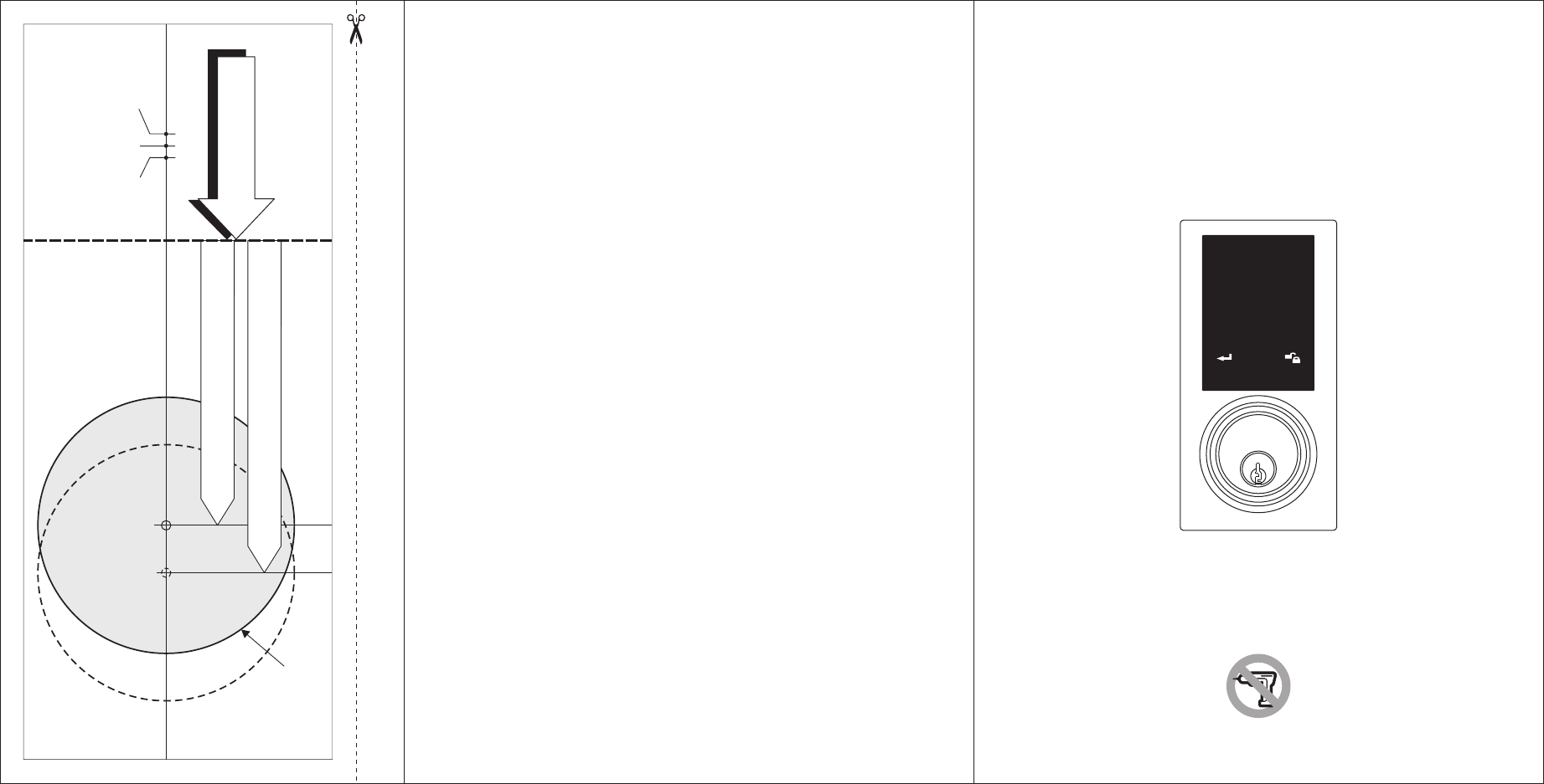
TEMPLATE
45 40 35
1-3/4" 1-9/16" 1-3/8"
Fit here on door edge
FOR BACKSET 70mm (2-3/4”)
FOR BACKSET 60mm (2-3/8”)
Mark Ø1" (25.4mm) hole at
center of door edge.
Ø54mm (2-1/8")
Attention : Please do not use the "electronic" screwdriver for installation.
Product :
Purchase Date :
Limited Warranty Statements
1. Warranty
The manufacturer warrants the Product to be free
from defects in material and workmanship for a period of 12 months
from the original date of purchase.
If you discover a defect in the Product covered by this warranty, we will repair or
replace the item at our option using new or refurbished components.
2. Exclusions
This warranty covers defects in manufacturing discovered while using the
Products as recommended by The manufacturer rather than occurred by the act
of God, and damages caused by misuse, abuse, and unauthorized modification.
3. Limited of Liability
The manufacturer will not be held liable for incidental or consequential losses or
damages to any act of God.
4. Reminder
Service requirement shall subject to the presentation of this warranty card
and defective parts to the manufacturer.
The warranty card will not be reissued if lost.
TOUCHPAD
ELECTRONIC DEADBOLT LOCK
1
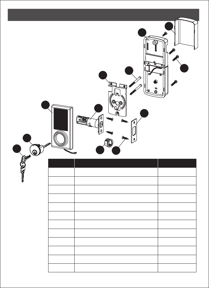
PACKAGE CONTENTS
A
B
CDE
F
G
H
I
L
K
J
PART DESCRIPTION QUANTITY
A
B
C
D
E
F
G
H
I
J
K
L
Key
Cylinder
Deadbolt pad AssemblyTouch
Deadbolt Latch
Strike Plate
Mounting Plate
Receiver Assembly
Battery Cover
Drive-in Sleeve
2
1
1
1
1
1
1
1
1
3
5
2
Machine Screws
Wood Screws
Deadbolt Chassis Screws
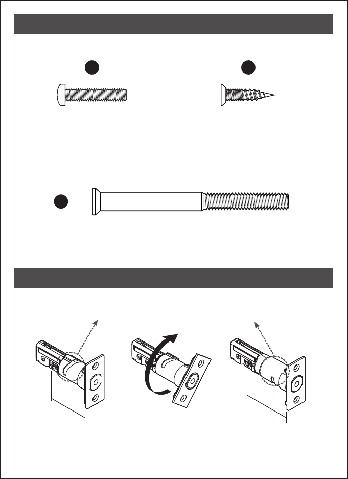
2
Machine Screws
Qty. 3
Wood Screws
Qty. 5
Deadbolt Chassis Screws Qty. 2
J K
L
HARDWARE SCREWS CONTENTS
LATCH BACKSET ADJUSTMENT
Remarks:
Please notice the the latch box between two different backsets.slight differences in
180°
2 3/4" (70 mm)2 3/8" (60 mm)
70 mm
60 mm
3
1
2
2.1
1. Backset Determination
Backset is a distance from door edge to
centre of hole on door face.
Adjustable latch fits both backset of
2 3/8" (60 mm) and 2 3/4" (70 mm).
2. Change Latch Face
Determine which latch mounting method will
be used and make necessary adjustments.
No adjustment required for square latch
face plate.
a. Use a flat screwdriver to separate the
face plate.
b. Snap selected latch face plate onto back
plate.
Drive-in Latch
Drive-in Installation
Remove original latch faceplate.
Align the (I) as illustrated and
snap into the latch case.
drive-in sleeve
a
b
D
D
I
ASSEMBLY INSTRUCTIONS
4
3
4
5
2 3/4" (70 mm)
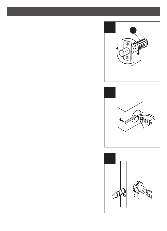
3. Latch Backset Adjustment
Determine if the latch (D) needs to be adjusted
to the 2 3/4" (70 mm) backset.
To adjust, rotate the latch until it stops.
Reverse the direction to return to the
2 3/8" (60 mm) backset.
4. Mark the Door with Template
Select the height and backset as desired on
the door face; use the TEMPLATE as an
indication to mark the centre of the circle on
the door face and the centre of the door
edge.
5. Drill Holes
Using the marks as a guide to drill a hole
Ø2 1/8" (54 mm) through the door face for
the lockset, then a hole of Ø1" (25.4 mm)
for latch.
D
ASSEMBLY INSTRUCTIONS
5
6
7
8
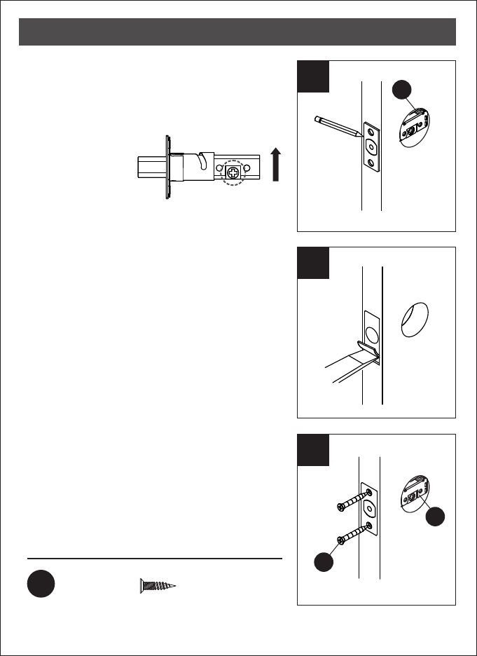
6. Mark the Outline of Latch Faceplate
Insert the latch (D) and ensure it is parallel to
the door face.
Mark the outline of the faceplate, then
take out the latch (D).
7. Chisel Space for Latch Faceplate
Chisel 5/32" (4 mm) deep along the outline
to allow the faceplate to be aligned with
the door edge.
Note: It is not necessary to chisel the door
edge for the faceplate installation if
you use the drive-in latch.
8. Install Latch
Insert the latch (D) into the door.
(Make sure the cross is on the bottom of the
latch.) Use 2 wood screws (K) to secure latch.
Please do not fully tighten the screws until
lock is completely installed.
Hardware Used
KWood screws x2
D
D
K
ASSEMBLY INSTRUCTIONS
You need to stay
this way up when
inserting the latch.
Make sure the cross in the
latch is on the bottom.
6
8.1
9
10
Install Drive-in Latch
Drive the latch (D) into the hole on edge of
door.
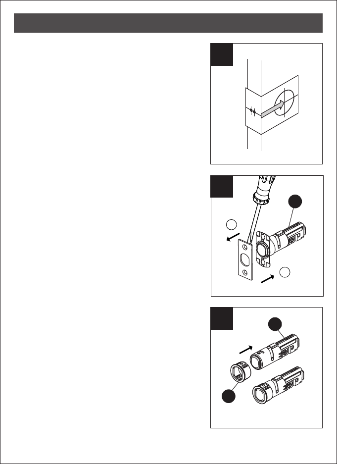
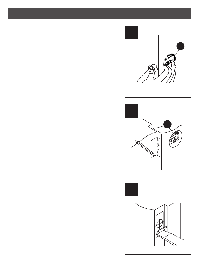
9. Mark the Outline of Strike
To identify the centre of strike: close the
door to lay the latchbolt against the door
frame. Mark the centre line on the doorframe
exactly opposite the latch hole in the door
edge.
10.1 Drill Hole on Door Frame
Measure one half of door thickness from door
stop and vertically mark centre line of strike.
Drill 1" (25.4 mm) hole, 1" (25.4 mm)
deep at intersection of horizontal and vertical
line of strike.
10.2 Chisel Space for Strike
Chisel 5/64" (2 mm) deep along the strike
outline to allow the strike to be aligned with
the doorframe.
D
D
ASSEMBLY INSTRUCTIONS
7
11
12
13
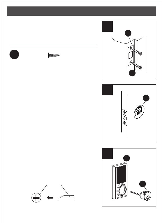
11. Install Strike on Door Frame
Install the strike plate (E) into your door frame
and tighten with wood screws (K).
12. Install Touchpad Assembly
Make sure the latch bolt is retracted.
13. Install AssemblyTouchpad
touchpadInstall cylinder (B) into the deadbolt
assembly (C) with tailpiece in horizontal
position inserted through hub of the latch.
E
K
D
ASSEMBLY INSTRUCTIONS
B
Hardware Used
KWood screws x2
horizontal position
C
C
Left-handed Right-handed
Hardware Used
8
LDeadbolt chassis screws x2
15
16
14. Install Assembly
Pass the IC wire under the latch (D) to the
interior side of the door, and insert the
tailpiece through the cross-shaped crank
of the latch
Touchpad
.
15. Install Inside Mounting Plate
Pass the IC wire through the wire hole of the
mounting plate (F). Fix the mounting plate (F)
with screws (L). If outside lock assembly is
lopsided, please loosen the screws to adjust
its position and tighten the screws again.
16. Identify Door Handing
Face the door from the outside. The
door is left-handed if the hinges are
on the left side of the door, whereas
the door is right-handed if the hinges
are on the right side of the door.
L
F
ASSEMBLY INSTRUCTIONS
Hinge Hinge
horizontal position
14
D
C
B
IC wire
Hardware Used
9
17
18
19
For right-handed
door
For left-handed
door
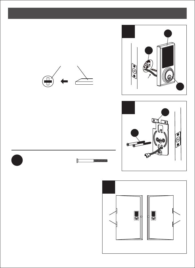
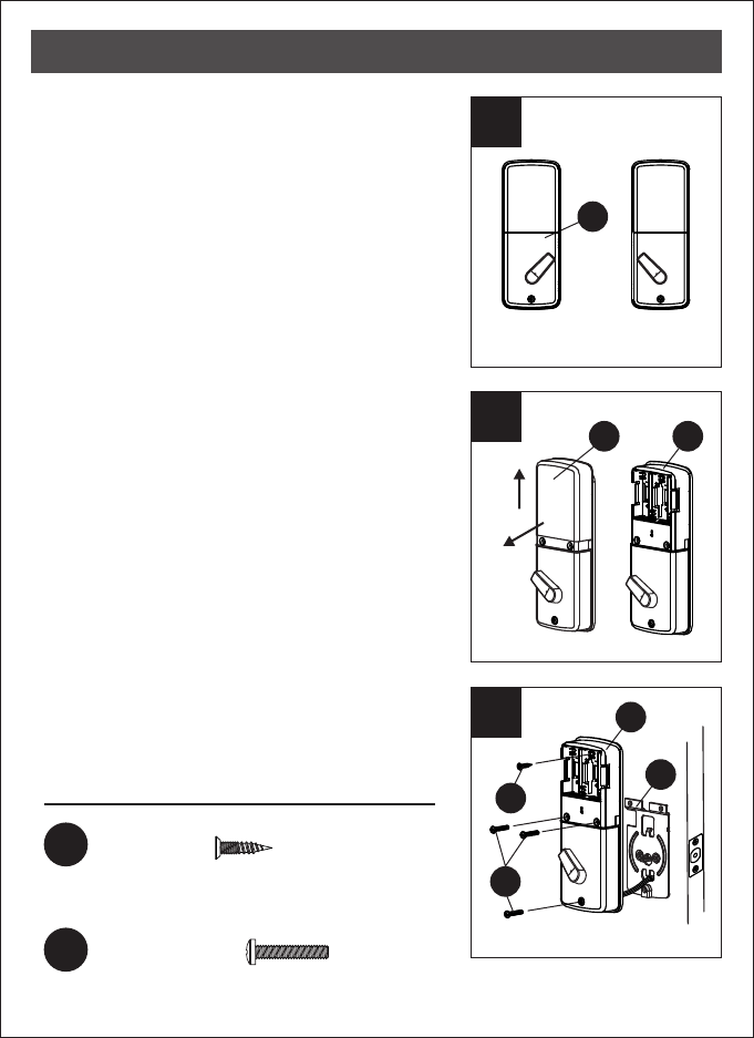
17. Adjust Thumb Turn Piece
Rotate the thumb turn piece to the LEFT at
45 degrees for right-handed doors.
Rotate the thumb turn piece to the RIGHT at
45 degrees for left-handed doors.
18. Install Receiver Module
Remove the battery cover (H)
(push it up first then pull it out).
19. Install Receiver Module
Connect the IC wire into the back of the
receiver module. Ensure that the deadbolt
tailpiece is engaged with turn piece, then
attach receiver module (G) to the door with
screw (J). Use the optional wood screw (K)
to secure the receiver module to wood doors
only.
JMachine screws x3
G
H G
G
F
K
J
ASSEMBLY INSTRUCTIONS
KWood screw x1
This screw is optional. It may not be necessary to
use this screw.
20
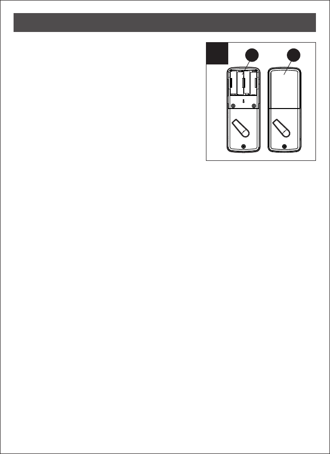
20. Insert Batteries
Insert 4 (AA) 1.5 V alkaline batteries and
slide the battery cover (H) back onto the
receiver module (G).
Remarks:
(1) Alkaline batteries are recommended in
order to stabilize the power supply. If you
don't use alkaline, battery performance
will be reduced greatly.
(2) All settings will be retained in the memory
even if the batteries are completed dead.
10
G H
ASSEMBLY INSTRUCTIONS
123
456
789
0
11
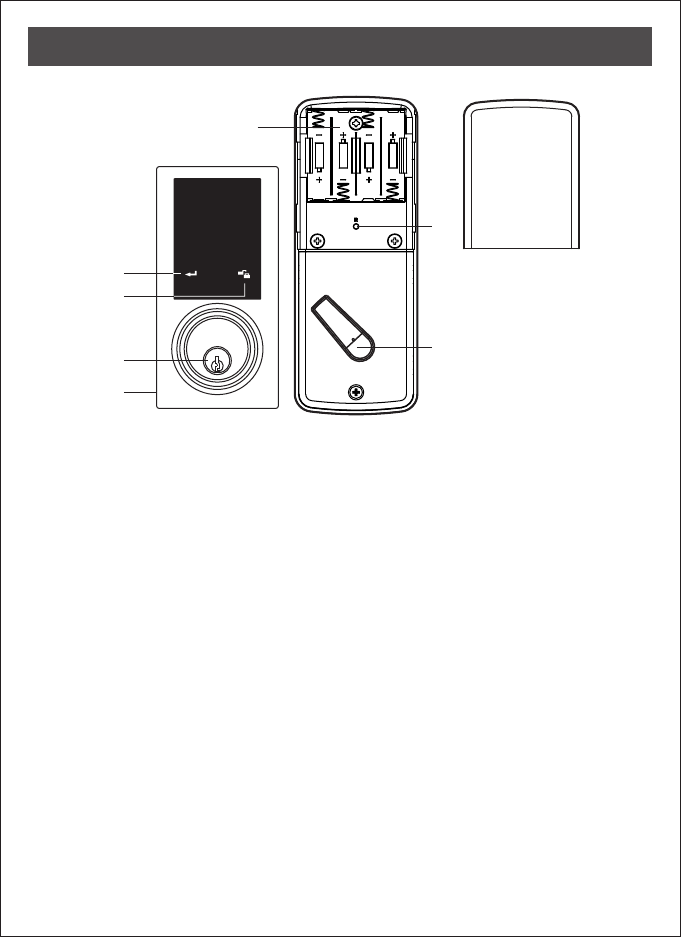
Programming Button
Programming button is for setting function.
.
Cylinder
To lock/unlock the lockset from outside.
Washer
Prevents water from permeating into lockset.
Battery Lid
Slide the lid to change the batteries.
Battery Holder
Four AA (1.5 V) alkaline batteries.
R Button (Reset)
Restore default settings.
Turn-piece
To lock/unlock the lockset from inside.
Lock Btutton
Lock Button is for lock and unlock function
by key
OPERATIONAL INTERFACE
12
Keep the door open while programming to avoid being locked out
accidentally. The lock contains one factory-preset user code but can be
programmed to store up to a total of six additional unique user codes.
˙Codes can be added and deleted at any time. For first-time programming,
use factory default programming code. It’s recommended to change the
default programming code and default user code right after you install
the lock.
˙
Every programming step should be done within 6 seconds.
OPERATING INSTRUCTIONS
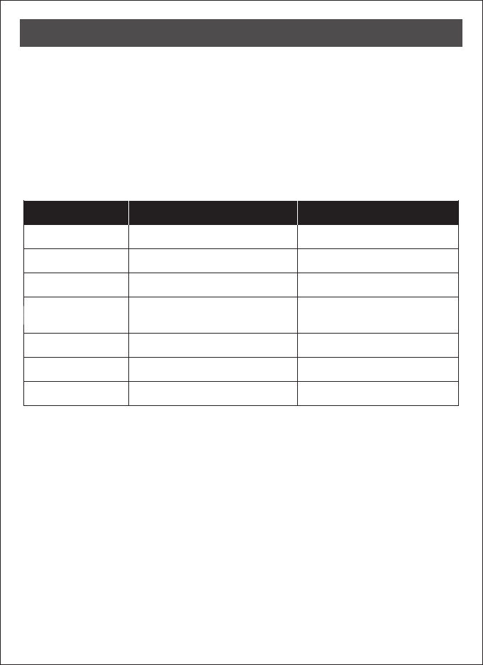
Operation Indicator Sounds and Lights
Sounds Lights Meaning
Successful Operation
Successful Programming
Operation Error
Code Input Error;
System Shuts Down
Low Battery Power
Default Setting Restored
In Programming Mode
1 Beep
2 Long Beeps
3 Beeps
5 Beeps
10 Rapid Beeps
Lock button flashes slowly
3 Long Beeps
3. Add New User Code
Note:
4–10 digits in length.
Up to 30 sets of user codes can be saved. User codes should be
13
OPERATING INSTRUCTIONS
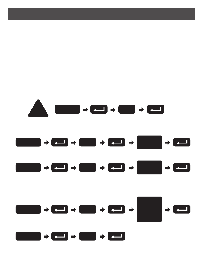
2. Change Programming Code
4. Delete an Existing User Code
5. Delete All User Codes at Once
Note:
user codes are deleted.
The lock can only be operated by key during that time.
Auto-locking and keypad locking functions will be invalid when
Default programming code (PC): 0000
Default user code (UC): 1234
Your new programming code (PC) ____________
Your new user code (UC) ___________________
The same programming code and user code cannot be accepted.
The lock will cease operation if unauthorized codes are entered
over 5 times. The system will unfreeze after 45 seconds.
DO THIS FIRST
1. Door Handling Identification Process
The lock needs to learn if your door is a right- or left-handed .
!0
Enter PC
4
Enter PC Enter
New PC
1
Enter PC Enter
New UC
2
Enter PC
Enter
the UC you
want to
delete
3
Enter PC
14
OPERATING INSTRUCTIONS
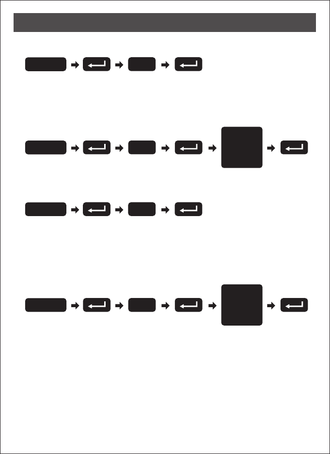
8. Enable/Disable All User Codes
Note:
user codes are disabled. The lock can only be operated by key
during the time. Repeat the steps to enable the user codes again.
Auto-locking and keypad locking functions will be invalid when
9. Create a One-Time User Code 4–10 Digits Long
Note: The one-time user code will automatically cancel after it is used
one time.
6. Toggle Auto-Lock On/Off
Note:
following instructions #7.
Repeat the steps in #6 to cancel the auto-locking function.
The preset delay-time is 30 seconds, you can change the time by
7. Set Auto-Lock Time Delay
Note: 10–99 seconds delay-time available.
5
Enter PC
6
Enter PC
Enter
Seconds
(10~99)
7
Enter PC
8
Enter PC
Enter
One Time
Code
OPERATING INSTRUCTIONS
15
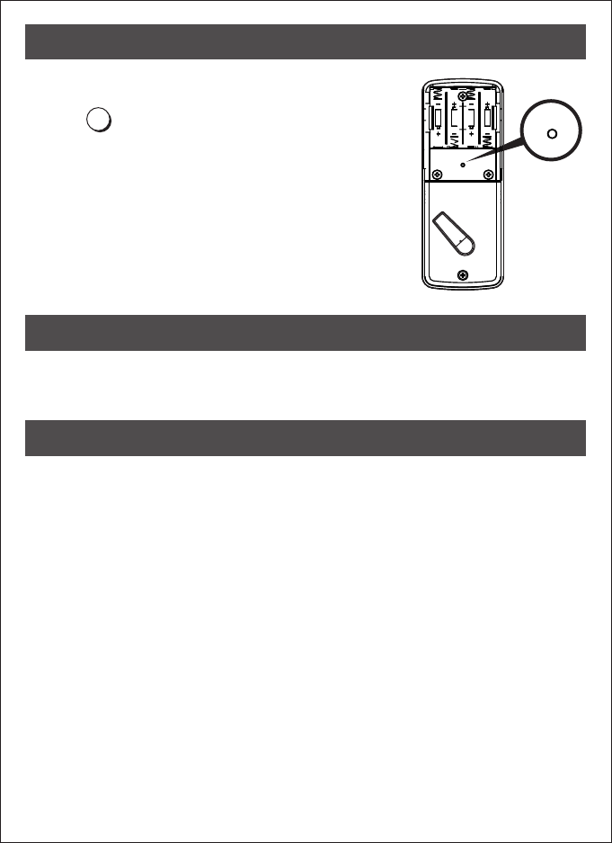
10. Restore Default Settings
Press R
Note: Press the button for more than 5 seconds;
the programming is reset back to the original
factory codes once you hear 3 long beeps.
After restoring default settings, you must run
the door handing identifying process (#1)
again before programming any other
functions.
R
Reset
button
WARRANTY
CARE AND MAINTENANCE
Do not use any chemical liquid or lubricating oil with additives to clean the
lock body. It will damage the surface or even mainboard.
The manufacturer warrants the product to be free from defects in material
and workmanship for a period of 12 months from the original date of
purchase. If you discover a defect in the product covered by this warranty,
we will repair or replace the item at our option using new or refurbished
components.
EXCLUSIONS
This warranty covers defects in manufacturing discovered while using the
products as recommended by the manufacturer rather than occurred by
the act of God, and damages caused by misuse, abuse, and unauthorized
modification.
LIMITED LIABILITY
The manufacturer will not be held liable for incidental or consequential
losses or damages from any act of God.
R

16
After installing the lockset
and batteries, the door
can’t be locked and three
short beeps are emitted
when you press the
lock button.
The door-handing
identification process
isn’t yet complete.
Refer to step1, page13.
You’ve installed the
lockset and batteries, but
you still get no response
when you press any
button.
Batteries were installed
incorrectly and cable
connect incorrectly.
Check to see if the battery
polarities have been
reversed or if the battery is
dead. If so, re-install or
change the battery. If not,
please check to see if the
cable is properly
connected.
When you are in the
door-handing identifying
process, you hear three
times, and three short
beeps.
Wrong door-handing or
change of the
door-handing in the
memory.
Press the R button to
restore the system to
factory default setting and
re-execute door-handing
identifying process
(step 1, page 13)
Although you succeeded
in the first execution of
the door-handing
identifying process, the
latch still doesn’t work.
(i.e. You can feel the motor
attempting to run.)
Low battery. Replace with new alkaline
batteries.
PROBLEM POSSIBLE CAUSE CORRECTIVE ACTION
TROUBLESHOOTING

17
The door can be locked
normally, but when you try to
unlock it, you hear three short
beeps and the lock won't
unlock when you enter the
user code and press the
lock button.
The functioning of the
micro-switch is abnormal.
Call our customer
service department
While the door is locked, you
hear the latch bolt coming out
when you press the
lock button to lock the door;
however, three short beeps
are emitted.
Conversely, while the door is
open, no beeps are emitted
when locking the latch bolt.
(1) The depth of the latch
bolt hole is insufficient.
(2) The latch bolt is not
aimed at the opening
of the strike.
(1) Dig the latch bolt hole
for the strike
(2) Adjust the strike to the
appropriate position.
deeper.
The minimum depth is
1" (2.5 cm).
PROBLEM POSSIBLE CAUSE CORRECTIVE ACTION
TROUBLESHOOTING
.
正面148x105mm ( )
背面148x105mm ( )
•
•
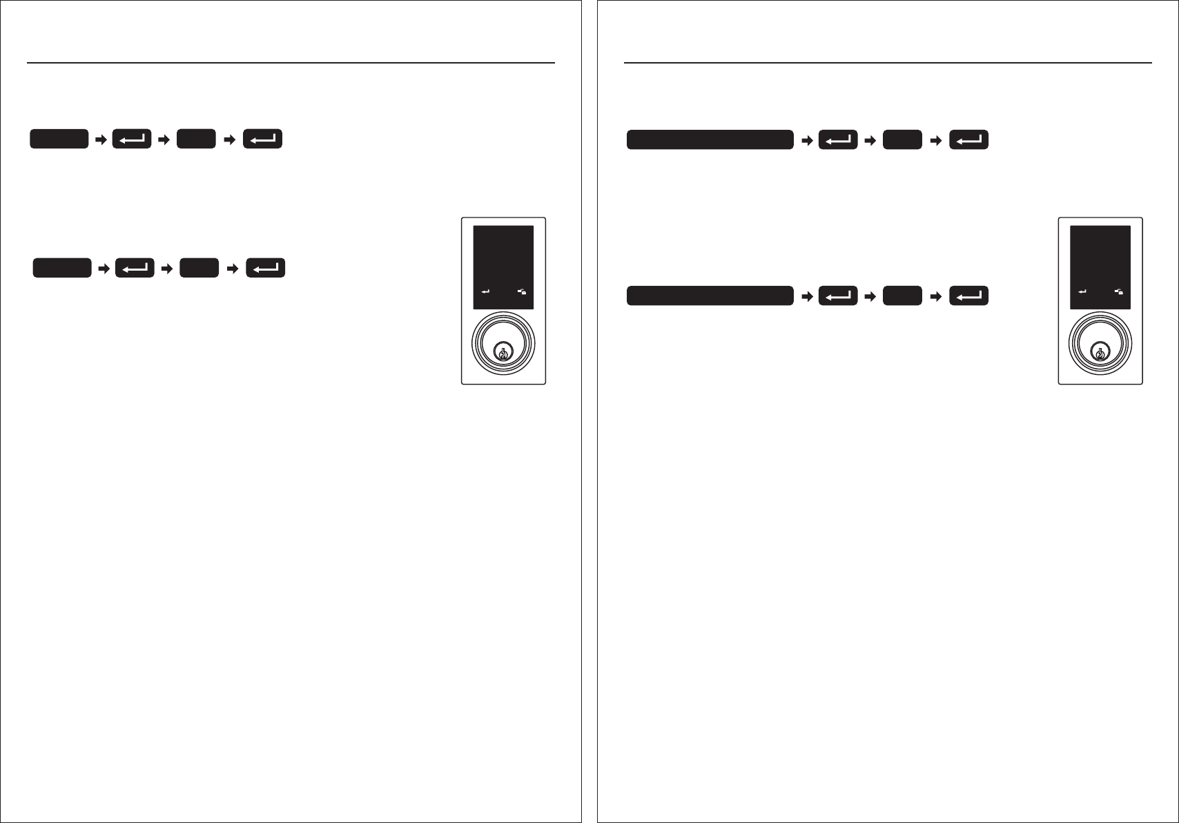
Añadir la cerradura a su pasarela Z-Wave
→
→Si escucha 2 pitidos la programación de su cerradura fue exitosa. Si escucha
5 pitidos debe iniciar el proceso nuevamente ya que la programación no se completó
adecuadamente.
Eliminar la cerradura de su pasarela Z-Wave
→Presione eliminar dispositivo en su aplicación, luego siga estos
pasos en su cerradura.
→Si escucha 5 pitidos debe iniciar el proceso nuevamente ya que
la eliminación no fue exitosa.
Presione añadir dispositivo en su aplicación, luego siga estos pasos en su cerradura.
then back to lock.Tap add device on your app, then back to lock.
Añadir/Eliminar cerradura
123
456
789
0
9
Ingresar código de programación
9
Ingresar código de programación
Cumplimiento de normas
Este producto cumple con los estándares establecidos por los siguientes entes reguladores:
Federal Communications (FCC)
Industry Canada
FCC
Este dispositivo cumple con la sección 15 de las reglas de la FCC. La operación está sujeta a las siguientes dos condiciones:
(1)Este dispositivo no ha de causar interferencias dañinas, y (2) este dispositivo debe aceptar cualquier interferencia recibida, incluyendo una
interferencia que podría causar una operación no deseada.
Este equipo se ha sometido a pruebas y cumplió con los estándares de un dispositivo digital Clase B, en referencia a la sección 15 de las reglas
de la FCC.
Estos estándares están diseñados de tal forma que provean una protección razonable en contra de interferencia dañina en una instalación residencial.
Este equipo genera, utiliza y podría irradiar energía de frecuencia de radio y, de no instalarse y utilizarse según las instrucciones, podría causar
interferencia dañina a sus comunicaciones de radio.
Sin embargo, no hay garantía de que la interferencia no ocurrirá en una instalación en particular.
Si este equipo llegara a causar interferencia dañina a su recepción de radio o televisión, lo cual se podría al encender o apagar todo el
, se aconseja que corrija la interferencia tomando una o más de las siguientes medidas:
Traslade a un Nuevo lugar su antena.
Aumente la separación entre su equipo y el receptor.
Conecte el equipo a un enchufe con un circuito distinto al cual está conectado actualmente.
Consulte a su vendedor o a un técnico con experiencia de radio/televisión para ayuda adicional.
Importante
Cambios o modificaciones hechas al equipo sin autorización escrita por el manufacturero podría invalidar la autoridad del usuario a operarlo.
•
•
determinar
equipo
•
•
•
•
Commission
英文版 正面148x210mm- ( ) -西文版 背面148x210mm ( )
REGULATORY COMPLIANCE
This product complies with standards established by the following regulatory bodies:
• Federal Communications Commission (FCC)
• Industry Canada
FCC
This device complies with Part 15 of the FCC Rules. Operation is subject to the following two conditions:
( 1 ) this device may not cause harmful interference, and ( 2 ) this device must accept any interference received, including interference
that may cause undesired operation.
This equipment has been tested and found to comply with the limits for a Class B digital device, pursuant to Part 15 of the FCC Rules.
These limits are designed to provide reasonable protection against harmful interference in a residential installation.
This equipment generates, uses, and can radiate radio frequency energy and, if not installed and used in accordance
with the instructions, may cause harmful interference to radio communications.
However, there is no guarantee that interference will not occur in a particular installation.
If this equipment does cause harmful interference to radio or television reception, which can be determined by turning the equipment off and on,
the user is encouraged to try to correct the interference by one or more of the following measures:
• Reorient or relocate the receiving antenna.
• Increase the separation between the equipment and receiver.
• Connect the equipment into an outlet on a circuit different from that to which the receiver is connected.
• Consult the dealer or an experienced radio/TV technician for help.
IMPORTANT !
Changes or modifications not expressly approved by the manufacturer could void the user' authority to operate the equipment.
• Adding lock to your Z-Wave gateway
If you hear 2 beeps from your lock the programming was successful. If you hear 5
beeps from your lock you must start over again (the programming failed).
• Removing lock from your Z-Wave gateway
If you hear 5 beeps from your lock you must start over again
(the programming failed).
→
→
→Tap add device on your app, then back to lock.
→
Tab add device on your app, then back to lock.
then back to lock.Tap add device on your app, then back to lock.
Adding/Removing lock
123
456
789
0
9
Enter PC
9
Enter PC
PL2S-Zwave PL2S-Zwave