Tong Lung Metal Industry PL2-ZW1 TOUCHPAD ELECTRONIC DEADBOLT LOCK User Manual Manual

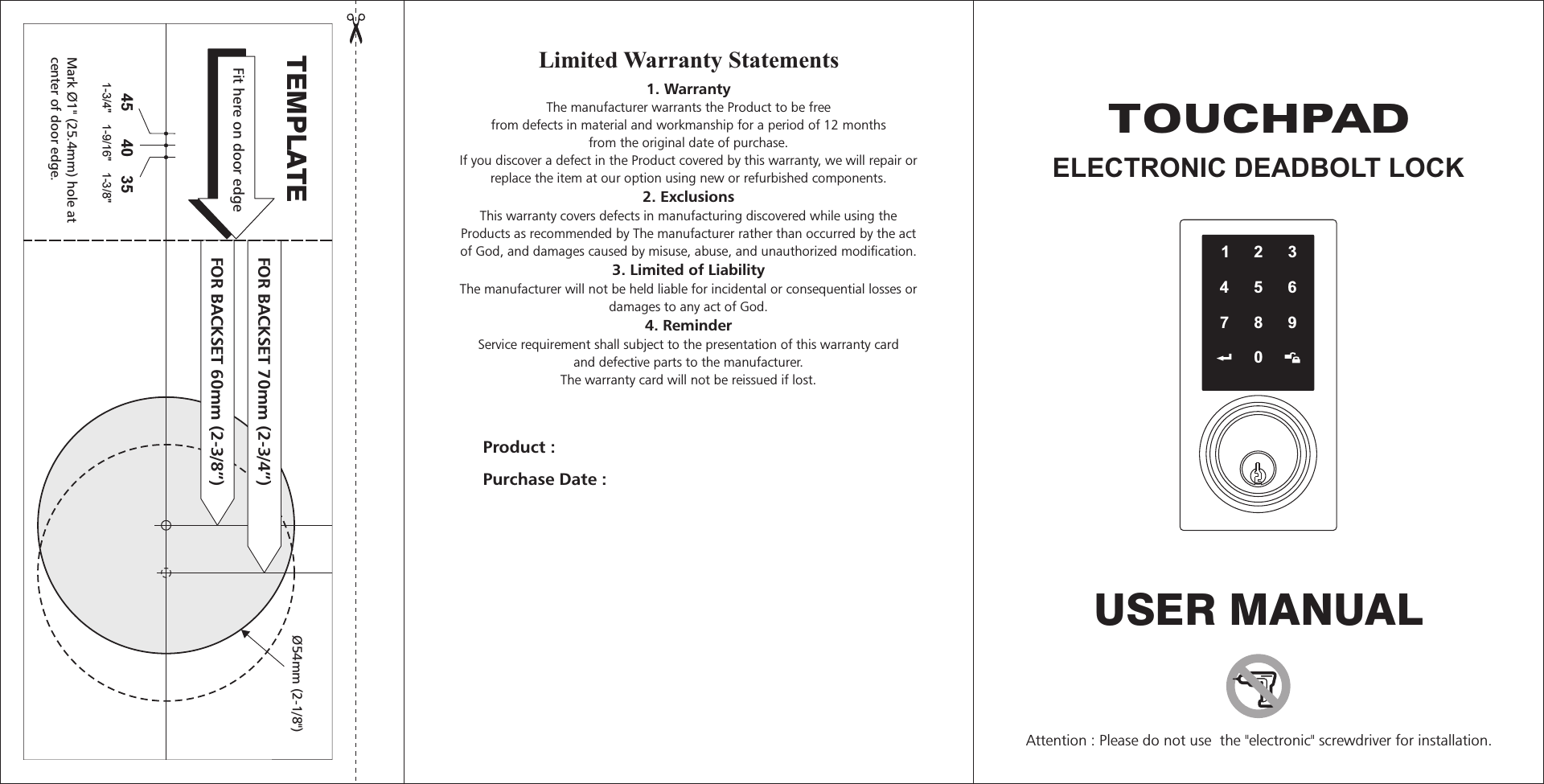
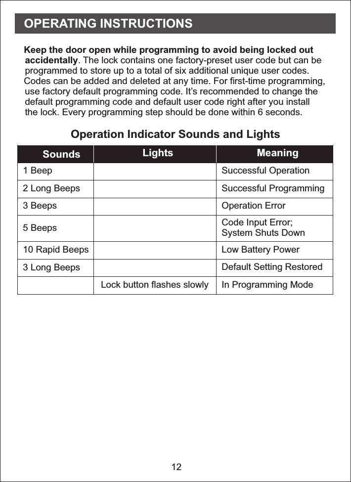
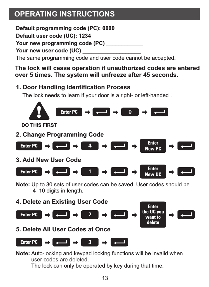
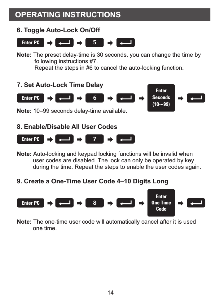
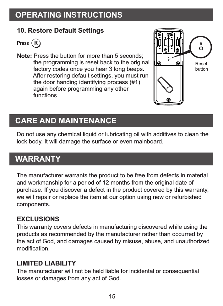
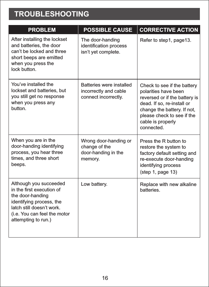
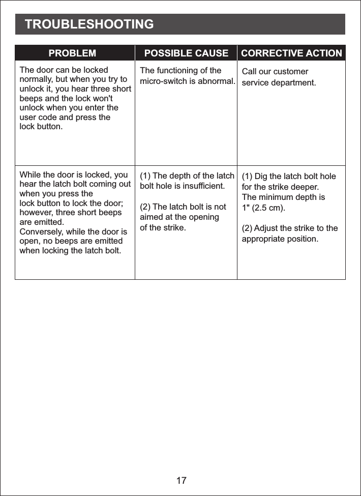
Tong Lung Metal Industry Co.,Ltd. TOUCHPAD ELECTRONIC DEADBOLT LOCK Manual

Manual

1234567890USER MANUALTEMPLATE45 40 351-3/4"  1-9/16"  1-3/8" Fit here on door edgeFOR BACKSET 70mm (2-3/4”)FOR BACKSET 60mm (2-3/8”)Mark Ø1" (25.4mm) hole atcenter of door edge.Ø54mm (2-1/8")Attention : Please do not use  the "electronic" screwdriver for installation.Product : Purchase Date : Limited Warranty Statements1. WarrantyThe manufacturer warrants the Product to be freefrom defects in material and workmanship for a period of 12 monthsfrom the original date of purchase.If you discover a defect in the Product covered by this warranty, we will repair orreplace the item at our option using new or refurbished components.  2. ExclusionsThis warranty covers defects in manufacturing discovered while using theProducts as recommended by The manufacturer rather than occurred by the actof God, and damages caused by misuse, abuse, and unauthorized modification.   3. Limited of LiabilityThe manufacturer will not be held liable for incidental or consequential losses ordamages to any act of God. 4. ReminderService requirement shall subject to the presentation of this warranty cardand defective parts to the manufacturer.The warranty card will not be reissued if lost.  TOUCHPADELECTRONIC DEADBOLT LOCK
1PACKAGE CONTENTSABCDEFGHILKJPART DESCRIPTION QUANTITYABCDEFGHIJKLKeyCylinderDeadbolt  pad AssemblyTouchDeadbolt LatchStrike PlateMounting PlateReceiver AssemblyBattery CoverDrive-in Sleeve211111111352Machine ScrewsWood ScrewsDeadbolt Chassis Screws
2Machine ScrewsQty. 3Wood ScrewsQty. 5Deadbolt  Chassis Screws    Qty. 2J KLHARDWARE SCREWS CONTENTS LATCH BACKSET ADJUSTMENTRemarks: Please notice the   the latch box between two different backsets.slight differences in180°2 3/4" (70 mm)2 3/8" (60 mm)70 mm60 mm
3122.11. Backset DeterminationBackset is a distance from door edge tocentre of hole on door face.Adjustable latch fits both backset of2 3/8" (60 mm) and 2 3/4" (70 mm). 2. Change Latch FaceDetermine which latch mounting method willbe used and make necessary adjustments.No adjustment required for square latchface plate. a. Use a flat screwdriver to separate the    face plate.b. Snap selected latch face plate onto back    plate. Drive-in LatchDrive-in InstallationRemove original latch faceplate. Align the   (I) as illustrated andsnap into the latch case.drive-in sleeveabDDIASSEMBLY INSTRUCTIONS
43452 3/4" (70 mm)3. Latch Backset AdjustmentDetermine if the latch (D) needs to be adjustedto the 2 3/4" (70 mm) backset.To adjust, rotate the latch until it stops.Reverse the direction to return to the2 3/8" (60 mm) backset.4. Mark the Door with TemplateSelect the height and backset as desired onthe door face; use the TEMPLATE as anindication to mark the centre of the circle onthe door face and the centre of the dooredge.5. Drill HolesUsing the marks as a guide to drill a holeØ2 1/8" (54 mm) through the door face forthe lockset, then a hole of Ø1" (25.4 mm)for latch.DASSEMBLY INSTRUCTIONS
56786. Mark the Outline of Latch FaceplateInsert the latch (D) and ensure it is parallel tothe door face.Mark the outline of the faceplate, thentake out the latch (D).  7. Chisel Space for Latch FaceplateChisel 5/32" (4 mm) deep along the outlineto allow the faceplate to be aligned withthe door edge.Note: It is not necessary to chisel the door          edge for the faceplate installation if          you use the drive-in latch.  8. Install LatchInsert the latch (D) into the door. (Make sure the cross is on the bottom of the latch.) Use 2 wood screws (K) to secure latch.Please do not fully tighten the screws untillock is completely installed.Hardware UsedKWood screws               x2DDKASSEMBLY INSTRUCTIONSYou need to staythis way up wheninserting the latch.Make sure the cross in thelatch is on the bottom.
68.1910Install Drive-in LatchDrive the latch (D) into the hole on edge ofdoor.9. Mark the Outline of StrikeTo identify the centre of strike: close thedoor to lay the latchbolt against the doorframe. Mark the centre line on the doorframeexactly opposite the latch hole in the dooredge.10.1 Drill Hole on Door FrameMeasure one half of door thickness from doorstop and vertically mark centre line of strike.Drill 1" (25.4 mm) hole, 1" (25.4 mm)deep at intersection of horizontal and verticalline of strike.10.2 Chisel Space for StrikeChisel 5/64" (2 mm) deep along the strikeoutline to allow the strike to be aligned withthe doorframe.DDASSEMBLY INSTRUCTIONS
711121311. Install Strike on Door Frame Install the strike plate (E) into your door frameand tighten with wood screws (K).12. Install Touchpad AssemblyMake sure the latch bolt is retracted.13. Install   AssemblyTouchpadtouchpadInstall cylinder (B) into the deadbolt assembly (C) with tailpiece in horizontalposition inserted through hub of the latch.EKDASSEMBLY INSTRUCTIONSBHardware UsedKWood screws               x2horizontal positionCC
Left-handed Right-handedHardware Used8LDeadbolt chassis screws                           x2151614. Install   Assembly Pass the IC wire under the latch (D) to theinterior side of the door, and insert thetailpiece through the cross-shaped crankof the latchTouchpad.15. Install Inside Mounting PlatePass the IC wire through the wire hole of themounting plate (F). Fix the mounting plate (F)with screws (L). If outside lock assembly islopsided, please loosen the screws to adjustits position and tighten the screws again.16. Identify Door HandingFace the door from the outside. Thedoor is left-handed if the hinges areon the left side of the door, whereasthe door is right-handed if the hingesare on the right side of the door.LFASSEMBLY INSTRUCTIONSHinge Hingehorizontal position14DCBIC wire
Hardware Used9171819For right-handeddoorFor left-handeddoor17. Adjust Thumb Turn PieceRotate the thumb turn piece to the LEFT at45 degrees for right-handed doors.Rotate the thumb turn piece to the RIGHT at45 degrees for left-handed doors.18. Install Receiver ModuleRemove the battery cover (H)(push it up first then pull it out).19. Install Receiver ModuleConnect the IC wire into the back of thereceiver module. Ensure that the deadbolttailpiece is engaged with turn piece, thenattach receiver module (G) to the door withscrew (J). Use the optional wood screw (K)to secure the receiver module to wood doorsonly.JMachine screws                     x3GH GGFKJASSEMBLY INSTRUCTIONSKWood screw               x1This screw is optional. It may not be necessary touse this screw.
2020. Insert Batteries Insert 4 (AA) 1.5 V alkaline batteries andslide the battery cover (H) back onto thereceiver module (G).Remarks: (1) Alkaline batteries are recommended in     order to stabilize the power supply. If you     don't use alkaline, battery performance     will be reduced greatly.(2) All settings will be retained in the memory     even if the batteries are completed dead.10G HASSEMBLY INSTRUCTIONS
123456789011 Programming Button      Programming button is for setting function.         . Cylinder        To lock/unlock the lockset  from outside. Washer        Prevents water from permeating into lockset. Battery Lid       Slide the lid to change the batteries. Battery Holder     Four AA (1.5 V) alkaline batteries. R Button (Reset)       Restore default settings. Turn-piece       To lock/unlock the lockset from inside.Lock BtuttonLock Button is for lock and unlock functionby key OPERATIONAL INTERFACE
12Keep the door open while programming to avoid being locked out    accidentally. The lock contains one factory-preset user code but can be    programmed to store up to a total of six additional unique user codes.˙Codes can be added and deleted at any time. For first-time programming,use factory default programming code. It’s recommended to change the    default programming code and default user code right after you install    the lock. ˙    Every programming step should be done within 6 seconds.OPERATING INSTRUCTIONSOperation Indicator Sounds and LightsSounds Lights MeaningSuccessful OperationSuccessful ProgrammingOperation ErrorCode Input Error;System Shuts DownLow Battery PowerDefault Setting RestoredIn Programming Mode1 Beep2 Long Beeps3 Beeps5 Beeps10 Rapid BeepsLock button flashes slowly3 Long Beeps
3. Add New User CodeNote:           4–10 digits in length. Up to 30 sets of user codes can be saved. User codes should be13OPERATING INSTRUCTIONS2. Change Programming Code4. Delete an Existing User Code5. Delete All User Codes at OnceNote:          user codes are deleted.          The lock can only be operated by key during that time. Auto-locking and keypad locking functions will be invalid whenDefault programming code (PC): 0000Default user code (UC): 1234Your new programming code (PC) ____________Your new user code (UC) ___________________The same programming code and user code cannot be accepted. The lock will cease operation if unauthorized codes are enteredover 5 times. The system will unfreeze after 45 seconds. DO THIS FIRST1. Door Handling Identification ProcessThe lock needs to learn if your door is a right- or left-handed .!0Enter PC4Enter PC EnterNew PC1Enter PC EnterNew UC2Enter PCEnterthe UC youwant todelete3Enter PC
14OPERATING INSTRUCTIONS8. Enable/Disable All User CodesNote:           user codes are disabled. The lock can only be operated by key          during the time. Repeat the steps to enable the user codes again.Auto-locking and keypad locking functions will be invalid when9. Create a One-Time User Code 4–10 Digits LongNote: The one-time user code will automatically cancel after it is used          one time.6. Toggle Auto-Lock On/OffNote:            following instructions #7.           Repeat the steps in #6 to cancel the auto-locking function.The preset delay-time is 30 seconds, you can change the time by7. Set Auto-Lock Time DelayNote: 10–99 seconds delay-time available.5Enter PC6Enter PCEnterSeconds(10~99)7Enter PC8Enter PCEnterOne TimeCode
OPERATING INSTRUCTIONS1510. Restore Default SettingsPress RNote: Press the button for more than 5 seconds;           the programming is reset back to the original          factory codes once you hear 3 long beeps.          After restoring default settings, you must run          the door handing identifying process (#1)          again before programming any other          functions. RResetbuttonWARRANTYCARE AND MAINTENANCEDo not use any chemical liquid or lubricating oil with additives to clean thelock body. It will damage the surface or even mainboard.The manufacturer warrants the product to be free from defects in materialand workmanship for a period of 12 months from the original date ofpurchase. If you discover a defect in the product covered by this warranty,we will repair or replace the item at our option using new or refurbishedcomponents.EXCLUSIONSThis warranty covers defects in manufacturing discovered while using theproducts as recommended by the manufacturer rather than occurred bythe act of God, and damages caused by misuse, abuse, and unauthorizedmodification.LIMITED LIABILITYThe manufacturer will not be held liable for incidental or consequentiallosses or damages from any act of God.R
16After installing the locksetand batteries, the doorcan’t be locked and threeshort beeps are emittedwhen you press thelock button.The door-handingidentification processisn’t yet complete.Refer to step1, page13.You’ve installed thelockset and batteries, butyou still get no responsewhen you press anybutton.Batteries were installedincorrectly and cableconnect incorrectly.Check to see if the batterypolarities have beenreversed or if the battery isdead. If so, re-install orchange the battery. If not,please check to see if thecable is properlyconnected.When you are in thedoor-handing identifyingprocess, you hear threetimes, and three shortbeeps.Wrong door-handing orchange of thedoor-handing in thememory.Press the R button torestore the system tofactory default setting andre-execute door-handingidentifying process (step 1, page 13)Although you succeededin the first execution ofthe door-handingidentifying process, thelatch still doesn’t work.(i.e. You can feel the motorattempting to run.)Low battery. Replace with new alkalinebatteries.PROBLEM POSSIBLE CAUSE CORRECTIVE ACTIONTROUBLESHOOTING
17The door can be lockednormally, but when you try tounlock it, you hear three shortbeeps and the lock won'tunlock when you enter theuser code and press thelock button.The functioning of themicro-switch is abnormal.Call our customerservice department While the door is locked, youhear the latch bolt coming outwhen you press thelock button to lock the door; however, three short beepsare emitted.Conversely, while the door isopen, no beeps are emittedwhen locking the latch bolt.(1) The depth of the latchbolt hole is insufficient.(2) The latch bolt is notaimed at the openingof the strike.(1) Dig the latch bolt holefor the strike (2) Adjust the strike to theappropriate position.deeper.The minimum depth is1" (2.5 cm). PROBLEM POSSIBLE CAUSE CORRECTIVE ACTIONTROUBLESHOOTING.
正面148x105mm ( )背面148x105mm ( )• • Añadir la cerradura a su pasarela Z-Wave→→Si escucha 2 pitidos la programación de su cerradura fue exitosa. Si escucha    5 pitidos debe iniciar el proceso nuevamente ya que la programación no se completó    adecuadamente.Eliminar la cerradura de su pasarela Z-Wave→Presione eliminar dispositivo en su aplicación, luego siga estos    pasos en su cerradura.→Si escucha 5 pitidos debe iniciar el proceso nuevamente ya que    la eliminación no fue exitosa.Presione añadir dispositivo en su aplicación, luego siga estos pasos en su cerradura. then back to lock.Tap add device on your app, then back to lock.Añadir/Eliminar cerradura12345678909Ingresar código de programación9Ingresar código de programaciónCumplimiento de normasEste producto cumple con los estándares establecidos por los siguientes entes reguladores:Federal Communications   (FCC)Industry CanadaFCCEste dispositivo cumple con la sección 15 de las reglas de la FCC. La operación está sujeta a las siguientes dos condiciones:(1)Este dispositivo no ha de causar interferencias dañinas, y (2) este dispositivo debe aceptar cualquier interferencia recibida, incluyendo unainterferencia que podría causar una operación no deseada.Este equipo se ha sometido a pruebas y cumplió con los estándares de un dispositivo digital Clase B, en referencia a la sección 15 de las reglasde la FCC.Estos estándares están diseñados de tal forma que provean una protección razonable en contra de interferencia dañina en una instalación residencial. Este equipo genera, utiliza y podría irradiar energía de frecuencia de radio y, de no instalarse y utilizarse según las instrucciones, podría causarinterferencia dañina a sus comunicaciones de radio.Sin embargo, no hay garantía de que la interferencia no ocurrirá en una instalación en particular.Si este equipo llegara a causar interferencia dañina a su recepción de radio o televisión, lo cual se podría   al encender o apagar todo el, se aconseja que corrija la interferencia tomando una o más de las siguientes medidas:Traslade a un Nuevo lugar su antena.Aumente la separación entre su equipo y el receptor.Conecte el equipo a un enchufe con un circuito distinto al cual está conectado actualmente.Consulte a su vendedor o a un técnico con experiencia de radio/televisión para ayuda adicional.ImportanteCambios o modificaciones hechas al equipo sin autorización escrita por el manufacturero podría invalidar la autoridad del usuario a operarlo.• • determinarequipo• • • • Commission英文版 正面148x210mm-  ( ) -西文版 背面148x210mm  ( )REGULATORY COMPLIANCEThis product complies with standards established by the following regulatory bodies:• Federal Communications Commission (FCC)• Industry CanadaFCCThis device complies with Part 15 of the FCC Rules. Operation is subject to the following two conditions:( 1 ) this device may not cause harmful interference, and ( 2 ) this device must accept any interference received, including interference       that may cause undesired operation.This equipment has been tested and found to comply with the limits for a Class B digital device, pursuant to Part 15 of the FCC Rules.These limits are designed to provide reasonable protection against harmful interference in a residential installation.This equipment generates, uses, and can radiate radio frequency energy and, if not installed and used in accordancewith the instructions, may cause harmful interference to radio communications.However, there is no guarantee that interference will not occur in a particular installation.If this equipment does cause harmful interference to radio or television reception, which can be determined by turning the equipment off and on,the user is encouraged to try to correct the interference by one or more of the following measures:• Reorient or relocate the receiving antenna.• Increase the separation between the equipment and receiver.• Connect the equipment into an outlet on a circuit different from that to which the receiver is connected.• Consult the dealer or an experienced radio/TV technician for help.IMPORTANT ! Changes or modifications not expressly approved by the manufacturer could void the user' authority to operate the equipment.• Adding lock to your Z-Wave gatewayIf you hear 2 beeps from your lock the programming was successful. If you hear 5    beeps from your lock you must start over again (the programming failed).• Removing lock from your Z-Wave gatewayIf you hear 5 beeps from your lock you must start over again    (the programming failed).→→→Tap add device on your app, then back to lock.→Tab add device on your app, then back to lock. then back to lock.Tap add device on your app, then back to lock.Adding/Removing lock12345678909Enter PC9Enter PCPL2S-Zwave PL2S-Zwave

Navigation menu