Topcon America 050901 GPS Survey Receiver User Manual GR 3 Operator s Manual
Topcon America Corporation GPS Survey Receiver GR 3 Operator s Manual
UserManual.wiki
>
Topcon America
>
050901 User Manual
User manual
Navigation menu
Upload a User Manual
Namespaces
Wiki Guide
HTML
PDF
Info
Views
User Manual
Discussion / Help
Navigation

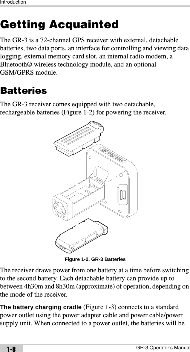
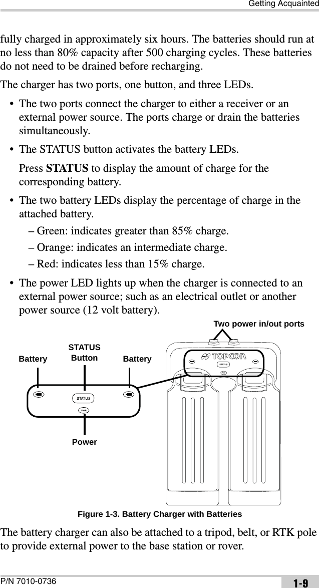
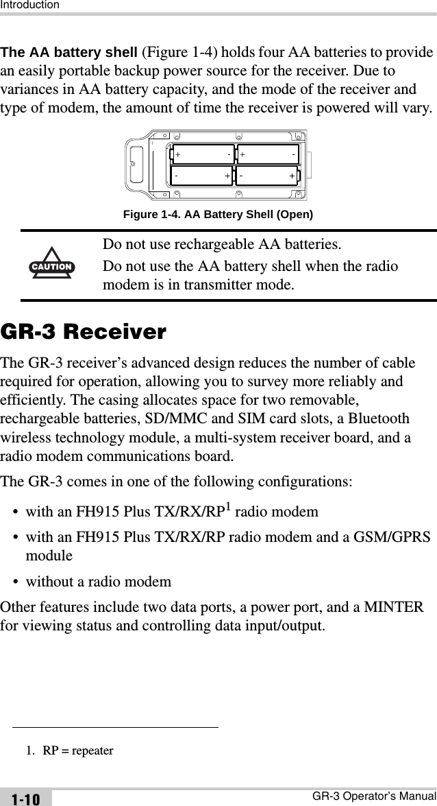
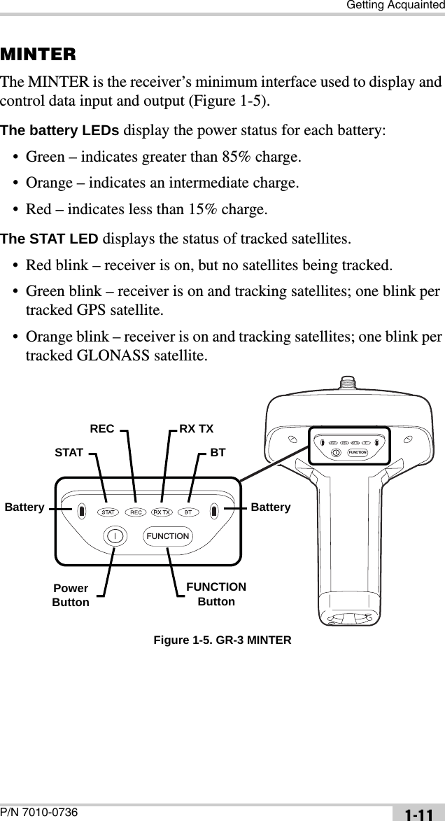
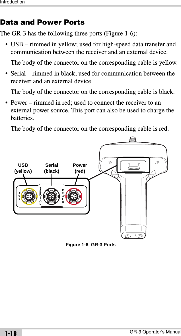
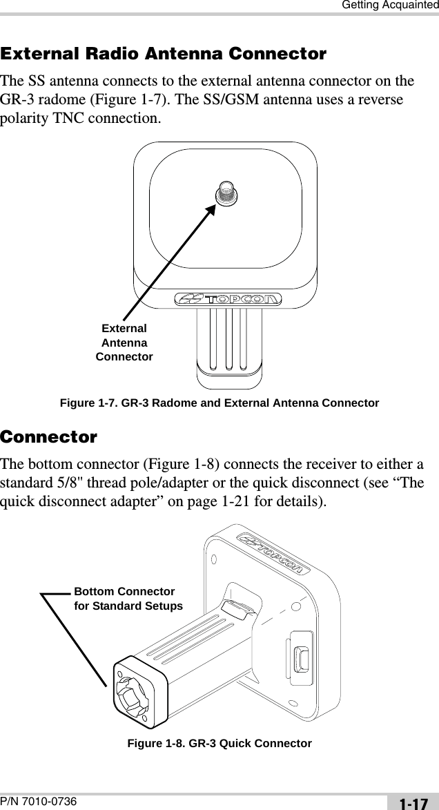
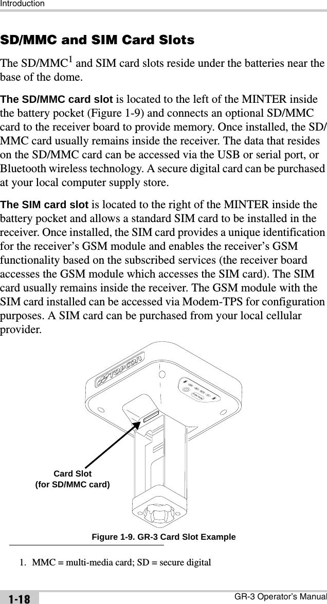
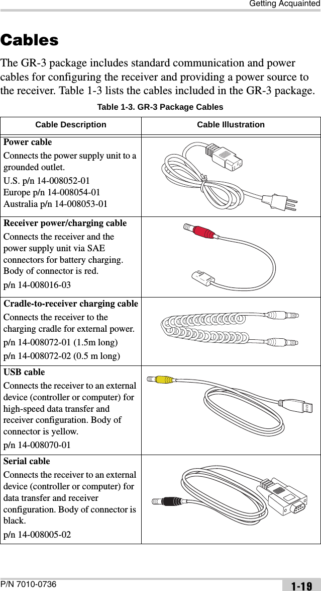
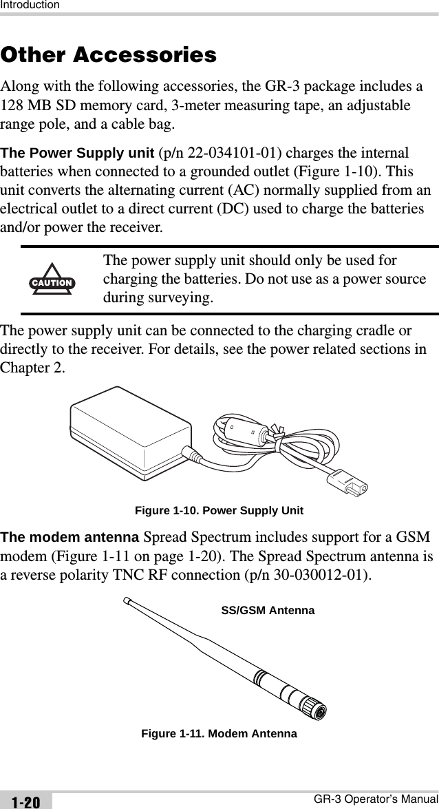

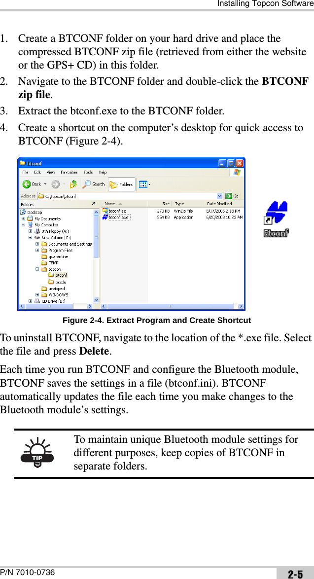
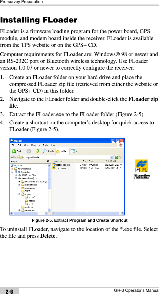
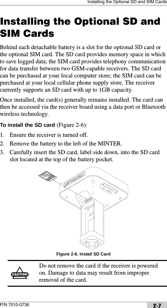
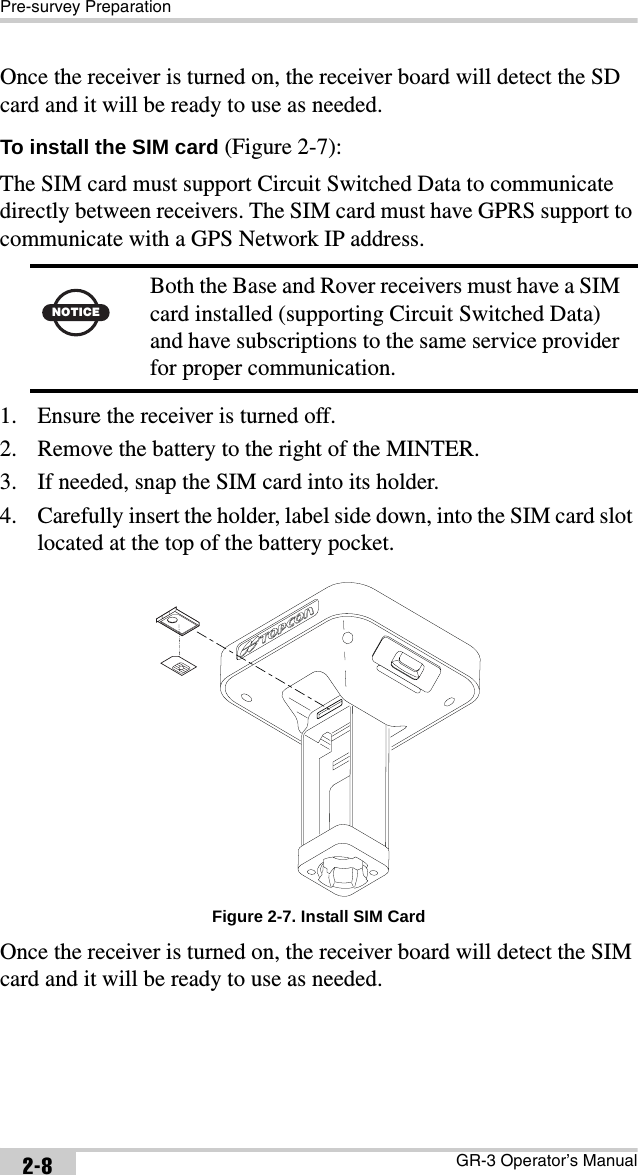
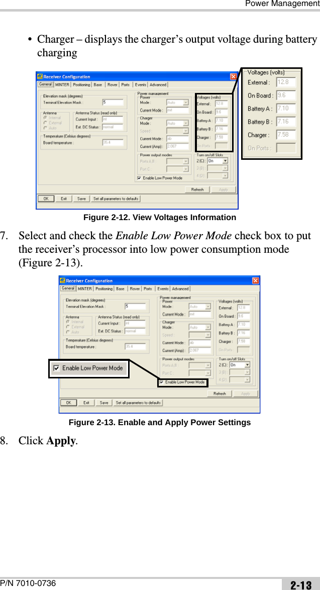
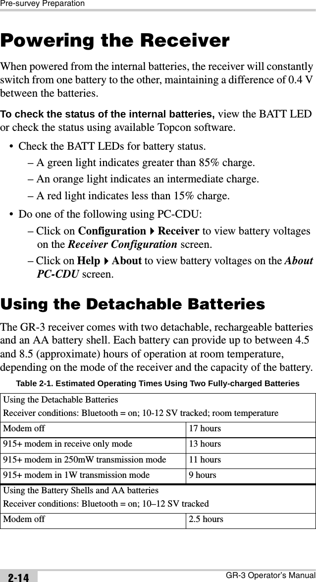
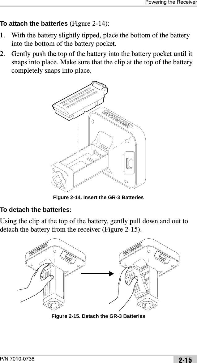
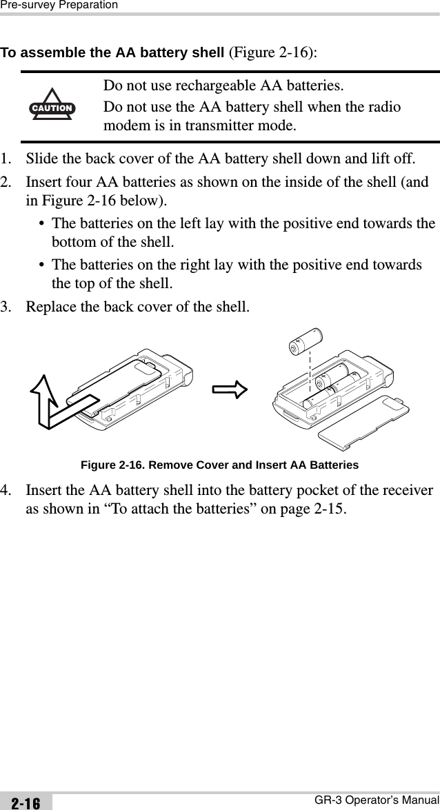
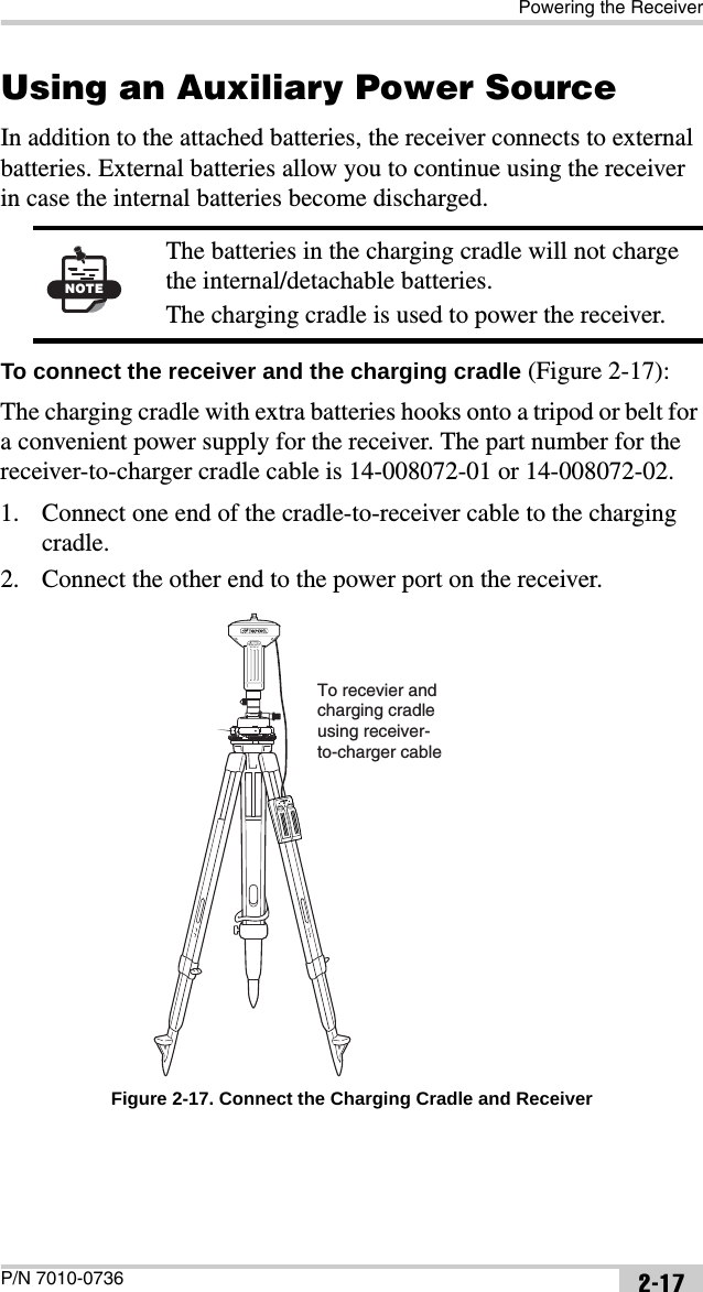
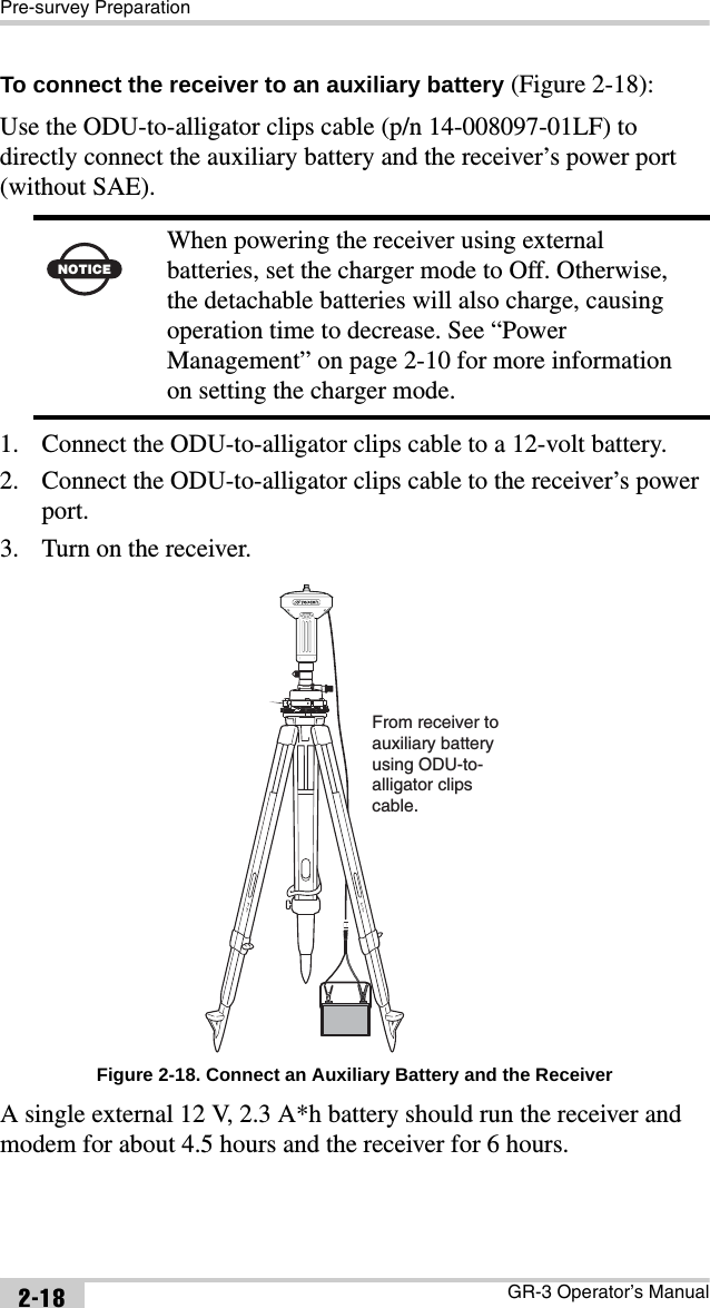


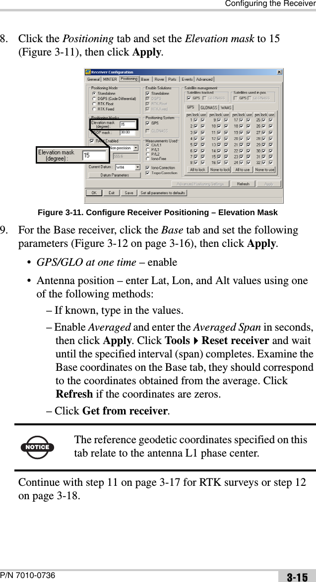
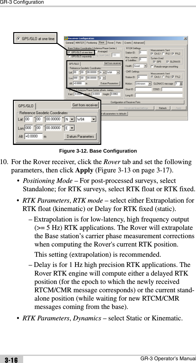
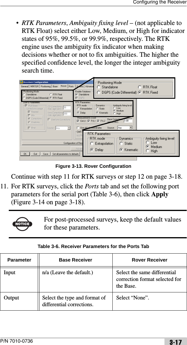
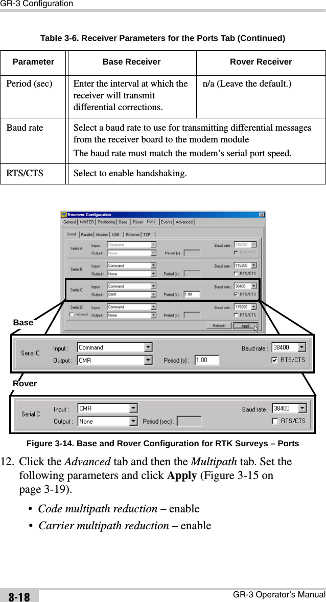
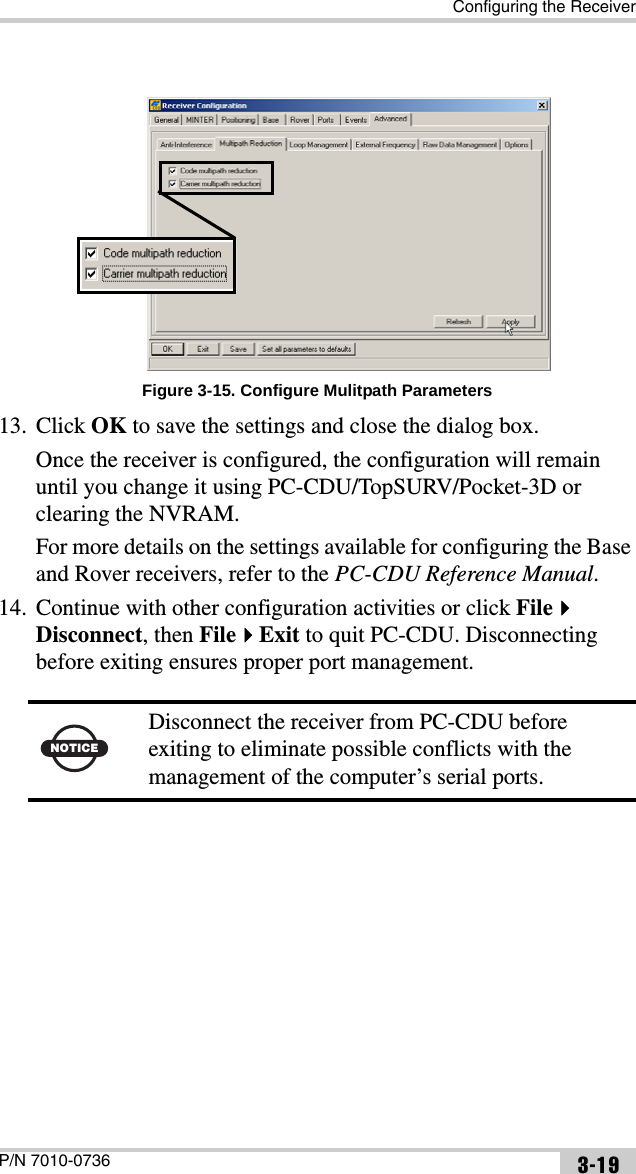
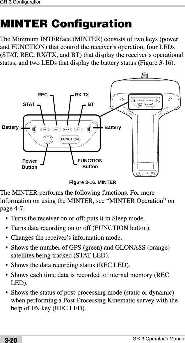
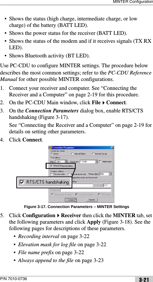
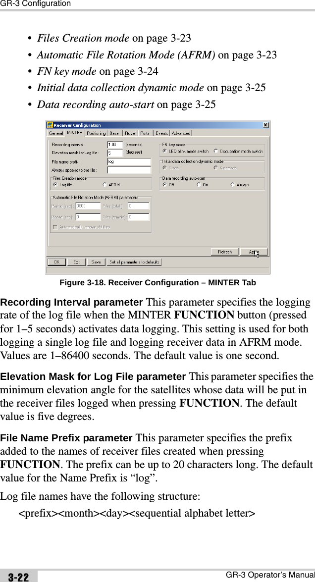
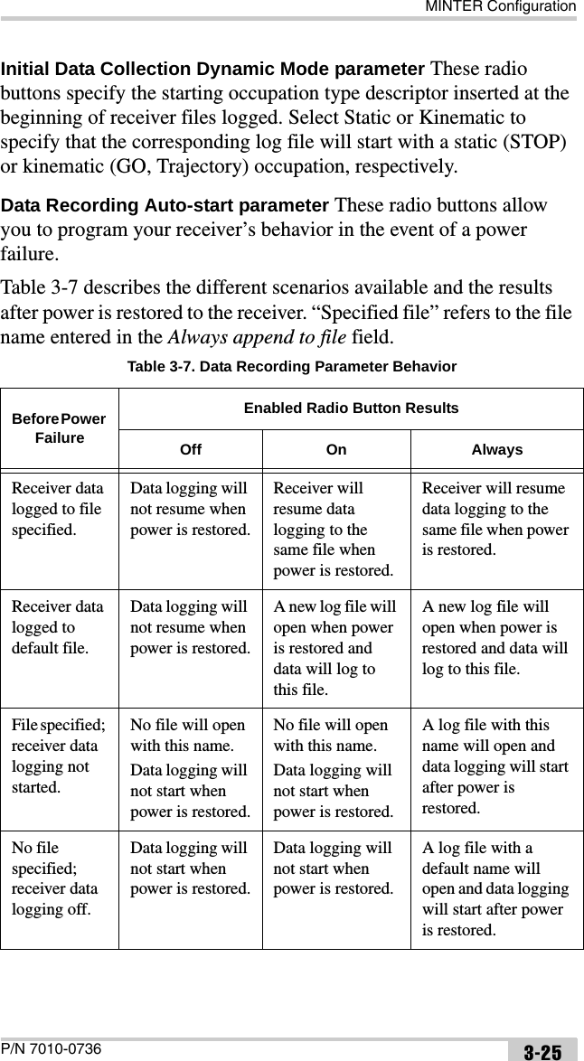
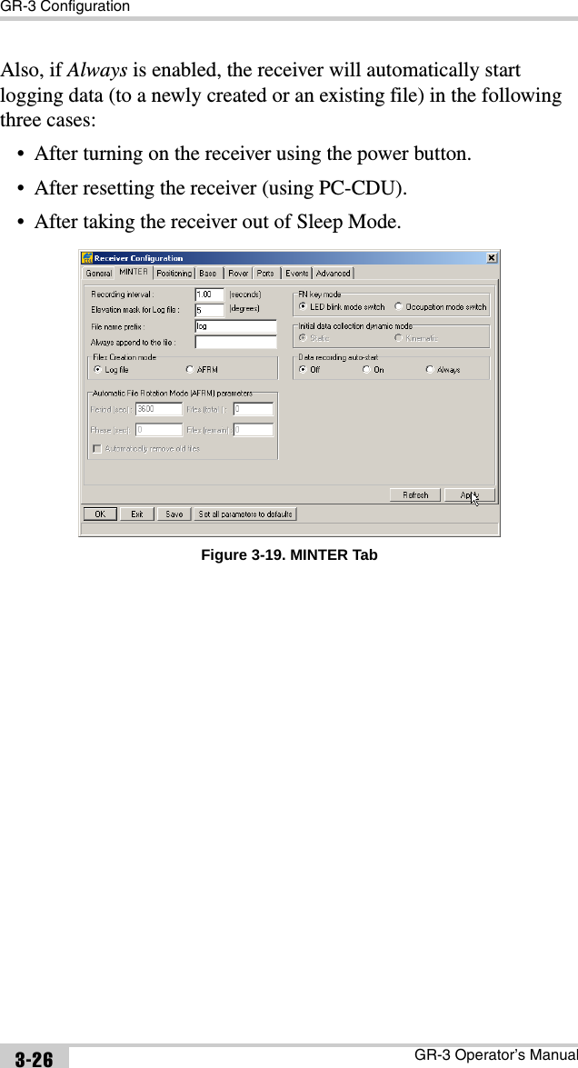
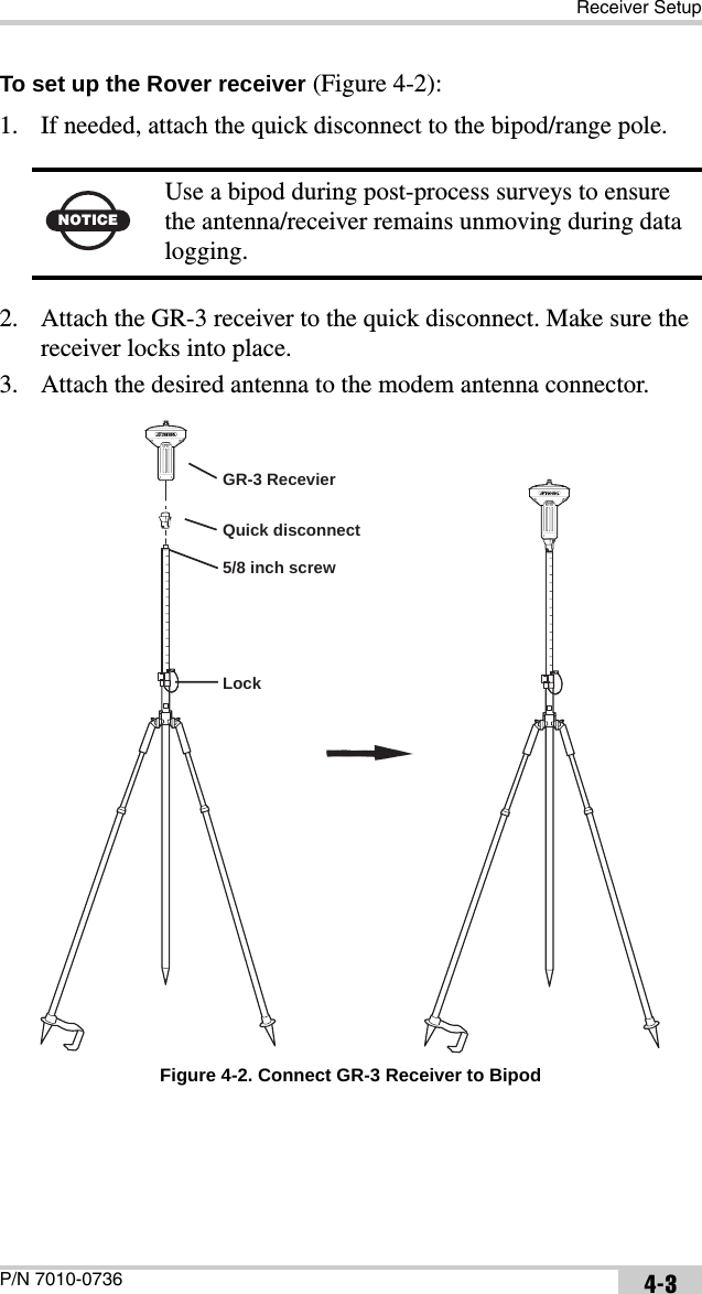
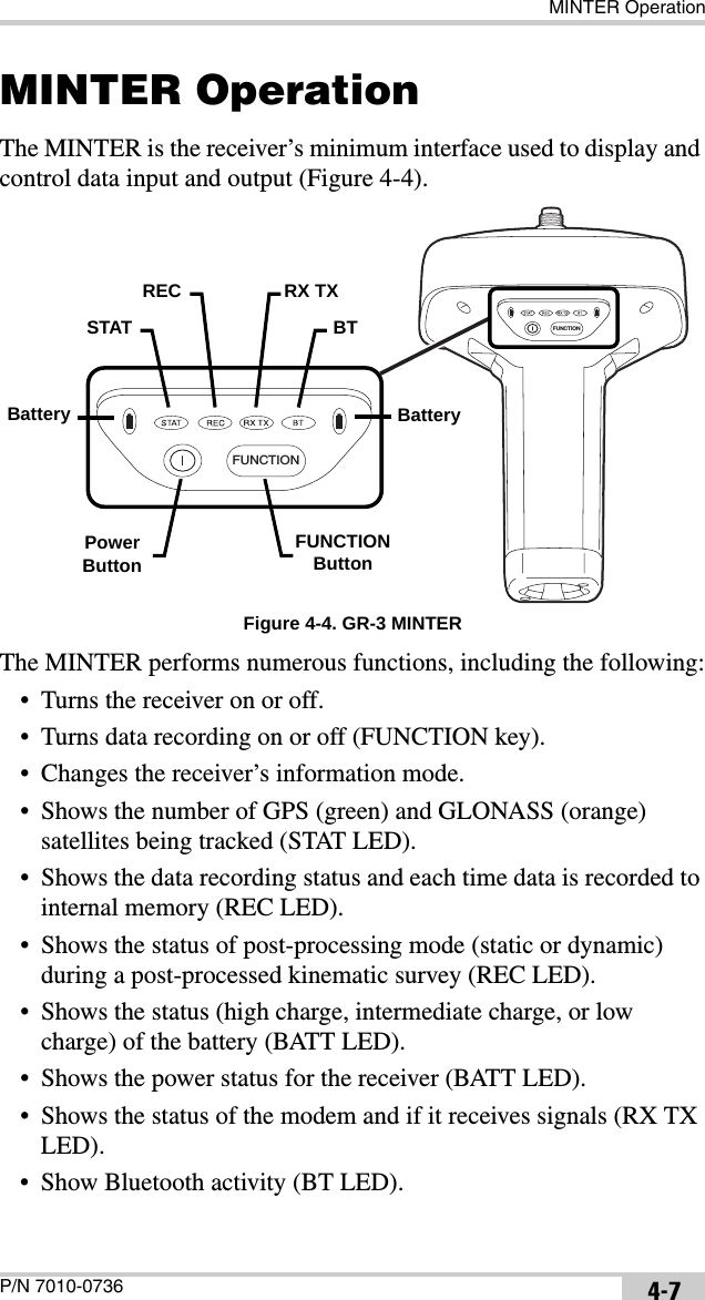
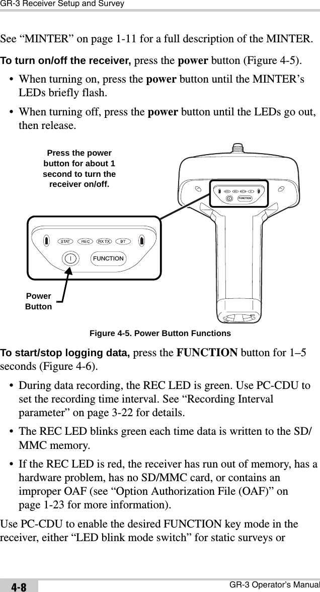
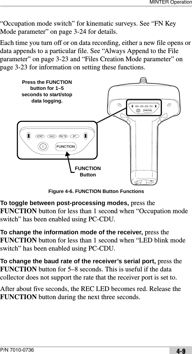
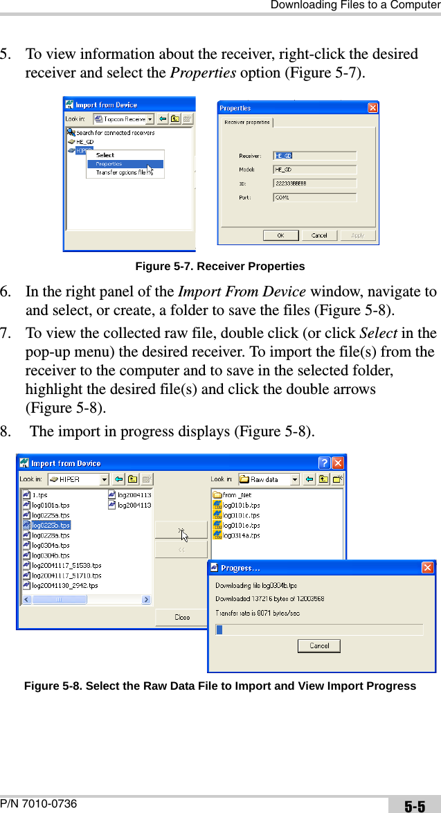
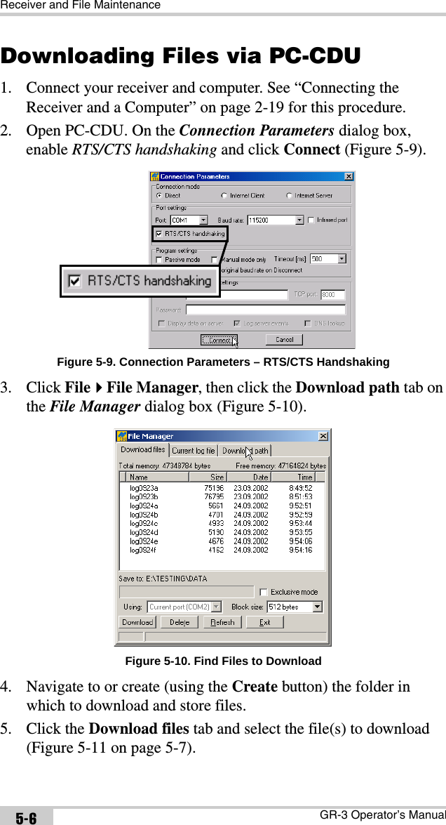
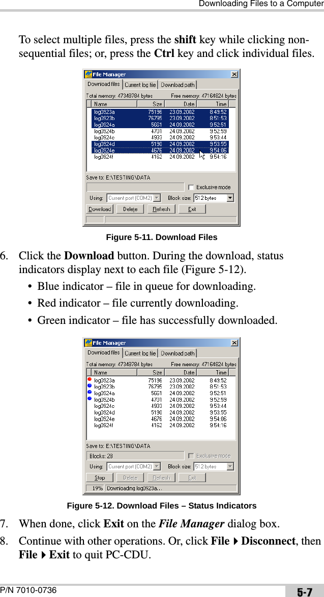
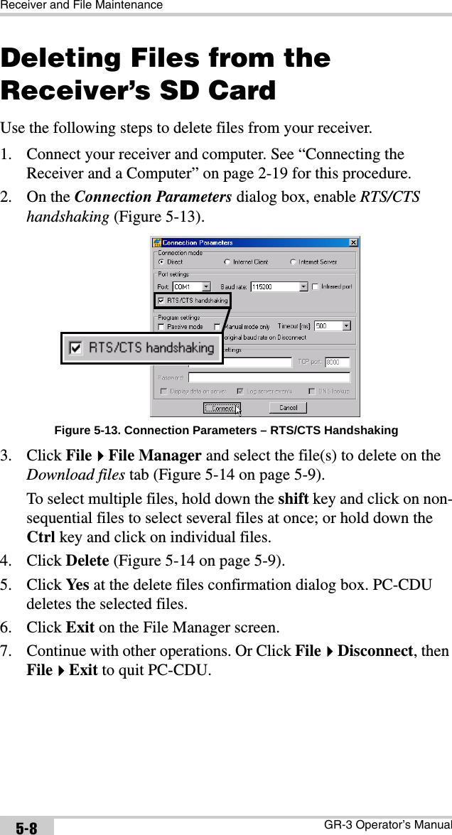
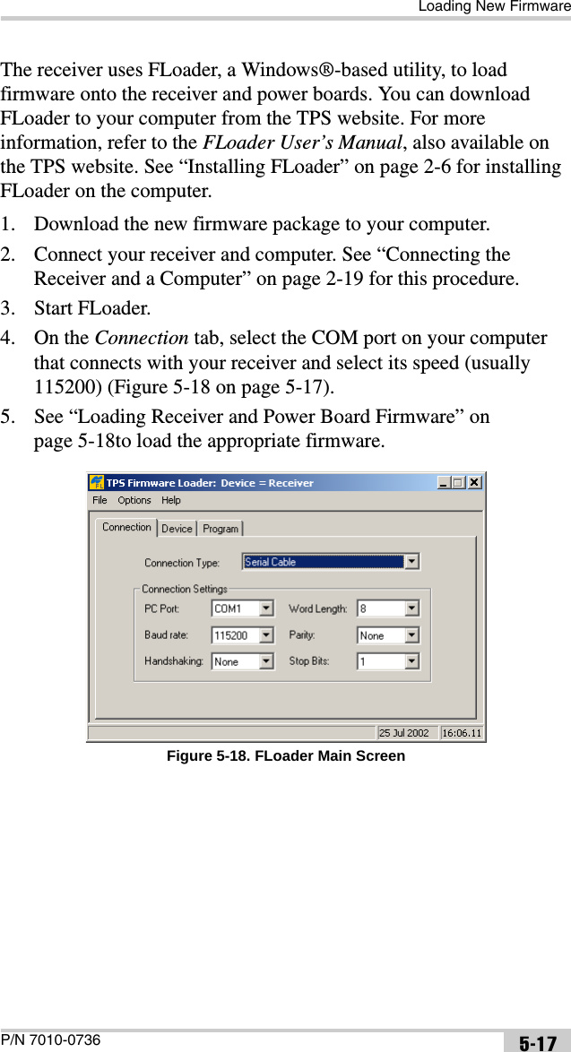
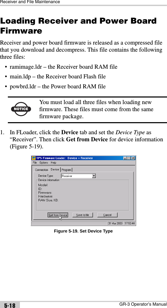
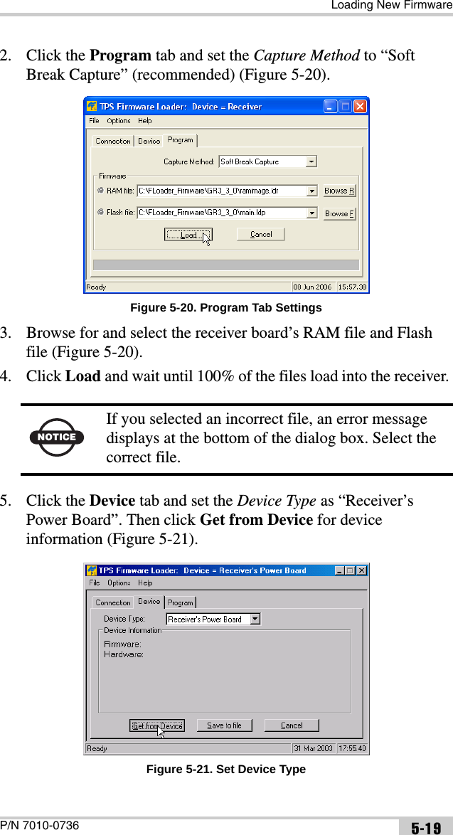
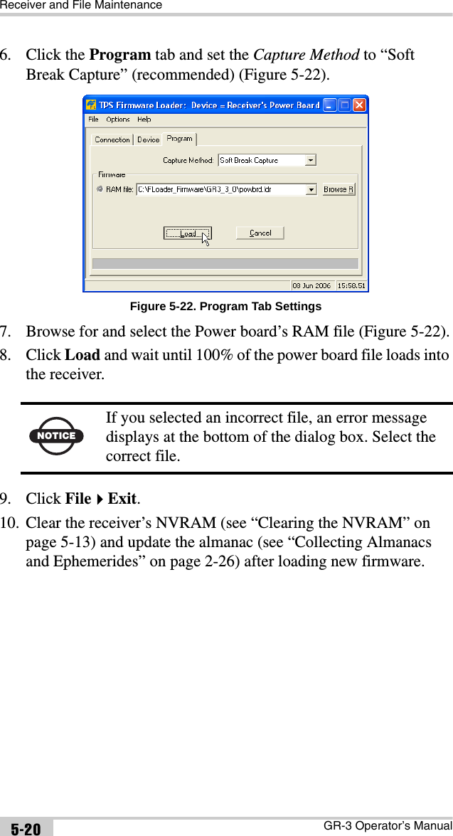
![GR-3 ConfigurationGR-3 Operator’s Manual3-24becomes zero, then file rotation automatically stops. The counter initializes with AFRM.Note that a log file opens immediately after turning AFRM on. This startup file is not considered a file rotation event; the AFRM counter will not decrement.Values are 0 to [231-1]; default value is 0 (zero). Zero means that an unlimited number of log files will be created. • Files (remain) – specifies the number of files left for the receiver to create in AFRM. Values are 0 to [231-1]; default value is zero.• Automatically remove old files – when no free memory is available to log data, automatically removes the earliest log file. If this parameter is enabled, your receiver will erase the file with the earliest file creation time/date. AFRM must be enabled to use this FIFO (First-In, First-Out) feature. The default value is off (disabled).FN Key Mode parameter Use these two radio buttons to program how the receiver will react when pressing the FUNCTION key.• LED blink mode switch – pressing FUNCTION will toggle between the MINTER’s normal/extended information modes and start/stop data recording of Static survey.– FUNCTION pressed for less than 1 second: changes the information mode (Normal or Extended Information Modes).– FUNCTION pressed for 1 to 5 seconds: starts or stops data recording (Static post-processing mode).• Occupation mode switch – pressing FUNCTION (less than one second) will insert into the corresponding log file a message indicating that the survey type has been changed from static to kinematic, or vice versa. If the REC LED blinks green, the current mode is dynamic, if it blinks orange, the current mode is static. For more details, see Table 1-2 on page 1-14 and refer to the PC-CDU Reference Manual.NOTICE The receiver’s memory holds up to 512 files.](https://usermanual.wiki/Topcon-America/050901/User-Guide-686022-Page-90.png)