Topcon America 052001 Beacon receiver User Manual BR 1 Operator s Manual
Topcon America Corporation Beacon receiver BR 1 Operator s Manual
UserManual.wiki
>
Topcon America
>
052001 User Manual
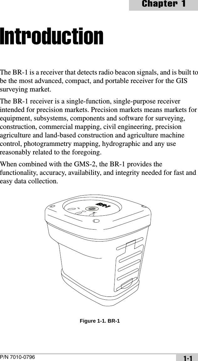
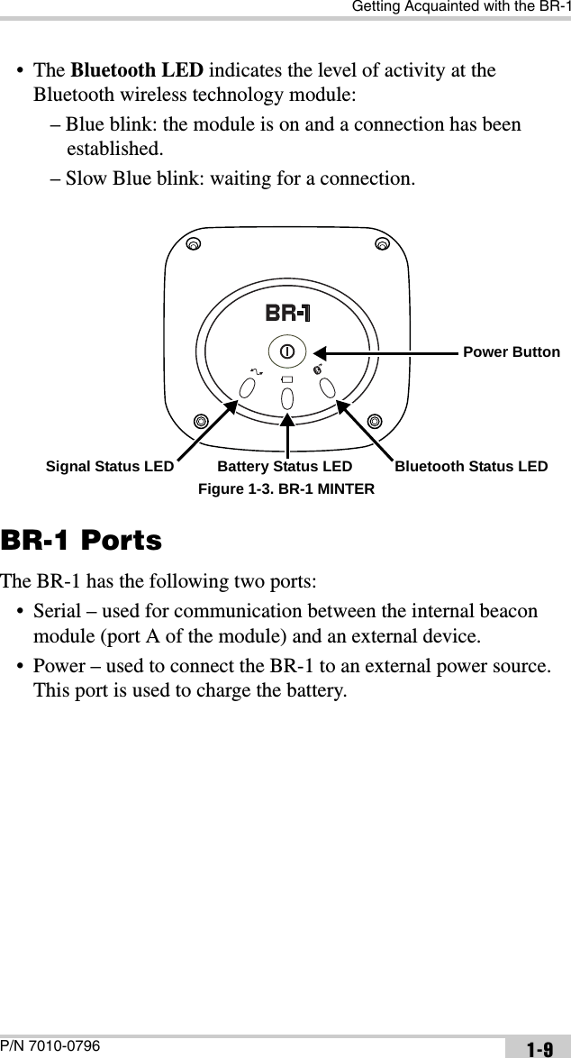
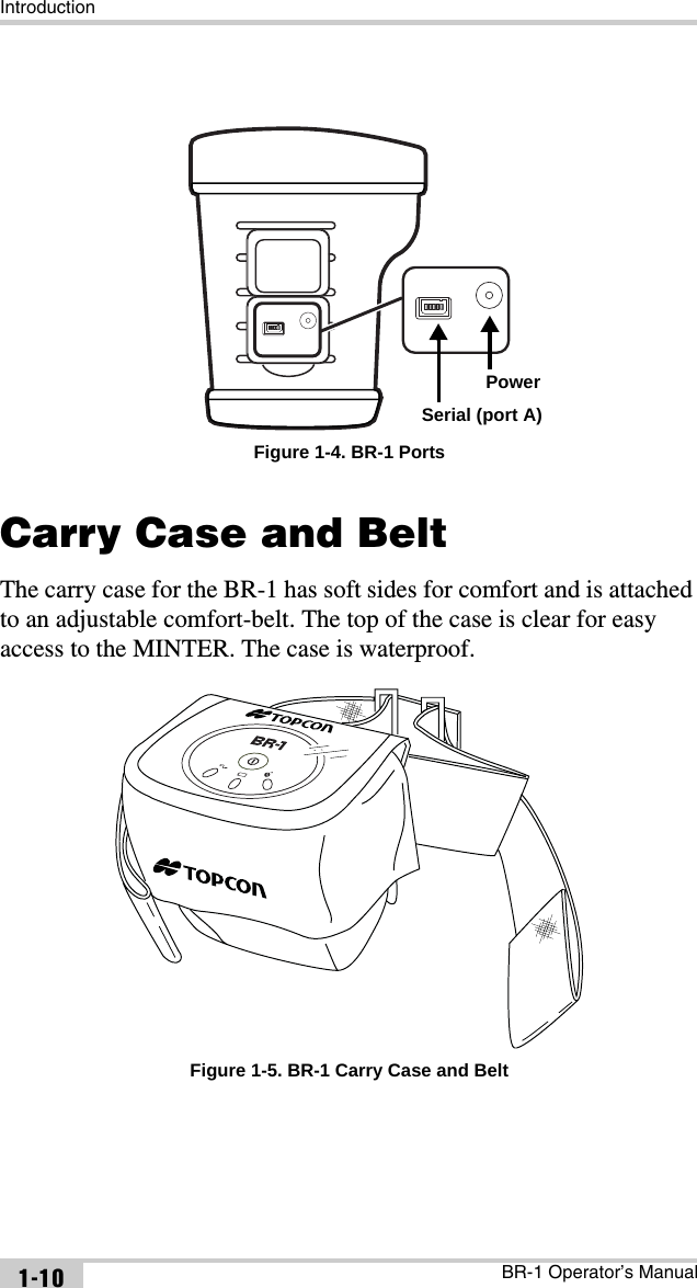
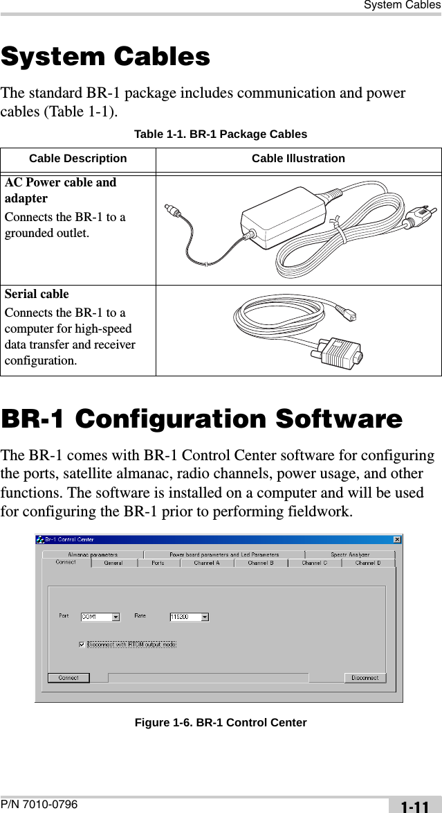
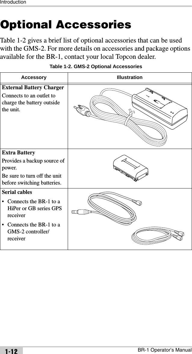
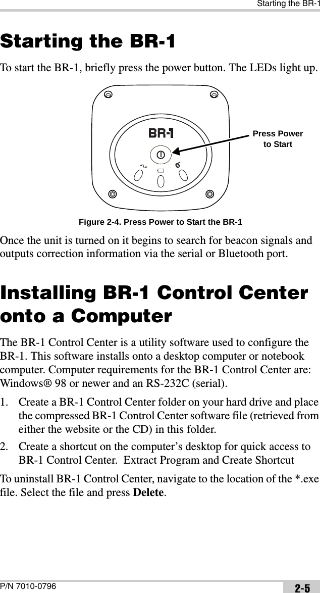
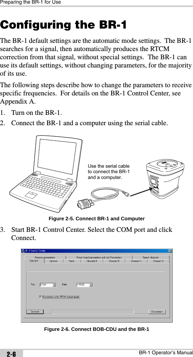
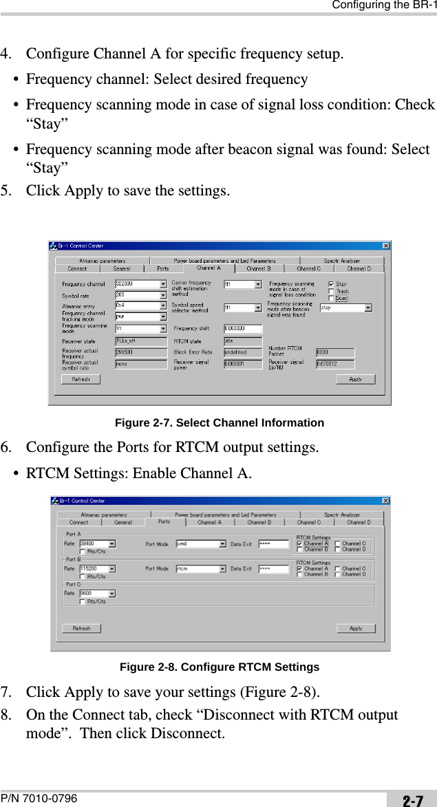
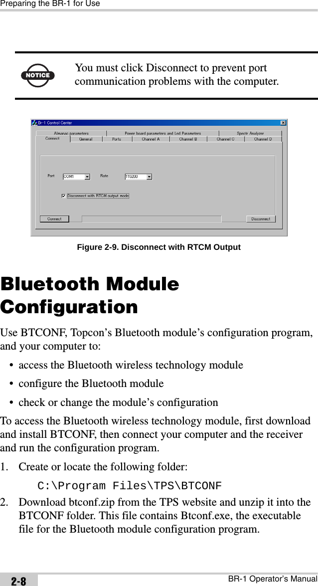
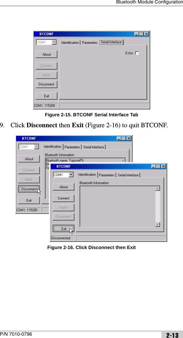
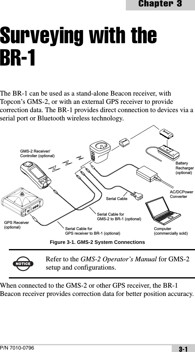
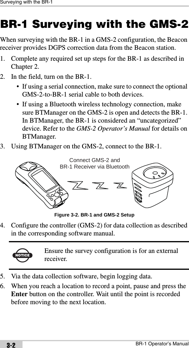
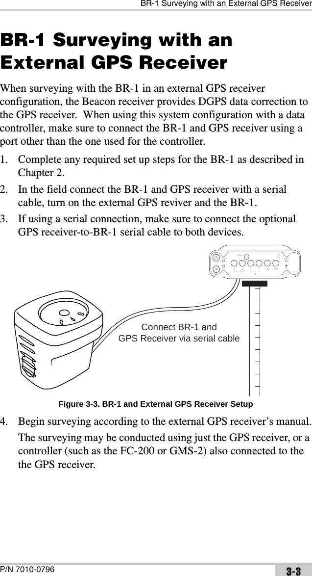
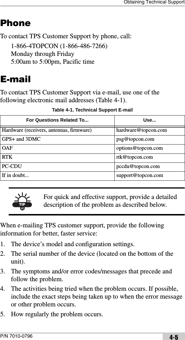
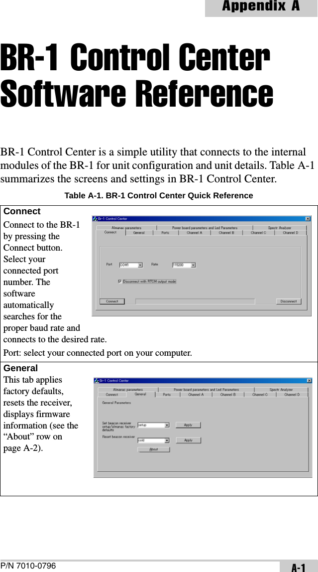
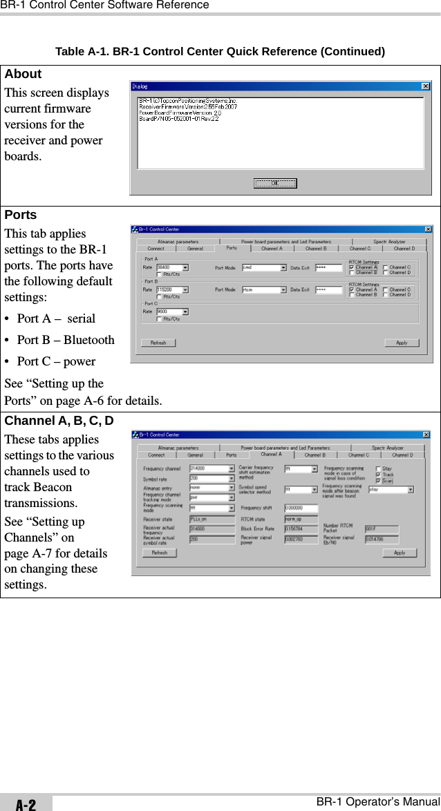
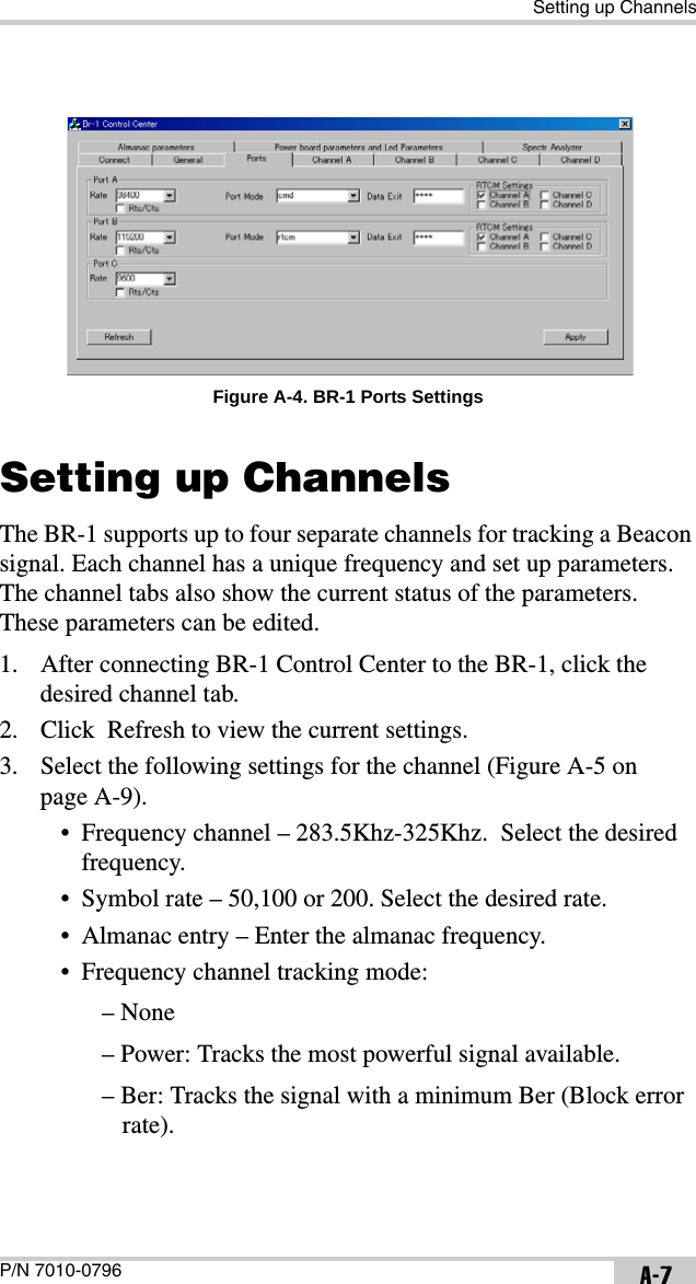
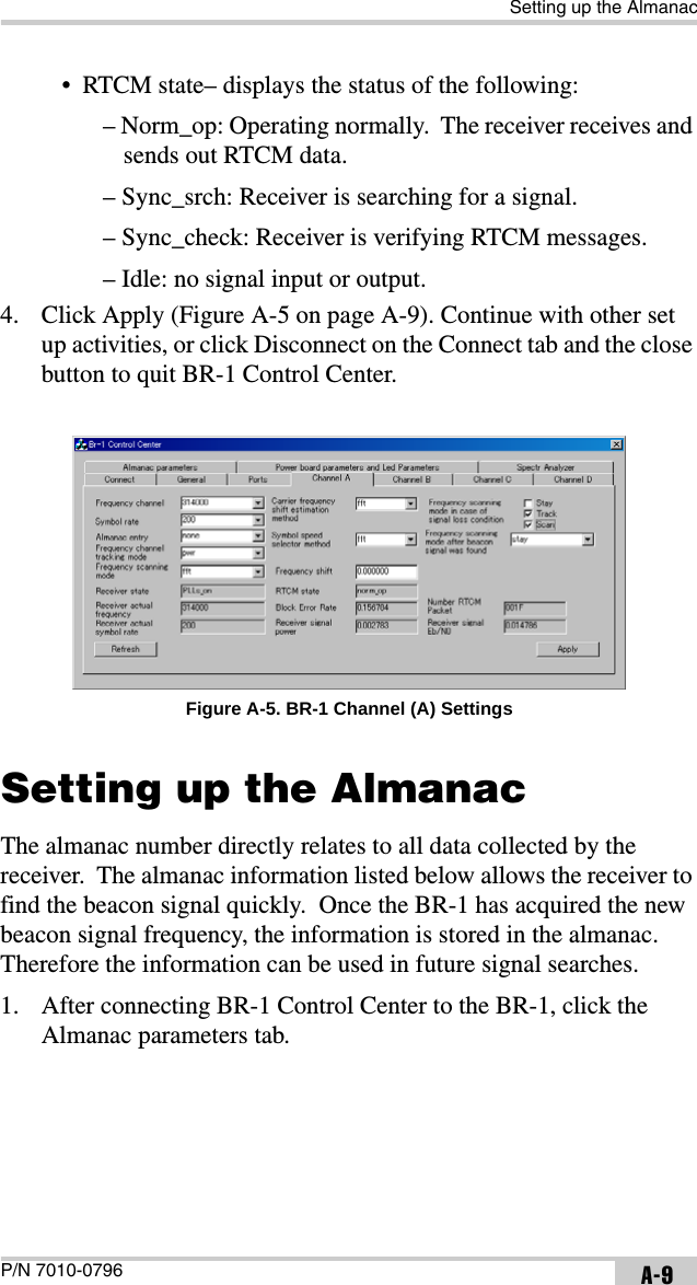
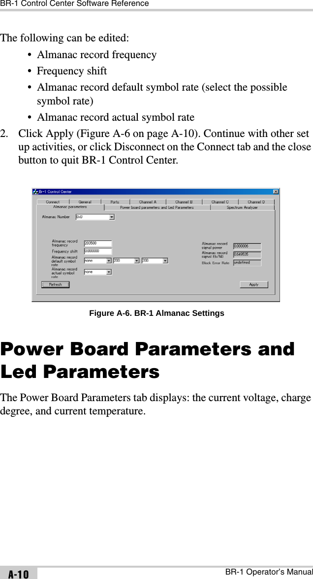
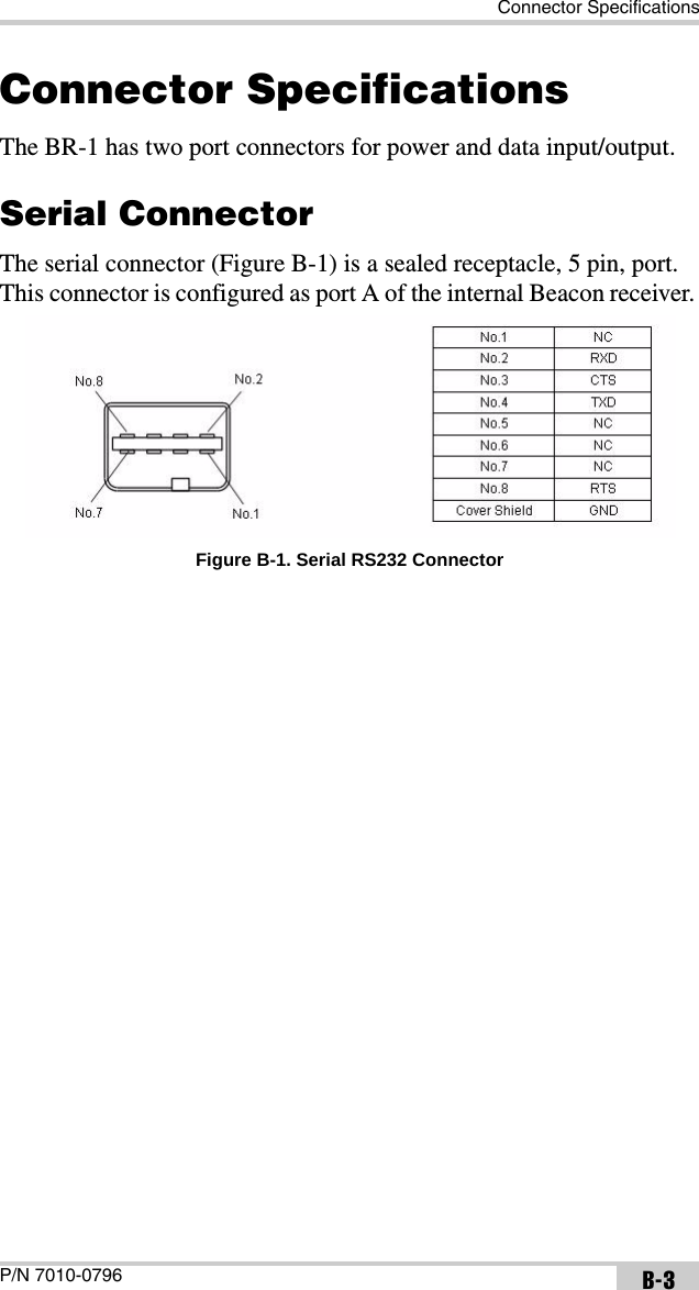
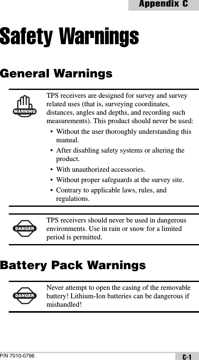
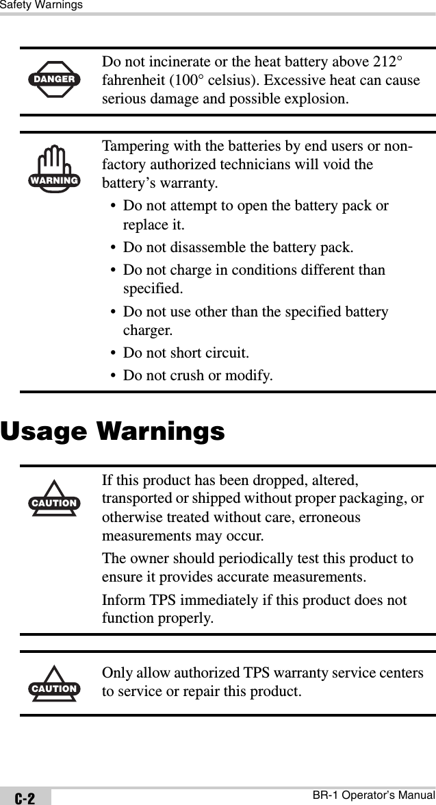
Operators manual
Navigation menu
Upload a User Manual
Namespaces
Wiki Guide
HTML
PDF
Info
Views
User Manual
Discussion / Help
Navigation